Article

Investigating the Performance of a Zinc Oxide Impregnated Polyvinyl Alcohol-Based Low-Cost Cation Exchange Membrane in Microbial Fuel Cells

1
Nanomaterials Lab, Department of Physics, School of Basic Sciences and Research, Sharda University, Greater Noida 201310, Uttar Pradesh, India
2
Biopositive Lab, Department of Life Science, School of Basic Science and Research, Sharda University, Greater Noida 201306, Uttar Pradesh, India
3
Department of Physics and Materials Science and Engineering, Jaypee Institute of Information Technology, Noida 201309, Uttar Pradesh, India
4
Department of Biological Sciences, WEHR Life Sciences, Marquette University, Milwaukee, WI 53233, USA
5
Department of Biotechnology, Graphic Era Deemed to be University, Dehradun 248002, Uttarakhand, India
6
Department of Environmental Science, Keimyung University, Dalseo-gu, Daegu 42601, Republic of Korea
*
Authors to whom correspondence should be addressed.
These authors contributed equally to this work.
Membranes 2023, 13(1), 55; https://doi.org/10.3390/membranes13010055
Submission received: 8 November 2022 / Revised: 15 December 2022 / Accepted: 26 December 2022 / Published: 2 January 2023
(This article belongs to the Special Issue Membranes for Resource Recovery in Bioelectrochemical Systems)

Abstract

:
The current study investigated the development and application of lithium (Li)-doped zinc oxide (ZnO)-impregnated polyvinyl alcohol (PVA) proton exchange membrane separator in a single chambered microbial fuel cell (MFC). Physiochemical analysis was performed via FT-IR, XRD, TEM, and AC impedance analysis to characterize thus synthesized Li-doped ZnO. PVA-ZnO-Li with 2.0% Li incorporation showed higher power generation in MFC. Using coulombic efficiency and current density, the impact of oxygen crossing on the membrane cathode assembly (MCA) area was evaluated. Different amounts of Li were incorporated into the membrane to optimize its electrochemical behavior and to increase proton conductivity while reducing biofouling. When acetate wastewater was treated in MFC using a PVA-ZnO-Li-based MCA, the maximum power density of 6.3 W/m3 was achieved. These observations strongly support our hypothesis that PVA-ZnO-Li can be an efficient and affordable separator for MFC.

1. Introduction

Conventional energy supplies are a key contributor to greenhouse gas emissions, which have resulted in global warming and climatic change, prompting today’s substantial scientific studies into non-conventional renewable energy sources [1]. On the other hand, despite low treatment performance, most traditional filtration technologies need tremendous power to handle effluents produced by municipalities and industries. Governments, academics, and other officials worldwide have moved their emphasis to the study and application of alternative wastewater processing methods with lower energy demands and treatment performance [2,3]. Microbial fuel cells (MFCs) are a type of technology that not only harvests bioenergy but also serves as a bioremediation system by treating wastewater at the same time [4,5].
Exoelectrogenic bacteria are used in microbial fuel cells as biocatalysts to oxidize the organic compounds in sewage and produce electricity, which lowers the amount of energy needed for wastewater treatment processes. [6,7,8,9]. The cost of the proton exchange membrane (PEM) is one of the major concerns in applying MFC for bioremediation and bioenergy applications. Nafion, a polymer of tetrafluoro ethane, was first designed as a selective separator for protons in the chlor-alkali electrolyte in the late 1960s and has long been utilized as a PEM in MFCs. Despite its widespread use as a PEM, Nafion has several disadvantages, including a high price, protons that enable other cations to move and accumulate, biofouling, and sulfur toxicity [10]. This led researchers to work on an alternate yet cost effective PEM that can function effectively or equivalently and have a reduced negative influence on MFCs [11].
Owing to their ability to cross link, functional group and low-cost polymers such as polyvinyl alcohol (PVA) have been found to have strong hydrophilic characteristics and reasonable film-forming capabilities [12]. Moreover, compared to perfluoro sulfonic acid (PFSA)–based polymeric membranes, such as Nafion®, Flemion®, and Acipex®, and due to their physical and thermal features, they are suitable contenders for PEM [13,14]. Studies have extensively focused on the use of polymer ceramic composite membranes for use in MFCs, where hygroscopic metal oxide atoms, such as Al2O3, TiO2, and SiO2, are applied as inorganic fillers to tremendously enhance the effectiveness of a polymer electrolyte to absorb water while also allowing MFC procedure at high temperatures and low relative humidity [15,16,17].
ZnO is a potential candidate material for research study because of its low manufacturing cost and physical features suited for various technical purposes. Solid oxide fuel cells (SOFCs) have large band gaps, which lead to poor electrical conductivities even at high temperatures (>300 °C) [18]. The most significant attribute of electrochemical devices is desired ionic permeability at ambient temperature and low charge transfer [19]. Other investigations have found that p-n heterojunction nanocomposite electrolytes allow solid oxide fuel cells to operate at low temperatures while maintaining enough ionic conductivity. ZnO-LCP (La/Pr doped CeO2) and BaCo.4Fe.4Zr.1Y.O3-δ-ZnO, for example, have ionic conductivity of 0.098 Scm−1 and 0.156 Scm−1 (at 500 °C), respectively [20,21,22]. Lithium (Li) is the best potential dopant molecule for SOFCs among the dopant atoms [23,24]. As reported in the literature, heat stability, electrochemical consistency, and small leakage flux are potential benefits of Li-based solid oxide fuel cells [25]. Additionally, the essential benefit of Li-doped oxide semiconductors for modern technological purposes is that they are ideal electrolyte materials for cold-temperature solid oxide fuel cells [24,26].
ZnO is a semiconductor with a large band gap and a natively n-type electrical carrier. Doping ZnO using transition metals and alkali metals, on the other hand, can result in p-type conductance. As a result, doping atoms alter electrical characteristics and ionic conductivity in ZnO. P-type conductors were reported for Li-doped ZnO semiconductors, and significant amounts of Li doping (16 mol percent doped ZnO) resulted in electrically insulated material [27]. Internal point gaps of Li replacements and intervening Li atoms were formed by the quantity of Li doped in ZnO, which changed the electronic and ionic conductance and calming technique as temperature increased. Li atoms may be easily absorbed into the ZnO lattice, and Li atoms diminish Zn vacancy defect quantities in the ZnO lattice, according to the literature [15,28]. Li doping resulted in significant cementation in a material, which increased ionic conductivity [26]. The development of p-n heterojunctions improves the ionic transportability of semiconductor materials. In particular, the researchers demonstrate that Li+ ions have strong ionic conductivities, particularly in glassy solid electrolytes [29,30,31].
MFCs potentially utilize biodegradable sources for power generation. MFC is a biochemically catalyzed process employing electrochemically active bacteria (EAB) capable of oxidizing biodegradable organic matter and transferring electrons to an electrode. MFC is gaining prominence as a viable alternative technology for capturing electricity through wastewater treatment, providing sustainable energy generation from a plentiful and low-cost source [32]. To make MFC economically feasible, manufacturing costs must be reduced by rationalizing its structure to obtain increased coulombic efficiency (CE) and volumetric power density [33]. Not long ago, good progress is seen in attempts to improve MFC performance. Although MFCs without membranes have been described and discovered to be promising due to their budget friendly nature, easy configuration, and relatively more power output on a small scale, major challenges associated with the absence of a membrane include increased substrate and oxygen diffusion, which lowers the bio electrocatalytic activity of the EAB and coulombic efficiency [34]. Given the challenges, there is a significant drive to create cost effective membranes, which are essential for expanding the use of MFCs and creating cost-effective treatment systems.
Recently, membranes of electrolyte polymers based on polyvinyl alcohol (PVA) have piqued the interest of researchers due to their wide range of applications in proton exchange, pervaporation, fuel cells, and so on [35]. Low-cost PVA-inorganic composite membranes have high thermal, dimensional, and mechanical stability and outstanding electrochemical and hydrophilic characteristics, all of which are required for an ion exchange membrane [36]. The inclusion of inorganic dopants improves the ion transport characteristic of polymeric membranes.
Recently, ZnO/PVA-based composite membranes have gained a lot of attention. Asadpour et al., 2022, explain the unique structural and functional characteristics of how ZnO/PVA membranes offer significant promise in a variety of electrical, optical, and water treatment applications [37]. Abdullah et al., 2021, found that ZnO-PVA membranes’ ionic conductivity has been examined over a wide frequency range and at various temperatures [38]. According to impedance analysis, the sample containing 2% ZnO-NPs had lower bulk resistance than undoped polymer electrolytes. A tiny amount of ZnO-NPs greatly improved the proton conductivity; the maximum attainable ionic conductivity at room temperature was 4.71 × 10⁻⁴ S/cm [38]. To assess how much ZnO-NP content affected the transport characteristics of the ready-made proton-conducting NSPEs, we employed the Rice–Roth model. The findings demonstrate that an increase in both the amount and mobility of proton ions is responsible for the observed enhancement in ionic conductivity. It is hypothesized that, due to its low cost and excellent performance, ZnO-NPs have tremendous potential for MFC applications with PVA membrane in large-scale wastewater treatment for effective substrate removal and high-power output [39]. It is also reported that ZnO NP has antimicrobial activities. Despite its impressive characteristics, no research has been performed using the MFC’s ZnO/PVA-based membrane. The present study synthesizes low-cost ZnO-NPs for PVA membrane in single-chambered MFCs as membrane cathode assembly (MCA). The improvement of the membrane structure can be further made by increasing its conductivity. One of the approaches is to increase electrical properties of ZnO. Electrical measurements reported by Majumdar et al. [40], hot probe measurements, and a positive Hall coefficient verify that all Li-doped nanocrystalline films are of the p-type [S]. Using the van der Pauw technique, the resistivity of the films was determined to be 4.35 × 10⁻² Ohm-cm for the 5% Li-doped samples and 1.30 × 10⁻² Ohm-cm for the 10% Li-doped samples. The carrier mobility and concentration were found to be 2.1 × 1017 cm−3 and 0.67 × 102 cm2/Vs for 5% Li-doped ZnO and 3.3 × 1017 cm−3 and 1.47 × 102 cm2/Vs for 10% Li-doped ZnO, respectively. The conductivity increases with increasing the Li content in ZnO nanocrystalline samples [41]. Nevertheless, no report was available on application of ZnO-NPs-doped PVA based membrane in MFCs.
In this work, the synthesis and characterization of ZnO-NPs-doped PVA and further Li doped ZnO NP were performed. The performance of ZnO-impregnated and Li doped ZnO-impregnated PVA-based low-cost CEMs was investigated in terms of volumetric power output and Coulombic efficiency for their application in MFC. The effect of ZnO NP concentration and Li-doped ZnO on the PVA membrane was evaluated. First the concentration of ZnO np was optimized in MFCs having PVA membrane. Further, Li was included in the optimized ZnO-PVA in order to increase membrane conductivity and overall performance. The ZnO-NPs-doped PVA performance is compared to those of Li-doped PVA in terms of power production, chemical oxygen demand (COD) elimination, and Coulombic efficiency.

2. Materials and Methods

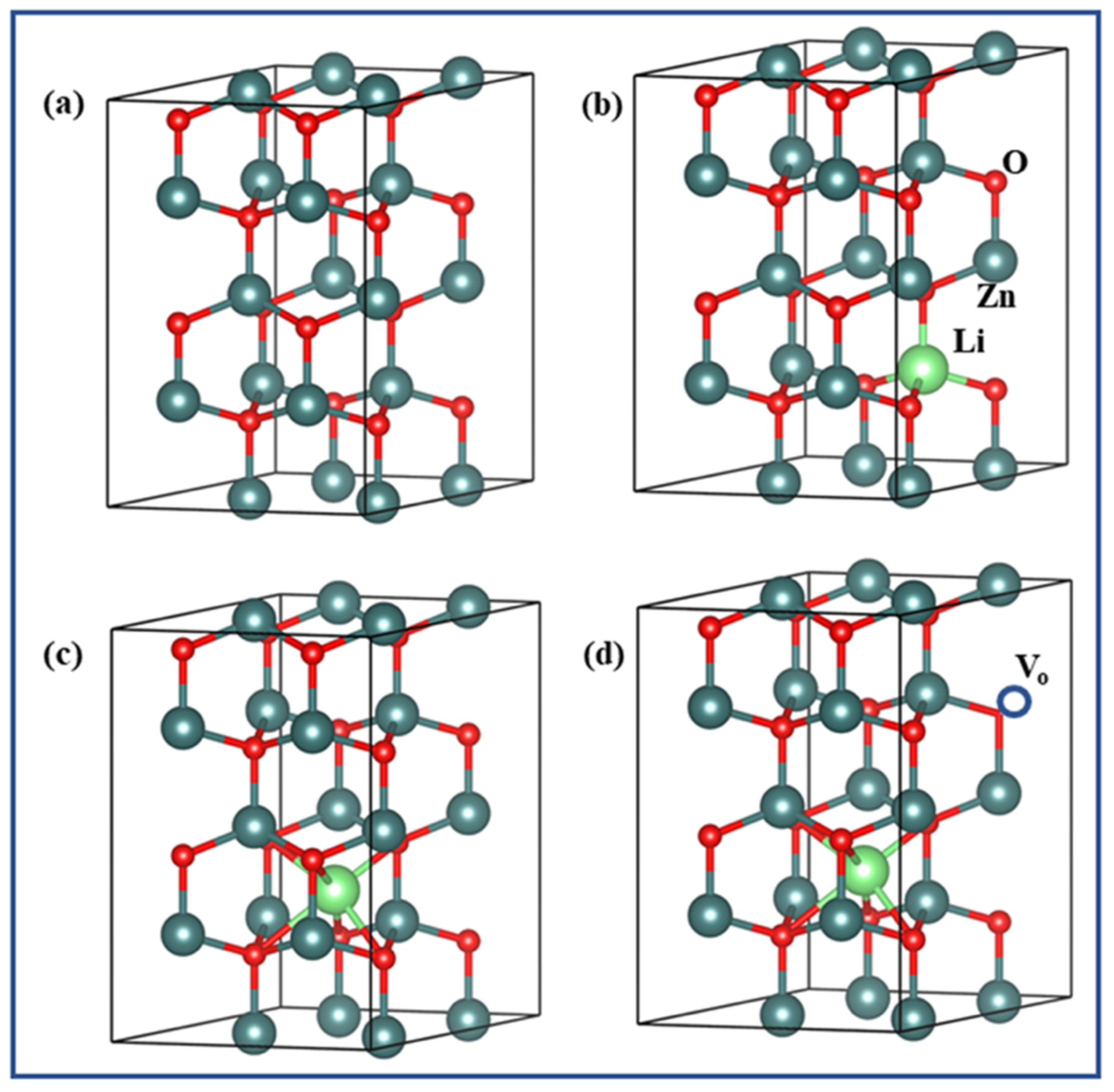
2.1. Synthesis and Characterization of ZnO and Li-Doped ZnO

The cost-effective sol–gel method synthesized pure and Li+ doped ZnO nanocrystalline samples [42]. ZnO is typically prepared by dissolving zinc acetate (CH3COO)2 Zn(2H2O) in deionized water and then adding 60 mL of ethylene glycol monomethyl ether (C3H8O2). For eight hours, we agitated the dissolved transparent solution vigorously over a hot plate (60 °C). Therefore, the fluffy gel was obtained when the produced transparent solution was dried in an oven kept for 2 days at 120 °C. The ZnO nanocrystalline sample was obtained after calcining the fluffy gel at 350 °C for 20 h in air atmosphere. Similarly, Zn1−xLixO nanostructured samples were also generated through the sol–gel method. Lithium nitrate was supplied to the precursor solution in an approximated amount as a dopant, and the rest of the synthesis process remained the same. In this method, calculated amounts of Zinc acetate and Lithium nitrate were used as the precursors and dissolved in the deionized water. Then, the calculated amount of the ethylene glycol monomethyl ether (C3H8O2) was further added to the transparent solution. The dissolved clear solution was heated to 60 °C and agitated vigorously for eight hours before being dried in an oven for 2 days at 120 °C. Finally, the fluffy gel was calcined at 350 °C for 20 h in air ambiance resulting in Zn1−xLixO nanocrystalline samples. X-ray diffractometer (Shimadzu 6000 XRD, Kyoto, Japan) through CuKα radiation source (λ = 1.5406 Å) at 40 kilovolt and 30 mA was utilized to structurally characterize the ready samples. The Rietveld refinement of the XRD patterns to refine structural and microstructural parameters was performed using the software program FullProf.2 k (Version 4.30-April 2008-ILL JRC) suit package. The peaks are modeled in the refinement using the Thompson–Cox–Hastings (TCH) profile function with asymmetry [43]. This asymmetric TCH function separates the effects of strain broadening and particle size in the experimental profiles [44]. All possible instrumental modifications were taken into account when modelling the XRD experimental patterns of the synthesized samples against the Si reference sample. Simulation results are observed in this study after key microstructural and morphological parameters were fine-tuned, including lattice strain, particle size, and shape, etc. The peak parameters (U, V, and W Caglioti parameters) were obtained for the XRD instrument machine using a silicon standard sample and reserved unchanged during the refinement process. Each XRD pattern’s background is linearly interpolated between a set of background locations. Peaks in the XRD pattern are positioned by making a series of zero-error adjustments to the fitting procedure. Minimization and X-ray diffraction (XRD) patterns are inspected with the use of the reliability index parameters Rexp (expected error) and Rwp (weighted residual error).
Diffraction, particle size, and morphology pattern images were captured using a high-resolution transmission electron microscope (HRTEM, JEOL-2100F Tokyo, Japan) functioning at 200 kilovolts. The optical properties of the synthesized nanocrystalline samples were studied using Shimadzu UV-Vis-1800 spectrometer, Kyoto, Japan. Photoluminescence (PL) spectroscopy (PerkinElmer, LS-55, Woodbridge, ON, Canada) measurements of the samples of undoped and Li1+ doped ZnO nanocrystalline were executed with the excitation wavelength of 325–340 nm at room temperature.

2.2. Models and Calculation Methods

The subsequent models were assembled and studied: pristine ZnO supercell with 32 atoms Zn16O16, Zn15LiO16 supercell, Zn16LiinO16 supercell (one Li at interstitial position), and Zn16LiinO15 supercells (one Li and VO one oxygen vacancy). The theoretical calculations were achieved with the generalized gradient approximation (GGA) as instigated in the PWSCF code of the Quantum ESPRESSO integrated package. The Perdew–Burke–Ernzerhof (PBE) scheme designated the exchange–correlation potential. In all the described systems, the GGA + U scheme has been used to correct the band gap energies, and the value of U for the Zn and O atoms are 10 eV and 7 eV, respectively. Zn-3d10 4s2, O-2s22p4, and Li-1s2 2s1 valence electron configurations have been used to construct pseudopotentials. The cut-off energy of the used plane-wave expansion stayed 225 eV with the convergence accuracy of the geometric optimization and energy was 1.0 × 10⁻⁶ eV/atom. The Monkhorst–Pack 5 × 5 × 4 k-point mesh was exploited to estimate first Brillouin zone with a smearing of 0.01 Ry in all the systems.

2.3. Preparation of Membrane Cathode Assembly (MCA)

The cathode consisted of carbon felt (unless otherwise specified, round sheet has an effective diameter of 3 cm). To make ink with a catalyst of cathode, 0.01 mg/cm2 dust of MnO2 (20 wt% MnO2, Sigma-Aldrich, Mumbai, India) and 3 mg/cm2 carbon black Vulcan XC-72 from Cabot Corp of Boston, MA, USA are combined with aqueous solution of 1.2 L of PVA (1% w/v) as the binder at 1:1 acetone–isopropyl of 20 mL [45]. The PVA- MnO2 carbon black aqueous-acetone solution was ultrasonicated for 30 min and then utilized as ink to cover the cathode. On the carbon felt, ink containing a cathode catalyst was applied before being baked at 60°C. In this method, the membrane (ZnO-NPs PVA) is directly bonded to an adjustable carbon felt electrode doped with MnO2 catalyst at 85 °C hot pressing for 5 min; the membrane cathode assembly (MCA) was constructed (Moore Max Ton Hydraulic Press- 800 kPa, Mumbai, India) [46].

2.4. Microbial Fuel Cell Construction and Operation

Five identical single chambered MFCs of the cylindrical type were selected for the experiment with Borosil glass bottles of 500 mL, with a side aperture that is 3 cm in diameter, is attached at the bottom. Anode and cathode electrodes were spaced apart by 4 cm in the hot-pressed MCA (7.07 cm2 by 3 cm in diameter), which is made of PVA-ZnO with catalyst-loaded carbon felt. The MFC consists of an anode on one side and an MCA on the other. The carbon felt makes the 32 cm2 (4 * 4 cm2, both side exposed) anode electrodes free of catalysts. A comparative investigation was conducted utilizing two distinct membranes, native PVA-ZnO (M1) and PVA-ZnO-Li with 0.5 wt% of Li content (M3), in MFCs with the same design. The adequate anolyte volume was 350 mL. Investigations were also conducted into the effects of mixing various amounts of ZnO (0.5, 1.0, 1.5, 2.0 wt%) in PVA-ZnO-Li on the effectiveness of MFC tests.
MFC was employed for the oxygen mass transfer investigation and the biofouling experiment. The single-chambered MFC configuration had a 500 mL manufactured glass container with a bottom side aperture (28 cm2). PEM (PVA-ZnO-Li) was applied while the chamber was clamped. The cathode electrode was a platinum-impregnated tantalum electrode from Titanium Tantalum Products Ltd. Uttar Pradesh, in India, measuring 3 × 5 cm2. Carbon felt, measuring 6 × 4 cm2 as an anode electrode, was used.

2.5. Inoculum and Anolyte

Throughout the investigation, acetate (carbon source) containing synthetic wastewater was used. For all MFCs, the synthetic acetate wastewater’s COD ranged from 4.99 to 5.01 g/L [13]. The initial pH in each MFC was held constant at 7.0. Mixed consortia of anaerobes isolated from the septic tank bottom sludge of Sharda University Noida served as the inoculum. A 1-mm filter was used to separate the inoculum sludge, which was then warmed for 15 min at 100 °C before cooling. The mixed culture was enhanced with designed synthetic wastewater (DSW) and rinsed three times in saline buffer (at a speed of 5000 rpm) before being inoculated and incubated for 48 h at room temperature and 100 rpm. The enhanced culture that resulted from this was injected with feed at a concentration of 2.8 g VSS/L. Before starting the MFC in batch mode, pre-treated mixed microflora was introduced into the anodic compartment. There were several cycles run. The cycle period for each batch was 48 h. After each feeding, 2 min of oxygen-free N2 were used to sparge MFC to maintain an anaerobic microenvironment. Before being fed, the pH of the effluent was adjusted to a target value of 7.0.

2.6. Membrane Analysis

The membrane’s proton conductance was estimated using electrochemical impedance spectroscopy (EIS; ECLab SP 50/150, Bio-logic, Seyssinet-Pariset, France) in the frequency range of 100 kHz to 100 MHz [13]. With a two-chambered test unit composed of plexiglass equipped with a DO probe, the oxygen crossings were calculated in measures of the oxygen diffusion coefficient (Lutron DO-5509, Noida, India). The exact layout was used to evaluate the acetate diffusion coefficient. The density of diffused acetate was determined using a gas chromatograph, India equipped with a flame ionization detector (FID) and a DB-FFAP fused-silica capillary column using nitrogen as the carrier gas.
Calculation of water uptake was performed by measuring the membranes’ weight change after being submerged in water for 24 h, and the ions exchange capacity was calculated using the titrimetric technique [47]. Two Luggin capillary reference electrodes (CH Instruments, Inc., Bee Cave, TX, USA, RE-5B; +0.197 V vs. a standard hydrogen electrode, SHE) were used to quantify the ion transport rate in a two-chambered electro dialytic cell composed of plexiglass with circular test membrane (9.62 cm2 of the exposed surface) [47]. The tensile strength analysis was used to determine the mechanical properties of the manufactured membranes. Standard testing equipment (Tinius Olsen, Norway) scanned a 50 mm 10 mm piece of PEM at a scanning speed of 12.5 mm min−1 to determine its ultimate tensile strength and percentage of extension.

2.7. Analytical Measurements and Calculations: Electrochemical Evaluation of MFC

A data acquisition system (Agilent Technologies, Selangor, Malaysia) was used to record voltage across a constant external resistance (Rext) of 100. Current (I) flowing through the circuit was determined to be in amperes (A) using Ohm’s law (V = I.Rext), where V is the OV measured. According to Equation (1), the MFCs’ total power output was assessed [48]:
P = I × V
The power density curve displayed during polarization was used to calculate the maximum power density produced by MFCs by varying the external resistances from 10 to 10,000 (GEC05R Decade Resistance Box, Bengaluru, India). The slope frequency of the linear section of the voltage vs. current curve was used to determine the internal resistance. After standardizing with the anodic chamber operating volume (Vand, L) according to Equation (2), the evaluation of the volumetric power density (P, W/m3) was conducted.
i d = V and RA ; p d = V and 2 RA

2.8. Analytical Evaluation and Measurement

Both power production and coulombic efficiency were looked at while evaluating the functioning of the MFC. A detailed discussion of measurement and calculation techniques for calculating Coulombic efficiency, power density, current, and electrode potentials, is provided in the accompanying information (SI). A single chamber and sterile reactor that was mixed using a magnetic stirrer bar, the oxygen coefficient of mass transfer (kcm, cm/s) was measured. A partition with a ZnO-NPs PVA membrane, M3 (8 cm × 8 cm), was placed between the cathode and anode chambers of MFC. The cathode was filled with 4.33 g of Na2HPO4, 2.69 g of NaH2PO4H2O, 0.13 g of KCl, 0.31 g of NH4Cl, and a 50 mM phosphate buffer solution in 1000 mL at pH 7. By using N2 gas to purge the anode chamber, the dissolved oxygen (DO) was reduced to zero prior the kcm measurement. The dissolved oxygen of the cathode chamber was kept saturated during the kcm measurement with a constant air supplied by an aquarium pump operating at 2 L/min. The data logger software was used to record the DO concentration at intervals of 15 min for a batch of 48 h. For each chamber’s liquid volume (V), membrane thickness (Lt), cross-sectional area (A), and batch time (t), we were able to determine the diffusion coefficient (DO, cm2/s) and the kinetic constant (kcm) using Equation (1). The oxygen transfer coefficient (kcm, cm/s) was derived using the formula:
kcm = Dcm / Lt
Short circuit currents (Isc) were measured when the cathode and anode were directly attached to the multimeter. The multimeter used was a Precision Mastech Enterprises Co., Hong Kong, Mastech 6000, Kowloon, Hong Kong counts digital multimeter. The current interrupt approach was used to determine the MFCs’ internal resistance. After the MFC reached a stable state for its potential (V) and current output (I), the circuit was opened, causing the cell voltage (VR) to spike suddenly before rising more gradually.
Analyte chemical oxygen demand (COD) values were measured with a COD measuring kit (UV-1900i Spectrophotometer, SHIMADZU, Kyoto, Japan) in accordance with APHA standard procedures. A desktop pH meter was used to keep track of the pH levels. The membrane containing protein content was measured using the Lowry technique. The membrane was retrieved from MFC after 76 days of operation, maintained with 20 mM phosphate in an autoclave buffer, had debris stuck to it scraped off, and was suspended in a Falcon tube with 10 mL of lysis solution for 20 min to aid in protein extraction. After diluting an aliquot of the well-blended mixture with lysis buffer, the SDS solution was added and the whole thing was vortexed. A spectrophotometer was used to test the sample’s absorbance at a wavelength of 750 nm after 30 min.

2.9. Biofilm Formation Studies on ZnO-Impregnated PVA Membrane

The growth media for bacteria (acetate wastewater) was introduced for six batch cycles into the anode chamber of MFCs with ZnO-impregnated PVA membrane after the bacteria had been washed. Using five distinct ZnO-impregnated PVA membranes, we determined and visually compared the microbial cells attached on the membrane towards anode side for each area and average biovolume of cells (PVA as control and ZnO impregnated in PVA at increasing ratios (1.50, 1, 1.00, 0.75, and 0.50 mg/cm2)). Following the completion of each round of the MFC biofilm formation experiment, the anodes were removed and subsequently sliced into pieces measuring roughly 5 mm by 5 mm. A PBS solution containing 0.1 mg/mL, 3 mM propidium iodide (PI) and using PI (SRL, India) was prepared. The biofilms were incubated in the stain solution for 30 min in the dark till stained. The biofilm samples were viewed on a confocal laser scanning microscopy (CLSM; ZeissMeta510; Carl ZEISS, Inc., New York, NY, USA) with a Zeiss dry objective LCI Plan-Neofluar (×20 magnification and numerical aperture of 0.5). Ten different places on each surface were used to analyze the average biovolume of the biofouling. The same process as previously described was used for picture capture and processing. The images were analyzed with the image processing software COMSTAT in Matlab 6.5 (The Math Works, Inc., Natick, MA, USA) to determine the exact biovolume (m3/m2) in the biofouling layer. In each sample, 10 places on each membrane were randomly selected, examined under a microscope, and evaluated. The CLSM image stacks were 3-dimensionally rebuilt using the Imaris program (Imaris Bitplane, Zurich, Switzerland). The average biovolume of cells attached to the membrane (towards the anode-facing side) was computed and assessed for Li-doped ZnO-impregnated PVA membranes at various concentrations [49].

3. Results

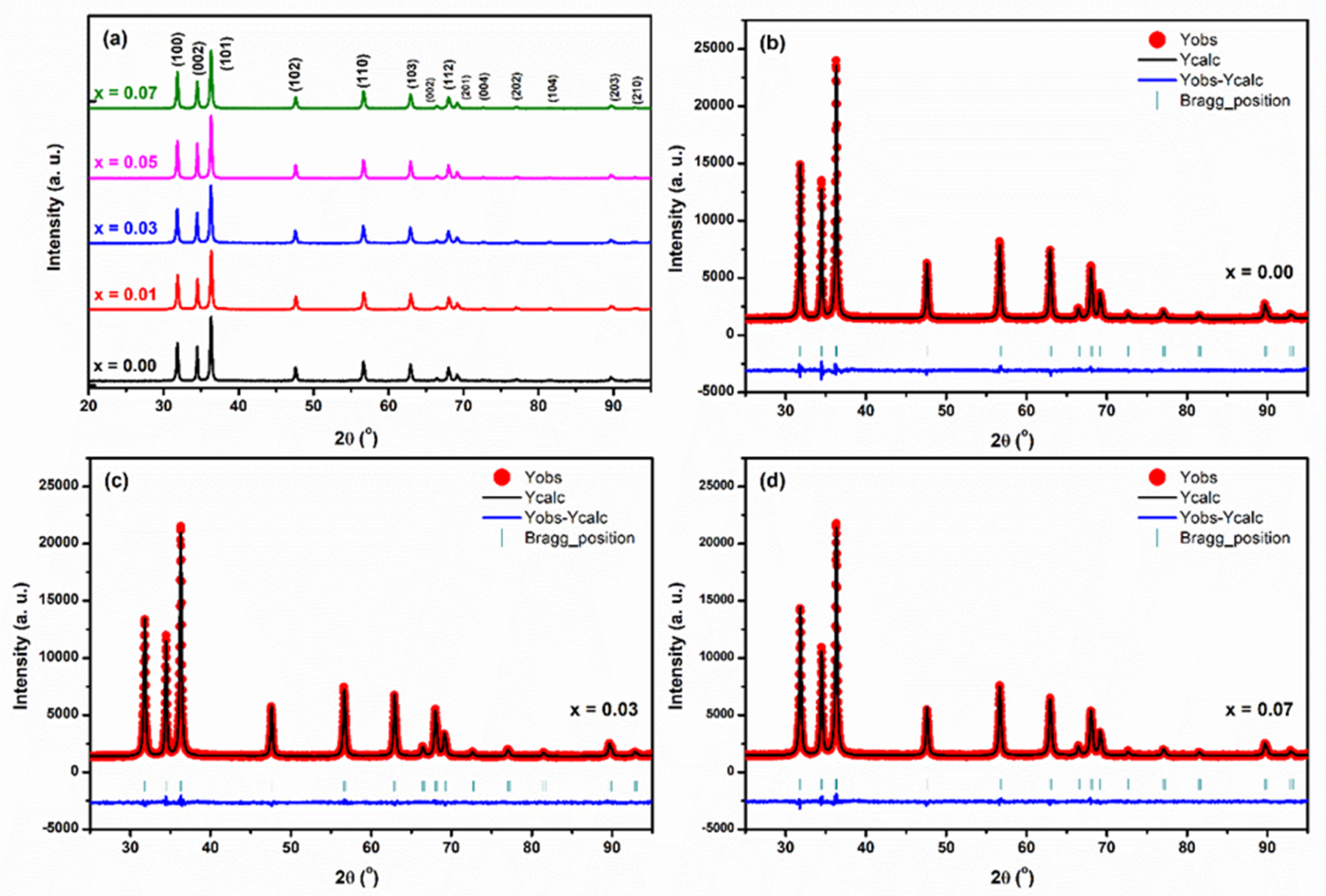
3.1. XRD Rietveld Analysis

Figure 1a shows the patterns of X-ray diffraction of Zn1−xLixO nanocrystalline samples. Zn1−xLixO samples are highly crystalline, and the diffraction patterns specify the development of hexagonal wurtzite crystal structure with the space group P63mc according to the JCPDS card No. 36-1451 [42]. As shown in Figure 1, the peak positions show a slight variation with the Li1+ substitution in ZnO crystalline samples related to the pristine ZnO nanocrystalline sample. ZnO and Li substituted ZnO samples have lattice constants that are consistent with those reported for pure ZnO, as estimated by the authors. The generated Li-doped ZnO nanocrystalline samples have had their phase purity, lattice parameters, and symmetry determined using Rietveld refinement of X-ray diffraction patterns in the space group P63mc (No. 186, Z = 2). Details of the refinement can be finest close-fitted Rietveld refined. X-ray diffraction patterns of the synthesized Zn1−xLixO nanocrystalline sample are revealed in Figure 1b–d. In these XRD patterns, the places of the diffraction Bragg peaks contest fine with the described XRD pattern of nanocrystalline ZnO samples. No other phase consistent with metallic Zn, metallic Li, and the oxides of Li is realized within the XRD detection limit, as shown in Figure 1b–d, and the diffraction Bragg peak positions and background are well suited.
Consequently, the XRD profile refinement approves single phase formation of Zn1−xLixO nanocrystalline samples in the wurtzite (P63mc symmetry) type hexagonal crystal structure and in-depth uniform distribution of Li1+ ions in ZnO nanocrystalline host lattice. The Rietveld refined structural lattice, atomic positional, and fitted reliability parameters are listed in Table 1. The ZnO lattice was found to have a preference for Li atoms, and this preference was confirmed by best-fitting calculations. It was established from a monotonic decrease in the lattice parameter ‘a’ (Å) and the unit cell volume V that the crystal structure of ZnO nanostructured samples is distorted as Li1+ concentration is increased, as seen by the Rietveld refinement of the XRD patterns (Å3). This distortion is due to the movement of the cations along the z-axis and is quantified by the amount by which the anion positional parameter u = [(1/(3(a/c)2)) + (1/4)] deviates from the optimal value of 0.375. The ionic position variable “z” coordinate u parameter of the oxygen atom is initiated to diminution with growing Li concentration in ZnO nanocrystalline samples. Thus, the distortions in bond angle and bond length were clarified. Due to differences in ionic radius and the monovalent state of the Li-ion compared to the divalent Zn-ion, Li doping in ZnO nanostructured crystals deformed the wurtzite structure.
Crystalline samples, whether they are strained, non-strained, or perfect, can be understood by referring to the BVS rule, which stands for the bond valence sum rule [44]. According to the (BVS) rule, the formal charge of the anion (cation) in a perfect crystal is always equal to the sum of the valences of the bonds surrounding the anion (cation). When sufficient degrees of freedom occur in the crystallographic structure, we find this rule to be effective in relieving the tension brought on by the presence of several, independently existing structural units. As a result, the deviation from the BVS rule can be used to quantify the strain between cation and anion bonds in the crystal structure. Table 1 lists the results of bond valence calculations for cations including Zn, Li, and anion O, where Zn-O and Li-O bond lengths are used. With an increase in Li content (from 1 to 7%), the BVS of Zn cation rises from 1.91 to 1.94 and eventually achieves the predicted value of 2. Increases in Li content in ZnO nanocrystalline samples result in a BVS of O that is lower than the predicted value of 2, falling from 1.91 to 1.85. These outcomes show that the Zn cations are underbonded, and the Li cations are over-bonded in this crystal structure; or because the Zn-O bonds are under tension and the Li-O bonds are under compression, the resulting structure is very metastable.

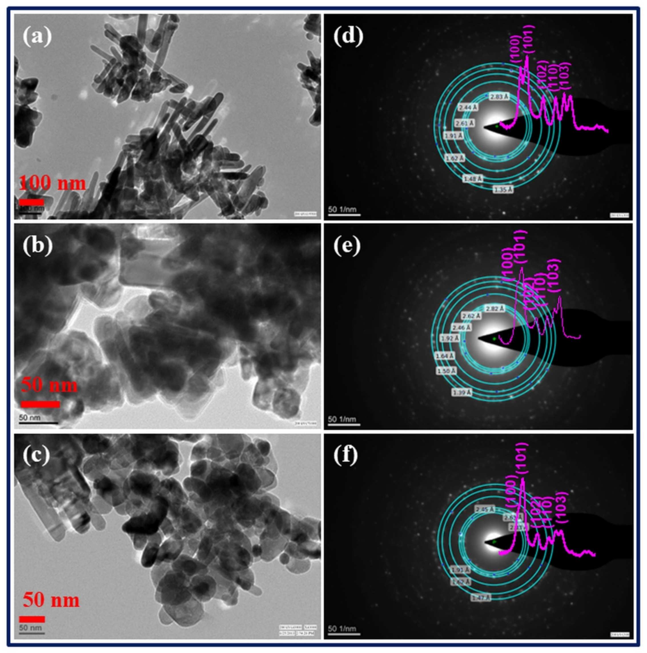
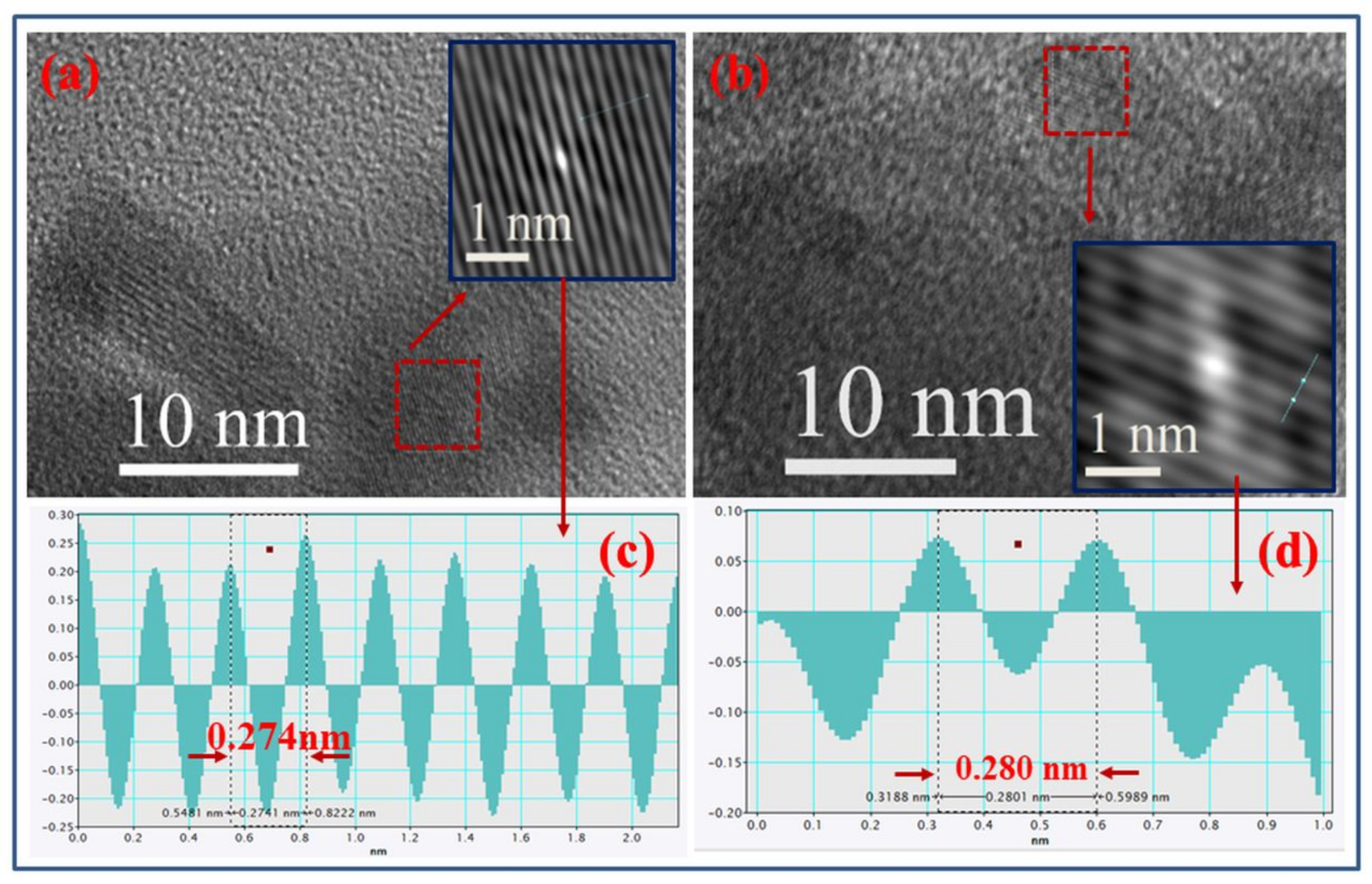
3.2. Analysis through Transmission Electron Microscopy (TEM)

The TEM method was used to characterize the crystallinity, shape, and size of the generated nanostructured samples, among other morphological and crystallographic properties. The low-resolution TEM images of Zn(1−x)LixO: x= 0.0, 0.03, and 0.07 nanostructured materials are shown in Figure 2a–c, respectively. The morphology of pure ZnO samples is that of nanorods, with a diameter of 30 nm and a length of 500 nm; however, as the Li concentration in ZnO nanostructured materials is increased, the nanorods transform into hexagonal-spherical nanoparticles of size 30–50 nm. Additionally, the TEM pictures show that the nanostructured materials get bigger as the Li concentration rises in ZnO. Because of the induction of lattice strain, ionic size mismatches develop. Particle growth is slowed as a result of the system’s lattice stresses, which also improve the nucleation rate. Selected area electron diffraction (SAED), as shown in Figure 2d–f, is also used to investigate the polycrystalline nature of both undoped and Li-doped ZnO nanostructured samples. The SAED shows that polycrystalline samples have the distinctive ring pattern. The simulated ring pattern of SAED of Zn1−xLixO nanostructured with the diffraction intensity of peaks is also displayed in Figure 2d–f. The SAED pattern is in great concurrence with the XRD pattern. The pink curves in Figure 2d–f represent the diffraction intensity ring profile of the selected area electron diffraction patterns using the tool “Diffraction Ring Profiler”. The electron diffraction pattern profiler was unable to resolve the closely spaced rings corresponding to the (110), (002), and (101) peaks, however, giving the right lattice spacing of 2.83 nm, 2.63 nm, and 2.44 nm for the ZnO nanorods. Due to the low resolution of the closely spaced electron diffraction rings, the electron diffraction ring intensity profile is slightly different. This shows the overlapping of the (110), (002), and (101) peaks.
The HRTEM images illustrate that the fine nanostructured samples were very considerably crystallized into single crystals by the specific interplanar spacing. In Figure 3a,b, we see a high-resolution TEM image of a specific region of the Zn (1−x)LixO: x= 0.0, 0.07 samples. The interplanar spacing of the samples is ascertained from the intensity profile of the autocorrelated image of the selected portion by using the Gatan Microscopy Suite software. The autocorrelated images of the selected portion of the x = 0.00 and x = 0.07 samples are shown in the inset of Figure 3a,b. Figure 3c,d exhibit the lattice plane intensity profile pattern resulting in the inset of Figure 3a,b, confirming the interplanar spacing of about 0.274 nm and 0.28 nm, corresponding to the (002) and (100) planes of the ZnO and Zn0.93Li0.03O nanostructured samples, respectively.

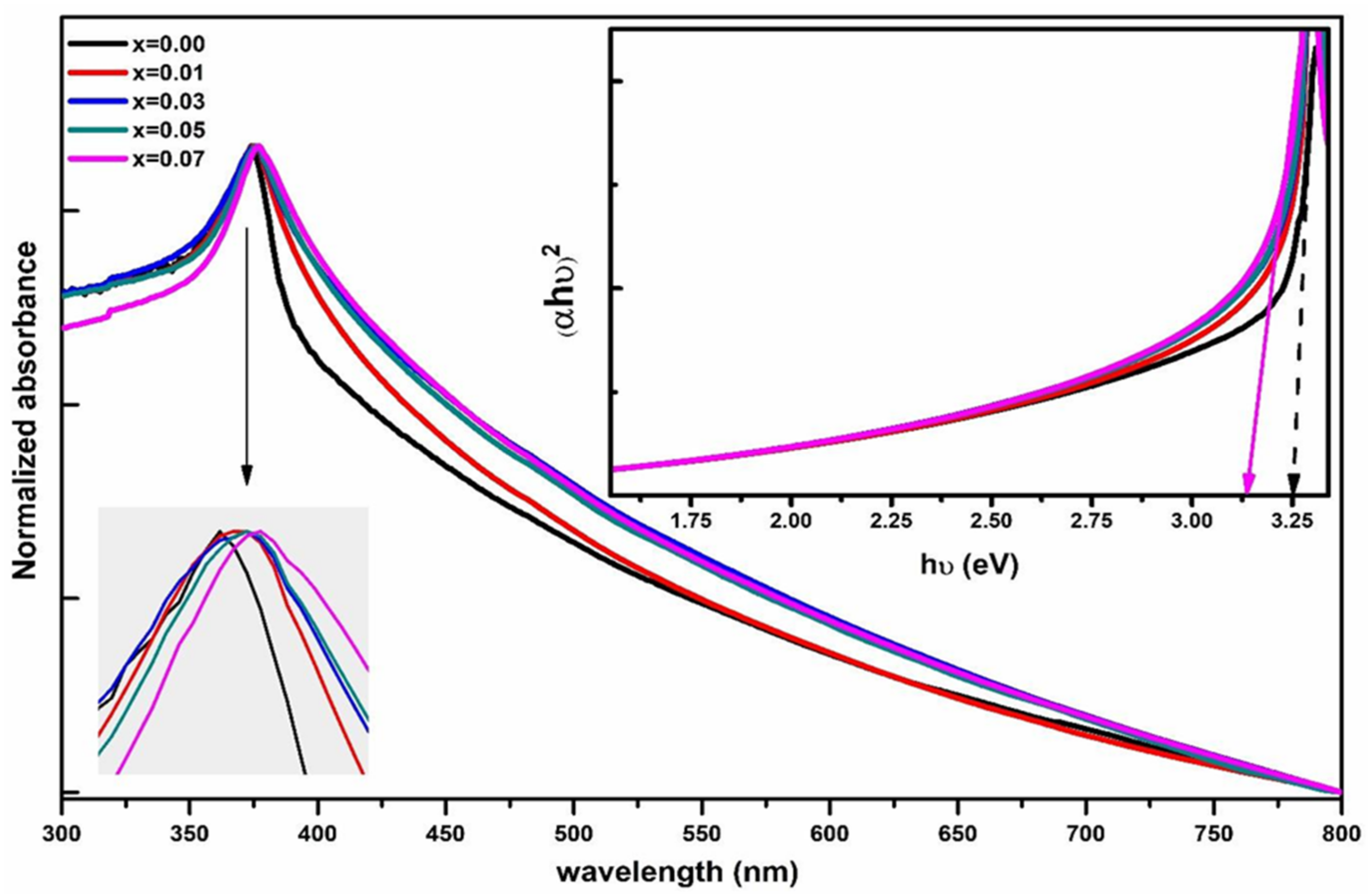
3.3. UV-Visible Spectroscopy

In Figure 4, we can see the UV–visible absorption spectra of Zn1−xLixO nanostructured materials. The nanostructured sample powders were homogeneously dispersed in the ethanol with the help of the bath ultrasonicator for 50–60 min before recording UV–vis spectra. It can be seen in the inset of Figure 4 that the UV–vis absorption spectra of both undoped ZnO nanorods and 7% Li-doped ZnO nanostructured samples have excitonic peaks about 374 nm, which are offset from the intrinsic bandgap absorption peak. These absorbance peaks result from valence-to-conduction band (VB-CB) electron transitions (CB). The optical energy band gap of Zn1−xLixO nanostructured samples has been calculated using the classical Tauc relation:
α h υ = A h υ E g n
where A is a constant, and photon energy is hυ. In this case, the thickness of the cuvette is 1 cm; therefore, the energy band gap is Eg, and the absorption coefficient is given by = (1/d) × ln(1/T), where T is the transmittance, and d is the absorption coefficient. The electronic transition that causes absorption determines whether n is 1/2, 3/2, 2, or 3. Direct transition is possible when n = 1/2, resulting in a direct band gap. The plots of (αhυ)2 versus hυ for Zn1−xLixO nanostructured samples are shown in the inset of Figure 4. It is possible to obtain direct energy band gaps by extrapolating the linear portion of these figures to (αhυ)2 = 0. Undoped ZnO nanoparticles have a band gap of about 3.25 eV, which shrinks with increasing Li doping. The band gap of Zn0.93Li0.07O nanoparticles is around 3.13 eV. Band gap shirking due to Li1+ ion incorporation in ZnO nanoparticles can be seen when compared to those of undoped ZnO nanoparticles. The band gap energy can be lowered by incorporating Li1+ ions into the ZnO lattice, which can generate a shallow level inside the band gap. The DFT theoretical results also confirm the shallow levels inside the bandgap.

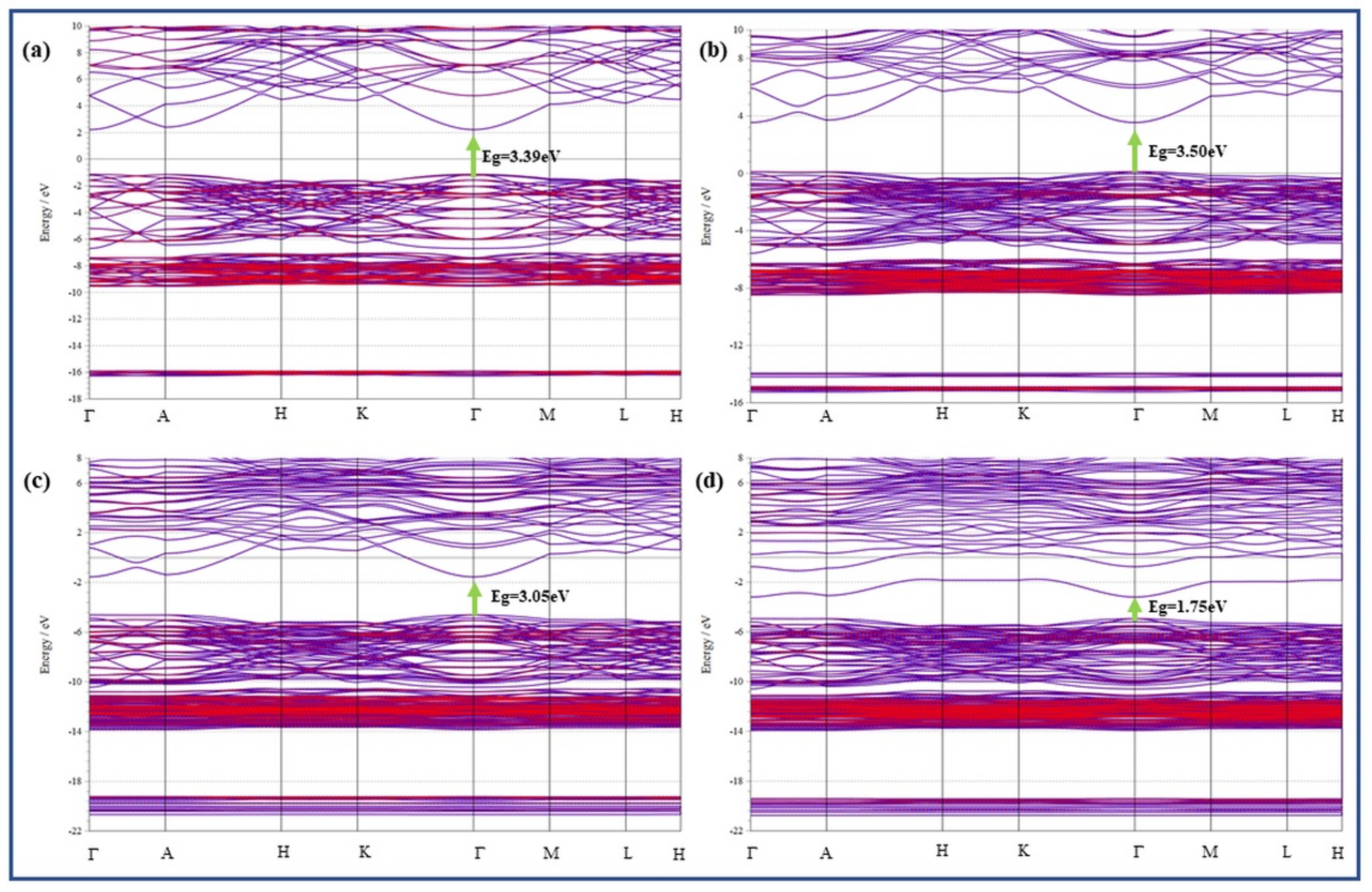
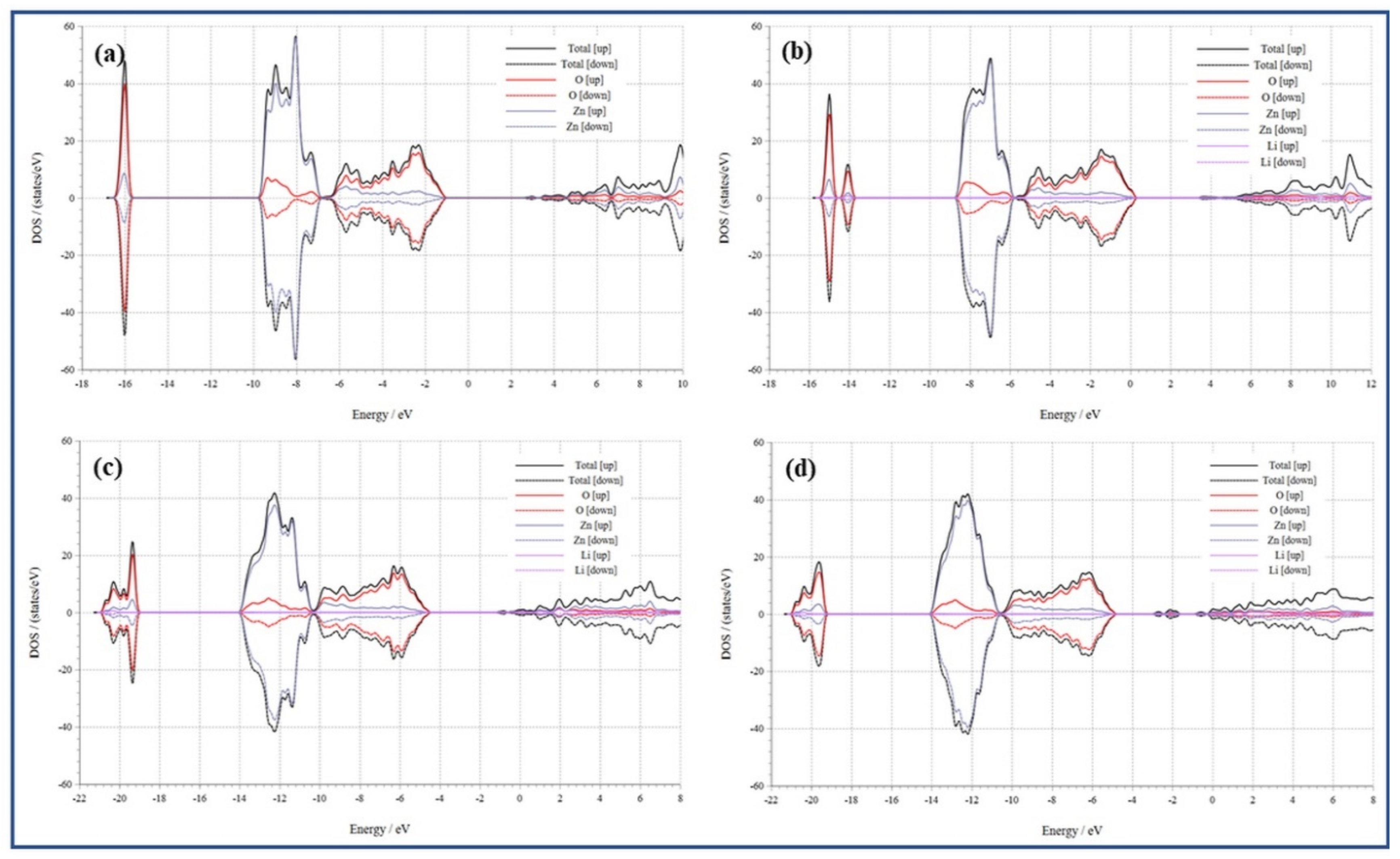
3.4. Analysis of Energy Bandgap Structure:

The subsequent models were made: pure Zn16O16 supercell (2 × 2 × 2), a Li substituted ZnO lattice Zn15LiO16 supercell (one Li at Zn site), Zn16LiinO16 supercells (one Li interstitial Liin), Zn16LiinO15 supercells (one Liin and one VO). The models studied have been shown in Figure 5a–d. Figure 6a–d demonstrate the energy band structures of ZnO, Zn15LiO16, Zn16LiinO16, and Zn16LiinO15, respectively.
Figure 6a displays the 3.39 eV band gap energy of pure ZnO, which is reliable by the experiment reported previously by our group. The outcomes of the theoretical investigations guarantee that the parameters chosen for this study were reasonable. The Fermi level shown in the Figure is at zero-point energy. Figure 6b–d show that the band gaps of Zn15LiO16, Zn16LiinO16 and Zn16LiinO15 are 3.50 eV, 3.05 eV and 2.75 eV, respectively. The findings indicate that, with the exception of the Li substituted ZnO: Zn16LiinO16, the band gaps of Zn16LiinO16 and Zn16LiinO15 systems are narrower than those of pure ZnO systems. Results from theory calculations are reasonably in line with those from experiments.
The density of states (DOS) further explains the system of band gap change. Figure 7a–d displays the density of states (DOS) of pristine ZnO, Zn15LiO15, Zn16LiinO16, and Zn16LiinO15. The conduction band of pure ZnO is shown to be dominated by the Zn 4s, Zn 3p, and O 2p states in Figure 7a. The valence band is mostly provided by the O-2p state, Zn-3p state, and Zn-3d state, and the maximum of the valence band is primarily resolute through the Zn-4s state. The conduction band minimum is resolute through the Zn-4s state. Figure 7b–d displays that the conduction band of Zn15LiO16, Zn15LiinO16, and Zn15LiinO is largely contributed via Zn-4s, Zn-3p, and O-2p states [50]. The Zn-4s state contributes to the lowest conduction band of Zn15LiO16, Zn15LiinO16, and Zn15LiinO15. The Zn-4s state contributes to Zn15LiinO15’s minimal conduction band [51]. The majority of the valence bands in Zn15LiinO15, Zn15LiinO16, and Zn15LiO16 are occupied by the Li-2s, Zn-3d, Zn-3p, Zn-4s, and O-2p states. The O-2p state mainly contributes the maximum valence band of Zn15LiO16, Zn15LiinO16, and Zn15LiinO15. The DOS of Zn15LiO16, like pure ZnO, shows a symmetrical design, as illustrated in Figure 7b; thus, Zn15LiO16 is nonmagnetic. As a result, Zn15LiO16 does not produce an internal magnetic field. The Urbach tailing effect, brought about by hybrid coupling between Zn-4s and Li-2s states in the lowest conduction band, reduces the Zn16LiinO15 band gap. The maximal valence band is mostly unchanged in the meantime. In comparison to undoped ZnO, nonmagnetic Zn15LiinO15 has a greater band gap [52]. The improved hybrid coupling back-bond effect between Zn-4s, Zn-3p, and O-2p states at the minimal conduction band is responsible for this result, whereas the maximum valence band is essentially unaltered [53]. The energy level between the highest valence band and the minimum conduction band is split, and the band gap is shrunk due to the presence of an intrinsic magnetic field in Zn15LiinO16 and Zn15LiinO15.

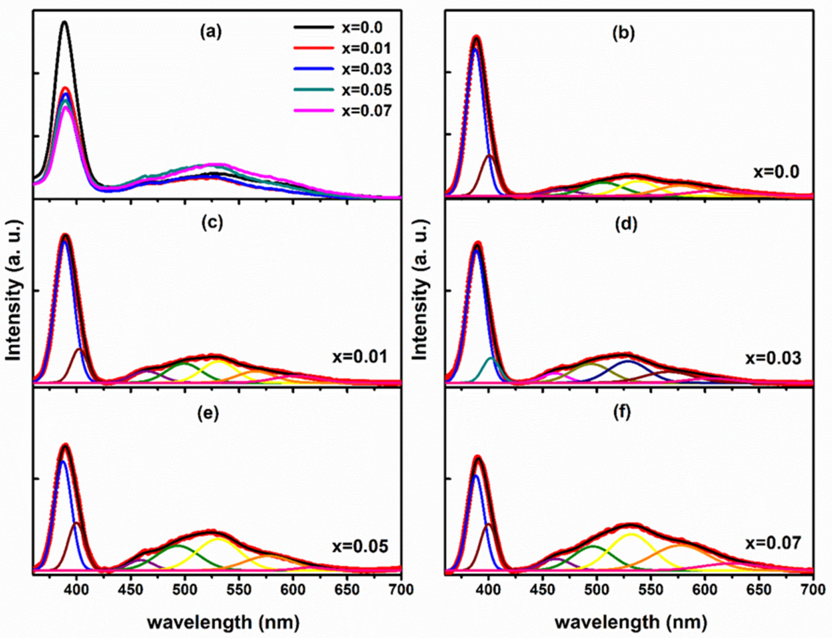
3.5. Photoluminescence Spectroscopy

At ambient temperature, the photoluminescence PL spectra were obtained in the 350–700nm region (Figure 8a), allowing us to investigate the defect-associated emission and the relative fluctuations of the defects in ZnO nanocrystalline samples due to the Li doping. Then, the PL spectra for Zn1−xLixO nanostructured samples were deconvoluted using the peak-fit software with the Gaussian function. Figure 8a shows the PL spectra of Zn1−xLixO nanostructured samples at room temperature. Direct recombination of the free exciton causes the UV emission at 385 nm, and the intensity of this emission is significantly greater than that of the visible luminescence. UV emission exhibits a red shift toward longer wavelengths when Li concentration increases in ZnO nanostructured samples, as seen by a small shift of peak energies toward longer wavelengths. The shifting shows a decrease in bandgap with increasing Li content. Acceptor-doped ZnO typically exhibits a narrowing bandgap, while donor-doped n-type ZnO shows a widening band gap. In detail, ZnO nanostructured samples doped with donor ions displayed a blue shift in the UV emission peak of photoluminescence spectra associated with pristine ZnO nanocrystalline samples. The detected red shift in the ultraviolet emission peak in Li-doped ZnO nanocrystalline samples may be an outcome of getting p-type ZnO nanocrystalline samples. The electrical transport measurements completed by Shakti et al. confirmed the p-type carriers in Li-doped ZnO nanorods. In the visible part of the photoluminescence spectrum, between 440 and 725 nm, the luminescence is so faint that it is scarcely detectable. Broad luminescence pattern in the visible region showed relatively bright green (530 nm) with faint blue emission, yellow luminescence (580 nm), and high orange-red emission (590–700 nm), all attributable to the different defect states present in the pure and Li doped ZnO nanostructured materials (460 nm) [41]. Impurities and imperfections in the interstitial state of negatively charged oxygen ions are depicted by the visible light emission [54,55]. In Figure 8b, the peak corresponding to 520 to 540 nm should arouse by the intrinsic defect of antistites oxygen OZn (2.38 eV) and interstitial oxygen Oi (2.29 eV).
In ZnO nanocrystalline samples, the presence of the visible luminescence bands is currently being discussed. Zn ions at the interstitial (Znin) site are responsible for the violet-blue emission band at 460 nm. Due to the charge transfer process between the metal ion and the defect sites, the weak blue emission observed in Li-doped ZnO nanocrystalline samples should originate from the expanded Zn interstitial defect. Li1+ integration into ZnO nanocrystalline samples has been recently reported to induce green emission via oxygen vacancy (VO). As a result of the recombination of a hole with singly ionized VO defects, it has been postulated that the green band emission observed in the ZnO nanocrystalline sample is caused by these defects. A result of their high activation energy, Li ions cannot replace O in the crystal lattice. It is possible for Li ions to permeate into the interstices between the lattices (Liin). As a consequence, Li1+ ions can form procedure substitutional along with interstitial point defects in the lattice of ZnO; consequently, to preserve the charge balance of ZnO lattice, intrinsic point defects of Oin and VO are formed and co-occur in ZnO nanocrystalline samples. Table 2 shows the conductivity of the PVA-ZnO membrane increases with an increase in the concentration of Li-doping to a certain point. It shows the increment in conductivity till 1.50% (w/w). After increasing the concentration of ZnO-NP doping beyond 1.5%, no increment in conductivity has been observed in the MFCs.

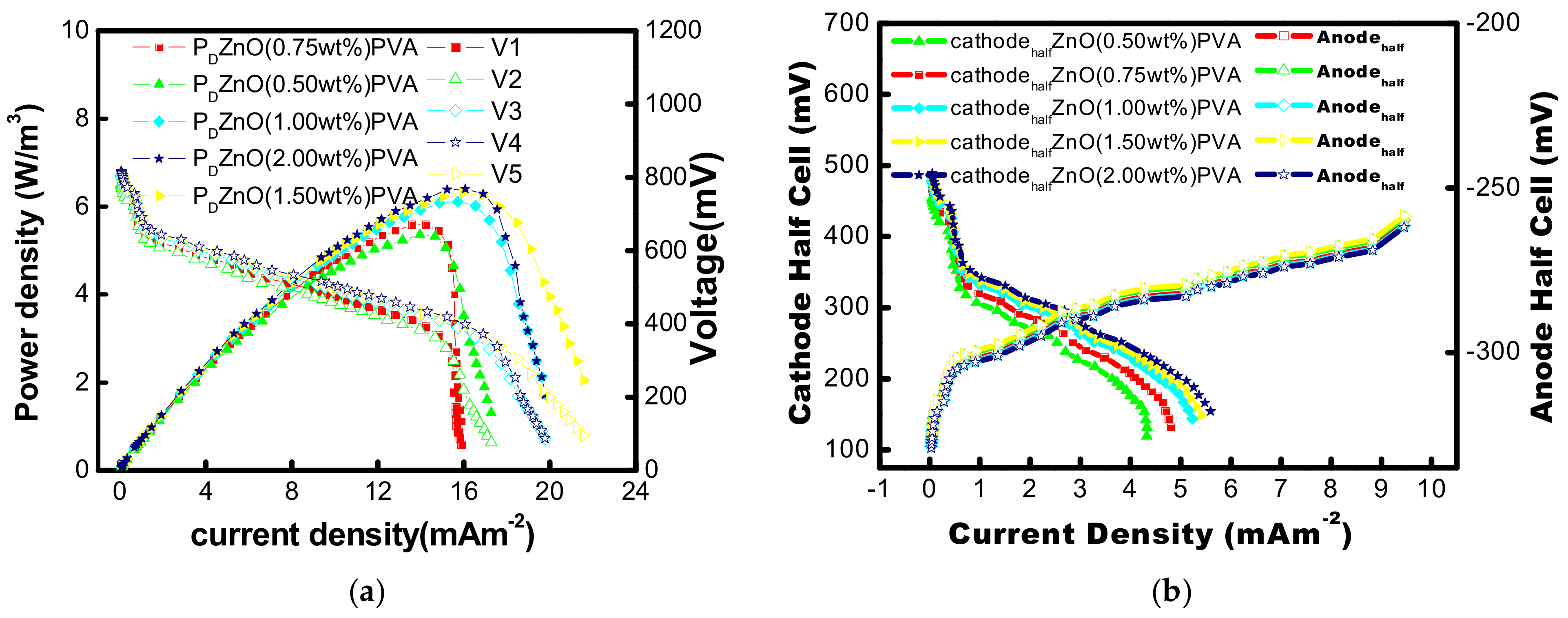
3.6. Performance of PVA-ZnO-Li Membrane in MFC and Oxygen Mass Transfer

Using MFC reactors devoid of any inoculum, the oxygen crossing to the anode from the cathode via the ZnO-PVA membrane was evaluated. The medium solution in the MFC has previously been sparged with nitrogen gas to eliminate dissolved oxygen. The DO probe was placed on top of the MFC to collect data on the DO buildup for 10 h in a sterile medium solution in the anode. Contrarily, in this investigation, the DO concentration rose from 0.1 to 0.37 during 8 h in the case of ZnO-PVA membrane; K cm = 1.4 × 10⁻⁶ cm/s and D cm = 5.6 × 10⁻⁸ cm2/s were found in the MFC with PVA-ZnO-Li. Table 3 gives the comparison of the electrochemical performance of various types of ion exchange membranes in MFCs.

3.7. Voltage Generation

All five single chambered MFCs required two weeks to stabilize under a working condition of batch mode and 48 h of feed cycle time. A gradual rise in current was seen as operating time increased. On the sixteenth day for all sMFCs, the current generation achieved its highest value of 1.76 ± 0.4 mA at the external load of 100 Ω. Seven times in a row, acetate medium was transferred into the anode chamber of the mediator-free MFC, due to which stable power was produced.
Utilizing a variable resistance box with a resistance range of 90k to 10k and measuring the resulting voltage drop, the external resistance of the closed circuit may be adjusted, and polarization curves were produced after nine batch cycles. A total of 15 to 20 min were needed to obtain a steady reading. 1.5% wt ZnO-PVA provided highest volumetric power densities of 6.3 W/m3 according to the power densities measured. PVA without ZnO nanoparticles (as negative control) reached maximum volumetric power densities of 0.80 W/m3, which were 25% and 20% less than ZnO-PVA membrane-based MFC (Figure 9a,b). These findings unequivocally demonstrate that ZnO-PVA demonstrated superior power production. This was explained by ZnO-PVA having an order of magnitude less oxygen permeability. The effectiveness of MFC without ZnO NP in PVA membrane is decreased by the diffusion of oxygen from the cathode chamber to the anode chamber via the separator because some of the substrates are consumed directly by the oxygen instead of transmitting the electrons through the electrode and the circuit with PVA. With the application of various ZnO-NP loaded PVA membrane during the current work, the stable half cells (anode and cathode) are calculated. ZnO nanoparticle loads of 0.50, 0.75, 1.0, 1.5, and 2.00 wt% ZnO nanoparticles are used to observe the effect of ZnO nanoparticle load on the generation of power to PVA in MFCs. The wide variation in the potential of the cathodic half-cell of the microbial fuel cell is listed with different catalyst loads of ZnO nanoparticles in the PVA membrane (Figure 9b). The maximum volumetric power density (Pd,max) of 6.3 w/m3 was observed for 1.50 wt% ZnO-Li. The Pdmax increases to 5.5, 6.0, and 6.2 w/m3 when the concentration of ZnO-Li was increased to 0.75, 1.0, and 1.5 wt% respectively. When the concentration of ZnO-Li is further increased from 1.5 to 2.00 wt%, Pd max was found almost unchanged (around 6.2 w/m3). So, 1.5%wt was found optimum for maximum power output. However, increasing the ZnO nanoparticle concentration from 0 to 0.25 wt% results in a twofold improvement of Pd,max.

3.8. Effect of Li Addition in PVA-ZnO Membrane

The voltage generated in MFCs with PVA-ZnO-Li membrane was observed to research the impact of Li alliance on the general MFC activity in terms of power output and coulombic efficiency, where Li concentrations ranged from 0.0 wt% to 0.9 wt%. It was shown that the performance of MFCs can be considerably impacted by the amount of Li in the membrane (Table 2). The maximum power density of the MFC using the PVA-ZnO membrane without Li was 6.3 W/m3. The maximum volumetric power density increased with an increase in the concentration of Li from 0.0 to 0.3wt%. Additionally, increasing the amount of Li from 0.0 to 0.3 wt% increased coulombic efficiency by 15%. Due to its greater conductivity than the lower concentrations of Li in PVA-ZnO-Li membranes, the 0.3 wt% Li-loaded PVA-ZnO-Li membrane generates more power. The findings indicated that Li addition has a sizable impact on coulombic efficiency. However, when the concentration was further increased from 0.3 wt% to 0.9 wt%, the maximum volumetric power density was shown to decrease. The lower transmembrane potential loss may cause the MFC’s poor performance with the PVA-ZnO membrane without Li or Li at a very high concentration. The positive charge of Li in 0.9 wt% Li on ZnO PVA CEM may affect cation transfer owing to electrostatic repulsion.
Additionally, the concentration of biofouling (microbial cell) on the surface of PVA-ZnO membranes was found greater in Li contents (0.3 wt%) and was much lower than native PVA-ZnO membranes. According to previous research, the buildup of these bacteria and biofoulants causes a thick biofilm to grow on the surface of the CEM, increasing electrical resistance. Most foulants travel toward ion exchange membranes due to their surface charges and electric motilities. Liu et al. demonstrated that the cells lose integrity due to flattening after exposure to Li dispersions. Li has the propensity to cause bacterial cells to experience membrane stress, which causes the cellular structures to be destroyed. Reactive oxygen species (ROS) mediated oxidative stress, for example, was one type of oxidative stress claimed to be mediated by graphene-based materials. With the addition of Li on the PVA-ZnO membrane, less bio-foulant (bacterial cells) was discovered on the anode-facing side of the membrane. Overall, the results show that at an optimum level, the Li blending in the ZnO PVA membrane improved conductivity and decreased biofouling. Table 4 gives the comparison of the CEMs in different type of MFCs.

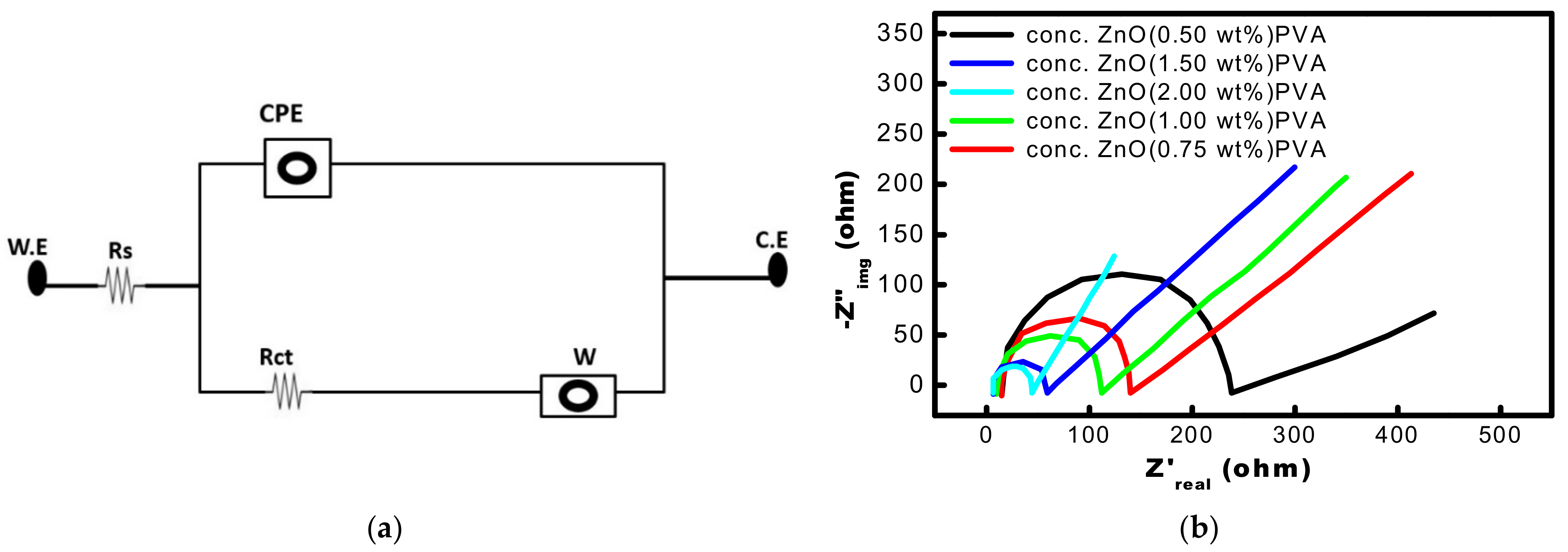
3.9. Electrochemical Impedance Spectroscopy Studies (EIS)

EIS is primarily used to evaluate electrode material quality, biofilm formation, and chemical reaction kinetics. Nyquist plots are used to investigate the electrochemical properties at the electrode interfacial layer (imaginary impedance vs. actual impedance). Internal losses such as diffusion transfer resistance, charge transfer resistance, and ohmic resistance are studied using EIS. This method employed a potentiostat (BioLogic SP150, Seyssinet-Pariset, France), controlled by EC-Lab software, Bio-Logic Seyssinet-Pariset, France to assess a broad frequency range (1 MHz to 100kHz). On Nyquist or Bode graphs, the outcomes of this method are shown. Figure 10a shows an equivalent circuit of MFCs.
The Nyquist plot contrasts original and fictitious impedance. The impedance at various frequencies is represented on the graph (Figure 10b). They conceal the frequency used to record a certain moment, which is a big problem. The Y-axis displays the phase angle and absolute impedance values, while the X-axis plots impedance as a function of frequency. In MFCs, the internal resistance of the system may be expressed as a clearly defined semicircle in the high-frequency region followed by a straight line in the lower-frequency range. The resulting resistance is greatest at the highest frequency point. The diameter of the semicircles may be utilized to calculate the resistance of charge transfer of each electrode (Rct). The Rct value is directly related to the catalyst and reactant or electrolyte interfacial contacts. MFC with a 2.00 wt% ZnO had a lower internal resistance (42.7 Ω), 1.50 wt% ZnO concentration had (47.5 Ω) than MFC with a 0.50 wt% ZnO concentration (223.611 Ω). Like this, as shown in Figure 10, the MFCs with ZnO concentrations of 0.75 wt% and 1.00 wt%, have shown 125 Ω and 102.78 Ω, respectively. There was no significant difference found in MFCs having 1.5% and 2.00 wt% ZnO impregnated PVA membrane.
The components on the various PVA membrane surfaces and the biofilm formation were characterized using CLSM. The quantified results of biofilm formed on 1.5wt% of ZnO-impregnated PVA membranes in MFC experiments are shown in Figure 11.
The COMSTAT software was utilized to evaluate the data shown in Figure 11. Particularly, the minimum cell biomass was detected on the 0.3 wt% Li-ZnO-impregnated PVA compared to the ZnO-impregnated PVA. The minimum and maximum biovolume of the cell of 3.61 μm3/μm2 (±0.84) and 8.62 μm3/μm2 (±0.44) with 0.3 wt% Li-ZnO impregnated PVA and ZnO-PVA without Li, respectively. IMARIS 3D graphics verify COMSTAT’s findings. On 1.5 mg/cm2 ZnO-impregnated PVA, IMARIS shows less cell biomass.

4. Conclusions

In this study, a ZnO-impregnated and Li-doped ZnO-impregnated membrane was used, and different amounts of ZnO were added to PVA membrane of the MFC to improve its electrochemical behavior and increase its proton conductivity. Different proton exchange materials (ZnO NP as ion carrier) were impregnated in the PVA matrix using different concentrations of Li-ZnO (0.5, 0.75, 1.00, 1.5, and 2.00 wt%) as low-cost proton exchangers for MFC applications. Hygroscopic oxides, including ZnO, boost proton transfer because they develop channels via CEM’s microstructural (p-n heterostructure) changes brought on by Li-doping. When Li-ZnO np was impregnated over the PVA membrane, it was observed that the efficiency of current generation increased and was maximum when the concentration of Li-ZnO np was 0.3 wt%. These opened up the possibility of doing more research to reduce the substrate and oxygen crossovers rate, which negatively impacts MFC efficiency. The diffusion coefficient for dissolved oxygen was also calculated for the Li-ZnO-PVA membrane, which showed that the Li-ZnO-PVA membrane can be considered as an alternative to conventional PEMs. It may be concluded that the Li-ZnO-impregnated PVA-based PEM is ideal for potential implementation in MFC due to its characteristics and its low synthesis cost, demonstrating its viability for use in practical MFC systems.

Author Contributions

Conceptualization, S.C., S.P., A.K. and B.S.T.; experiment, A.K., S.C., A.V. and S.P.; writing—original draft preparation, S.C., S.P. and M.K.; writing—review, A.V., N.R., M.K., S.C., S.P. and B.S.T.; editing, S.C., S.P., B.S.T. and S.G.P.; supervision, S.C., S.P., B.S.T. and S.G.P. All authors have read and agreed to the published version of the manuscript.

Funding

This research received no external funding.

Institutional Review Board Statement

Not applicable.

Informed Consent Statement

Not applicable.

Data Availability Statement

Not applicable.

Acknowledgments

S.C. thanks Science and Engineering Study Board (SERB) for funding this research (TAR/2019/000210). Life Sciences Research Board, Defense Research and Development Organization and Department of Science and Technology contributed to this study. S.P. and S.C. appreciate Sharda University Instrumentation.

Conflicts of Interest

The authors have no known financial or personal interest that might have influenced this article.

References

  1. Renewable Energy Road Map—Renewable Energies in the 21st Century: Building a More Sustainable Future—Policies. Available online: https://www.iea.org/policies/4745-renewable-energy-road-map-renewable-energies-in-the-21st-century-building-a-more-sustainable-future (accessed on 5 November 2022).
  2. Sonune, A.; Ghate, R. Developments in Wastewater Treatment Methods. Desalination 2004, 167, 55–63. [Google Scholar] [CrossRef]
  3. Bhowmick, G.D.; Das, S.; Ghangrekar, M.M.; Mitra, A.; Banerjee, R. Improved Wastewater Treatment by Combined System of Microbial Fuel Cell with Activated Carbon/TiO2 Cathode Catalyst and Membrane Bioreactor. J. Inst. Eng. India Ser. A 2019, 100, 675–682. [Google Scholar] [CrossRef]
  4. Ashmath, S.; Kwon, H.-J.; Peera, S.G.; Lee, T.G. Solid-State Synthesis of Cobalt/NCS Electrocatalyst for Oxygen Reduction Reaction in Dual Chamber Microbial Fuel Cells. Nanomaterials 2022, 12, 4369. [Google Scholar] [CrossRef] [PubMed]
  5. Chakraborty, I.; Das, S.; Dubey, B.K.; Ghangrekar, M.M. High-Density Polyethylene Waste-Derived Carbon as a Low-Cost Cathode Catalyst in Microbial Fuel Cell. Int. J. Environ. Res. 2021, 15, 1085–1096. [Google Scholar] [CrossRef]
  6. Logan, B.E.; Regan, J.M. Microbial Fuel Cells—Challenges and Applications. Environ. Sci. Technol. 2006, 40, 5172–5180. [Google Scholar] [CrossRef] [PubMed] [Green Version]
  7. Xu, J.; Gao, P.; Zhao, T.S. Non-Precious Co3O4 Nano-Rod Electrocatalyst for Oxygen Reduction Reaction in Anion-Exchange Membrane Fuel Cells. Energy Environ. Sci. 2012, 5, 5333–5339. [Google Scholar] [CrossRef]
  8. Tian, F.; Zhong, S.; Nie, W.; Zeng, M.; Chen, B.; Liu, X. Multi-Walled Carbon Nanotubes Prepared with Low-Cost Fe-Al Bimetallic Catalysts for High-Rate Rechargeable Li-Ion Batteries. J. Solid State Electrochem. 2020, 24, 667–674. [Google Scholar] [CrossRef]
  9. Canuto de Almeida e Silva, T.; Bhowmick, G.D.; Ghangrekar, M.M.; Wilhelm, M.; Rezwan, K. SiOC-Based Polymer Derived-Ceramic Porous Anodes for Microbial Fuel Cells. Biochem. Eng. J. 2019, 148, 29–36. [Google Scholar] [CrossRef]
  10. Haddadi, S.; Nabi-Bidhendi, G.; Mehrdadi, N. Nitrogen Removal from Wastewater through Microbial Electrolysis Cells and Cation Exchange Membrane. J. Environ. Health Sci. Eng. 2014, 12, 48. [Google Scholar] [CrossRef] [Green Version]
  11. Peera, S.G.; Thandavarayan, M.; Chao, L.; Shaik, A.; Tae, G.L.; Zhongqing, J.; Shun, M. A review on carbon and non-precious metal based cathode catalysts in microbial fuel cells. Int. J. Hydrog. Energy 2021, 46, 3056–3089. [Google Scholar] [CrossRef]
  12. Martinelli, A.; Matic, A.; Jacobsson, P.; Börjesson, L.; Navarra, M.A.; Fernicola, A.; Panero, S.; Scrosati, B. Structural Analysis of PVA-Based Proton Conducting Membranes. Solid State Ion. 2006, 177, 2431–2435. [Google Scholar] [CrossRef]
  13. Adam, M.R.; Hassan, A.A.M.; Othman, M.H.D.; Puteh, M.H.; Ismail, A.F.; Rahman, M.A.; Jaafar, J. Fabrication and characterization of hybrid poly (vinyl alcohol) based proton exchange membrane for energy generation from wastewater in microbial fuel cell system. Int. J. Energy Res. 2022, 46, 23418–23432. [Google Scholar] [CrossRef]
  14. Devanathan, R. Recent Developments in Proton Exchange Membranes for Fuel Cells. Energy Environ. Sci. 2008, 1, 101–119. [Google Scholar] [CrossRef]
  15. Miao, D.; Hu, H.; Gan, L. Fabrication of High Infrared Reflective Al-Doped ZnO Thin Films through Electropulsing Treatment for Solar Control. J. Alloys Compd. 2015, 639, 400–405. [Google Scholar] [CrossRef]
  16. Ahilan, V.; Bhowmick, G.D.; Ghangrekar, M.M.; Wilhelm, M.; Rezwan, K. Tailoring Hydrophilic and Porous Nature of Polysiloxane Derived Ceramer and Ceramic Membranes for Enhanced Bioelectricity Generation in Microbial Fuel Cell. Ionics 2019, 25, 5907–5918. [Google Scholar] [CrossRef]
  17. Ahilan, V.; de Barros, C.C.; Bhowmick, G.D.; Ghangrekar, M.M.; Murshed, M.M.; Wilhelm, M.; Rezwan, K. Microbial Fuel Cell Performance of Graphitic Carbon Functionalized Porous Polysiloxane Based Ceramic Membranes. Bioelectrochemistry 2019, 129, 259–269. [Google Scholar] [CrossRef]
  18. Choi, K.J.; Jang, H.W. One-Dimensional Oxide Nanostructures as Gas-Sensing Materials: Review and Issues. Sensors 2010, 10, 4083–4099. [Google Scholar] [CrossRef] [Green Version]
  19. Fan, L.; Wang, C.; Chen, M.; Zhu, B. Recent Development of Ceria-Based (Nano)Composite Materials for Low Temperature Ceramic Fuel Cells and Electrolyte-Free Fuel Cells. J. Power Sources 2013, 234, 154–174. [Google Scholar] [CrossRef]
  20. Qiao, Z.; Xia, C.; Cai, Y.; Afzal, M.; Wang, H.; Qiao, J.; Zhu, B. Electrochemical and Electrical Properties of Doped CeO2-ZnO Composite for Low-Temperature Solid Oxide Fuel Cell Applications. J. Power Sources 2018, 392, 33–40. [Google Scholar] [CrossRef]
  21. Xia, C.; Qiao, Z.; Feng, C.; Kim, J.-S.; Wang, B.; Zhu, B. Study on Zinc Oxide-Based Electrolytes in Low-Temperature Solid Oxide Fuel Cells. Materials 2017, 11, 40. [Google Scholar] [CrossRef]
  22. Xia, C.; Mi, Y.; Wang, B.; Lin, B.; Chen, G.; Zhu, B. Shaping Triple-Conducting Semiconductor BaCo0.4Fe0.4Zr0.1Y0.1O3-δ into an Electrolyte for Low-Temperature Solid Oxide Fuel Cells. Nat. Commun. 2019, 10, 1707. [Google Scholar] [CrossRef] [PubMed] [Green Version]
  23. Li, Y.; Rui, Z.; Xia, C.; Anderson, M.; Lin, Y.S. Performance of Ionic-Conducting Ceramic/Carbonate Composite Material as Solid Oxide Fuel Cell Electrolyte and CO2 Permeation Membrane. Catal. Today 2009, 148, 303–309. [Google Scholar] [CrossRef]
  24. Thangadurai, V.; Weppner, W. Recent Progress in Solid Oxide and Lithium Ion Conducting Electrolytes Research. Ionics 2006, 12, 81–92. [Google Scholar] [CrossRef] [Green Version]
  25. Wu, J.; Zhu, B.; Mi, Y.; Shih, S.-J.; Wei, J.; Huang, Y. A Novel Core–Shell Nanocomposite Electrolyte for Low Temperature Fuel Cells. J. Power Sources 2012, 201, 164–168. [Google Scholar] [CrossRef]
  26. Accardo, G.; Ferone, C.; Cioffi, R. Influence of Lithium on the Sintering Behavior and Electrical Properties of Ce0.8Gd0.2O1.9 for Intermediate-Temperature Solid Oxide Fuel Cells. Energy Technol. 2016, 4, 409–416. [Google Scholar] [CrossRef]
  27. Yi, J.B.; Lim, C.C.; Xing, G.Z.; Fan, H.M.; Van, L.H.; Huang, S.L.; Yang, K.S.; Huang, X.L.; Qin, X.B.; Wang, B.Y.; et al. Ferromagnetism in Dilute Magnetic Semiconductors through Defect Engineering: Li-Doped ZnO. Phys. Rev. Lett. 2010, 104, 137201. [Google Scholar] [CrossRef]
  28. Zeng, Y.-J.; Ye, Z.-Z.; Xu, W.-Z.; Chen, L.-L.; Li, D.-Y.; Zhu, L.-P.; Zhao, B.-H.; Hu, Y.-L. Realization of P-Type ZnO Films via Monodoping of Li Acceptor. J. Cryst. Growth 2005, 283, 180–184. [Google Scholar] [CrossRef]
  29. Acharya, A.; Bhattacharya, K.; Kumar Ghosh, C.; Narayan Biswas, A.; Bhattacharya, S. Charge Carrier Transport and Electrochemical Stability of Li2O Doped Glassy Ceramics. Mater. Sci. Eng. B 2020, 260, 114612. [Google Scholar] [CrossRef]
  30. Bhattacharya, S.; Acharya, A.; Biswas, D.; Das, A.S.; Singh, L.S. Conductivity Spectra of Lithium Ion Conducting Glassy Ceramics. Phys. B Condens. Matter. 2018, 546, 10–14. [Google Scholar] [CrossRef]
  31. Bhattacharya, S.; Acharya, A.; Das, A.S.; Bhattacharya, K.; Ghosh, C.K. Lithium Ion Conductivity in Li2O–P2O5–ZnO Glass-Ceramics. J. Alloys Compd. 2019, 786, 707–716. [Google Scholar] [CrossRef]
  32. Thapa, B.S.; Kim, T.; Pandit, S.; Song, Y.E.; Afsharian, Y.P.; Rahimnejad, M.; Kim, J.R.; Oh, S.-E. Overview of Electroactive Microorganisms and Electron Transfer Mechanisms in Microbial Electrochemistry. Bioresour. Technol. 2022, 347, 126579. [Google Scholar] [CrossRef]
  33. Thapa, B.S.; Pandit, S.; Patwardhan, S.B.; Tripathi, S.; Mathuriya, A.S.; Gupta, P.K.; Lal, R.B.; Tusher, T.R. Application of Microbial Fuel Cell (MFC) for Pharmaceutical Wastewater Treatment: An Overview and Future Perspectives. Sustainability 2022, 14, 8379. [Google Scholar] [CrossRef]
  34. Li, W.-W.; Sheng, G.-P.; Liu, X.-W.; Yu, H.-Q. Recent Advances in the Separators for Microbial Fuel Cells. Bioresour. Technol. 2011, 102, 244–252. [Google Scholar] [CrossRef]
  35. Khan, M.M.A.; Rafiuddin, I. PVC Based Polyvinyl Alcohol Zinc Oxide Composite Membrane: Synthesis and Electrochemical Characterization for Heavy Metal Ions. J. Ind. Eng. Chem. 2013, 19, 1365–1370. [Google Scholar] [CrossRef]
  36. Otaibi, A.A.; Patil, M.B.; Rajamani, S.B.; Mathad, S.N.; Patil, A.Y.; Amshumali, M.K.; Shaik, J.P.; Asiri, A.M.; Khan, A. Development and Testing of Zinc Oxide Embedded Sulfonated Poly (Vinyl Alcohol) Nanocomposite Membranes for Fuel Cells. Crystals 2022, 12, 1739. [Google Scholar] [CrossRef]
  37. Asadpour, S.; Raeisi Vanani, A.; Kooravand, M.; Asfaram, A. A Review on Zinc Oxide/Poly(Vinyl Alcohol) Nanocomposites: Synthesis, Characterization and Applications. J. Clean. Prod. 2022, 362, 132297. [Google Scholar] [CrossRef]
  38. Abdullah, O.; Al-Salman, Y.; Tahir, D.; Jamal, G.; Taha, H.; Mohamad, A.; Azawy, A. Effect of ZnO Nanoparticle Content on the Structural and Ionic Transport Parameters of Polyvinyl Alcohol Based Proton-Conducting Polymer Electrolyte Membranes. Membranes 2021, 11, 163. [Google Scholar] [CrossRef]
  39. Tiwari, B.R.; Norri, M.T.; Ghangrekar, M.M. A novel low cost polyvinyl alcohol-Nafion-borosilicate membrane separator for microbial fuel cell. Mater. Chem. Phys. 2016, 182, 86–93. [Google Scholar] [CrossRef]
  40. Majumdar, S.; Banerji, P. Effect of Li Incorporation on the Structural and Optical Properties of ZnO. Superlattices Microstruct. 2009, 45, 583–589. [Google Scholar] [CrossRef]
  41. Shakti, N.; Devi, C.; Patra, A.K.; Gupta, P.S.; Kumar, S. Lithium Doping and Photoluminescence Properties of ZnO Nanorods. AIP Adv. 2018, 8, 015306. [Google Scholar] [CrossRef]
  42. Chauhan, S.; Kumar, M.; Chhoker, S.; Katyal, S.C.; Awana, V.P.S. Structural, Vibrational, Optical and Magnetic Properties of Sol–Gel Derived Nd Doped ZnO Nanoparticles. J. Mater. Sci. Mater. Electron. 2013, 24, 5102–5110. [Google Scholar] [CrossRef]
  43. Popa, N.C. The (Hkl) Dependence of Diffraction-Line Broadening Caused by Strain and Size for All Laue Groups in Rietveld Refinement. J. Appl. Cryst. 1998, 31, 176–180. [Google Scholar] [CrossRef]
  44. Alonso, J.; Martínez-Lope, M.; García-Muñoz, J.L.; Fernández-Díaz, M. A Structural and Magnetic Study of the Defect Perovskite LaNiO2.5 from High-Resolution Neutron Diffraction Data. J. Phys. Condens. Matter 1999, 9, 6417. [Google Scholar] [CrossRef]
  45. Pandit, S.; Khilari, S.; Bera, K.; Pradhan, D.; Das, D. Application of PVA–PDDA Polymer Electrolyte Composite Anion Exchange Membrane Separator for Improved Bioelectricity Production in a Single Chambered Microbial Fuel Cell. Chem. Eng. J. 2014, 257, 138–147. [Google Scholar] [CrossRef]
  46. Khilari, S.; Pandit, S.; Ghangrekar, M.M.; Pradhan, D.; Das, D. Graphene Oxide-Impregnated PVA–STA Composite Polymer Electrolyte Membrane Separator for Power Generation in a Single-Chambered Microbial Fuel Cell. Ind. Eng. Chem. Res. 2013, 52, 11597–11606. [Google Scholar] [CrossRef]
  47. Neethu, B.; Ghangrekar, M.M. Electricity Generation through a Photo Sediment Microbial Fuel Cell Using Algae at the Cathode. Water Sci. Technol. 2017, 76, 3269–3277. [Google Scholar] [CrossRef]
  48. Bhowmick, G.D.; Ghangrekar, M.M.; Banerjee, R. Improved wastewater treatment by using integrated microbial fuel cell-membrane bioreactor system along with ruthenium/activated carbon cathode catalyst to enhance bio-energy recovery. In Climate Impacts on Water Resources in India: Environment and Health; Water Science and Technology Library; Pandey, A., Mishra, S.K., Kansal, M.L., Singh, R.D., Singh, V.P., Eds.; Springer International Publishing: Cham, Switzerland, 2021; pp. 183–192. ISBN 978-3-030-51427-3. [Google Scholar]
  49. Pandit, S.; Shanbhag, S.; Mauter, M.; Oren, Y.; Herzberg, M. Influence of Electric Fields on Biofouling of Carbonaceous Electrodes. Environ. Sci. Technol. 2017, 51, 10022–10030. [Google Scholar] [CrossRef]
  50. Hou, Q.; Liu, Y. Effect of Li Doping and Point Vacancy on Photocatalytic Properties and Mechanism of ZnO. Chem. Phys. 2020, 531, 110657. [Google Scholar] [CrossRef]
  51. Ma, X.; Wu, Y.; Lv, Y. Correlation Effects on Lattice Relaxation and Electronic Structure of ZnO within the GGA+ U Formalism. J. Phys. Chem. C 2013, 117, 26029–26039. [Google Scholar] [CrossRef]
  52. Honglin, L.; Yingbo, L.; Jinzhu, L.; Ke, Y. First-Principles Study of p-Type Conductivity of N-Al/Ga/In Co-Doped ZnO. Phys. Scr. 2015, 90, 025803. [Google Scholar] [CrossRef]
  53. Wardle, M.; Goss, J.; Briddon, P. Theory of Li in ZnO: A Limitation for Li-Based p-Type Doping. Phys. Rev. B 2005, 71, 155205. [Google Scholar] [CrossRef]
  54. Shalim, S.; Atta ur Rehman, S.; Musa, M.C.; Mehmet, A.G. Complex Impedance Analyses of Li doped ZnO Electrolyte Materials. Sci. Rep. 2020, 10, 8228. [Google Scholar]
  55. Panigrahy, B.; Aslam, M.; Misra, D.S.; Ghosh, M.; Bahadur, D. Defect-Related Emissions and Magnetization Properties of ZnO Nanorods. Adv. Funct. Mater. 2010, 20, 1161–1165. [Google Scholar] [CrossRef]
  56. Bandaru, S.R.; Behera, M.; Ghangrekar, M. Performance and Economics of Low Cost Clay Cylinder Microbial Fuel Cell for Wastewater Treatment. In Proceedings of the World Renewable Energy Congress-Sweden, Linköping, Sweden, 8–13 May 2011; pp. 1189–1196. [Google Scholar]
  57. Nair, R.; Seetharaman, B.; Renganathan, K.; Venkatraman, K. Performance of Salt-Bridge Microbial Fuel Cell at Various Agarose Concentrations Using Hostel Sewage Waste as Substrate. Int. J. Adv. Res. Technol. 2013, 2, 326. [Google Scholar]
  58. Moharir, P.V.; Tembhurkar, A.R. Effect of Recirculation on Bioelectricity Generation Using Microbial Fuel Cell with Food Waste Leachate as Substrate. Int. J. Hydrog. Energy 2018, 43, 10061–10069. [Google Scholar] [CrossRef]
  59. Bhowmick, G.D.; Dhar, D.; Ghangrekar, M.M.; Banerjee, R. TiO2-Si- or SrTiO3-Si-Impregnated PVA–Based Low-Cost Proton Exchange Membranes for Application in Microbial Fuel Cell. Ionics 2020, 26, 6195–6205. [Google Scholar] [CrossRef]
Figure 1. (a) XRD patterns of Zn1−xLixO nanocrystalline samples calcined at 350 °C. Rietveld refined XRD data of Zn1−xLixO nanocrystalline samples. (b) x = 0.00, (c) x = 0.03 and (d) x = 0.07.
Membranes 13 00055 g001
Figure 2. (ac) TEM images of Zn1−xLixO nanostructured samples (a) x = 0.00, (b) x = 0.03 and (c) x = 0.07. (df) SAED Pattern Zn1−xLixO nanostructured samples, (d) x = 0.00, (e) x = 0.05 and (f) 0.07 sample.
Membranes 13 00055 g002
Figure 3. High-resolution TEM image of Zn(1−x)LixO nanocrystalline samples (a) x = 0.0 and (b) x = 0.07 samples. The inset of (a,b) represents the autocorrelated images of the selected portion of the images. The intensity profile of the autocorrelated images used to measure the interplanar distance for (c) x = 0.0 corresponding to the (002) plane and (d) x = 0.07 corresponding to the plane (100).
Membranes 13 00055 g003
Figure 4. UV–visible absorbance spectra of Zn1−xLixO nanostructured samples. Inset showed the Tauc plots of the absorbance spectra of Zn1−xLixO nanostructured samples.
Membranes 13 00055 g004
Figure 5. Researched ZnO models (Li atom-green ball, Zn atom-dark sky ball, and O atom-red ball): (a) Zn16O16, (b) Zn15LiO16, (c) Zn16LiinO16, and (d) Zn16LiinO15. Vo = oxygen vacancy.
Membranes 13 00055 g005
Figure 6. Band structures of (a) Zn16O16, (b) Zn15LiO16, (c) Zn16LiinO16 and (d) Zn16LiinO15.
Membranes 13 00055 g006
Figure 7. Density of states for (a) Zn16O16, (b) Zn15LiO16, (c) Zn16LiinO16, and (d) Zn16LiinO15.
Membranes 13 00055 g007
Figure 8. (a) Photoluminescence spectra of Zn1−xLixO nanostructured samples. (bf) Deconvoluted photoluminescence spectra of Zn1−xLixO nanostructured samples.
Membranes 13 00055 g008
Figure 9. (a) The polarization curve of MFCs loaded with varying concentrations of Li-ZnO (0.50, 0.75, 1.00, 1.5, and 2.0 wt%). On the graph, the data points for voltage and power density are illustrated as solid and open symbols, respectively; (b) Half-cell polarization plots of MFCs with various (0.50, 0.75, 1.00, 1.5, and 2.0 wt%)-Li-ZnO concentrations. On the graph, the data points for the cathode half-cell and anode half-cell are shown as solid and open symbols, respectively.
Membranes 13 00055 g009
Figure 10. (a) The analogous circuit for a single-chambered MFC simulates different resistances. (b) Nyquist plot MFCs loaded with varying concentrations of Li-ZnO (0.50, 0.75, 1.00, 1.5, and 2.0 wt%) recorded at a frequency range of 1 MHz to 100 kHz (WE = working electrode, Rs = solution resistance, CPE = constant phase element, Rct = Charge transfer resistance, W = Warburg element, CE = counter electrode).
Membranes 13 00055 g010
Figure 11. IMARIS 3-D images showing biofilms on PVA covered with Li-ZnO. (A) PVA with ZnO and (B) 0.3 wt% Li-ZnO-impregnated PVA. Dead cells can be seen as red clumps. Every image is a perspective that measures several 600 m by 600 m.
Membranes 13 00055 g011
Table 1. By using Rietveld refinement to the XRD patterns, the crystal structural characteristics of Zn1−xLixO nanoparticles were calculated.
ParametersSymbolx = 0.0x = 0.01x = 0.03x = 0.05x = 0.07
Lattice Parameters with
Space Group P63mc
a (Å)
c (Å)
V (Å3)
3.2482(1)
5.2034(25)
47.546(1)
3.2495(3)
5.2058(1)
47.605(1)
3.2488(2)
5.2048(1)
47.577(1)
3.2482(3)
5.2028(1)
47.540(1)
3.2477(2)
5.2038(1)
47.536(1)
Zn/Li at 2b (1/3, 2/3, 0)
O at 2b (1/3, 2/3, u)
U0.3798(5)0.3808(4)0.3808(5)0.3796(5)0.3085(5)
Bond Lengths (Å)O-Zn/Li
O-Zn/Li
1.976(3)
1.977(1)
1.976(1)
1.982(2)
1.975(1)
1.982(3)
1.975(1)
1.977(1)
1.975(1)
1.980(3)
Bond Angles (degree)O-Zn/Li-O
O-Zn/Li-O
108.44 (16)
110.48(3)
108.30(2)
110.62(3)
108.30(16)
110.61(3)
108.47(16)
110.45(3)
108.35(16)
110.57(3)
BVSZn1.914(4)1.909(4)1.911(4)1.914(4)1.914(4)
Li-1.004(1)1.005(2)1.006(2)1.006(2)
O1.914(4)1.900(4)1.884(4)1.869(4)1.851(4)
Particle Size (nm)D30283448-
Rietveld Reliability
Parameters
RP
Rwp
χ2
2.33
3.02
1.92
2.08
2.68
1.49
2.16
2.72
1.49
2.36
2.97
1.86
2.22
2.82
1.66
Table 2. Thickness, ionic conductivity, IEC, and water uptake capacity of different ZnO-PVA membranes.
MembraneThickness (µm)Ionic Conductivity
(S cm−1)
IEC
(milliequivalent m−1)
Water Uptake
(gm gm−1)
0.50% (w/w) PVA-ZnO1021.1 × 10−20.580.76
0.75% (w/w) PVA-ZnO1081.5 × 10−20.720.84
1.00% (w/w) PVA-ZnO1102.2 × 10−20.801.08
1.50% (w/w) PVA-ZnO1142.4 × 10−20.872.13
2.00% (w/w) PVA-ZnO1152.3 × 10−30.841.68
Table 3. Comparison of electrochemical performance of various types of ion exchange membranes.
MembraneType of ReactorVolume of Anolyte (mL)Anode (cm2)Cathode (cm2)Power Output (W/m3)References
AMI-7001Single chambered-228/Carbon cloth 228carbon cloth/228 loaded with 0.5 mg/cm2 Pt/C4.9[56]
Nanoparticle Fe3O4 loadedDual chambered76020/Graphite plateGraphite plate/200.052[57]
Sulfonated poly in poly CEMAir cathode42.515/carbon paper sheetcarbon paper sheet loaded with 0.3 mg/cm2 Pt/C6[58]
Poly [2,5-benzimidazole] (ABPBI) CEMDual chambered340(0.5 mg/cm2 Pt/C loaded carbon) Graphite felt/36Graphite felt/36 loaded with 0.5 mg/cm2 Pt/C1.027[59]
Li-ZnO-PVA CEMSingle chambered110Carbon felt (32 cm2)Carbon felt (32 cm2)6.3This study
Table 4. Comparison of performance between CEMs used in the present study and prior studies.
MFC TypePEM MaterialPower DensityReference
Dual chamberClay material12.8 mW/m2[56]
Two-chamberSalt-bridge78.2 mW/m2[57]
Two-chamberUltrex29.2 mW/m2[58]
Dual chamberTiO2-Si-impregnated PVA247 mW/m2[59]
Single chamberLi-ZnO-PVA (0.9 wt%)5.5 W/m3This study
Single chamberLi-ZnO-PVA (0.30 wt%)6.6 W/m3This study
Single chamberLi-ZnO-PVA (0.00 wt%)6.3 W/m3This study
Disclaimer/Publisher’s Note: The statements, opinions and data contained in all publications are solely those of the individual author(s) and contributor(s) and not of MDPI and/or the editor(s). MDPI and/or the editor(s) disclaim responsibility for any injury to people or property resulting from any ideas, methods, instructions or products referred to in the content.

