Article

Development of Antifouling Thin-Film Composite/Nanocomposite Membranes for Removal of Phosphate and Malachite Green Dye

1
Chemical Engineering Group, Engineering Sciences and Technology Division, CSIR-North East Institute of Science and Technology, Jorhat 785006, Assam, India
2
Academy of Scientific and Innovative Research (AcSIR), Ghaziabad 201002, Uttar Pradesh, India
3
Biological Sciences and Technology Division, CSIR-North East Institute of Science and Technology, Jorhat 785006, Assam, India
4
Technology Research Institute, QuantumCat Co., Ltd., Daejeon 34028, Korea
*
Author to whom correspondence should be addressed.
Membranes 2022, 12(8), 768; https://doi.org/10.3390/membranes12080768
Submission received: 1 July 2022 / Revised: 30 July 2022 / Accepted: 4 August 2022 / Published: 7 August 2022
(This article belongs to the Special Issue Recent Developments in Nanocomposite Membranes)

Abstract

:
Nowadays polymer-based thin film nanocomposite (TFN) membrane technologies are showing key interest to improve the separation properties. TFN membranes are well known in diverse fields but developing highly improved TFN membranes for the removal of low concentration solutions is the main challenge for the researchers. Application of functional nanomaterials, incorporated in TFN membranes provides better performance as permeance and selectivity. The polymer membrane-based separation process plays an important role in the chemical industry for the isolation of products and recovery of different important types of reactants. Due to the reduction in investment, less operating costs and safety issues membrane methods are mainly used for the separation process. Membranes do good separation of dyes and ions, yet their separation efficiency is challenged when the impurity is in low concentration. Herewith, we have developed, UiO-66-NH2 incorporated TFN membranes through interfacial polymerization between piperazine (PIP) and trimesoyl chloride (TMC) for separating malachite green dye and phosphate from water in their low concentration. A comparative study between thin-film composite (TFC) and TFN has been carried out to comprehend the benefit of loading nanoparticles. To provide mechanical strength to the polyamide layer ultra-porous polysulfone support was made through phase inversion. As a result, outstanding separation values of malachite green (MG) 91.90 ± 3% rejection with 13.32 ± 0.6 Lm−2h−1 flux and phosphate 78.36 ± 3% rejection with 22.22 ± 1.1 Lm−2h−1 flux by TFN membrane were obtained. The antifouling tendency of the membranes was examined by using bovine serum albumin (BSA)-mixed feed and deionized water, the study showed a good ~84% antifouling tendency of TFN membrane with a small ~14% irreversible fouling. Membrane’s antibacterial test against E. coli. and S. aureus. also revealed that the TFN membrane possesses antibacterial activity as well. We believe that the present work is an approach to obtaining good results from the membranes under tricky conditions.

1. Introduction

Nowadays water scarcity has turned into a critical issue because of the increasing population and rising industrial growth. Hence, low-cost technologies are required which will be feasible for everyone. Although there are several technologies available in the market, but the low-cost and sustainable technology is membrane-based technology, especially based on nanofiltration (NF) membranes [1]. Nanofiltration membranes are pressure-driven membranes which are the intermediate of reverse osmosis membrane and ultrafiltration membrane. Nowadays, nanofiltration membranes are designed in many ways to have good permeability such as ultrafiltration membranes and good rejection such as reverse osmosis membranes [2]. The NF membrane technology is working in several areas such as wastewater treatment, seawater desalination, power generation, food processing, enantiomer separation etc. [3,4,5,6,7,8,9,10]. NF is also feasible because it is working on low pressure, so ultimately low energy consumption, low equipment cost, low fouling tendency, and high rejection for various components (contaminants) [11].
Dyes are one of the hazardous pollutants that pollute our water bodies of which the major source is industrial wastewater. Their toxin effect, carcinogenicity, visible colour, etc. damages the water bodies and makes them unpotable for daily purposes even in a small amount [12,13]. In the textile industries, the dye removal from the effluents is a major problem and they have to give too much importance to it. The presence of a high quantity of dyes in the water makes it more polluted and it makes adverse effects on the aquatic life by inhibiting their photosynthetic activity. Malachite green (MG, C23H25ClN2) is a synthetic dye commonly used in the food and cosmetic industries as a colouring agent. In the pharmaceutical industry also, MG is used as an antifungal and antibacterial agent [14]. MG is very toxic to aquatic and terrestrial animals and highly cytotoxic to mammalian cells and it is banned in several countries [15]. MG is not reduced because of its reduced form, leucomalachite green, which can cause mutation and act as a carcinogen. Due to these adverse effects to remove this dye the membrane base technology is a good choice. Recent studies on membranes for the removal of various dyes by using the nanomaterial incorporated membranes have been studied by researchers [16,17]. People used the adsorption for the removal of MG but required a large amount of materials for it. Considering the applications of the polymeric membrane, we used the molecular organic framework (MOF) incorporated TFN membrane to remove the MG. Thin-film nanofiltration membranes have attracted the promising attention of removing dye successfully in past decades [12,13,18,19].
Excess phosphates in wastewater can cause eutrophication of the water body, make the environment polluted and affect the body of a human. Phosphate removal from the wastewater especially from domestic wastewater is very important and it reduces the potential for eutrophication in receiving water. The adsorption of phosphate and dyes is one of the ways but nowadays removal of these compounds by using the polymeric membrane technology is the best way. For the large-scale, wastewater treatment plant to remove the phosphate and dyes required a low-cost, sustainable and continuous process and as per our findings, implementation of membranes-based technology is best for it [20]. Polymer membranes prepared with polysulfone polymer are the best choice for researchers as it is a high-performance thermoplastic having high transition temperature with the best mechanical strength and excellent thermal and chemical stability. Polysulfone can make the suitable base matrix by the phase inversion process [21,22,23]. Nanoparticles incorporated in thin-film nanocomposite membranes are a good choice for the separation of contaminants from the water. There are several membranes have been prepared by the researchers to remove metal ions such as Ni (II), Co (II), Cd (II), Cu (II), Cr (VI), Pb (II) including phosphate and nitrate from aqueous systems [24]. However, achieving good separation efficiency at a low concentration level is a challenging task. Compared with the thin-film composite membrane TFN membranes give improved performance in the form of permeability, selectivity and antifouling properties [25].
There are several conventional as well as modern ways of incorporating nanomaterial to form nanofiltration membranes. Interfacial polymerization by aqueous and organic phase coating is an assuring method to fabricate thin-film membranes [26]. In a work by Sutedja et al., they prepared a TFC membrane by interfacial polymerization on the PSf support for separating the textile dyes from wastewater and achieved 88% dye rejection [27]. An improvement in the separation abilities of the membranes can also be attributed to modifying the polysulfone support. Peyravi et al., showed adding sulfonated poly(ether sulfide sulfone) (SPESS) copolymer into polysulfone polymer through blending has improved the performance of prepared TFC-SRNF (solvent resistant thin-film composite nanofiltration) membrane [28].
Fouling is a major drawback of membrane separation processes; it affects the longevity and reduces the performance of the membrane. Big molecular weight proteins slowly adsorb on the membrane surface with time and create a layer which diminishes the membrane activity. A lot of focus has been put by the researchers on mitigating the fouling of membranes. Hydrophilic modification of the membrane increases the hydrophilicity of the membrane and shows less affinity towards the organic molecules and foul less. Blending and surface modification are two ways to impart hydrophilicity. Surface modification leads to the formation of a hydrophilic layer on the surface [29]. Zhang et al. in their work grafted a zwitterion poly(sulfobetaine methacrylate) (pSBMA) on the surface of a polyamide membrane via surface-initiated atom transfer radical polymerization. The prepared modified membrane exhibited ~97% reduction of protein adsorption and ~65% increased water permeability [30]. Researchers have also used the interfacial polymerization method to generate a polyamide layer which increases the hydrophilicity. Mixing nanomaterial also increases the hydrophilic nature of the mixed matrix as well as thin-film nanocomposite membranes. Nanomaterials such as graphene oxide (GO) nanoplates, cellulose nanocrystals, and kaolin are well-known materials used for synthesizing TFN membranes. Such membranes showed good hydrophilicity and were used for the separation of metal ions from the water [31,32,33]. Metal-organic frameworks (MOFs) are one of the promising classes of porous crystalline materials its use in the TFN membranes has to make high permeance and greater rejection membrane [34]. UiO-66-NH2 is a kind of molecular organic framework (MOF) which have an average size of ~100 nm and showed good enhancement in the separation ability of the membranes. researchers have used this material for brackish water, and seawater desalination [35].
In this work, we have prepared the TFC and TFN membranes for separating malachite green dye and for the challenge of removing phosphate ions from a low-concentrated aqueous solution. Owing to the above advantages of polysulfone (PSf), an attempt has been made to modify the internal microstructure and surface morphology of PSf membranes by introducing UiO-66-NH2 with piperazine (PIP) and trimesoyl chloride (TMC). The developed TFC and TFN membranes have been characterized by techniques such as Scanning electron microscopy (SEM), Fourier Transform Infra-Red (FTIR) spectroscopy, Thermogravimetric Analysis (TGA), Contact Angle (CA), and X-ray Photoelectron Spectrometer (XPS) techniques.

2. Experimental

2.1. Materials

For the preparation of the membranes polysulfone polymer (Mw ~ 35,000) was purchased from M/s Sigma Aldrich Chemical Company, St. Louis, MO, USA. The thin-film preparation was carried out by using piperazine (purity = 99%), trimesoylchloride (TMC) (purity = 98%) purchased from M/s Sigma Aldrich and n-hexane (purity = 99.9%) used for dissolving TMC is purchased from M/s RANKEM range of laboratory chemicals, Gujarat, India. For preparing the nanomaterials Zirconium (IV) chloride (ZrCl4) (purity ≥ 99.9%) and 2-aminoterephthalic acid (purity = 99%) was also purchased from M/s Sigma Aldrich. The dimethylformamide (DMF) (purity = 99%) was purchased from Finar Limited, Gujarat, India for use in nanomaterial preparation and as a solvent of polymer dope solution. For preparing the feed solution the malachite green dye was purchased from GLR innovations and for the phosphate feed solution potassium dihydrogen phosphate (KH2PO4) (purity = 99.5%) was bought from SRL Pvt. Ltd. Mumbai, Maharashtra, India. For adjusting the pH of the phosphate feed solution, the 30–40% concentrated hydrochloric acid (HCl) was purchased from M/s RANKEM. For the antifouling study the BSA (Purity: 96–98%) of ~66 kDa, CuSO4 (Purity: ≥99%), Na2SO4 salt (Purity: >99.5%) were purchased from SRL Pvt. Ltd., MERCK group chemical companies, Bengaluru, India, and TCI Co., Ltd., Chennai, India, respectively.

2.2. UiO-66-NH2 Nanomaterial Preparations

The UiO-66-NH2 nanoparticles are prepared by the already reported method [36,37]. ZrCl4 (1.05 g) and 2-aminoterephthalic acid (NH2-H2BDC) (1.56 g) were dissolved in 40 mL of dimethylformamide (DMF) by stirring and sonication. After 30 min 17 mL acetic acid was added to the solution and dissolved again for 15 min. The solution was then transferred into the autoclave for a solvothermal reaction at 140 °C for 24 h. After that, the resulting material was washed by DMF, and the obtained powder was then set to dry for 7–8 h. The obtained nanomaterial was tested by FE-SEM, FTIR and XRD analysis for its characterization.

2.3. PSf Membrane Preparation

The PSf membranes were prepared by using the most common non-solvent induced phase separation (NIPS) method. An 18% solution of polysulfone polymer was prepared in N,N-dimethylformamide (DMF) solvent after stirring at 70 °C for 6–7 h. The dope solution is then set to cool down at normal temperature for removing the moisture or bubble present on it. The dope solution was cast on polyester fabric support using a casting knife and immersed immediately into the non-solvent water bath. The process of phase separation dissolves the DMF into the water and caused the solidification of a polymer leading to the flat sheet polysulfone (PSf) membranes. The membrane is washed and placed into the deionized water until the next use.

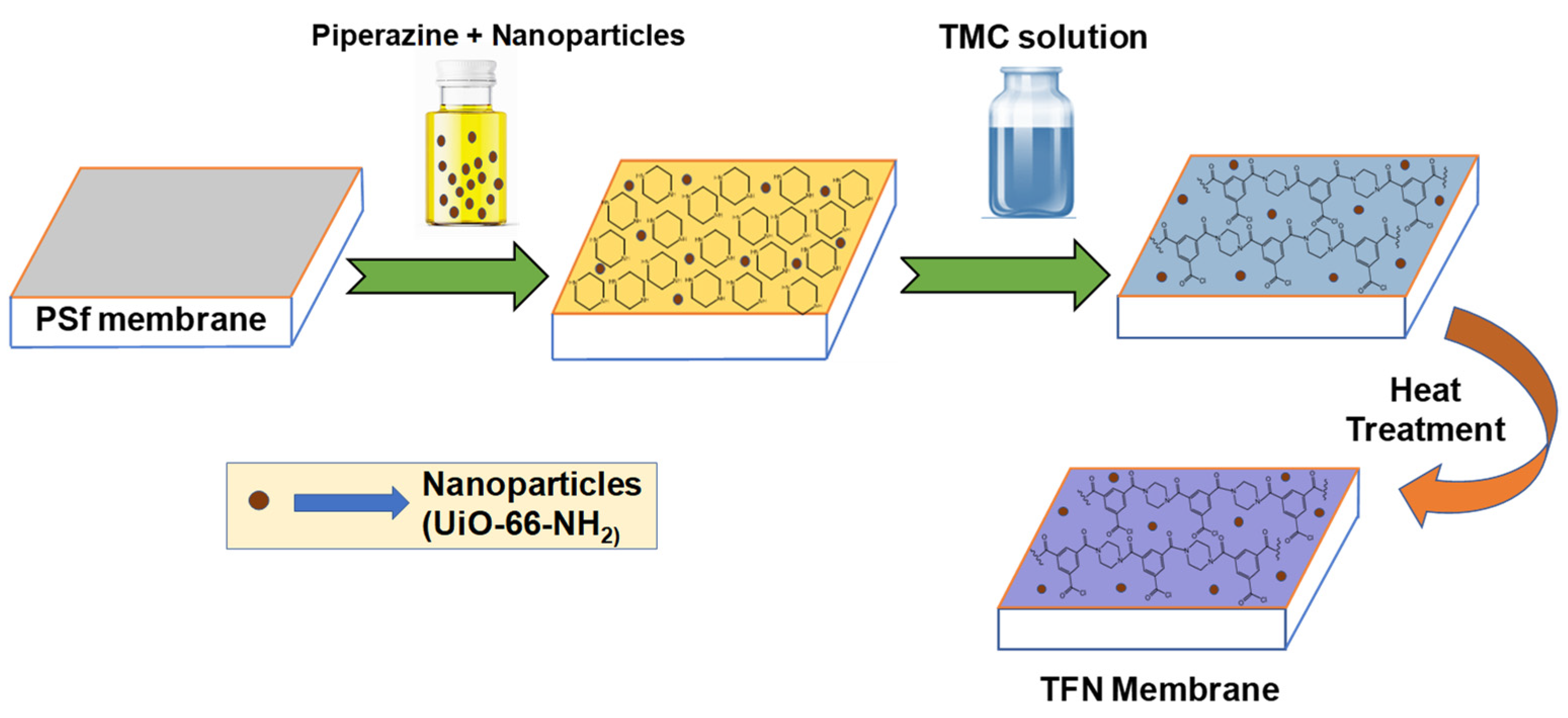
2.4. Preparation of M1 and M2 Membrane

Two different kinds of membranes were prepared by using interfacial polymerization on the polysulfone membrane surface. Simple TFC and TFN membranes were synthesized for the comparative study. For modifying the surface, 2 wt% piperazine (PIP) aqueous solution and 0.2 wt% TMC in n-hexane solution were prepared. For the development of the TFN membrane, UiO-66-NH2 (0.02 wt%) nanoparticles were mixed in the aqueous phase monomer. To prepare the thin selective layer the PSf membranes were first coated with an aqueous phase by immersing in the solution for 10 min. After that, the membranes were drained off for a time to remove the additional water on the membrane surface. The PIP coated membrane was then immersed in the TMC containing n-hexane organic solution where the interfacial polymerization took place for 1 min and a thin film was constructed on the PSf membrane’s surface. The TFC and TFN membranes are then subjected inside the oven for 10 min at 65–70 °C. A schematic representation of preparing the TFN membranes is shown in Figure 1. The TFC and TFN membrane’s preparation and composition are summarized in Table 1.

2.5. Material and Membrane Characterization Techniques

The Attenuated Total Reflectance Fourier Transform Infrared (ATR-FTIR) is an analytical technique that is used to detect organic, inorganic, and polymeric materials. Infrared light is used in this method to scan test samples and observe chemical properties. Using Perkin Elmer, System 2000 Infrared spectrophotometer, Massachusetts, United States America, wave number measured as frequency over the range 4000–400 cm1. Analysis for XPS-using Thermo-Fisher-Scientific: ESCALAB Xi MA, USA, was carried out and is used for measuring the composition, pragmatic formula, and electronic and chemical state of the elements inside the materials. The morphology and internal structure of the composite membranes were examined by FE-SEM. FE-SEM analysis results to show surface anatomy and their cross-section used the instrument Carl ZEISS Microscopy, Germany. For the calculation of phosphate (the molybdenum blue method) and malachite green dye rejection, the absorbance amount was determined by UV-Visible spectrophotometer, Specord 200 of Analytik Jena, Jena, Germany. The contact angle analysis was carried out using KYOWA (Interface Science Co. Ltd. Tokyo, Japan), Model-DM-501, to measure hydrophilic and hydrophobic characteristics of the membrane by determining angle. TGA was performed, and heated the samples to 700 °C, at a heating rate of 10 °C min1, in an N2 atmosphere. TGA data were used to determine the weight of the encapsulated extractant per unit weight of PSf.

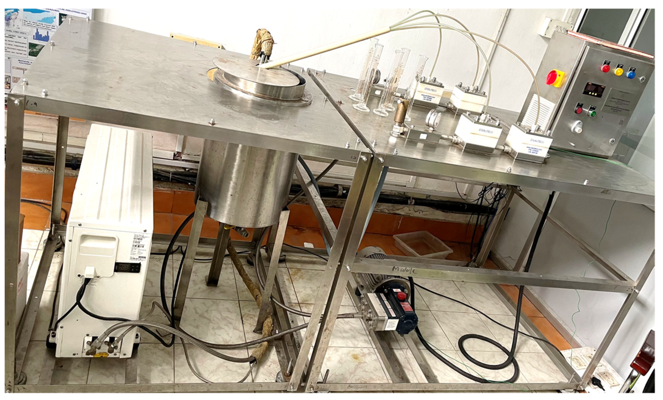
2.6. Permeability and Removal Test

The performance of the synthesized M1 and M2 membranes was tested in the crossflow NF/RO four-cell membrane testing unit provided by M/s. Prova Pvt. Ltd. Mumbai, India, shown in Figure 2. The membranes were subjected to the crossflow cells and first run with deionized water for 2 h to mitigate the experimental errors. Two different feed solutions; a 100-ppm aqueous solution of malachite green dye and a 10-ppm aqueous solution of KH2PO4 (phosphate feed) were prepared. The pH of the KH2PO4 feed solution was decreased to 4 from 7 by adding 0.1 N concentrated HCl dropwise. Membranes are tested for 8–10 h at two different pressure ranges; 10 bar and 15 bar. The permeability was calculated by measuring the permeate volume each hour using Equation (1). UV-spectrophotometer is used for measuring the occurred rejection in the permeate for malachite green and Equation (2) is used for calculating percentage rejection.
Permeation = Volume Area   × time
The unit of the flux is Lm−2h−1.
%   Rejection = A f A p A f × 100
where Af is feed-absorbance and Ap is permeate-absorbance, measured at ~617 nm.
The adsorption study for 10 ppm phosphate solution (by dissolving KH2PO4 in deionized water) has been carried out. The molybdenum blue method [38] is used to measure the adsorption/rejection efficiencies via UV-visible spectrophotometry.

2.7. Antifouling Testing of Membrane

The antifouling capabilities of prepared membranes were examined by testing them against a mixture of 500 ppm BSA + 25 ppm Na2SO4 + 25 ppm CuSO4 aqueous solution (Mix feed) and deionized water (DI) at 10 bar pressure. The permeation of the membranes was first examined every 30 min with DI water for 90 min. The obtained average pure water permeation value was noted as Jw,1. Then the Mix feed was filled in the feed chamber and membranes were tested for 90 min. The permeation value was measured at every 30 min and their average was noted as Jm. After that DI water permeation was measured again which was noted as Jw,2. This was run for 450 min and permeation values were measured. Using Equations (3) and (4), the total fouling percentage (FT) and flux recovery ratio (FRR) were calculated. After 360 min the membranes were washed with deionized water for 1 h to remove the fouling and then the DI water permeation was measured again, the final water flux was noted as Jw,f. The permeation value against Mix feed before washing was considered final mixed feed flux Jm,f. With the help of Equations (5) and (6) the reversible (FR) and irreversible fouling (FIR) that occurred on the membrane during complete testing was calculated.
Total   Fouling   ( F T ) = J w , 1 J m J w , 1 × 100
Fouling   recovery   ratio   ( F RR ) = J w , 2 J w , 1 × 100
Reversible   Fouling   ( F R ) = J w , f J m , f J w , 1 × 100  
Irreversible   Fouling   ( F IR ) = J w , 1 J w , f J w , 1 × 100

2.8. Antibacterial Activity Testing

The antibacterial activity testing of the prepared membranes is carried out by the plate colony-forming count method. Nutrient agar aqueous homogeneous solution was prepared and set into the autoclave to sterilize. Then after the agar solution was poured into the glass petri dish which later becomes solidified, similar to gel. Nutrient agar is the food for the bacteria colony growth. The M1 and M2 membrane pieces were first sterilized by cleaning with 70% ethanol solution and exposing them to UV light. Then they are set on the agar Petri dishes and cultured Gram-positive bacteria S. aureus (Staphylococcus aureus) and Gram-negative bacteria E. coli. (Escherichia coli) was spread on the membrane’s surfaces. At one part of the petri dish aminoglycoside antibiotic named “Neomycin” was dropped a little for reference. The petri dish was then set to overnight incubation at 37 °C with a rotary shaker.

3. Results

3.1. Characterization

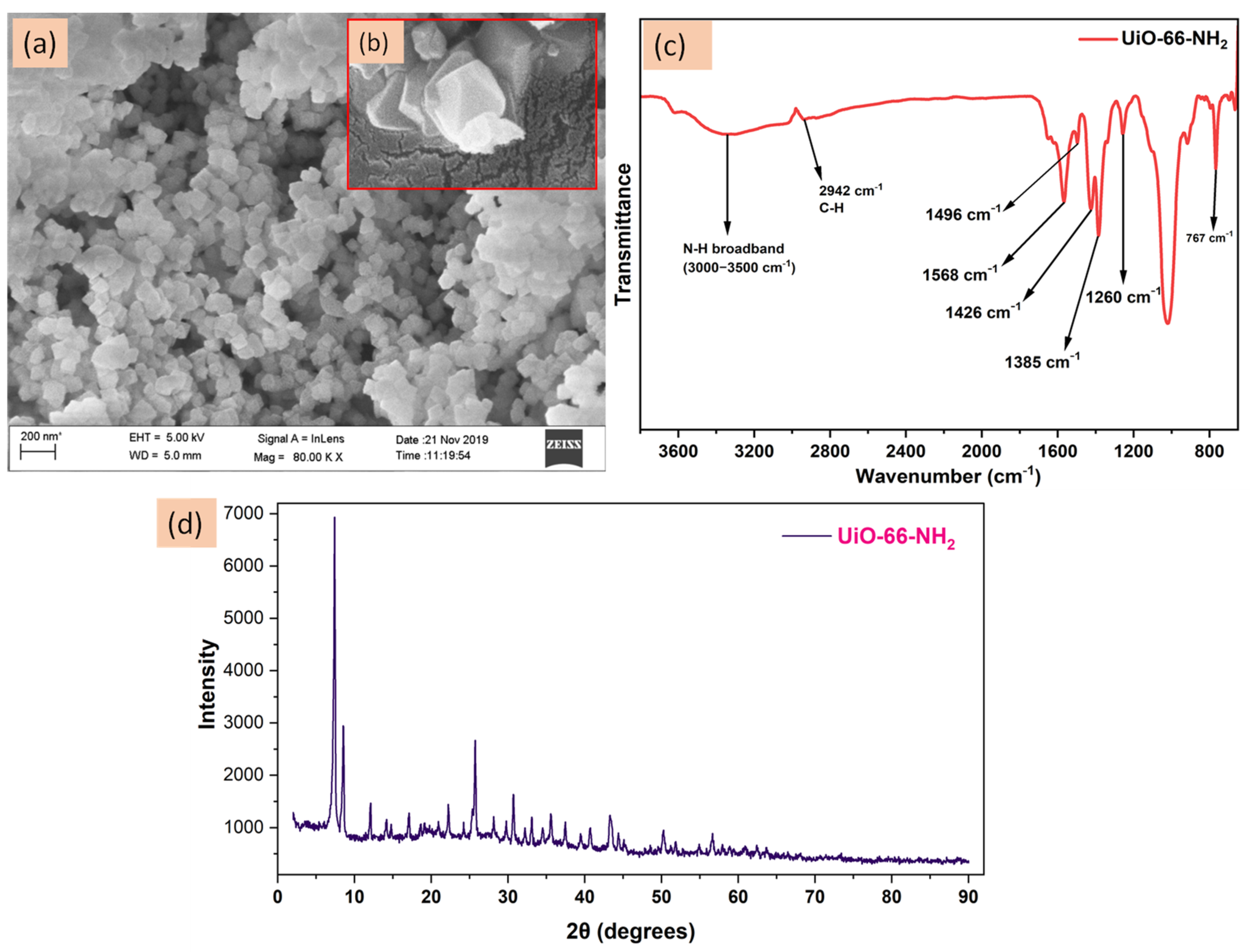
3.1.1. Nanomaterial Characterization

The synthesized nanomaterial UiO-66-NH2 was characterized using the ATR-FTIR and FE-SEM to have an idea about its size, shape and functionality on it. Figure 3a represents the FE-SEM image of the prepared nanomaterials at 80 K magnification.
It is clear from the image that the prepared nanomaterials are very fine and have sizes ~100 nm. The UiO-66-NH2 nanoparticles are octahedral in shape which can be visualized in their FE-SEM image in Figure 3b [39]. Figure 3c is the ATR-FTIR analysis. Different characteristic peaks are obtained which are mostly due to the organic part of the nanomaterial. The Zr-O peak which was obtained around 490 cm−1 was not depicted in the spectrum. Strong broadband from 3000–3500 cm−1 was observed due to the N-H stretching and its bending falls under 1500–1600 cm−1. The peaks around 1260 and 1384 cm−1 can be attributed to C-N stretching between aromatic carbon and the NH2 group. The C-N bending peak at 767 cm−1 is also present which is due to the C-N bending. The characteristic C-H stretching peak is obtained at 2942 cm−1. The COO group present in the nanomaterial due to the added 2-aminoterephthalic acid shows characteristic peaks of asymmetrical stretching at 1496 and 1568 cm−1 while the symmetrical stretching peaks are obtained at 1426 and 1385 cm−1 [40,41]. Figure 3d is the obtained pattern of the powder-XRD analysis of UiO-66-NH2 nanoparticles. The obtained sharp lines in the pattern exhibit their high crystalline nature [42]. The FE-SEM, FTIR and XRD patterns provide the confirmational idea about the nanomaterial. As reported by Aghajanzadeh et al. in their research article UiO-66-NH2 nanomaterial provides a surface area of ~1258 m2/g and a pore volume of ~0.51 cm3/g exhibits that UiO-66-NH2 nanomaterials have a high surface area which is very beneficial for the membrane’s hydrophilic surface modification [43].

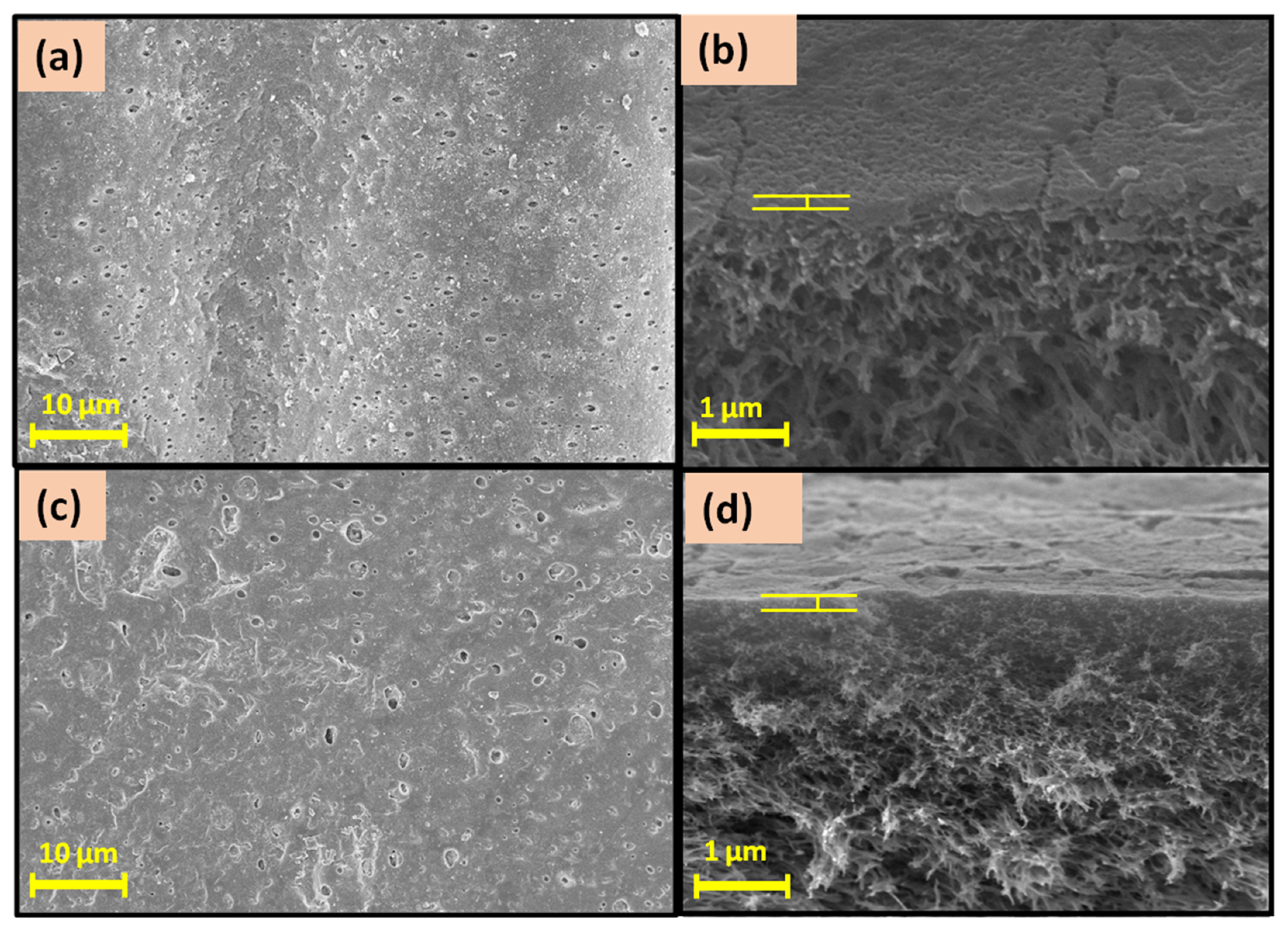
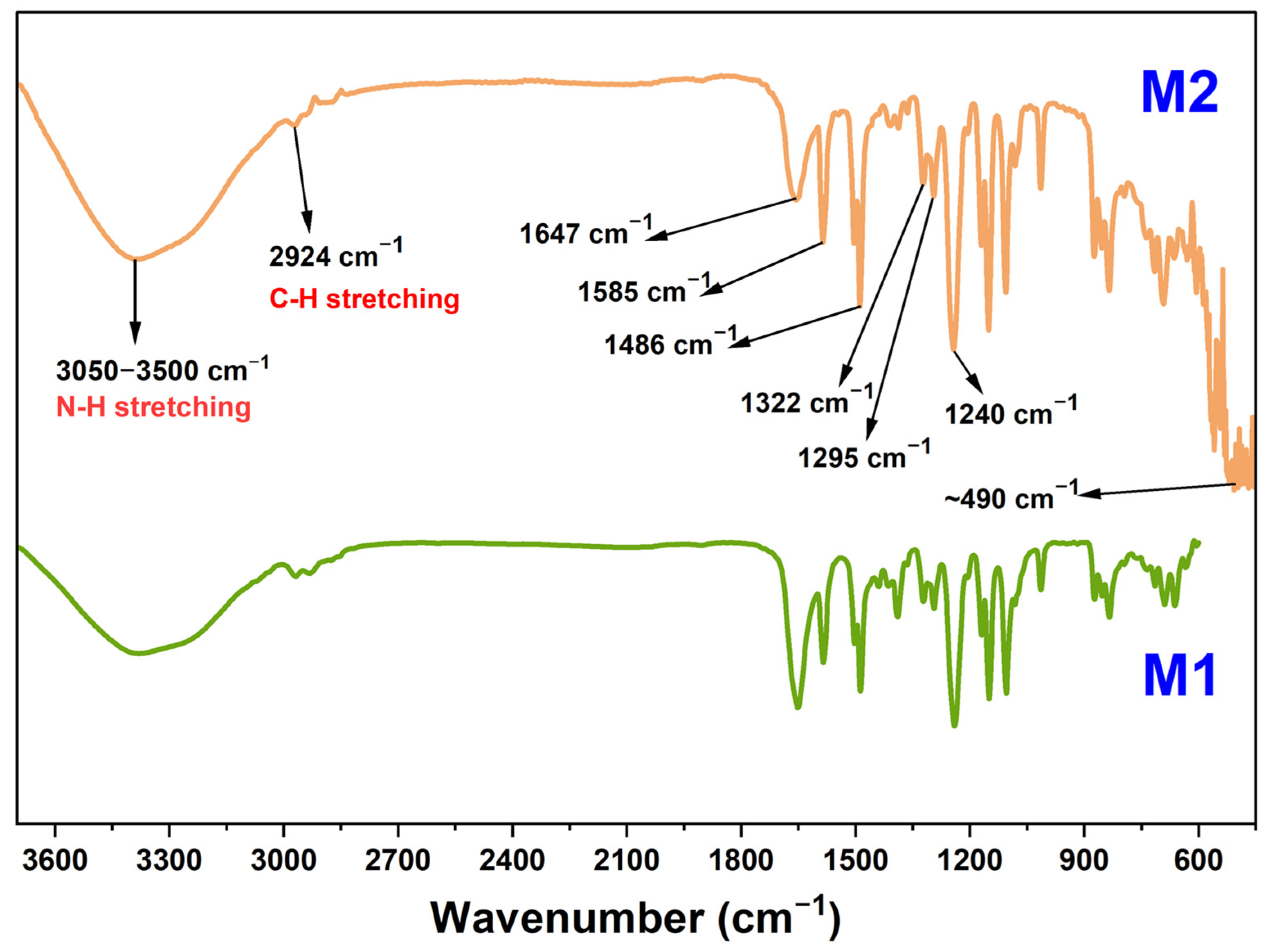
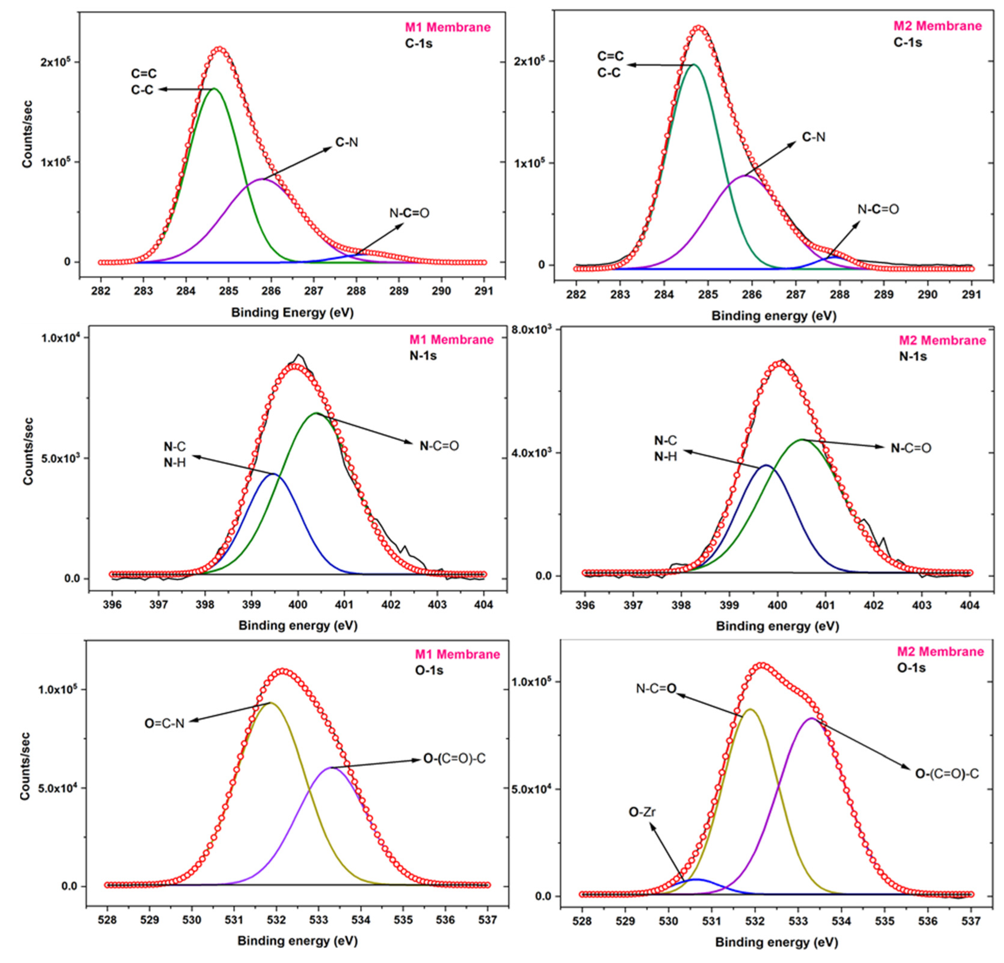
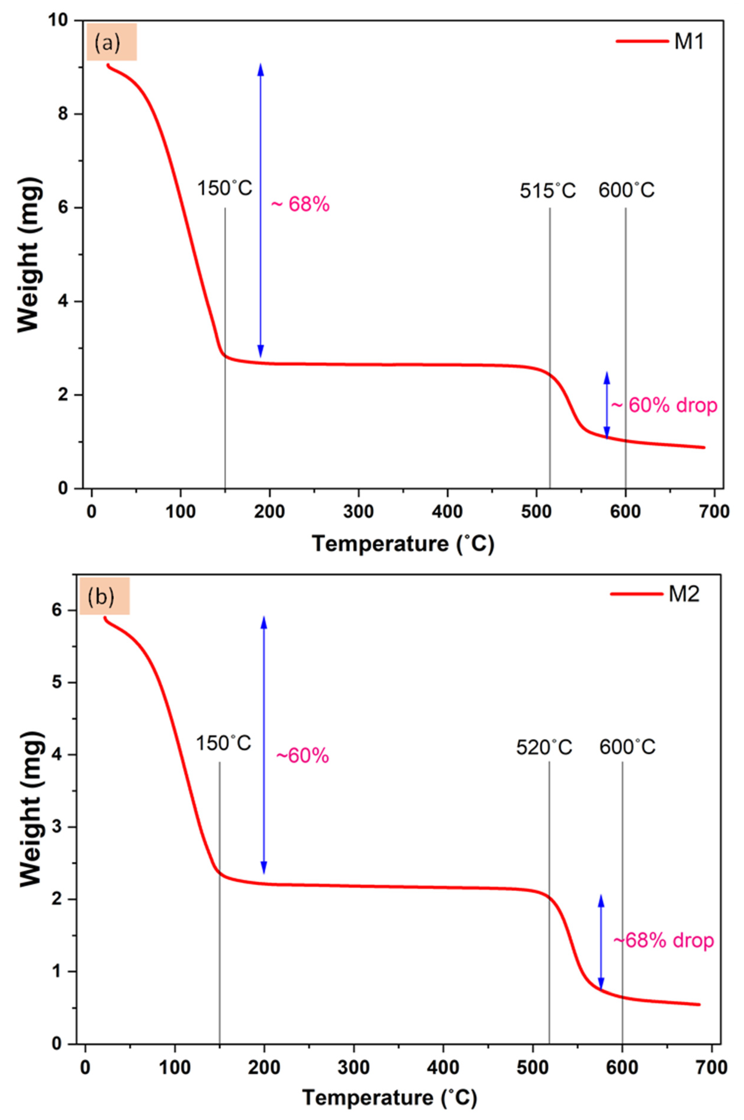
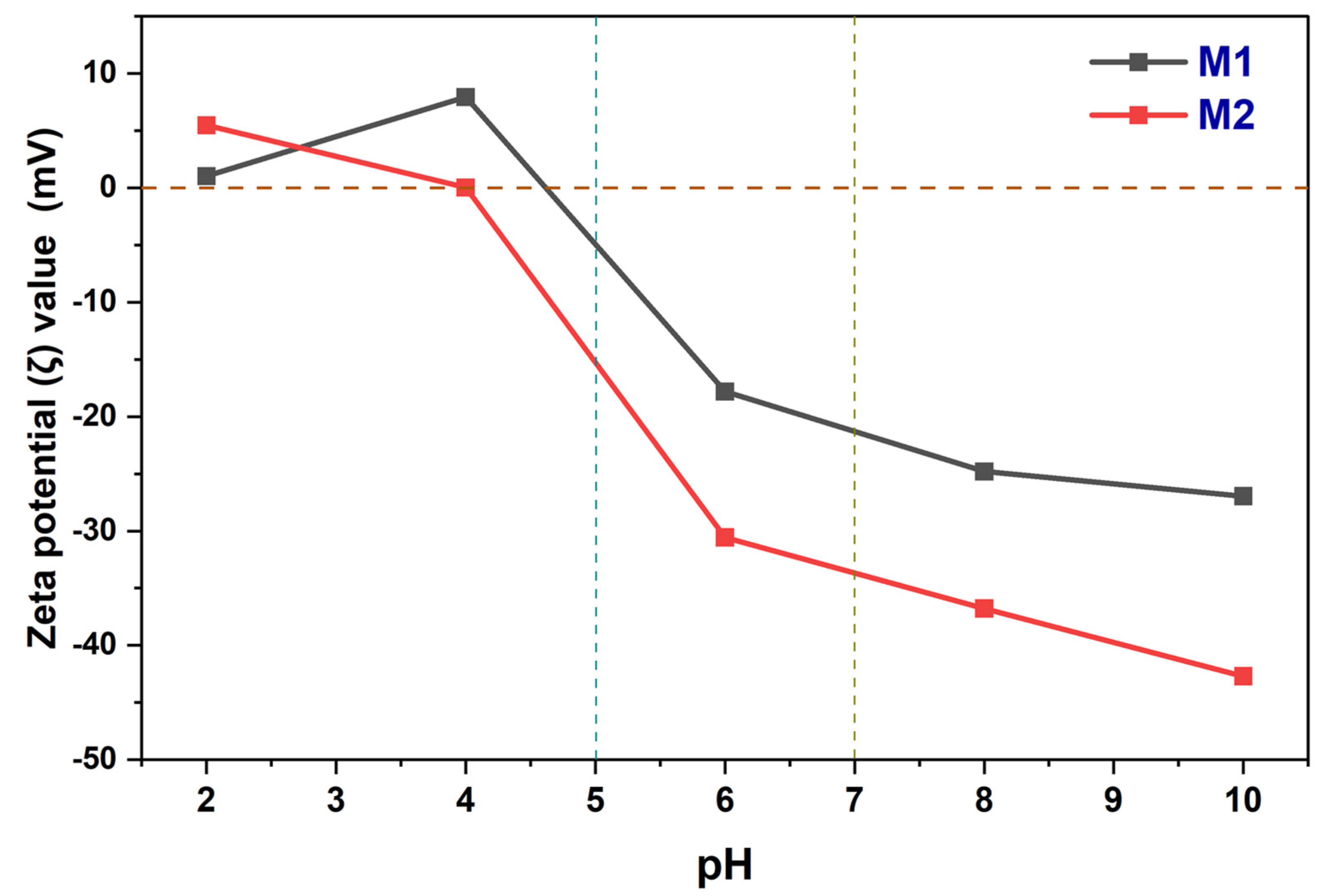
3.1.2. Membrane Characterization

The prepared TFC and TFN membranes were characterized by several spectroscopic and non-spectroscopic techniques to analyze their composition, construction, and surface and have an idea about their performance behaviour. The obtained FE-SEM images of the prepared TFC and TFN membranes are shown in Figure 4. On comparing the TFC (M1) and TFN (M2) membranes FE-SEM images, one can see better structures and more layer formation on the M2 membrane also a greater number of pores have been covered and reduced to a shorter diameter by the layer in M2 membrane. The (b) and (d) images show the cross-section of the prepared M1 and M2 membrane, respectively.
Most of the cross-section image part was covered by the PSf and the porous inside structure is visible through the image. The porous structure allows the water molecules to pass inside the membrane and the surface-active thin-film hydrophilicity determines the water permeation behaviour. The more hydrophilic surface layer will have higher permeation which was measured by the water contact angle with the surface. By using the sessile drop method, the water contact angle of the prepared membrane’s surface was analysed. Table 2 represents the contact angle values and corresponding images of the prepared membrane. For comparing and understanding the effect of thin-film formation and nanomaterial incorporation the contact angle of the pristine PSf membrane was also measured. The polyamide layer was constructed on the PSf membrane surface in the M1 membrane which imparts polarity due to the amide group present on it and enhances the interaction with the water. It can also be seen with the dropped contact angle value of the TFC membrane compared to PSf membrane. The nanomaterials are functionalized with -NH2 groups which are known for creating hydrogen bonding with the water molecules thus their addition further enhances the surface hydrophilicity. As seen for the M2 membrane the water contact angle has dropped lower than the M1 membrane showing the effect of incorporated nanomaterials. The nanomaterials have also consisted of aromatic rings which are water repellent due to their hydrophobic behaviour and the concentration of nanomaterial was very small due to which a greater drop in the contact angle was not observed [44].
The greater hydrophilicity on the surface is determined by the polar groups on the surface of the prepared membrane. Functional groups and other polar bonds with a certain dipole moment vibrates when subjected to IR light with different frequency. FTIR analysis technique is utilized to read and understand these vibrational motions and depict the type of bond. Figure 5 represents the ATR-FTIR spectra of the prepared M1 and M2 membranes. Most of the peaks obtained for the M1 and M2 membranes are common as both have a thin film layer made of polyamide and the same polysulfone support. Nanomaterials are the added extra materials in the M2 membranes and the characteristic peak of Zr-O due to those UiO-66-NH2 particles is visible ~490 cm−1 in the M2 membrane [45]. The carbonyl peaks at 1647 cm−1 and the broadband of N-H stretching at 3050–3500 cm−1 confirms the presence of the thin polyamide film on both the membranes. The peaks at 1486 cm−1 and 1585 cm−1 occurred due to the aromatic C-C stretching which is present in the thin film as well as in the nanomaterials and polysulfone support. The strong peak at 1240 cm−1 is attributed to the C-O-C bond and the peaks at 1295 cm−1, and 1322 cm−1 are denoted by asymmetric stretching of the O=S=O group. The peak around 2924 cm−1 is the significant peak of C-H stretching [46].
X-ray photoelectron spectroscopy (XPS) analytical tool is used for elemental compositions. It also gives insight into the types of bonds on the surface. The prepared membranes are examined by XPS. The different high-resolution XPS graphs of carbon, nitrogen and oxygen elements are deconvoluted for the M1 and M2 membrane and represented in Figure 6. Different peaks of an element arise due to different surroundings present in the thin film. In the C-1s deconvoluted graph three major peaks around ~284.6 eV, ~285.9 eV and ~287.8 eV are fitted for carbons of C=C/C-C, C-N and N-C=O of amide, respectively. The polyamide thin-film possesses the nitrogen element and peaks due to the nitrogen of N-C/N-H and N-C=O bonds are shown at ~399.6 eV and ~400.4 eV for both the membranes [47].
Both the membranes differ in the nanomaterials which contain the Zr-O bonds characteristic of the UiO-66-NH2 nanoparticles. While assigning the peaks on the O-1s deconvoluted XPS spectrum an extra peak for the O-1s of the O-Zr bond has been represented in the M2 membrane [48]. The peak of O-1s of the O-Zr bond is at ~530.5 eV with low intensity as the nanoparticle’s concentration is small. Other O-1s peaks due to O=C-N and O-(C=O)-C are denoted at ~531.9 eV and ~533.6 eV. The represented O=C-N bond formed during the interfacial polymerization while the left acyl chloride group which has found a water molecule before the amine monomer has a reaction and hydrolysed and formed acid group shown by O-(C=O)-C. The UiO-66-NH2 contains many oxygens associated with the O-(C=O)-C group as well which also contributes in the case of the M2 membrane.
The thermal stability of the prepared membranes was also tested up to 700 °C. The TGA analysis report of the prepared membranes is shown in Figure 7. Both the M1 and M2 membranes have shown an initial weight loss of 150 °C which is mostly due to the volatile matter and water moisture. Almost 60–68% of the weight was removed until 150 °C which may be due to the polymeric membranes may have gotten wet during the testing. After that, both the membranes are well stable up to 515–520 °C. The decomposition of the polymeric material and organic molecules begins after it and up to 600 °C, the M1 membrane showed a ~60% weight drop (from 515 °C to 600 °C) and the M2 membrane showed a ~68% weight drop (from 520 °C to 600 °C). The M2 membrane has a greater drop compared to the M1 membrane which is due to the added nanomaterials. The UiO-66-NH2 nanoparticles also have the organic aromatic part which also decomposes between 500–600 °C, because of this there is observed a higher % drop in the weight of the M2 membrane [49].
The observed graphs have displayed the thermal report of the prepared membranes as shown in Figure 7, however not a significant difference has been observed between M1 and M2 membranes. One can predict the M2 membrane is more thermally stable as it decomposes at 520 °C which is 5 °C greater than the M1 but such a small difference is not very significant. Most of the parts of the M1 and M2 membranes are the same and the added nanomaterials are very less in numbers as well.
In the case of nanofiltration membranes, while performing ion separation, the surface charge value of the membranes affects their performance as the Donnan ion effect comes into prominent action. The surface charge value was measured with the help of zeta potential (ζ) and the prepared membranes M1 and M2 were analysed for it. The obtained graph from the zeta potential values of the membranes is shown in Figure 8. The figure depicts both the membranes having isoelectric points between pH 4 and pH 5. Above this point, the membranes are exhibiting a negative zeta potential value showing their anionic behaviour. The M2 membrane showed a higher negative zeta potential (ζ) value which can be considered due to the added nanomaterial (UiO-66-NH2). The polyamide layer built on the surface of both the membranes exhibits anionic behaviour due to the amide functional group, on the above, the added UiO-66-NH2 nanomaterial is rich in oxygen content which provides extra negative charge to the M2 membrane over M1. A higher charged surface gives rise to a stronger Donnan ion effect on the membrane. Considering the older membranes prepared using UiO-66-NH2 and COOH-TiO2, the currently prepared membranes showed excellent negative charge potential [1,50].

4. Discussion

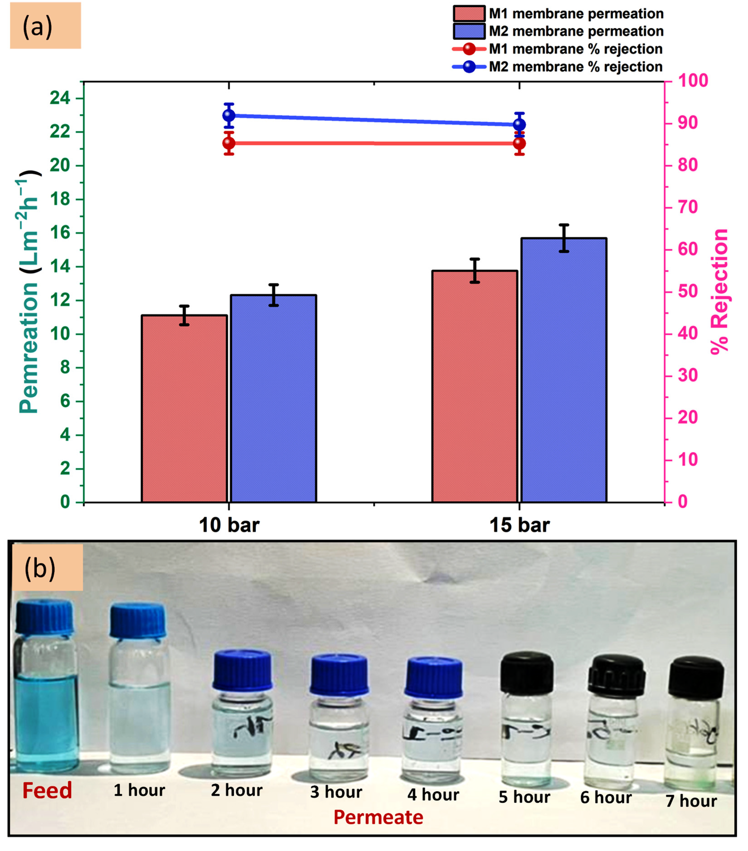
4.1. Removal of Malachite Green Dye by TFC and TFN Membranes

The prepared TFC and TFN membrane’s performance in removing 100 ppm malachite green is evaluated by testing in four cell membrane testing units. The obtained results are represented by a graph in Figure 9a and images are shown in Figure 9b. The membranes are tested at two different pressure 10 and 15 bar to understand the effect of pressure on the membrane performance. At 10 bar pressure the membranes M1 and M2 have shown 11.11 ± 0.5 and 13.32 ± 0.6 Lm−2h−1 permeability, respectively. The M2 membrane has higher permeability which is due to its more hydrophilic surface as explained by the contact angle experiment. The percentage rejection of malachite green by the M2 membrane is 91.90 ± 3%, which is higher than the M1 membrane having 85.34 ± 3% rejection. The M2 membrane differs from the M1 membrane only by the added nanomaterials and thus the difference in the percentage rejection value can be attributed to them. However, the difference is not large, yet it has increased the rejection by >90%. For a dye similar to malachite green which is a big size molecule, the separation mainly occurs by the size exclusion phenomenon. In addition, we have seen in the FE-SEM images the pore sizes of the M2 membranes are covered and reduced to smaller sizes due to the added nanomaterials. The nanomaterials are added to enhance the performance of the membranes and the obtained results are proving their effect even at higher pressure. When the pressure was raised to 15 bar the permeance increased as expected, but the percentage rejection decreased by a small margin. This is caused by the increased pressure which increases the pore size of the membrane that allows more permeation of the feed solution yet the rejection ability which is dependent on size exclusion and Donnan ion effect decreases. The results at 15 bar exhibit 13.77 ± 0.7 and 15.70 ± 0.8 Lm−2h−1 permeability from M1 and M2 membrane, respectively with corresponding 85.30 ± 3% and 89.74 ± 3% dye rejection. We observed negligible decrement in the percentage rejection of the M1 membrane when pressure increased to 15 bar but ~2% decrement occurred for the M2 membrane and the permeability of both the membranes have increased ~23–28%.
As for the high molecular weight dyes and proteins, size exclusion-based separation remains prominent. This is an assuring point for the prepared membranes that they can better remove the higher molecular weight dyes than malachite green. For example, Li et al. reported the preparation of UiO-66-NH2/GO composite nanofiltration thin-film membrane, which they used for removing cationic methylene blue (MB), neutral rhodamine B (RB) and anionic Congo red (CR) dyes [51].

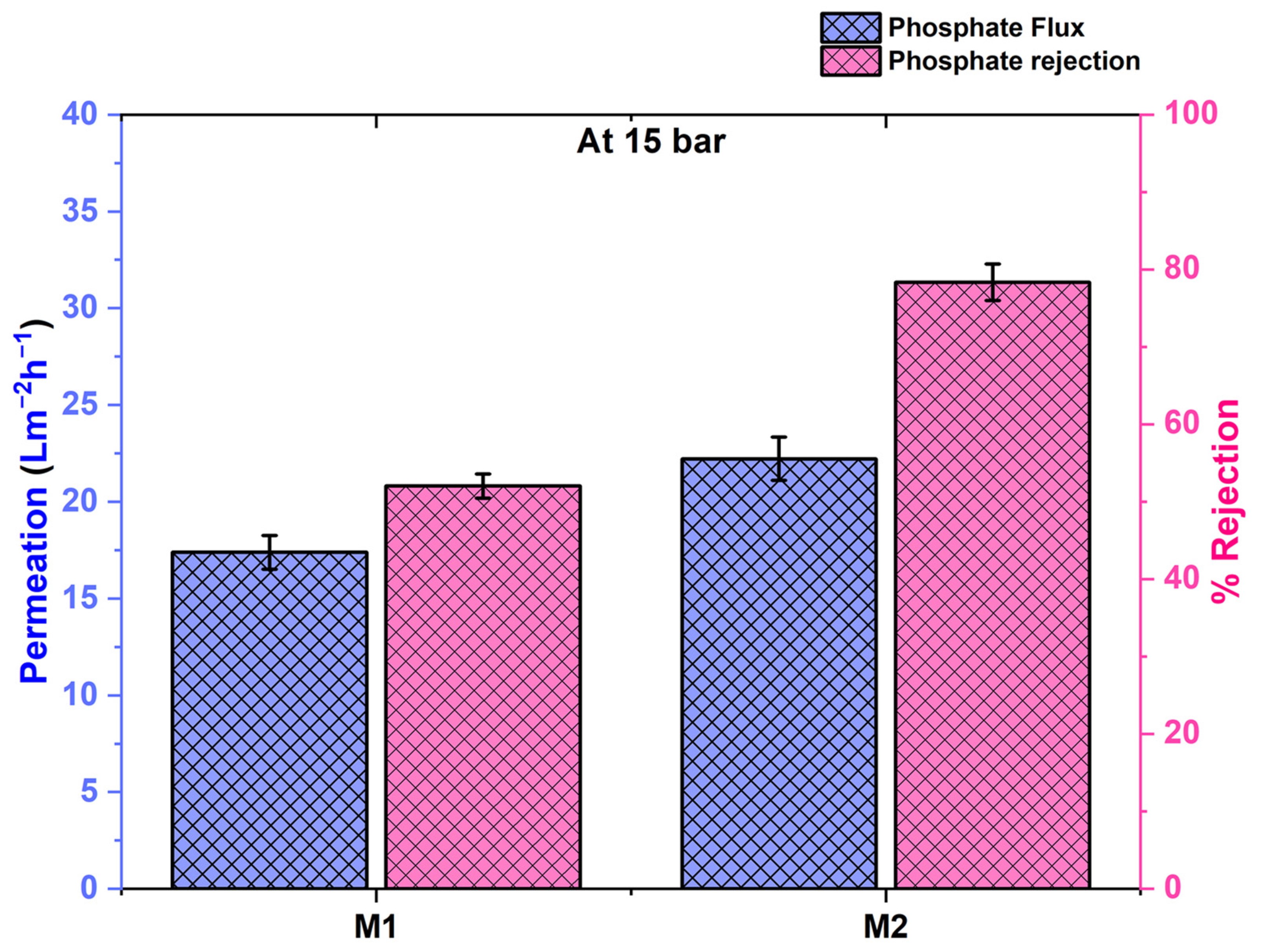
4.2. Removal of Phosphate by TFC and TFN Membranes

The phosphate removal ability of the membrane has also been tested at 15 bar pressure. The plotted graphs for the M1 and M2 membrane’s permeation and rejection have been represented in Figure 10 with cross-pattern bar diagrams. The M1 membrane has shown 17.39 ± 0.9 Lm−2h−1 permeability with 52.05 ± 3% rejection of the phosphate ions. Meanwhile, the nanomaterial-loaded M2 membrane showed 22.22 ± 1.1 Lm−2h−1 permeability with 78.36 ± 3% rejection. The permeability of the M2 membrane is greater than the M1 due to the greater surface hydrophilicity and it also exhibits the greater rejection of phosphate ions. The difference between the percentage rejection is significantly bigger as the M2 membrane has exhibited ~26% greater separation. The Donnan ion effect works effectively against ions and the added nanomaterials contain oxygens that make the membrane surface more negative which was already been negative due to the polyamide layer at neutral pH. Adding the UiO-66-NH2 nanoparticles which have metal oxide bonds (Zr-O) and are polar in nature have enhanced the Donnan phenomenon. Due to this, the M2 membrane’s surface is more negatively charged as seen in the zeta potential graph in Figure 8 and the rejection of phosphate ions has occurred more.
The obtained results of phosphate removal seem weak if we look at the rejection of the dyes carried out by the same membranes. One thing also to be noticed here is that the feed concentration was only 10 ppm while phosphate separation, which is very small compared to the 100 ppm feed solution while separating the dye. Removing the impurity from a less concentrated solution is always harder and also the different phenomenon (Donnan ion effect) is prominent for phosphate separation.

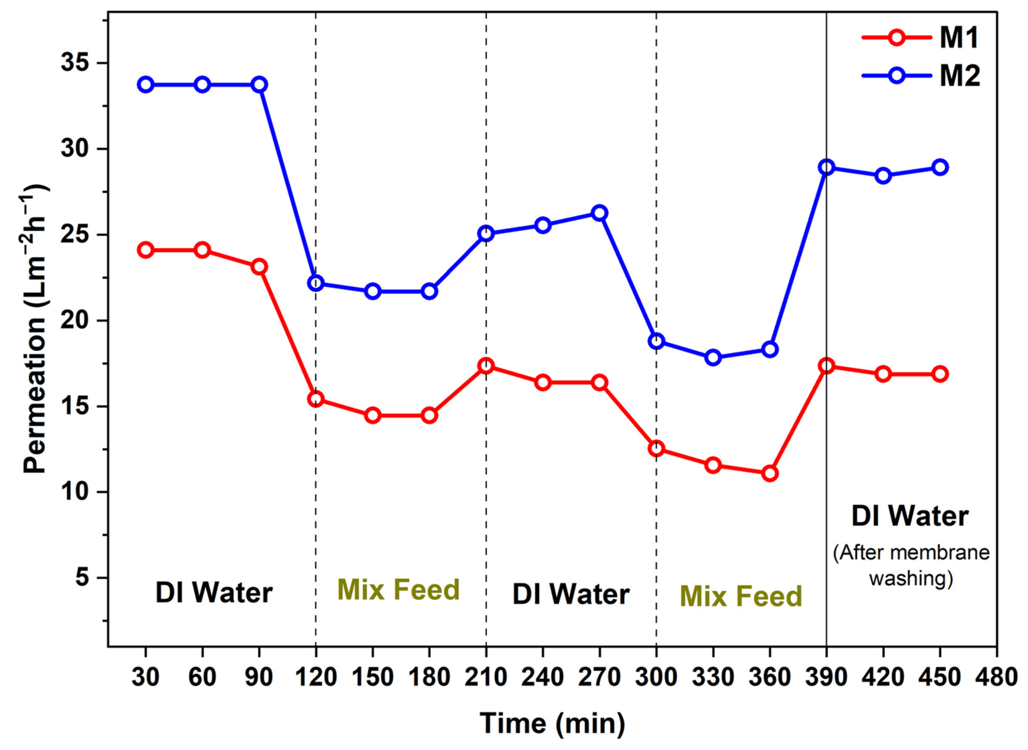
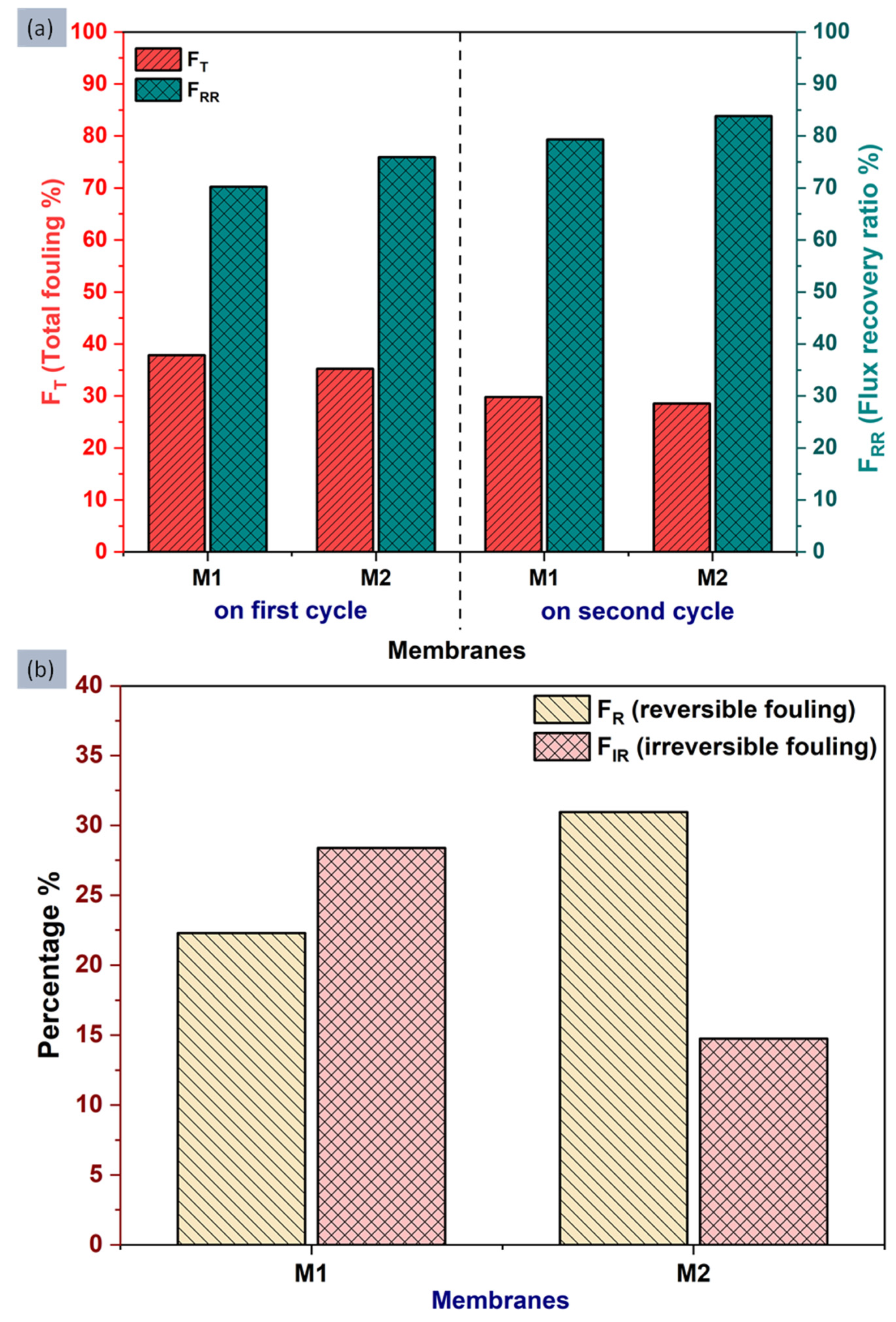
4.3. Antifouling Study of the Membranes

Antifouling studies have been carried out to test the tendency of membrane surfaces to stay clean from fouling. Organic proteins are mostly the molecules that cause the fouling therefore for the testing BSA protein is used along with Na+ and Cu2+ ions. The variation in the permeation value with time has been represented in Figure 11. As can be seen in Figure 11 the permeation value decreased against mix feed and again increases when conducted with deionized water (DI). Membranes are alternatively treated with deionized water and mixed feed solution to check the total fouling (FT) and flux recovery ratio (FRR) that occurred in a particular cycle.
Figure 12a shows the bar graph of total fouling (FT) and flux recovery ratio (FRR) observed for the M1 and M2 membranes in two consecutive cycles. FT is the measurement of the total fouling that occurred in the membranes and FRR is the measurement of total recovered water flux after fouling, it is also referred to as the “antifouling tendency” of the membrane. During the first cycle, the TFC M1 membrane exhibited 37.8% total fouling with 70.2% flux recovery, while the TFN M2 membrane showed a smaller FT value of 35.2% only, and a greater FRR value of 75.9%. In the second cycle, the FT value has been decreased by 7–9% and the FRR value increased by 6–10% for both M1 and M2 membranes still the M2 membrane has a low total fouling percentage (FT) of 28.5% and a high flux recovery ratio or antifouling tendency (FRR) 83.8%. The decrement in the total fouling and flux recovery ratio can be attributed to the added nanomaterials. Even the contact angle values have demonstrated that the M2 membrane has a greater hydrophilic nature which also confirms the point that more hydrophilic membranes are less prone to organic fouling [1].
The total fouling of the membrane can be considered of two types one is reversible fouling (FR) and another is irreversible fouling (FIR). Reversible fouling (FR) was easily washed away with normal water cleaning and for that, the membranes were dipped into the water after 360 min, for 1 h to remove the fouling. FR and FIR are the measurements which represent reversible fouling and irreversible fouling, respectively. The obtained and calculated percentage amount of FR and FIR has been represented in Figure 12b. It has been found that the M2 membrane exhibited a higher 30.9% reversible fouling (FR) than the M1 membrane with a 22.2% FR value. However, the percentage of irreversible fouling (FIR) for the M2 membrane is 14.7%, which is less compared to the M1 membrane showed an FIR value of 28.3%, which is twice the M2.
The obtained values of the FT, FRR, FR and FIR conclude that compare to the TFC M1 membrane, the TFN M2 membrane surface exhibits less amount of total fouling (FT) and a higher fraction of it is reversible, also the TFN M2 membrane has a better antifouling tendency as well. The smaller value of FIR for the TFN M2 membrane represents the tendency of its surface to stick weakly with fouling materials [52,53].

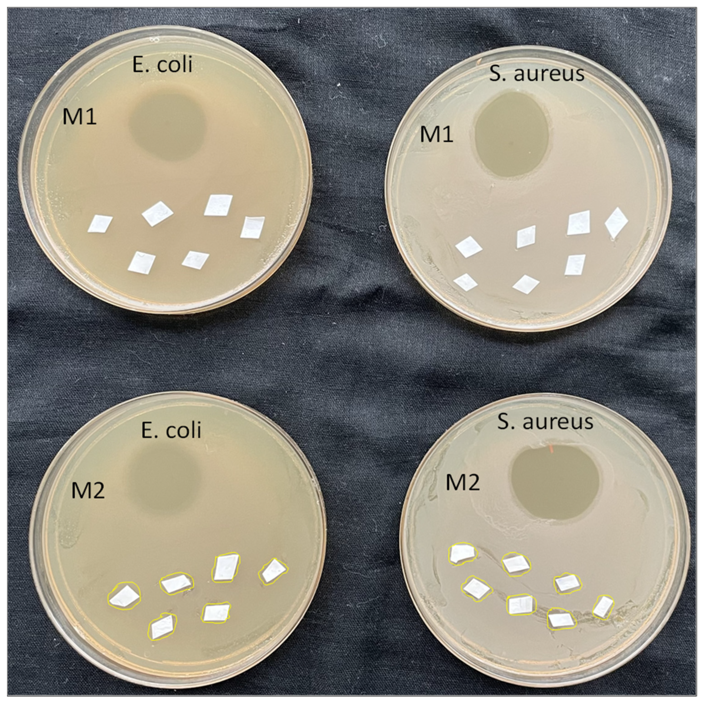
4.4. Antibacterial Activity of Prepared TFC and TFN Membranes

The antibacterial study of the prepared TFC and TFN membranes was carried out by the bacterial colony growth method against Gram-negative E. coli. (Escherichia coli) and Gram-positive S. aureus (Staphylococcus aureus) bacteria to check whether the membrane has antibacterial activity or not. From our previous work, the involvement of mesoporous synthetic hectorite (MSH) mixed UiO-66-NH2 nanoparticles has shown good antibacterial activity. In the current experiment, Figure 13 displays the antibacterial results of prepared membranes after subjecting with bacteria for 24 h. The aminoglycoside antibiotic named “Neomycin” was also used as a positive control to show activity against bacteria and used as the reference standard. The antibiotic exhibited a superior circular inhibition zone which is visible in Figure 13. The white sheets are the pieces of the membranes spread over the agar. A close look at the images of the M1 and M2 membrane in Figure 13 depicts that there is some retardation while colony-forming which is visible around the M2 membrane. Whereas, the M1 membrane has no mitigation against both the bacteria. The M2 membranes have shown mild antibacterial activity. It can be expected that the M2 membrane has interrupted the cells of the bacteria and due to the metal oxides present on the nanomaterials, the oxidative stress has further enhanced the antibacterial activity. The M2 membrane’s results have shown that the incorporated nanomaterial has developed antibacterial properties on the membrane [54]. The M2 membrane retarded S. aureus in its surrounding area, which is marked with yellow lines, showing the membrane’s inhibition zone. However, weak retardation of E. coli. was observed by the M2 membrane. The nanomaterial was loaded in a very small amount in the TFN M2 membrane, so it can be expected that the higher loading of nanomaterial may lead to better antibacterial activity.

5. Conclusions

Thin-film composite (M1 membrane) and Thin-film nanocomposite (M2 membrane) membranes come under the category of nanofiltration which is the pressure-driven membrane that does effective separation of dyes and ions by size exclusion and the Donnan ion phenomenon. In this experiment, we tested our prepared TFC and TFN membranes against very low concentrated malachite green dye and phosphate ions at higher pressure. The high pressure and low concentrated feed solution is the situation where membranes are triggered to their limit. From testing, we have obtained good results of dye separation from only a 100 ppm solution. The phosphate removal was measured from a very less concentrated 10 ppm solution which is harder to remove, and we obtained ~78% rejection with 22.22 Lm−2h−1 permeability from TFN membrane (M2 membrane). Compared to the dye separation the difference between the M1 and M2 membrane’s separation ability is greater while rejecting phosphate ions. The reasons can be the different phenomena that were more prominent during the separations; size exclusion while dye removal and Donnan effect during phosphate removal. The M1 (TFC) membrane has already been exhibiting good separation of dye which also does not leave a big room for enhancement in rejection with nanomaterial addition.
The permeability of the membrane varies with the type of feed because the feed solutions properties such as density, viscosity, dielectric point, polarity etc. create a difference and as a result, we observed different permeability with different feed solutions. A solution with low viscosity will have greater permeation. The more hydrophilic surface also represents higher permeation as cleared from the contact angle values and the obtained permeation data. A more hydrophilic surface also provides a good antifouling tendency as seen in the antifouling experiment where the M2 membrane showed an enhanced 83.8% FRR and 14.7% FIR value. The antibacterial testing revealed that the nanomaterial addition caused the antibacterial activity in thin film nanocomposite (TFN) M2 membrane and which can further be increased if we increase nanomaterials concentration.

Author Contributions

Data curation, M.B.G. and S.K.; Formal analysis, M.B.G., S.K., D.Y., A.Y. and N.R.T.; Writing - original draft author, M.B.G. and S.K.; Writing - review & editing author, P.G.I.; Methodology, M.B.G., S.K., N.R.T. and P.G.I.; Resources, A.Y., S.H., P.G.I. and H.K.L. Funding acquisition, Investigation, Project administration, Supervision and Visualization, P.G.I. All authors have read and agreed to the published version of the manuscript.

Funding

We are grateful for the support from CSIR, New Delhi India and the DST, New Delhi, India through the grant under the in-house project OLP-2064 and DST/NM/NT/2018/143, respectively. DY and SK are thankful to DST, New Delhi, India for granting DST/INSPIRE fellowship award No. IF-190678 and IF-190333, respectively. NRT is glad to DST, India for funding under the DST/WOS-B/HN-27/2021 project.

Institutional Review Board Statement

Not applicable.

Informed Consent Statement

Not applicable.

Data Availability Statement

Data will be made available on request.

Acknowledgments

Our special thanks to the Director, CSIR-NEIST, Jorhat for his keen interest and continuous support for this work. The authors acknowledged CSIR, New Delhi India and the DST, New Delhi, India for financial support under the project OLP-2064 and DST/NM/NT/2018/143, respectively. DY and SK acknowledged DST, New Delhi, India for DST/INSPIRE fellowship award No. IF-190678 and IF-190333, respectively. NRT acknowledged DST, India for funding under the DST/WOS-B/HN-27/2021 project.

Conflicts of Interest

The authors declare no conflict of interest.

References

  1. Karki, S.; Ingole, P.G. Development of polymer-based new high performance thin-film nanocomposite nanofiltration membranes by vapor phase interfacial polymerization for the removal of heavy metal ions. Chem. Eng. J. 2022, 446, 137303. [Google Scholar] [CrossRef]
  2. Roth, C.D.; Poh, S.C.; Vuong, D.X. Customization and Multistage Nanofiltration Applications for Potable Water, Treatment, and Reuse. Nanotechnol. Appl. Clean Water 2014, 201–207. [Google Scholar]
  3. Guo, H.; Li, X.; Yang, W.; Yao, Z.; Mei, Y.L.; Peng, E.; Yang, Z.; Shao, S.; Tang, C.Y. Nanofiltration for drinking water treatment: A review. Front. Chem. Sci. Eng. 2022, 16, 681–698. [Google Scholar] [CrossRef] [PubMed]
  4. Choi, O.; Ingole, P.G.; Park, C.H. Precision-aiming tuning of membranes prepared by NIPS and its performance enhancement. J. Clean. Prod. 2022, 365, 132858. [Google Scholar] [CrossRef]
  5. Ingole, P.G.; Choi, W.; Kim, K.H.; Jo, H.D.; Choi, W.K.; Park, J.S.; Lee, H.K. Preparation, characterization and performance evaluations of thin film composite hollow fiber membrane for energy generation. Desalination 2014, 345, 136–145. [Google Scholar] [CrossRef]
  6. Ingole, P.G.; Choi, W.; Kim, K.H.; Park, C.H.; Choi, W.K.; Lee, H.K. Synthesis, characterization and surface modification of PES hollow fiber membrane support with polydopamine and thin film composite for energy generation. Chem. Eng. J. 2014, 243, 137–146. [Google Scholar] [CrossRef]
  7. Yadav, D.; Hazarika, S.; Ingole, P.G. Recent development in nanofiltration (NF) membranes and their diversified applications. Emergent Mater. 2021, 1–18. [Google Scholar] [CrossRef]
  8. Singh, K.; Devi, S.; Bajaj, H.C.; Ingole, P.G.; Choudhari, J.; Bhrambhatt, H. Optical resolution of racemic mixtures of amino acids through nanofiltration membrane process. Sep. Sci. Technol. 2014, 49, 2630–2641. [Google Scholar] [CrossRef]
  9. Yadav, D.; Karki, S.; Ingole, P.G. Nanofiltration (NF) Membrane Processing in the Food Industry. Food Eng. Rev. 2022. [Google Scholar] [CrossRef]
  10. Yadav, D.; Karki, S.; Ingole, P.G. Current advances and opportunities in the development of nanofiltration (NF) membranes in the area of wastewater treatment, water desalination, biotechnological and pharmaceutical applications. J. Environ. Chem. Eng. 2022, 10, 108109. [Google Scholar] [CrossRef]
  11. Li, W.; Wang, X.; He, M.; Zhang, Z.; Chen, J.; Yang, G. Fabrication of high-performance nanofiltration membranes by using sulfated cellulose nanofibril as the intermediate support layer. Desalination 2022, 532, 115741. [Google Scholar] [CrossRef]
  12. Mousavi, S.R.; Asghari, M.; Mahmoodi, N.M. Chitosan-wrapped multiwalled carbon nanotube as filler within PEBA thin film nanocomposite (TFN) membrane to improve dye removal. Carbohydr. Polym. 2020, 237, 116128. [Google Scholar] [CrossRef] [PubMed]
  13. Hebbar, R.S.; Isloor, A.M.; Inamuddin; Abdullah, M.S.; Ismail, A.F.; Asiri, A.M. Fabrication of polyetherimide nanocomposite membrane with amine functionalised halloysite nanotubes for effective removal of cationic dye effluents. J. Taiwan Inst. Chem. Eng. 2018, 93, 42–53. [Google Scholar] [CrossRef]
  14. Raval, N.P.; Shah, P.U.; Shah, N.K. Malachite green “a cationic dye” and its removal from aqueous solution by adsorption. Appl. Water Sci. 2017, 7, 3407–3445. [Google Scholar] [CrossRef] [Green Version]
  15. Sartape, A.S.; Mandhare, A.M.; Jadhav, V.V.; Raut, P.D.; Anuse, M.A.; Kolekar, S.S. Removal of malachite green dye from aqueous solution with adsorption technique using Limonia acidissima (wood apple) shell as low-cost adsorbent. Arab. J. Chem 2017, 10 (Suppl. 2), S3229–S3238. [Google Scholar] [CrossRef] [Green Version]
  16. Firouzjaei, M.D.; Afkhami, F.A.; Esfahani, M.R.; Turner, C.H.; Nejati, S. Experimental and Molecular Dynamics Study on Dye Removal from Water by a Graphene Oxide-Copper-Metal Organic Framework Nanocomposite. J. Water Process Eng. 2020, 34, 101180. [Google Scholar] [CrossRef]
  17. Parkerson, Z.J.; Le, T.; Das, P.; Mahmoodi, S.N.; Esfahani, M.R. Cu-MOF-Polydopamine-Incorporated Functionalized Nanofiltration Membranes for Water Treatment: Effect of Surficial Adhesive Modification Techniques. ACS ES T Water 2021, 1, 430–439. [Google Scholar] [CrossRef]
  18. Zhang, J.; Ge, Y.; Li, Z.; Wang, Y. Facile fabrication of a low-cost and environmentally friendly inorganic-organic composite membrane for aquatic dye removal. J. Environ. Manag. 2020, 256, 109969. [Google Scholar] [CrossRef]
  19. Zinadini, S.; Zinatizadeh, A.; Rahimi, M.; Vatanpour, V.; Zangeneh, H.; Beygzadeh, M. Novel high flux antifouling nanofiltration membranes for dye removal containing carboxymethyl chitosan coated Fe3O4 nanoparticles. Desalination 2014, 349, 145–154. [Google Scholar] [CrossRef]
  20. Koh, K.Y.; Zhang, S.; Chen, J.P. Improvement of Ultrafiltration for Treatment of Phosphorus-Containing Water by a Lanthanum-Modified Aminated Polyacrylonitrile Membrane. ACS Omega 2020, 5, 7170–7181. [Google Scholar] [CrossRef] [Green Version]
  21. Jo, E.S.; An, X.; Ingole, P.G.; Choi, W.K.; Park, Y.S.; Lee, H.K. CO2/CH4 separation using inside coated thin film composite hollow fiber membranes prepared by interfacial polymerization. Chin. J. Chem. Eng. 2017, 25, 278–287. [Google Scholar] [CrossRef]
  22. Singh, K.; Bajaj, H.C.; Ingole, P.G.; Bhattachary, A. Comparative study of enantioseparation of racemic tryptophan by ultrafiltration using BSA-immobilized and BSA-interpenetrating network polysulfone membranes. Sep. Sci. Technol. 2010, 45, 346–354. [Google Scholar] [CrossRef]
  23. Choi, W.; Ingole, P.G.; Park, J.S.; Lee, D.W.; Kim, J.H.; Le, H.K. H2/CO mixture gas separation using composite hollow fiber membranes prepared by interfacial polymerization method. Chem. Eng. Res. Des. 2015, 102, 297–306. [Google Scholar] [CrossRef]
  24. Chen, C.; Wang, X. Adsorption of Ni(II) from Aqueous Solution Using Oxidized Multiwall Carbon Nanotubes. Ind. Eng. Chem. Res. 2006, 45, 9144–9149. [Google Scholar] [CrossRef]
  25. Gu, Z.; Yu, S.; Zhu, J.; Li, P.; Gao, X.; Zhang, R. Incorporation of lysine-modified UiO-66 for the construction of thin-film nanocomposite nanofiltration membrane with enhanced water flux and salt selectivity. Desalination 2020, 493, 114661. [Google Scholar] [CrossRef]
  26. Ng, Z.C.; Lau, W.J.; Matsuura, T.; Ismail, A.F. Thin film nanocomposite RO membranes: Review on fabrication techniques and impacts of nanofiller characteristics on membrane properties. Chem. Eng. Res. Des. 2021, 165, 81–105. [Google Scholar] [CrossRef]
  27. Sutedja, A.; Josephine, C.A.; Mangindaan, D. Polysulfone thin film composite nanofiltration membranes for removal of textile dyes wastewater. IOP Conf. Ser. Earth Environ. Sci. 2017, 109, 012042. [Google Scholar] [CrossRef]
  28. Peyravi, M.; Rahimpour, A.; Jahanshahi, M. Thin film composite membranes with modified polysulfone supports for organic solvent nanofiltration. J. Membr. Sci. 2012, 423–424, 225–237. [Google Scholar] [CrossRef]
  29. Lü, X.; Wang, X.; Guo, L.; Zhang, Q.; Guo, X.; Li, L. Preparation of PU modified PVDF antifouling membrane and its hydrophilic performance. J. Membr. Sci. 2016, 520, 933–940. [Google Scholar] [CrossRef]
  30. Zhang, Y.; Wang, Z.; Lin, W.; Sun, H.; Wu, L.; Chen, S. A facile method for polyamide membrane modification by poly(sulfobetaine methacrylate) to improve fouling resistance. J. Membr. Sci. 2013, 446, 164–170. [Google Scholar] [CrossRef]
  31. Bandehali, S.; Moghadassi, A.; Parvizian, F.; Zhang, Y.; Hosseini, S.M.; Shen, J. New mixed matrix PEI nanofiltration membrane decorated by glycidyl-POSS functionalized graphene oxide nanoplates with enhanced separation and antifouling behaviour: Heavy metal ions removal. Sep. Purif. Technol. 2020, 242, 116745. [Google Scholar] [CrossRef]
  32. Hoang, M.T.; Pham, T.D.; Verheyen, D.; Nguyen, M.K.; Pham, T.T.; Zhu, J.; Van der Bruggen, B. Fabrication of thin film nanocomposite nanofiltration membrane incorporated with cellulose nanocrystals for removal of Cu(II) and Pb(II). Chem. Eng. Sci. 2020, 228, 115998. [Google Scholar] [CrossRef]
  33. Zhou, W.; Wu, P.; Zhang, L.; Yao, S.; Zhu, D.; Cai, Y. Layer-by-layer assembly of nanocomposite interlayers on a kaolin substrate for enhancing membrane performance of Pb(II) and Cd(II) removal. Sci. Total Environ. 2022, 820, 153149. [Google Scholar] [CrossRef] [PubMed]
  34. Aghili, F.; Ghoreyshi, A.A.; Van der Bruggen, B.; Rahimpour, A. A highly permeable UiO-66-NH2/polyethyleneimine thin-film nanocomposite membrane for recovery of valuable metal ions from brackish water. Process Saf. Environ. Prot. 2021, 151, 244–256. [Google Scholar] [CrossRef]
  35. Zhao, D.L.; Yeung, W.S.; Zhao, Q.; Chung, T.-S. Thin-Film Nanocomposite Membranes Incorporated with UiO-66-NH2 Nanoparticles for Brackish Water and Seawater Desalination. J. Membr. Sci. 2020, 604, 118039. [Google Scholar] [CrossRef]
  36. Ge, J.; Liu, L.; Shen, Y. Facile synthesis of amine-functionalized UiO-66 by microwave method and application for methylene blue adsorption. J. Porous Mater. 2016, 24, 647–655. [Google Scholar] [CrossRef]
  37. Li, S.; Feng, F.; Chen, S.; Zhang, X.; Liang, Y.; Shan, S. Preparation of UiO-66-NH2 and UiO-66-NH2/sponge for adsorption of 2,4-dichlorophenoxyacetic acid in water. Ecotoxicol. Environ. Saf. 2020, 194, 110440. [Google Scholar] [CrossRef]
  38. Rotzetter, A.; Kellenberger, C.; Schumacher, C.; Mora, C.; Grass, R.; Loepfe, M.; Luechinger, N.; Stark, W. Combining phosphate and bacteria removal on chemically active filter membranes allows prolonged storage of drinking water. Adv. Mater. 2013, 25, 6057–6063. [Google Scholar] [CrossRef]
  39. Huang, A.; Wan, L.; Caro, J. Microwave-assisted synthesis of well-shaped UiO-66-NH2 with high CO2 adsorption capacity. Mater. Res. Bull. 2018, 98, 308–313. [Google Scholar] [CrossRef]
  40. Helal, A.; Qamaruddin, M.; Aziz, M.A.; Shaikh, M.N.; Yamani, Z.H. MB-UiO-66-NH2 Metal-Organic Framework as Chromogenic and Fluorogenic Sensor for Hydrazine Hydrate in Aqueous Solution. Chem. Sel. 2017, 2, 7630–7636. [Google Scholar] [CrossRef]
  41. Cao, Y.; Zhang, H.; Song, F.; Huang, T.; Ji, J.; Zhong, Q.; Chu, W.; Xu, Q. UiO-66-NH2/GO Composite: Synthesis, Characterization and CO2 Adsorption Performance. Materials 2018, 11, 589. [Google Scholar] [CrossRef] [PubMed]
  42. Liang, Y.; He, J.; Huang, Z.; Li, H.; Zhang, Y.; Wang, H.; Rui, C.; Li, Y.; You, L.; Li, K.; et al. An amino-functionalized zirconium-based metal-organic framework of type UiO-66-NH2 covered with a molecularly imprinted polymer as a sorbent for the extraction of aflatoxins AFB1, AFB2, AFG1 and AFG2 from grain. Microchim. Acta 2019, 187, 32. [Google Scholar] [CrossRef] [PubMed]
  43. Aghajanzadeh, M.; Zamani, M.; Molavi, H.; Khieri Manjili, H.; Danafar, H.; Shojaei, A. Preparation of Metal–Organic Frameworks UiO-66 for Adsorptive Removal of Methotrexate from Aqueous Solution. J. Inorg. Organomet. Polym. Mat. 2017, 28, 177–186. [Google Scholar] [CrossRef]
  44. Ma, W.; Li, T.; Zhang, Q.; Zhong, J.; Matsuyama, H. Preparation of hybrid membranes by incorporating hydrophilic UiO-66 nanoparticles for high-performance pervaporation dehydration of aprotic solvents. J. Nanopart. Res. 2020, 22, 64. [Google Scholar] [CrossRef]
  45. Gohain, M.B.; Pawar, R.R.; Karki, S.; Hazarika, A.; Hazarika, S.; Ingole, P.G. Development of thin film nanocomposite membrane incorporated with Mesoporous Synthetic Hectorite and MSH@UiO-66-NH2 nanoparticles for efficient targeted feeds separation and antibacterial performance. J. Membr. Sci. 2020, 609, 118212. [Google Scholar] [CrossRef]
  46. Baig, M.I.; Ingole, P.G.; Jeon, J.D.; Hong, S.U.; Choi, W.K.; Lee, H.K. Water vapor transport properties of interfacially polymerized thin film nanocomposite membranes modified with graphene oxide and GO-TiO2 nanofillers. Chem. Eng. J. 2019, 373, 1190–1202. [Google Scholar] [CrossRef]
  47. Wang, Q.; Zhang, C.; Shen, G.; Liu, H.; Fu, H.; Cui, D. Fluorescent carbon dots as an efficient siRNA nanocarrier for its interference therapy in gastric cancer cells. J. Nanobiotechnol. 2014, 12, 58. [Google Scholar] [CrossRef] [Green Version]
  48. Gondal, M.A.; Fasasi, T.A.; Baig, U.; Mekki, A. Effects of Oxidizing Media on the Composition, Morphology and Optical Properties of Colloidal Zirconium Oxide Nanoparticles Synthesized via Pulsed Laser Ablation in Liquid Technique. J. Nanosci. Nanotechnol. 2018, 18, 4030–4039. [Google Scholar] [CrossRef]
  49. Kim, M.K.; Kim, S.H.; Park, M.; Ryu, S.G.; Jung, H. Degradation of chemical warfare agents over cotton fabric functionalized with UiO-66-NH2. RSC Adv. 2018, 8, 41633–41638. [Google Scholar] [CrossRef] [Green Version]
  50. Zhang, H.-Z.; Sun, J.-Y.; Zhang, Z.-L.; Xu, Z.-L. Hybridly charged NF membranes with MOF incorporated for removing low-concentration surfactants. Sep. Purif. Technol. 2021, 258, 118069. [Google Scholar] [CrossRef]
  51. Li, J.; Gong, J.-L.; Zeng, G.-M.; Zhang, P.; Song, B.; Cao, W.-C.; Fang, S.-Y.; Huan, S.-Y.; Ye, J. The performance of UiO-66-NH2/graphene oxide (GO) composite membrane for removal of differently charged mixed dyes. Chemosphere 2019, 237, 124517. [Google Scholar] [CrossRef] [PubMed]
  52. Wang, J.; Wu, B.; Chew, J.W. Membrane Fouling Mitigation by Fluidized Granular Activated Carbon: Effect of Fiber Looseness and Impact on Irreversible Fouling. Sep. Purif. Technol. 2020, 242, 116764. [Google Scholar] [CrossRef]
  53. Padaki, M.; Emadzadeh, D.; Masturra, T.; Ismail, A. Antifouling properties of novel PSf and TNT composite membrane and study of effect of the flow direction on membrane washing. Desalination 2015, 362, 141–150. [Google Scholar] [CrossRef]
  54. Li, C.; Zhan, Y.; He, L.; Chen, Z.; Ji, W.; Su, W.; Wu, B. Antibacterial Activity Materials via Electrospun Poly(ɛ-caprolactone) Nanofibers Containing Very Few Silver Nanoparticles on the Surface. J. Comput. Theor. Nanosci. 2015, 12, 2639–2642. [Google Scholar] [CrossRef]
Figure 1. Representation of preparation of TFN (thin-film nanocomposite) layer on the surface of PSf membrane (Polysulfone-membrane) via interfacial polymerization method.
Membranes 12 00768 g001
Figure 2. The crossflow NF/RO (Nanofiltration/Reverse Osmosis) four-cell membrane testing unit.
Membranes 12 00768 g002
Figure 3. The obtained (a) FE-SEM image at 200 nm scale, (b) FE-SEM image showing the shape of UiO-66-NH2, (c) ATR-FTIR spectrum for UiO-66-NH2 nanoparticles and (d) P-XRD pattern obtained for UiO-66-NH2.
Membranes 12 00768 g003
Figure 4. FE-SEM images of (a) surface view of M1 and (c) surface view of M2 membrane and the cross-section images of (b) M1 membrane and (d) M2 membrane.
Membranes 12 00768 g004
Figure 5. ATR-FTIR spectra of prepared M1 and M2 membrane.
Membranes 12 00768 g005
Figure 6. The high-resolution XPS plots of carbon, nitrogen and oxygen elements for M1 and M2 membranes.
Membranes 12 00768 g006
Figure 7. TGA analysis graph of the prepared (a) M1 and (b) M2 membrane.
Membranes 12 00768 g007
Figure 8. Zeta potential (ζ) observations of M1 and M2 membranes.
Membranes 12 00768 g008
Figure 9. (a) M1 and M2 membrane’s permeation and rejection graphs against malachite green dye. (b) The images show the comparison of feed and obtained permeate per hour up to 7 h.
Membranes 12 00768 g009
Figure 10. Permeability and rejection performance of M1 and M2 membrane at 15 bar pressure against phosphate.
Membranes 12 00768 g010
Figure 11. Effect on the permeation of membranes after exposure to fouling materials (in mix feed) for 480 min.
Membranes 12 00768 g011
Figure 12. Different fouling parameters were obtained for the prepared membranes (M1 and M2) showing (a) Total fouling (FT), Flux recovery ratio (FRR) and (b) reversible fouling (FR) and irreversible fouling (FIR).
Membranes 12 00768 g012
Figure 13. The antibacterial results of the M1 and M2 membrane after being subjected to 24 h with E. coli and S. aureus.
Membranes 12 00768 g013
Table 1. Datasheet of the composition of prepared TFC (thin-film composite) and TFN (thin-film nanocomposite) membranes.
S. No.Membrane NamePIP Conc. (wt %)NPs Conc. (wt %) UiO-66-NH2TMC Conc. (wt %)Reaction Time (min)
1.M12.0-0.21
2.M22.00.020.21
Table 2. Contact angle measurements of polysulfone and prepared M1, M2 membrane.
MembraneContact Angle (°)Images
PSf89.1° (±2°) Membranes 12 00768 i001
M169.5° (±2°) Membranes 12 00768 i002
M258.4° (±2°) Membranes 12 00768 i003
Publisher’s Note: MDPI stays neutral with regard to jurisdictional claims in published maps and institutional affiliations.

