
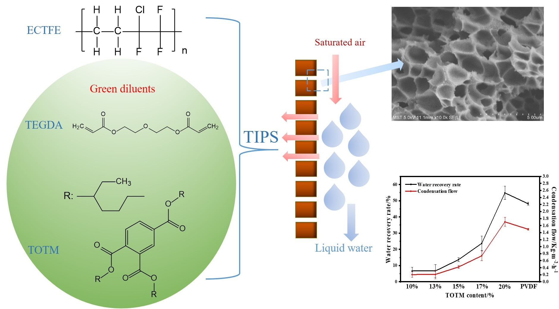
ECTFE Membrane Fabrication Using Green Binary Diluents TEGDA/TOTM and Its Performance in Membrane Condenser


Abstract
:
1. Introduction
2. Materials and Methods
2.1. Materials
2.2. Phase Diagram Parameter Measurement
2.3. ECTFE Membrane Preparation
2.4. Membrane Characterization
2.5. MC Performance of ECTFE Membrane
- (1)
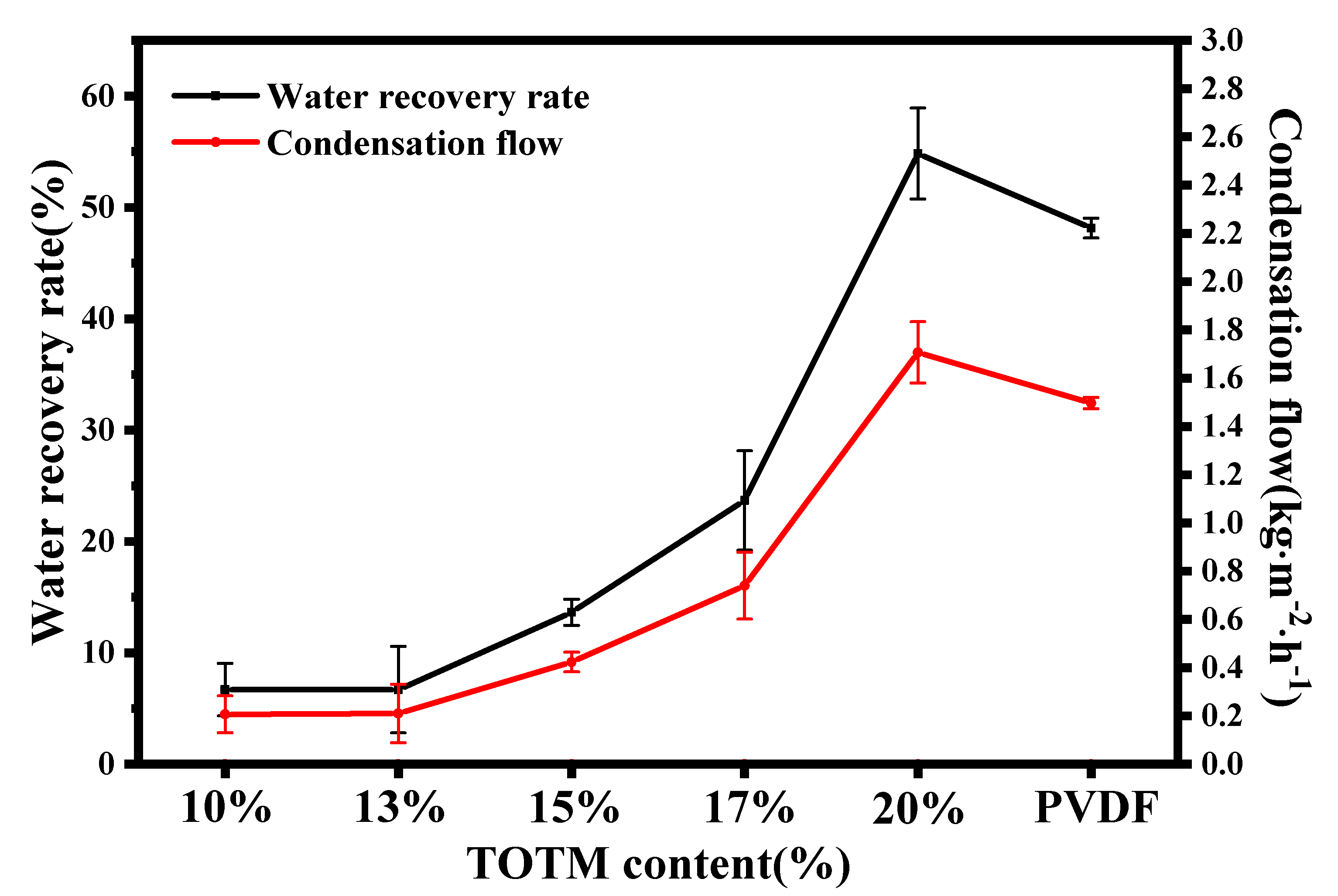
- Condensation flow
- (2)
- Water recovery rate
3. Results and Discussion
3.1. The Effect of Diluent Composition on ECTFE Membranes
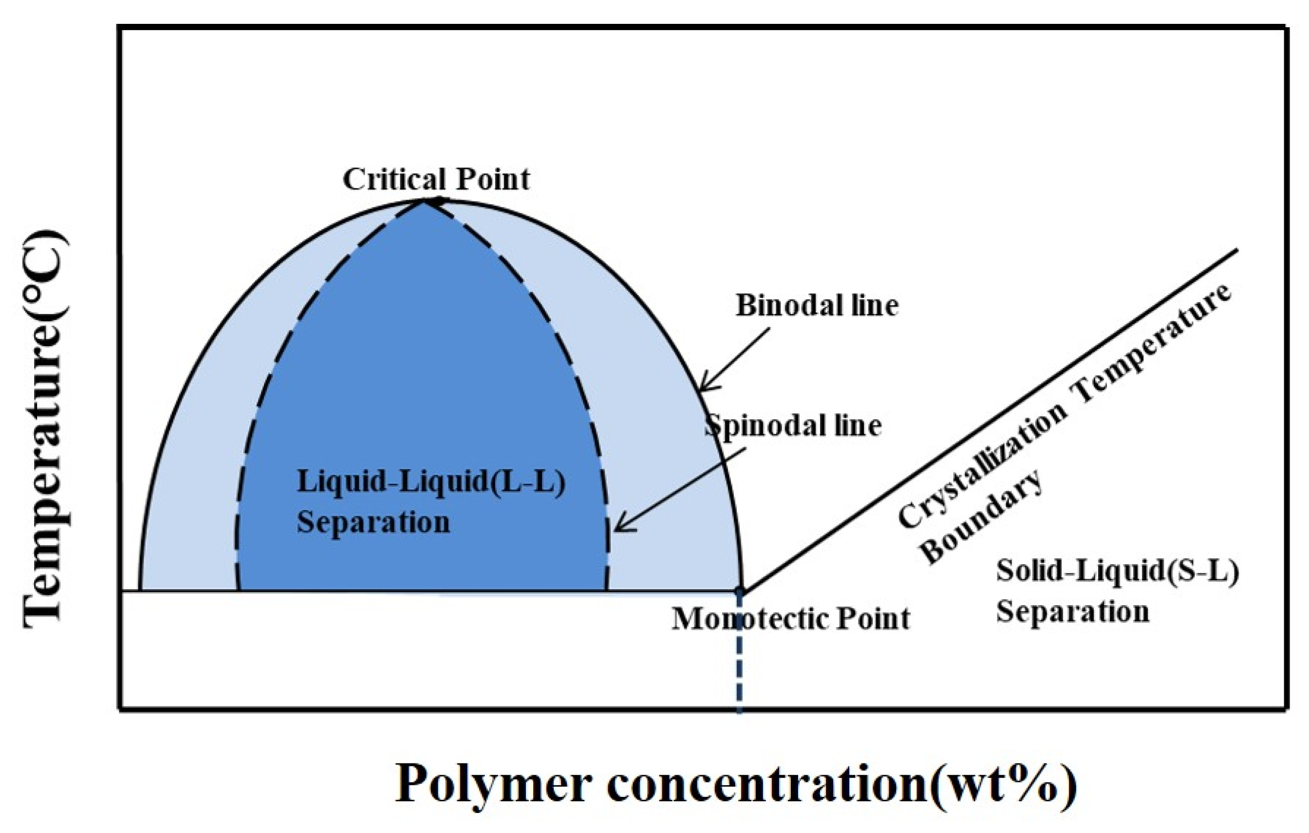
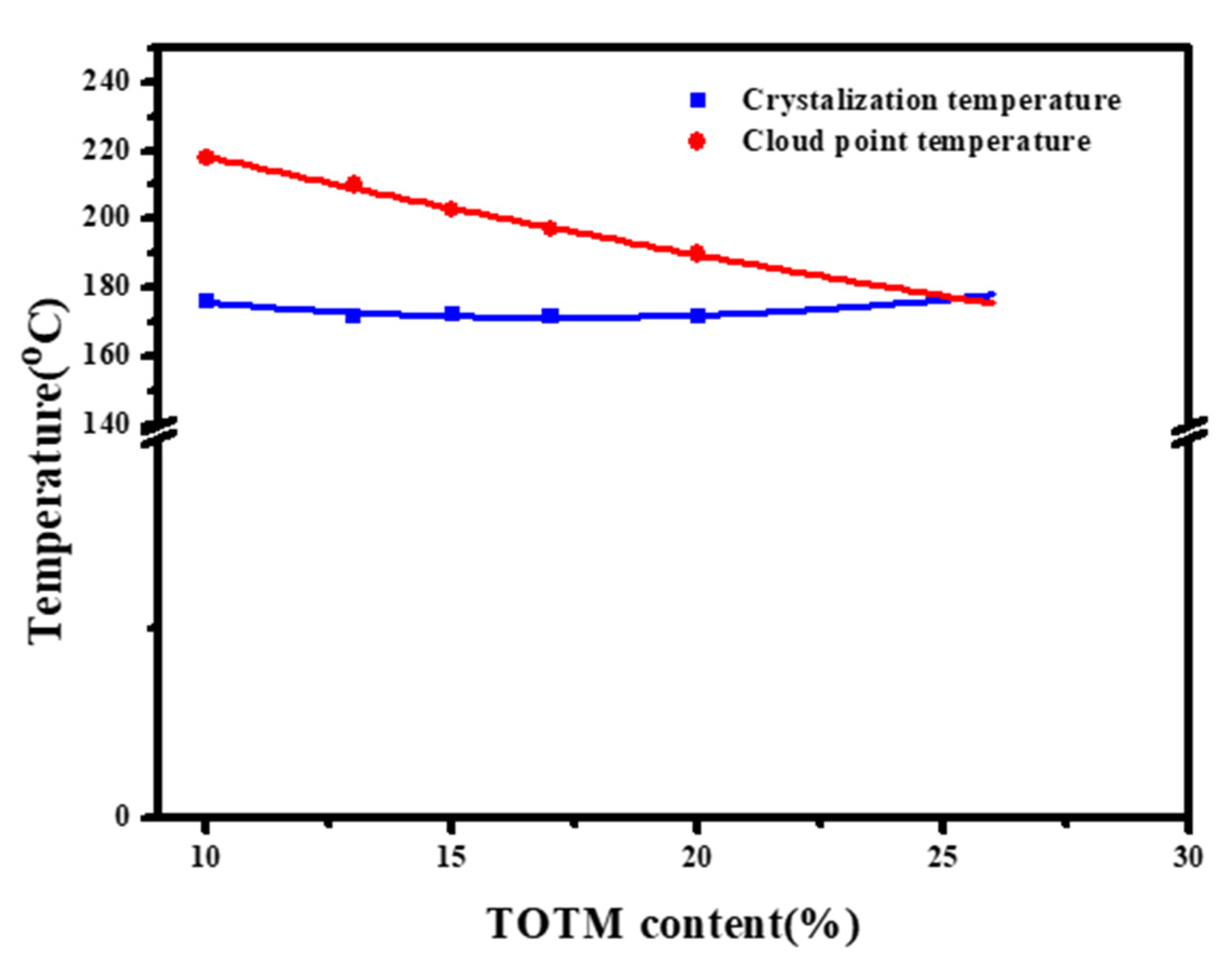
3.1.1. Phase Diagram
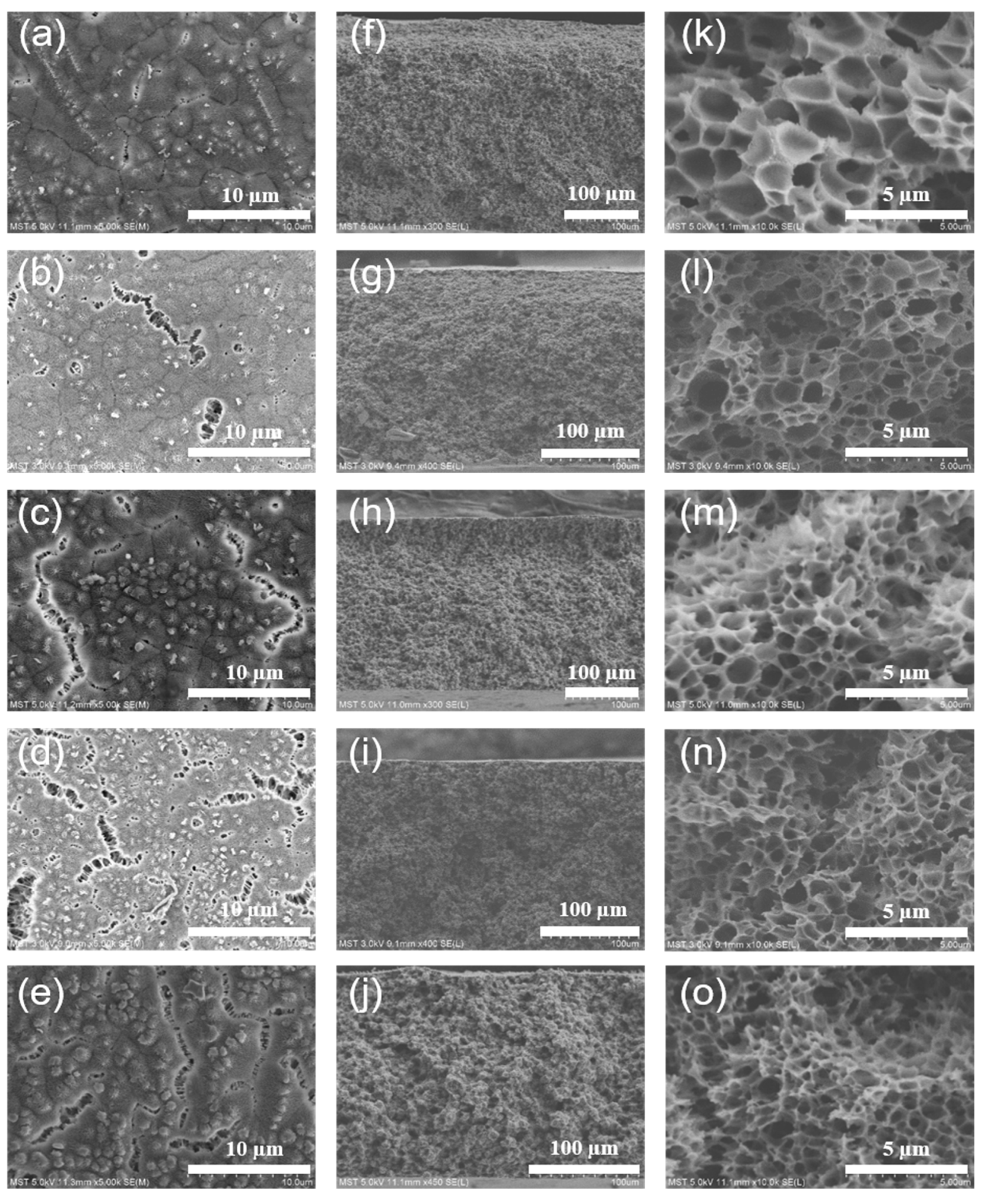
3.1.2. Morphology
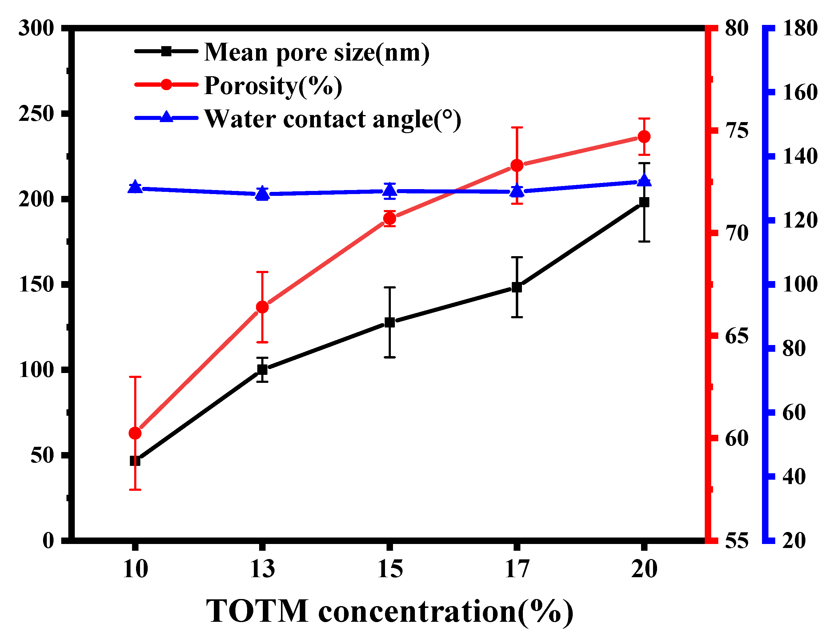
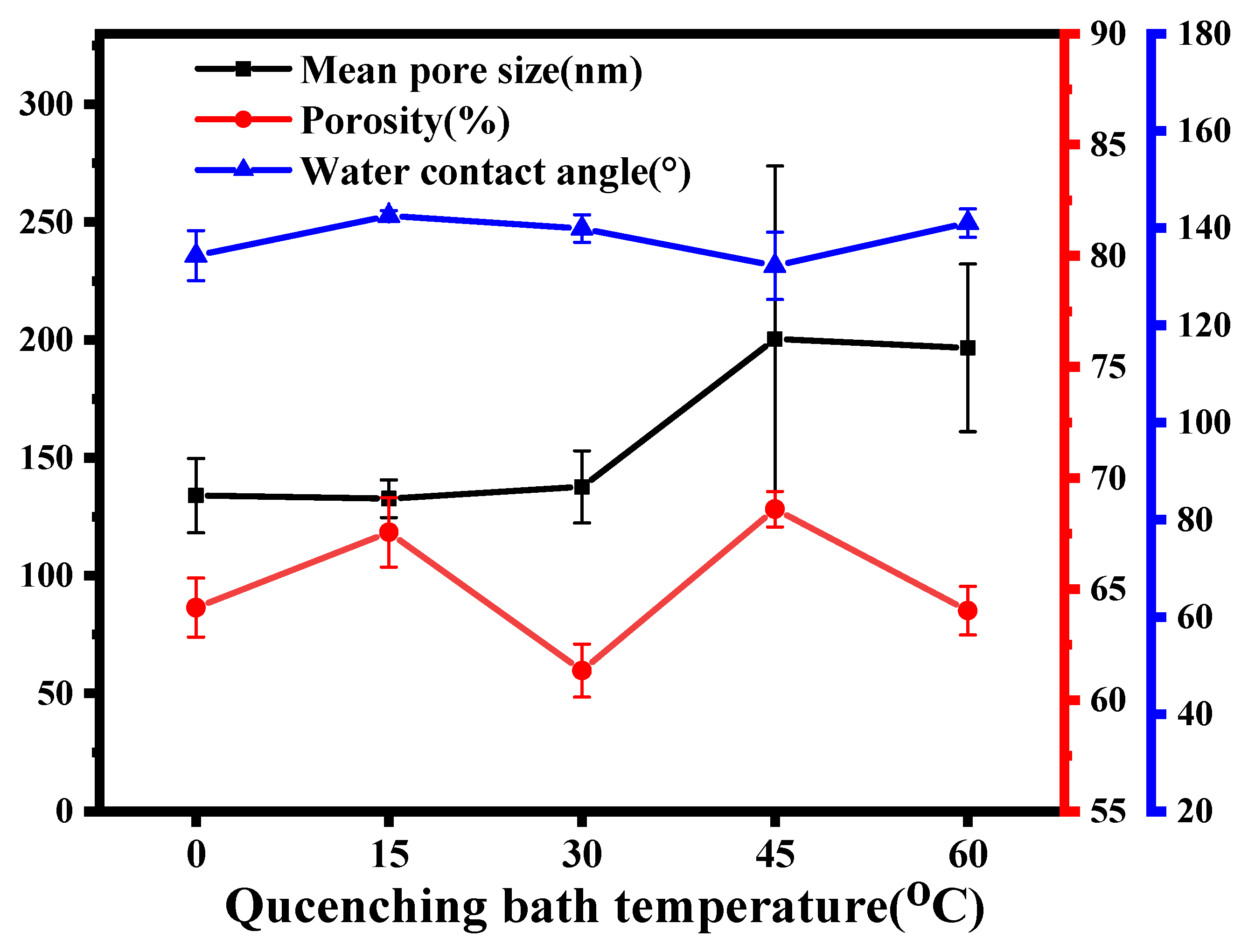
3.1.3. Mean Pore Size, Porosity and Water Contact Angle
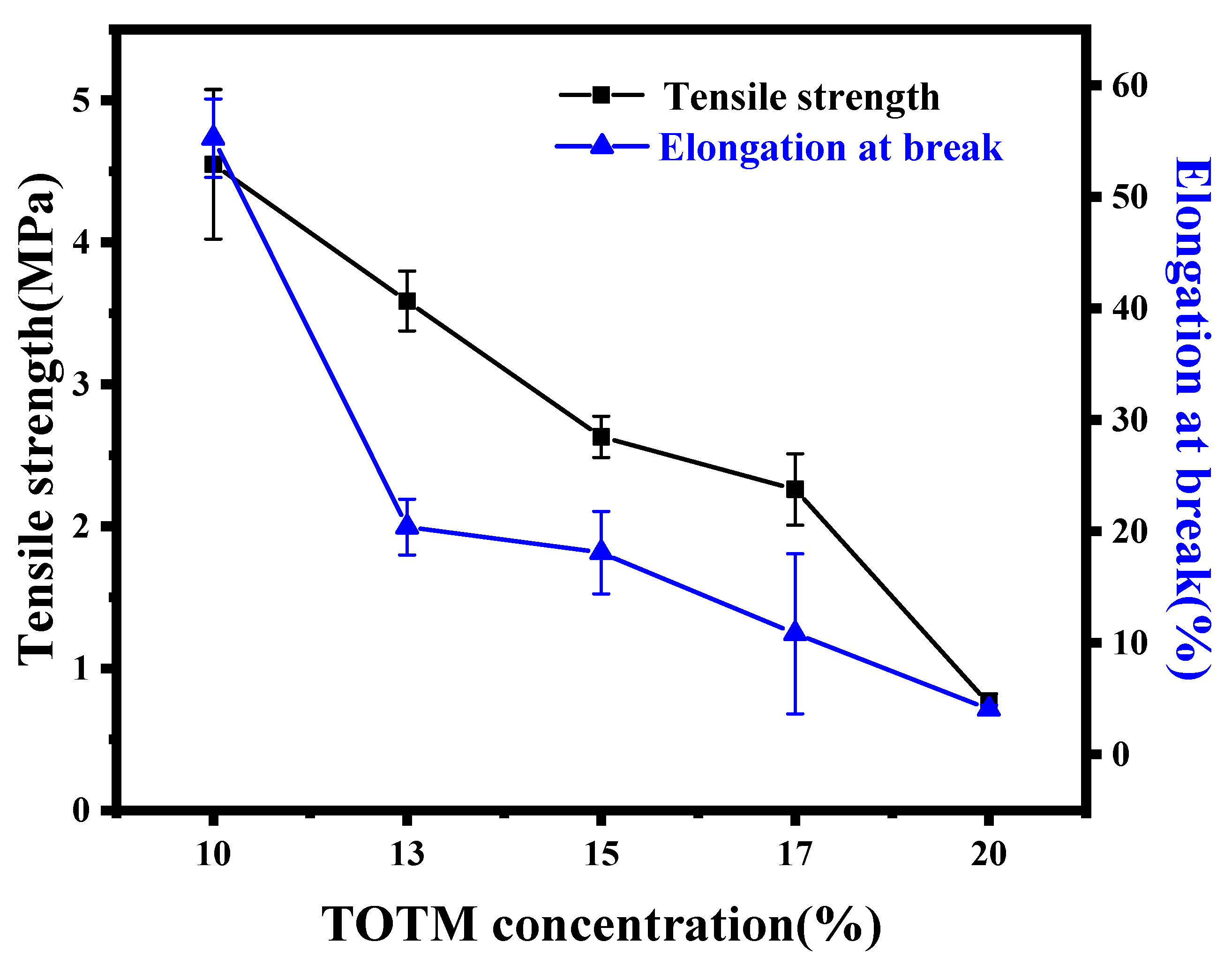
3.1.4. Mechanical Properties
3.1.5. MC Performance
3.2. The Effect of Cooling Rate on ECTFE Membranes
3.2.1. Morphology
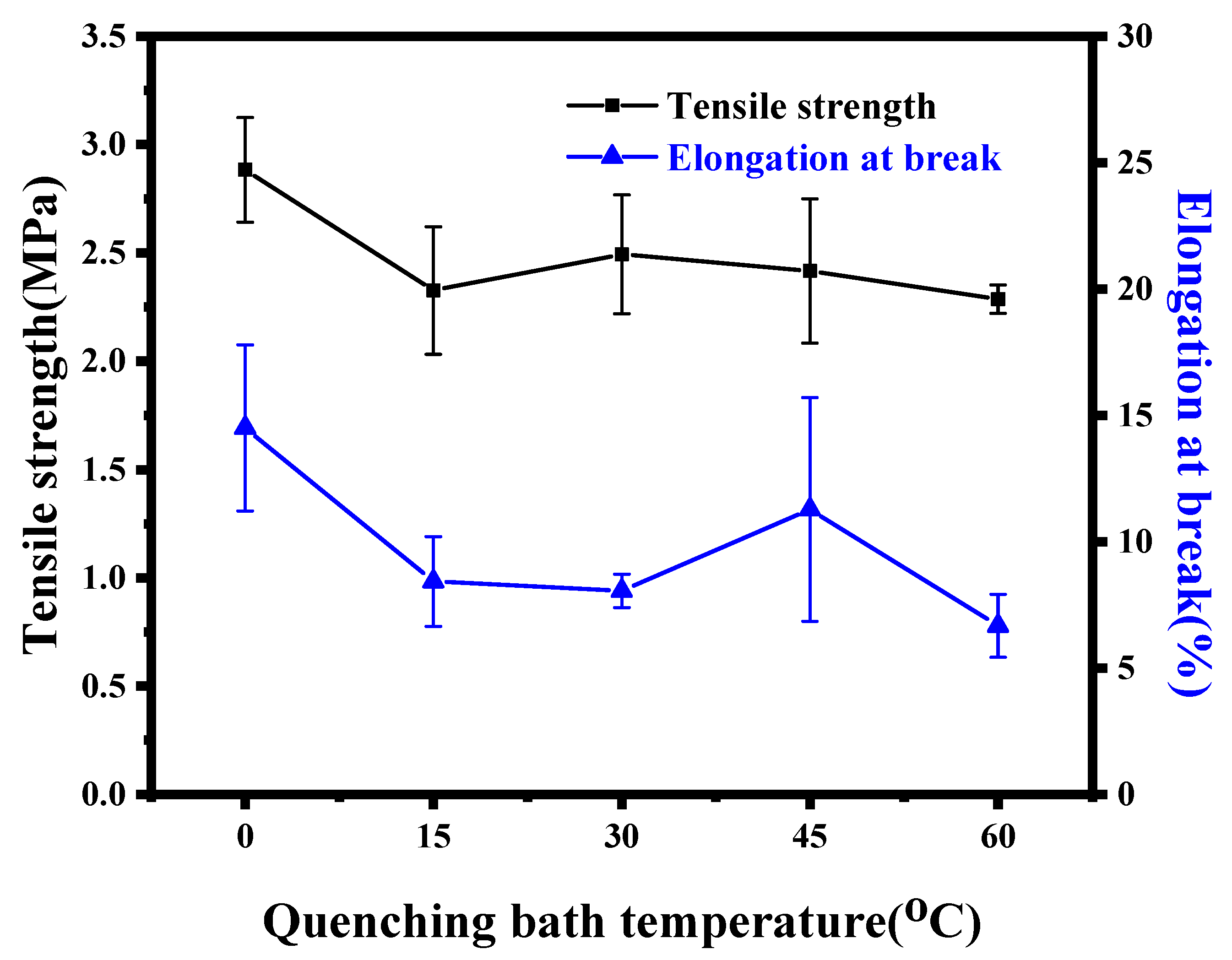
3.2.2. Mechanical Properties
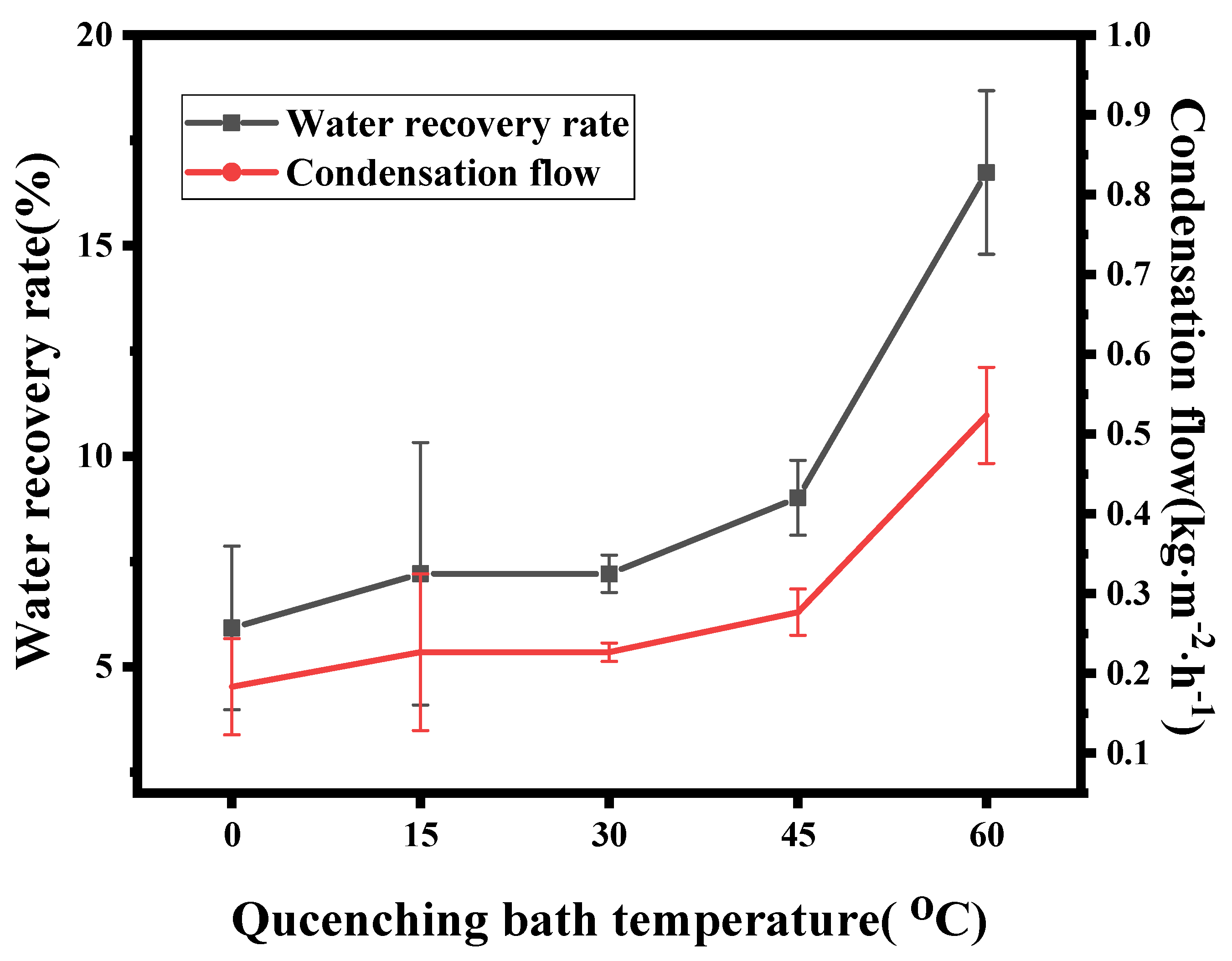
3.2.3. MC Performance
4. Conclusions
Author Contributions
Funding
Institutional Review Board Statement
Informed Consent Statement
Data Availability Statement
Acknowledgments
Conflicts of Interest
Glossary
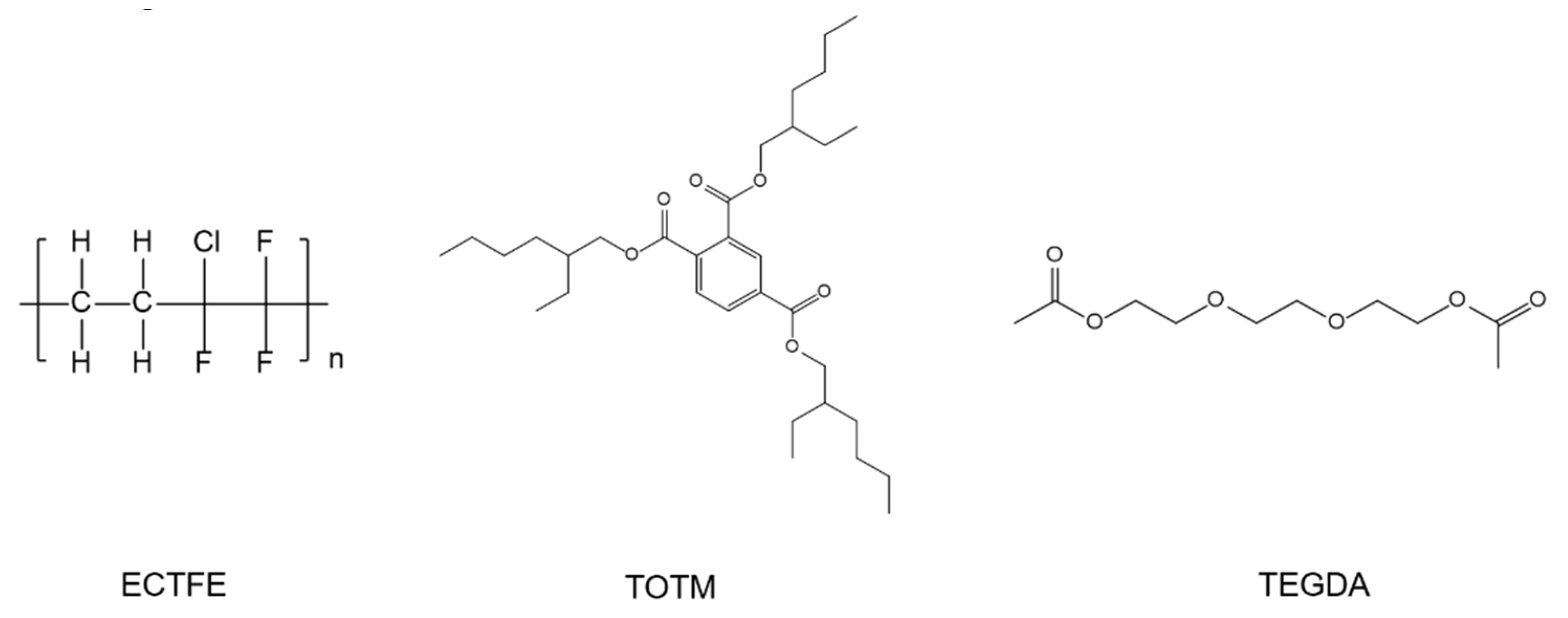
| ECTFE | Poly(ethylene-chlorotrifluoroethylene) |
| MC | Membrane condenser |
| TIPS | Thermally induced phase separation |
| TEGDA | Triglyceride diacetate |
| TOTM | Trioctyl trimellitate |
| DMC | Dense membrane condenser |
| TMC | Transport membrane condenser |
| PVDF | Polyvinylidene fluoride |
| PP | Polypropylene |
| DBM | Dibutyl maleate |
| DEP | Diethyl phthalate |
| GTA | Glycerol triacetate |
| DEHA | Bis(2-ethylhexyl) adipate |
| FESEM | Field emission scanning electron microscope |
| DSC | Differential scanning calorimetry |
| PSDA | Pore size distribution apparatus |
| CA | Contact angle |
| HSP | Hansen solubility parameter theory |
References
- Sijbesma, H.; Nymeijer, K.; Marwijk, R.V.; Heijboer, R.; Potreck, J.; Wessling, M. Flue gas dehydration using polymer membranes. J. Membr. Sci. 2008, 313, 263–276. [Google Scholar] [CrossRef]
- Daal, L.; Kamphuis, H.; Stam, A.; Konings, T.; Huibers, M.; Rijen, S.V.; Ruijter, J.D. Evaluation of Different Water Vapor Capture Technologies and Energy Modeling Results for Membrane Technology; Icapwa: Arnhem, The Netherlands, 2012; Volume 9035, p. 6800. [Google Scholar]
- Michels, B.; Adamczyk, F.; Koch, J. Retrofit of a flue gas heat recovery system at the mehrum power plant. Vgb Powertech-Int. Ed. 2004, 84, 122–129. [Google Scholar]
- Folkedahl, B.C.; Weber, G.F.; Collings, M.E. Water Extraction from Coal-Fired Power Plant Flue Gas; Technical Reports; Office of Scientific & Technical Information: Bismarck, ND, USA, 2006. [Google Scholar]
- Drioli, E.; Macedonio, F. Membrane-Assisted Condenser. Clean Technol. 2018, 1, 2–8. [Google Scholar] [CrossRef] [Green Version]
- Kim, J.F.; Park, A.; Kim, S.-J.; Lee, P.; Cho, Y.; Park, H.; Nam, S.; Park, Y. Harnessing clean water from power plant emissions using membrane condenser technology. ACS Sustain. Chem. Eng. 2018, 6, 6425–6433. [Google Scholar] [CrossRef]
- Macedonio, F.; Brunetti, A.; Barbieri, G.; Drioli, E. Membrane Condenser as a New Technology for Water Recovery from Humidified "Waste" Gaseous Streams. Ind. Eng. Chem. Res. 2013, 52, 1160–1167. [Google Scholar] [CrossRef]
- Cao, J.; Pan, J.; Cui, Z.; Wang, Z.; Drioli, E. Improving efficiency of PVDF membranes for recovering water from humidified gas streams through membrane condenser. Chem. Eng. Sci. 2019, 210, 115234. [Google Scholar] [CrossRef]
- Brunetti, A.; Santoro, S.; Macedonio, F.; Figoli, A.; Drioli, E.; Barbieri, G. Waste Gaseous Streams: From Environmental Issue to Source of Water by Using Membrane Condensers. CLEAN-Soil Air Water 2014, 42, 1145–1153. [Google Scholar] [CrossRef]
- Brunetti, A.; Macedonio, F.; Cui, Z.; Drioli, E. Membrane Condenser as efficient pre-treatment unit for the abatement of particulate contained in waste gaseous streams. J. Environ. Chem. Eng. 2020, 8, 104353. [Google Scholar] [CrossRef]
- Greenberg, A.R.; Krantz, W.B. Fabrication of poly (ECTFE) membranes via thermally induced phase separation. J. Membr. Sci. 2002, 210, 175–180. [Google Scholar]
- Drioli, E.; Santoro, S.; Simone, S.; Barbieri, G.; Brunetti, A.; Macedonio, F.; Figoli, A. ECTFE membrane preparation for recovery of humidified gas streams using membrane condenser. React. Funct. Polym. 2014, 79, 1–7. [Google Scholar] [CrossRef]
- Pan, J.; Xiao, C.; Huang, Q.; Liu, H.; Zhang, T. ECTFE hybrid porous membrane with hierarchical micro/nano-structural surface for efficient oil/water separation. J. Membr. Sci. 2017, 524, 623–630. [Google Scholar] [CrossRef]
- Gu, M.; Zhang, J.; Wang, X.; Tao, H.; Ge, L. Formation of poly(vinylidene fluoride) (PVDF) membranes via thermally induced phase separation. Desalination 2006, 192, 160–167. [Google Scholar] [CrossRef]
- Cui, Z.L.; Cheng, Y.M.; Xu, K.; Yue, J.; Zhou, Y.; Li, X.G.; Wang, Q.; Sun, S.P.; Wang, Y.; Wang, X.Z.; et al. Wide liquid-liquid phase separation region enhancing tensile strength of poly(vinylidene fluoride) membranes via TIPS method with a new diluent. Polym. Int. J. Sci. Technol. Polym. 2018, 141, 46–53. [Google Scholar] [CrossRef]
- Yang, J.; Wang, X.L.; Tian, Y.; Lin, Y.; Tian, F. Morphologies and crystalline forms of polyvinylidene fluoride membranes prepared in different diluents by thermally induced phase separation. J. Polym. Sci. Part B Polym. Phys. 2010, 48, 2468–2475. [Google Scholar] [CrossRef]
- Karkhanechi, H.; Rajabzadeh, S.; Nicolò, E.; Usuda, H.; Shaikh, A.R.; Matsuyama, H. Preparation and characterization of ECTFE hollow fiber membranes via thermally induced phase separation (TIPS). Polymer 2016, 97, 515–524. [Google Scholar] [CrossRef]
- Pan, J.; Xiao, C.F.; Huang, Q.L.; Liu, H.L.; Hu, J. ECTFE porous membranes with conveniently controlled microstructures for vacuum membrane distillation. J. Mater. Chem. A 2015, 3, 23549–23559. [Google Scholar] [CrossRef]
- Liu, G.; Pan, J.; Xu, X.; Wang, Z.; Cui, Z. Preparation of ECTFE porous membrane with a green diluent TOTM and performance in VMD process. J. Membr. Sci. 2020, 612, 118375. [Google Scholar] [CrossRef]
- Roh, I.J.; Ramaswamy, S.; Krantz, W.B.; Greenberg, A.R. Poly(ethylene chlorotrifluoroethylene) membrane formation via thermally induced phase separation (TIPS). J. Membr. Sci. 2010, 362, 211–220. [Google Scholar] [CrossRef]
- Kim, J.F.; Kim, J.H.; Lee, Y.M.; Drioli, E. Thermally induced phase separation and electrospinning methods for emerging membrane applications: A review. AIChE J. 2016, 62, 461–490. [Google Scholar] [CrossRef]
- Hansen, C.M. Hansen Solubility Parameters: A User’s Handbook, CRC Press: Boca Raton, FL, USA, 2007.
- Xu, K.; Cai, Y.; Hassankiadeh, N.T.; Cheng, Y.; Li, X.; Wang, X.; Wang, Z.; Drioli, E.; Cui, Z. ECTFE membrane fabrication via TIPS method using ATBC diluent for vacuum membrane distillation. Desalination 2019, 456, 13–22. [Google Scholar] [CrossRef]
- Umakoshi, K.; Gonzales, R.R.; Kato, N.; Zhang, P.F.; Ono, T.; Matsuyama, H. Effect of polymer-solvent compatibility on polyamide hollow fiber membranes prepared via thermally induced phase separation. Colloids Surf. A Physicochem. Eng. Asp. 2022, 642, 128704. [Google Scholar] [CrossRef]
- Rajabzadeh, S.; Maruyama, T.; Sotani, T.; Matsuyama, H. Preparation of PVDF hollow fiber membrane from a ternary polymer/solvent/nonsolvent system via thermally induced phase separation (TIPS) method. Sep. Purif. Technol. 2008, 63, 415–423. [Google Scholar] [CrossRef]
- Wu, Q.Y.; Wan, L.S.; Xu, Z.K. Structure and performance of polyacrylonitrile membranes prepared via thermally induced phase separation. J. Membr. Sci. 2012, 409–410, 355–364. [Google Scholar] [CrossRef]
- Lin, Y.K.; Chen, G.; Yang, J.; Wang, X.L. Formation of isotactic polypropylene membranes with bicontinuous structure and good strength via thermally induced phase separation method. Desalination 2009, 236, 8–15. [Google Scholar] [CrossRef]
- Pan, J.; Chen, K.; Cui, Z.L.; Bamaga, O.; Albeirutty, M.; Alsaiari, A.O.; Macedonio, F.; Drioli, E. Preparation of ECTFE Porous Membrane for Dehumidification of Gaseous Streams through Membrane Condenser. Membranes 2022, 12, 65. [Google Scholar] [CrossRef]
- Lu, J.; Kim, S.G.; Lee, S.; Oh, I.K. A Biomimetic Actuator Based on an Ionic Networking Membrane of Poly(styrene-alt-maleimide)-Incorporated Poly(vinylidene fluoride). Adv. Funct. Mater. 2008, 18, 1290–1298. [Google Scholar] [CrossRef]
- Fu, L.; Hashim, N.A.; Liu, Y.; Abed, M.; Li, K. Progress in the production and modification of PVDF membranes. Fuel Energy Abstr. 2011, 375, 1–27. [Google Scholar]
- Wang, T.; Yue, M.; Qi, H.; Feron, P.H.; Zhao, S. Transport membrane condenser for water and heat recovery from gaseous streams: Performance evaluation. J. Membr. Sci. 2015, 484, 10–17. [Google Scholar] [CrossRef]


| The Operating Conditions | Value |
|---|---|
| N2 flow rate (L/min) | 0.5 |
| Feed gas temperature (°C) | 50 |
| Feed gas relative humidity (%) | 100 |
| Cold sweep gas temperature ΔT (°C) | 20 |
| Operation time (h) | 1 |
| Membrane area (m2) | 8.317 × 10⁻⁴ |
| δd (MPa 1/2) | δp (MPa 1/2) | δh (MPa 1/2) | R (MPa 1/2) | |
|---|---|---|---|---|
| ECTFE | 19.5 | 7.3 | 1.7 | - |
| DEP | 17.6 | 9.6 | 4.5 | 5.25 |
| GTA | 16.5 | 4.5 | 9.1 | 9.93 |
| TOTM | 16.66 | 8.55 | 6.03 | 8.54 |
| TEGDA | 16.45 | 2.14 | 9.78 | 11.36 |
| DBM | 16.5 | 6.1 | 7.2 | 8.23 |
| Membrane | Membrane Area (m2) | Feed Gas Relative Humidity (%) | Feed Flow Rate (L⋅min−1) | Feed Gas Temperature (°C) | Water Recovery Rate (%) | Condensation Flow (kg·m−2·h−1) | Reference |
|---|---|---|---|---|---|---|---|
| Ceramic membrane-KRICT 100 | 0.00532 | 50,80 | 1–6 | 60–80 | Not mentioned | 0.5–11 | Kim et al. [6] |
| Modified PVDF membrane M-40L | 0.00252 | 60,95 | 1.0,2.0 | 50 | 5.7–18.85 | 0.15–0.35 | Cao et al. [8] |
| Flat ECTFE membrane | 0.004 | 100 | 0.076–0.38 | 55,65 | 35–55 | Not mentioned | Drioli et al. [12] |
| Flat ECTFE membrane | 0.001256 | 100 | 1.5 | 55 | 10–17 | 1.1–1.8 | Pan et al. [28] |
| Ceramic membrane | 0.0021 | 100 | 2 | 45–85 | 25–50 | 2–15 | Wang et al. [31] |
| Flat ECTFE membrane (TOTM content is 15%) | 0.000832 | 100 | 0.5 | 50 | 13.65 | 0.42 | This work |
Publisher’s Note: MDPI stays neutral with regard to jurisdictional claims in published maps and institutional affiliations. |
© 2022 by the authors. Licensee MDPI, Basel, Switzerland. This article is an open access article distributed under the terms and conditions of the Creative Commons Attribution (CC BY) license (https://creativecommons.org/licenses/by/4.0/).
Share and Cite
Yu, S.; Huang, Y.; Zhang, L.; Wang, Q.; Wang, Z.; Cui, Z.; Drioli, E. ECTFE Membrane Fabrication Using Green Binary Diluents TEGDA/TOTM and Its Performance in Membrane Condenser. Membranes 2022, 12, 757. https://doi.org/10.3390/membranes12080757
Yu S, Huang Y, Zhang L, Wang Q, Wang Z, Cui Z, Drioli E. ECTFE Membrane Fabrication Using Green Binary Diluents TEGDA/TOTM and Its Performance in Membrane Condenser. Membranes. 2022; 12(8):757. https://doi.org/10.3390/membranes12080757
Chicago/Turabian StyleYu, Songhong, Yu Huang, Lixun Zhang, Qian Wang, Zhaohui Wang, Zhaoliang Cui, and Enrico Drioli. 2022. "ECTFE Membrane Fabrication Using Green Binary Diluents TEGDA/TOTM and Its Performance in Membrane Condenser" Membranes 12, no. 8: 757. https://doi.org/10.3390/membranes12080757