
Roles of Sulfites in Reverse Osmosis (RO) Plants and Adverse Effects in RO Operation

LG Chem Japan Co., Ltd., Kyobashi Trust Tower 12F, 2-1-3 Kyobashi Chuo-ku, Tokyo 104-0031, Japan
Membranes 2022, 12(2), 170; https://doi.org/10.3390/membranes12020170
Submission received: 27 December 2021
/
Revised: 21 January 2022
/
Accepted: 21 January 2022
/
Published: 31 January 2022
Abstract
:More than 60 years have passed since UCLA first announced the development of an innovative asymmetric cellulose acetate reverse osmosis (RO) membrane in 1960. This innovation opened a gate to use RO for commercial use. RO is now ubiquitous in water treatment and has been used for various applications, including seawater desalination, municipal water treatment, wastewater reuse, ultra-pure water (UPW) production, and industrial process waters, etc. RO is a highly integrated system consisting of a series of unit processes: (1) intake system, (2) pretreatment, (3) RO system, (4) post-treatment, and (5) effluent treatment and discharge system. In each step, a variety of chemicals are used. Among those, sulfites (sodium bisulfite and sodium metabisulfite) have played significant roles in RO, such as dechlorination, preservatives, shock treatment, and sanitization, etc. Sulfites especially became necessary as dechlorinating agents because polyamide hollow-fiber and aromatic thin-film composite RO membranes developed in the late 1960s and 1970s were less tolerable with residual chlorine. In this review, key applications of sulfites are explained in detail. Furthermore, as it is reported that sulfites have some adverse effects on RO membranes and processes, such phenomena will be clarified. In particular, the following two are significant concerns using sulfites: RO membrane oxidation catalyzed by heavy metals and a trigger of biofouling. This review sheds light on the mechanism of membrane oxidation and triggering biofouling by sulfites. Some countermeasures are also introduced to alleviate such problems.
1. Introduction
Reverse osmosis (RO) is a liquid-phase pressure-driven separation process in which applied transmembrane pressure causes selective movement of solvent against its osmotic pressure difference [1]. RO is now ubiquitous in water treatment and has been used for various applications, including seawater desalination, municipal water treatment, wastewater reuse, ultra-pure water (UPW) production, and industrial process waters, etc. Furthermore, RO is anticipated to contribute to the United Nation’s Sustainable Development Goals (SDGs), especially in Goal 6: Clean Water and Sanitation. Then, in Goal 6.a, the following actions are raised: expand international cooperation and capacity building support to developing countries in water and sanitation-related activities and programs. These include water harvesting, desalination, water efficiency, wastewater treatment, recycling, and reuse technologies [2,3].
Regarding RO membrane development, more than 60 years have passed since UCLA first announced the development of an innovative asymmetric cellulose acetate RO membrane in 1960. Furthermore, new generation polyamide hollow fiber RO and thin-film composite (TFC) aromatic polyamide RO membranes were developed one after another in the early 1970s and 1977. As a result of continuous improvements, the TFC RO membrane performance has been greatly improved, and it is now widely used for a variety of applications. As for the future membrane desalination technology, three technologies were raised in National Geographic, April 2010 [4]. These three technologies promised to reduce the energy requirement of desalination up to 30% are forward osmosis, carbon nanotubes, and biomimetics. Among those, nanoporous membranes, including porous graphene, carbon nanotubes, and graphene oxide, etc., attracted much attention from academic researchers [5]. However, it does not seem easy to produce commercial-based defect-free RO membranes with nanoporous materials. A way of overcoming material limitations for RO applications is to utilize composite materials comprising nanoporous materials within a polymer matrix. The use of thin-film nanocomposite (TFN) membranes for water purification was first described for BWRO membranes by Jeong et al. [6]. After that, many research works on the TFN membranes have been conducted [7,8].
An RO system typically consists of five major unit processes: (1) intake system, (2) pretreatment, (3) RO system, (4) post-treatment, and (5) effluent treatment and discharge system, as illustrated in Figure 1. RO membranes and elements are critically important to separate water from organic and inorganic impurities in the RO system. Several RO membranes exist, such as aromatic polyamide, and cellulose triacetate, etc., and are fabricated into the spiral-wound, hollow fiber, tubular, plate and frame elements. Among them, thin-film composite (TFC) and thin-film nanocomposite (TFN) spiral-wound elements have been commonly used in water treatment. However, a series of pretreatment is necessary to supply feedwaters to RO elements and meet specific requirements for the spiral wound elements, such as silt density index (SDI) < 5 and residual chlorine < 0.1 mg/L, etc.
It is observed that a variety of chemicals have to be used in each process steps shown in Figure 1. In the intake system, chlorine is sometimes applied continuously or intermittently to protect the intake and pretreatment equipment from bacteria and algae growth. The following chemicals are used in the pretreatment step: coagulants, flocculants, dechlorination agents, and antiscalants, etc. When using low-pressure membranes (MF/UF) as the pretreatment, backwash chemicals, such as sodium hypochlorite (NaOCl) and acid/caustic for chemical-enhanced backwash (CEB), are used. In the RO system, cleaning in place (CIP) chemicals, RO element storage chemicals (preservatives), and biocides are used.
However, it should be noted that the use of these chemicals depends strongly on the feedwater characteristics and operating conditions. For example, some well water treatment plants are only equipped with cartridge filters with minimal chemical dosage [9,10,11]. It is reported that the 360 m3/d capacity BWRO plant in Las Palmas, Canary Islands, Spain, has been operating for more than nine years by only dosing 6 mg/L of antiscalant [12]. Similarly, Lagartos et al. [13] reported Malta’s Pembroke seawater desalination plant. The plant can produce 54,000 m3/d of water. The water intake comes from beach wells with a silt density index below 1. The pH is adjusted with sulfuric acid down to 6.7 to protect the pipework and prevent scaling. After pH adjustment, cartridge filters are installed upstream of the RO unit. It is reported that the cleaning in place (CIP) frequency varies between 6 and 10 months, depending on the train condition and time of operation.
These chemicals might be categorized into the following six (6) items [14]: (1) cleaning agents, (2) dechlorinants, (3) biocides, (4) pH adjustors, (5) coagulants/flocculants, and (6) antiscalants. As for dechlorinants, either sodium metabisulfite (SMBS) or sodium bisulfite (SBS) is used, and it was estimated as roughly 12–15% of the membrane chemicals market. However, SBS is used for many other applications in the RO unit processes, as shown in Figure 2.
The most critical role of SBS is dechlorination. As the TFC/TFN membranes are less tolerable to chlorine, the residual chlorine must be removed prior to entering the RO unit. The next key application is a use for an RO element preservative for shipping elements and during plant shutdown. Several other SBS applications include deoxygenation, shock treatment as a biostatic agent, and CIP chemical, etc. Thus, SBS can be considered an essential chemical for RO processes. However, some adverse effects have been reported. For example, it was reported that under specific conditions, i.e., heavy metals, dissolved oxygen, etc. SBS degrades RO membranes [15], or SBS triggers biofouling when overdosing [16].
In terms of dechlorination and preservative roles, there have been many reports on how to use SBS and control its dosing amount. However, fewer reports were observed for the membrane degradation and inducing biofouling. Therefore, this review article aims to shed light on some adverse effects of SBS and identify their mechanisms in addition to common application fields.
2. Chemical Properties and Handling Precautions of Sodium Bisulfite (SBS)
SBS is a chemical compound with the chemical formula NaHSO3 that has a reduction ability. Thus, it is used to remove residual chlorine in water/wastewater and industrial applications. It is also used as an oxygen scavenger in boiler water treatment. In the food industry, SBS is used as a preservative. Some fundamental chemical properties are shown in Table 1.
SBS is a weakly acidic species with a pKa of 6.97. Thus, SBS exists as a mixture with sodium sulfite in the neutral pH range as shown below:
SBS is available as a solution of various concentrations or is produced by dissolving SMBS (Na2S2O5). When SMBS is dissolved in water, SBS is formed:
SMBS solution has a pH of 4.6 at 1.0% (by weight) solution strength [17]. It is demonstrated that sulfur dioxide (SO2) vapor pressure is increased at lower pH of less than 5.5 for a 30% active SBS solution [18]. It is also demonstrated that SO2 generation begins at pH 7.0, and a fair amount of SO2 gas is generated below pH 4.0 according to the following equilibrium [19].
HSO3− ↔ SO32− + H+
Na2S2O5 + H2O → 2NaHSO3
SO2 + H2O ↔ HSO3− + H+
If SMBS is used to produce SBS, SO2 is generated when mixing with water. Therefore, a dilution tank must have a vent [20]. If more than one (1) dilution tank is installed, they will be interconnected and extracted to a safe location. Furthermore, SBS reacts with oxygen during storage. The deoxygenation reaction increases sulfate concentration and decreases pH, further inducing SO2 off-gas generation from the storage tank. Therefore, an air extraction system must be installed in the area and a vent must be directed outdoors.
2HSO3− + O2 → 2SO42− + 2H+
Releasing hazardous fumes can be reduced by using sodium sulfite (Na2SO3) solution or increasing the pH of the SBS solution. However, it is limited in its day tank solubility to about 12%. Even at lower concentrations, constant mixing within the day tank will be required [21].
The food-grade SMBS powder has a shelf life of approximately 6–12 months. However, as the SMBS/SBS solutions are not stable to air and react with oxygen, the shelf life of the solutions is shortened depending on concentrations. Therefore, the following guideline is suggested from RO membrane manufacturers as shown in Table 2.
The solubility of SBS is significantly reduced at a temperature of less than 10 °C [18]. Thus, higher concentrations tend to crystallize at relatively warm temperatures (≤6 °C), causing blockages in dosing pump suction and delivery lines, and lower concentrations of around 20 wt% are sometimes preferred for this reason [25]. Thus, it is recommended that SBS solution should always be stored in a temperature range of 15–35 °C [18]. Kunisada et al. [26] encountered the SBS crystallization problem for an 800 m3/d pilot plant operation in Chigasaki, Japan. When the temperature was close to 0 °C, SBS was crystallized, which caused blockage of the chemical injection line and pump. Therefore, several measures were taken but could not resolve the issue completely. Finally, it was decided that the 35% SBS solution was diluted to 30% by installing an additional 4 m3 tank.
In case of spillages and safely disposing of SBS solutions, special care has to be taken. It is guided that any spillages should be neutralized with soda ash to prevent SO2 emission and then be oxidized to neutral sulfate with sodium hypochlorite [25]. On some occasions, higher concentration SBS solutions are discharged from RO systems, including startup time after RO unit preservation and shock treatment during RO operation. In some RO plants, aeration is applied to neutralize SBS [27,28,29,30]. For example, in an RO plant producing boiler make-up water, a wastewater treatment unit was installed. When the RO plant is shut down, the RO train is preserved with about 500 mg/L of SBS. Therefore, when the RO starts operation, a large amount of SBS is discharged into the brine. An aeration unit was equipped to address an issue of a regulated COD. During aeration, the pH is adjusted to 6.0–8.5 with caustic soda. As the aeration is proceeding, SBS concentration reduction is stopped at about 10 mg/L. However, since the COD is reached about 1.5 mg/L at this stage, it can be released. A similar treatment was implemented in the 40,000 m3/d seawater desalination plant in Okinawa, Japan [28].
3. Removal of Oxidative Disinfectants: Chlorine, Chloramine, Chlorine Dioxide, and DBNP
Chlorine disinfection has been applied to protect intake facility and pretreatment equipment from biological growth and reduce the risk of biofouling in RO modules/elements. When RO membranes were first commercially used, cellulose acetate (CA) was a primary RO material. As the CA membranes have a certain degree of chlorine resistance up to a maximum of 1.0 ppm [31], much attention was not paid to dechlorination. However, soon after the aramid hollow fiber RO membrane was put into practical use, the dechlorination process became an important issue because of its poor chlorine resistance [32]. Similar dechlorination conditions were applied to the newly developed TFC membranes, although the TFC polyamide membranes were considered to have some chlorine tolerance (1000–2000 ppm·hr) [23]. Even though dechlorination is of critical importance for RO operation and maintenance (O & M), it is reported that nearly 18% of RO elements failure was attributed to membrane oxidation during element autopsy studies [33,34]. Thus, dechlorination is now a crucial pretreatment step due to their insufficient chlorine resistance.
Currently, low-pressure (LP) membranes have been used as pretreatment of RO. In this case, a high chlorine concentration is used for backwash water and CIP chemical when the LP membranes are used. Thus, residual chlorine in the LP membrane permeate has to be removed before entering the RO. Furthermore, some other types of disinfectants, such as chloramine and chlorine dioxide, have been considered to address disinfection by-product (DBPs) formation by chlorine. Generally, these disinfectants have less oxidative power and might be dosed to RO continuously or intermittently. However, it is reported that the disinfectants oxidize RO membranes under specific conditions. For example, it is known that chloramine is converted to bromamine in seawater and that bromamine causes RO membrane oxidation [35]. Thus, when chloramine and chlorine dioxide are used in the RO process, those oxidants may need to be removed.
As mentioned, several types of oxidants are used in pretreatment, CIP, and disinfection, etc. In addition to preventing RO membrane oxidation, the residual oxidants must be removed prior to discharge to protect the watershed environment. In this section, oxidative chemical removal technologies with sulfites will be discussed.
3.1. Dechlorination
Dechlorination has been achieved by an activated carbon (AC) bed or sulfite chemicals in RO processes. However, carbon filtration is typically not recommended for dechlorination of RO feed water unless the concentrations of organics are high enough to warrant its use and other circumstances prohibit the use of sulfites [24,36]. Usage of AC filters has the following concerns in RO O&M: aiding the growth of microbes and sloughing off carbon fines. Thus, sulfite compounds, sodium sulfite (Na2SO3), SBS (NaHSO3), and SMBS (Na2S2O5) are used for dechlorination. These sulfites react with chlorine as follows:
Sodium sulfite: Na2SO3 + Cl2 + H2O → Na2SO4 + 2HCl
Sodium bisulfite (SBS): NaHSO3 + Cl2 + H2O → NaHSO4 + 2HCl
Sodium metabisulfite (SMBS): Na2S2O5 + 2Cl2 + 3H2O → 2NaHSO4 + 4HCl
Based on these reactions, theoretical dosages for different sulfites are summarized in Table 3.
SBS and SMBS have been commonly utilized in RO dechlorination among those sulfites. When using SMBS, non-cobalt catalyzed and food-grade quality SMBS should be used. It is reported that cobalt-catalyzed SBS for dechlorination resulted in the degradation of polyamide membranes [31]. Regarding the necessary dosing amount in the field, a stoichiometric dosage of SBS was insufficient for complete dechlorination. Thus, an excess of the stoichiometric dosage (mg dechlorination agent/mg Cl2) is needed. However, it was unclear how much extra dosing should be applied to actual plants. A few research works were conducted by focusing on this issue and measuring the reaction kinetics of various reducing agents under different stoichiometric dosing rates [38,39,40]. The findings suggest that the three stoichiometric dosage of SBS was successful in achieving complete dechlorination. It was also found that organic and inorganic matter may be responsible for inhibiting dechlorination at low stoichiometric dosages of SBS [39]. Apart from these experimental results, 10% excess dechlorinating chemicals are suggested for common water and wastewater treatment [37]. However, in the case of RO application, a higher amount of sulfites dosage has been recommended due to a concern about membrane oxidation and stability of sulfites during storage. Almost all RO-related books and manufacturers’ technical bulletins state an appropriate amount of SBS dosing for dechlorination. The suggested dosing amount so far is summarized in Table 4.
Typically, 2–3 mg of SMBS are suggested to remove 1 mg of chlorine. Using three to five times the stoichiometric amount of SBS was suggested for the aramid hollow fiber RO [43]. In Table 4, the stoichiometric amount ratio (dosing amount/stoichiometric amount) is also listed. When determining the actual dosage, the stoichiometric amount ratio might be considered a safety factor [36]. The following safety factors are generally applied: 1.2–2.0 [46] and 1.5–2.0 [36]. One technical bulletin mentioned that more SMBS might be required for seawater when dissolved oxygen is present [23]. This suggestion may have referred to an uncommon event in the Middle East. The Umm Lujj 2 Desalination Plant is located on the Red Sea Coast 154 km north of Yanbu. The Umm Lujj 2 was designed to produce 4400 m3 per day of drinking water and started in 1986. A 28-day trial using 0.5 ppm chlorination and dechlorination accompanying 5 ppm SBS was unsuccessful [47]. Even with adopting a higher safety factor of 6.8, damage to chlorine-sensitive membranes was found, and this degradation resulted in premature failure of membrane modules [48]. A membrane autopsy revealed that the membrane was attacked by halogen compounds [49]. Osta et al. [47] attributed this phenomenon to a fast reaction with oxygen as one of the reasons due to: (a) metals in seawater serving as catalysts, (b) high ionic strength, (c) specific pH, (d) high bicarbonate concentration, and (e) high temperature. As for heavy metals, the raw seawater of the Red Sea was analyzed along with troubleshooting efforts for CTA membrane oxidation in the Jeddah Phase I plant [50]. A higher copper ion concentration of 1.8 ppb was detected than the standard concentration of less than 0.2 ppb. Therefore, special attention should be paid when expecting a higher level of heavy metals from raw seawater and coagulants (impurities). In this case, residual chlorine may attack RO membranes rapidly.
Thus far, the safety-dosing amount of SBS/SMBS for preventing RO membrane oxidation was discussed. However, as mentioned in Section 8, overdoing sulfites may have adverse effects, e.g., membrane oxidation, biofouling, etc. [51]. Thus, the residual SBS concentration should be carefully controlled. In addition, it is said that the over-injection of sulfite causes an increased breakdown of dissolved oxygen in the water. This kind of environmental stress increases the potential for a heavy growth of slime-forming species of bacteria, which can quickly foul an RO system. Byrne [52] pointed out that this potential can be minimized by maintaining a residual sulfite concentration greater than zero but less than 2 mg/L as SBS.
3.2. Dechlorination Point Considerations
The rate of dechlorination is rapid in laboratory experiments. At three times the stoichiometric amount of SBS/SMBS, dechlorination time reaching 0.02 mg/L of residual chlorine is 37 s for 1 mg/L of initial chlorine concentration [38]. Other reference articles reported a similar completion time of 15–20 s [20,37]. Thus, it is expected that an excess of the stoichiometric dosage of sulfites could achieve complete dechlorination within less than 1 min [53]. The dechlorination reaction requires mixing to ensure completion. Therefore, proper in-line mixing is needed, which preferably includes a static mixer [20]. When SBS is dosed after cartridge filters (CFs), the SMBS solution should be filtered through a separate cartridge before being injected into the RO feed [41].
The next issue is where SBS should be injected either before or after a CF. Until the 1980s, it was recommended that SMBS is injected prior to the CFs [22,23]. However, in the 1990s, membrane manufacturers began suggesting that the SBS injection point is set after the CF [43,54]. One RO manufacturer recognized that the optimum injection point of SBS is at the suction of a high-pressure pump and started recommending the new SBS injection point location for existing RO plants as well as for new projects [43]. It was said that this dechlorination injection point location would minimize or eliminate biological fouling in all piping before the high-pressure pump suction. However, to implement this technology, a potential difficulty assuring no chlorine entrance to the RO modules was addressed, as redox meters have a response time of 45 to 60 s. The hold-up time for the feed between the SBS addition and the RO modules is less than this value. Thus, there is a risk that some residual chlorine could enter the RO modules before the alarm is given. However, few system failures were reported for the aramid hollow fiber RO. Such practice was implemented in some plants, such as the Dhekelia SWRO plant in Cyprus [55].
Shifting the SBS injection point after the CFs certainly positively affects suppressing differential pressure increase of the CFs and reducing filter exchange frequency [56]. However, in terms of suppressing the RO membrane biofouling, its effectiveness is not apparent. Saeed [57,58] reported contradictory results. In the test conducted at the Ar-Birk SWRO plant, bacterial generation (doubling) time was used to evaluate biofouling potential. The generation time was higher (lower multiplication capacity) when the SBS dosing point was before the CF. On the other hand, the generation time was decreased significantly, reflecting higher multiplication capacity and higher biofouling potential when the SBS dosing point was moved to after the CF. This observation means that the closer the SBS dosing point location to the RO membranes, the greater the biofouling potential and biofilm formation. This correlated well with operational data of doubling membrane-cleaning frequency when the SBS dosing point shifted to after the CF [57]. However, it should be noted that the chlorine concentration used to disinfect the feed to the Al-Birk plant was 4 ppm at the intake and 1–1.2 ppm after the filters. The residual chlorine was removed by dosing an average of 6 ppm of SBS, much higher than the stoichiometric amount [59]. Thus, the effect of excessively added SBS may have to be considered when interpreting the results.
As observed in the Al-Birk test, it seems challenging to solve the problem alone by changing the injection point. Such cases have been reported in several plants. For example, the Gabès 22,500 m3/d BWRO plant in Tunisia was installed in June 1995. The pretreated water was initially dechlorinated using SBS before the cartridge filter preceding each high-pressure pump. Soon after the plant startup, severe biological fouling occurred in the RO units. Change of the point of injection of SBS upstream to the downstream of the CF allowed eliminating the problem only in the filter and stabilizing the pressure drop through the filter. Such a biofouling problem has continued until the chlorination procedure was changed to intermittent chlorination/dechlorination method [60].
A similar phenomenon was also observed in the Arcadia Water Treatment Plant in Santa Monica, California. The BWRO plant treats local groundwater to provide up to 38,000 m3/d of treated water as part of the City of Santa Monica’s drinking water supply. The original plant configuration included dosing of SBS immediately upstream of the CFs to quench any residual chlorine from the upstream greensand filters. Following the identification of biological growth in the CFs, plant staff reconfigured the SBS dosing downstream of the CFs, allowing chlorine residual to disinfect the CFs effectively. However, while the biofouling was arrested at that location, it spread to the downstream RO membranes themselves [61]. Therefore, in this plant, chloramine addition was implemented to tackle the biofouling. It was reported that this new disinfection protocol resulted in a significant reduction in biofouling.
The following example is the seawater desalination plant with an 18,000 m3/d capacity in Santa Barbara, Curacao [62]. Chlorine is dosed in the beach clear well. SBS is injected after a CF when shock pre-chlorine is performed. After an initial lag period, the differential pressure (DP) increase becomes more rapid. During the first 15 months, the plant had to conduct CIP five times. The autopsy data demonstrates that this DP increase is due to biological growth on the membrane. To reduce the rate of biofilm growth, a program of weekly, overnight biocide soaks with a commercial non-oxidative biocide was implemented. The result was a significant reduction in the rate of DP increase. A subsequent attempt was to control SBS dosing. In the original design for the Santa Barbara plant, SBS dosing was based on the free chlorine level anticipated during the regular shock chlorination. This practice ensures that no chlorine reaches the membrane; however, it also results in an excessive SBS residual in the feed. Then, the SBS addition program was modified to reduce the SBS excess. After the cleaning was performed, the rate of DP increase was immediately and positively affected by the change in SBS addition.
As observed in the case studies above, it was found that shifting the SBS injection point alone does not ensure a biofouling-free operation, even though this practice has a positive effect on reducing the DP increase rate in the CF. Thus, other measures have to be considered to control biofouling. These include intermittent chlorination, chloramine/chlorine dioxide disinfection, and minimizing SBS dosing amount, etc.
3.3. Monitoring Dechlorination
Dechlorination has been monitored by either a chlorine analyzer or an oxidation-reduction potential (ORP) meter [20,22,41]. In addition, measuring residual SBS concentration is helpful to avoid overdosing. It seems that DuPont first considered applying the ORP for monitoring residual chlorine to RO systems. Their study indicated that ORP could be useful in an indication of the level of reduction of oxidant (chlorine) used for disinfection in seawater [63]. However, at that time, the ORP technology was not mature enough, and readings demonstrated extreme excursions. After that, along with technological improvements and actual plant data accumulation, it became common to equip with an ORP meter alone or together with a chlorine meter in seawater desalination. In a particular case, it was reported that two ORP meters and one chlorine meter were installed to ensure chlorine removal in the Shuqaiq desalination plant [64,65].
The ORP reading is rapidly increased by adding a small amount of chlorine. Figure 3 shows the ORP changes at low residual chlorine concentration [66]. It is observed that the ORP readings are increased by nearly 200 mV when the residual chlorine concentration increases to 0.02 mg/L as Cl2. This ORP characteristic is a practical background that a certain level of ORP reading is used a high (H) alarm signal or high–high (HH) alarm signal. When detecting an H-alert, it might be possible that the SBS pump doses a higher amount of SBS to address the increased chlorine in the feed water [67]. If the ORP value reaches HH level, the plant should be shut down until the oxidant concentration can be reduced to a safe value [20,22,54].
In terms of the H and HH alarm levels, several readings have been proposed by membrane suppliers and experts in this area. Table 5 summarizes the proposed H and HH threshold ORP value.
A slight difference in H and HH values can be observed. One manufacturer proposes the pH-dependent H and HH values, as the ORP reading depends on feed pH. Thus, one may need to consider adding or reducing 50 mV for every one (1) change in pH [66]. Although the listed H and HH values are not limited to specific water types, it might be natural to consider that they are mainly applicable to surface seawater, as the pretreated seawater conditions are not significantly varied. For example, in the Okinawa SWRO plant, the 250 mV of ORP was set as the HH alarm [28].
It is known that the ORP value depends on various factors, such as water sources (groundwater, surface water, TDS, ions, etc.), pH, dissolved oxygen, temperature, and the organics present in the water [46,72]. In addition, it is pointed out that the absolute reading of the ORP meter may fluctuate due to factors, such as electrode contamination, due to continuous use and fluctuations in the manufacturing factors of the ORP electrode itself [73]. These characteristics mean that the ORP value completing the chlorine removal varies with feed water types and physicochemical conditions, as schematically shown in Figure 4.
In one case, it was reported that once the ORP reading started to plateau between +350 and +400 mV, similarly to “Feed Water 1”, all of the chlorine reacted with SBS. Therefore, if one tries to follow the guideline H values, e.g., 300 mV shown in Table 5, dosing extra SBS beyond the ORP plateau would be excessive [72,74].
One of the most critical factors affecting the ORP reading is the feed pH. It is well known that ORP decreases with increasing pH. Furthermore, a pH-dependent equilibrium between hypochlorous acid (HOCl) and hypochlorite ion (OCl−) affects the ORP changes. At pH = 6.0, HOCl is dominant, and at pH = 9.0, OCl− is a dominant species. These two have the standard electrode potentials of 1.48 V and 0.81 V, respectively.
HOCl + H+ + 2e− → Cl− + H2O
ClO− + H2O + 2e− → Cl− + 2OH−
The reported dechlorinated water ORP at pH = 10.0, where the second-pass feed pH was increased to improve boron rejection, showed about 30–40 mV [15]. Byrne [75] sounded the following alarm related to the ORP fluctuations with pH. When ORP is used to control SBS dosage, the results may be disastrous if the RO permeate returns to an upstream feed tank when process water is not demanded. During times of minimal usage, the ratio of RO permeate in the blended feed is increased. Added SBS will have an increased impact on the water pH and cause it to drop. The declining pH will cause the ORP reading to increase even if no chlorine is present. The control system will respond by adding even more SBS, and the SBS injection pump will eventually max out on its dosage.
The next unclear point about the ORP measurements is the effect of salinity or total dissolved solids (TDS). There is a lack of knowledge on how salinity might influence ORP during chlorination/dechlorination. Xie et al. [76] titrated chlorinated water (using sodium hypochlorite, NaOCl) with SMBS. The ORP was monitored for waters of different salinities prepared by diluting seawater (TDS, 33,800 mg/L, pH 8.2, Singapore) with deionized water (TDS, 50 mg/L). The most critical parameter for RO dechlorination might be the endpoint ORP. From their results, the following two key findings can be drawn. First, before adding the titratant, the raw water had ORP values that varied from 270 mV for deionized water to 54 mV for seawater. Similarly, when injecting the same amount of NaOCl, the seawater sample demonstrated the lowest ORP value. The endpoint ORP difference between seawater and 25% seawater was nearly 150 mV. Second, the endpoint ORP value was increased by increasing the initial NaOCl dosing amount. It is reported that the endpoint ORP is increased from 75 mV to 250 mV by increasing the initial chlorine dosage from 1 to 5 mg/L NaOCl in seawater.
Based on these reported data, it is crucial to experimentally determine ORP set points (H and HH) in each plant for controlling or monitoring the residual chlorine. Tate [77] mentioned that ORP setpoints would vary from site to site, thus an experienced technician should run titration tests to determine the optimal setpoint. For instance, ORP is set 30 to 50 mV lower than that at which 0 ppm free chlorine is achieved. In addition, it is critical to measure the residual chlorine by a chlorine meter as needed. Lindgren and Casey [78] suggested calibrating the ORP sensors to measure free chlorine residual values, ensuring that the TFC membranes do not see free chlorine. A portable test kit is used once per week to measure the free chlorine residual to verify the ORP monitor is functioning properly. This kind of practice is crucial to avoid any abnormal ORP events and membrane oxidation. For example, in the Tampa Bay desalination plant, unusually high ORP values within the feed to the RO trains with no free chlorine concentration were detected, resulting in overdosing SBS (20 ppm) [79].
Up to this point, monitoring ORP and measuring free chlorine methods are discussed to ensure the chlorine-free feed supply to RO. However, as observed in Figure 4, the ORP reading is relatively insensitive to excessive SBS concentration. Thus, RO plants tend to overdose on SBS. It is indicated [70] that the excess amounts of SBS may lead to rapid membrane oxidation from catalytic reactions when the feed water contains transition metals (e.g., Co, Cu, Mn, etc.) or membranes are fouled with the transition metals. In addition, the excess amount of SBS may lead to biofouling from the growth of sulfate-reducing bacteria, severely deteriorating the membrane performance. Thus, the RO membrane supplier recommends keeping the residual SBS in the feed water below 1 mg/L [70]. Byrne [52] mentions that the biofouling potential can be minimized by maintaining a residual sulfite concentration greater than zero but less than 2 mg/L as SBS. Therefore, it is imperative to measure the residual SBS concentration to conform to these targets.
Two sulfite analysis methods are indicated in the standard methods (4500-SO32− SULFITE): the iodometric method and phenanthroline method [80]. The iodometric titration method is suitable for relatively clean waters with concentrations above 2 mg SO32−/L. However, following the evolution of sulfite from the sample matrix as SO2, the phenanthroline colorimetric determination is preferred for low sulfite levels. In this method, an acidified sample is purged with nitrogen gas, and the liberated SO2 is trapped in an absorbing solution containing ferric ion and 1,10-phenanthroline. Ferric iron is reduced to the ferrous state by SO2, producing the orange tris(1,10-phenanthroline) iron (II) complex. After excess ferric iron is removed with ammonium bifluoride, the phenanthroline complex is measured colorimetrically at 510 nm. In addition, as the RO industry is familiar with chlorine analysis by colorimetry and ORP, the back-titration with chlorine might be an option.
3.4. Precautions for Integrated Membrane System (IMS)
Various types of hybrid membrane processes have been applied to water and wastewater treatment. The hybrid membrane process is the combination of a conventional unit operation, such as distillation, evaporation, or electrodialysis (ED), with a membrane process, such as RO [81,82,83]. The low-pressure (LP) membrane and NF/RO combination have played important roles in municipal water, wastewater treatment, and seawater desalination. In the late 1990s, AWWARF and USEPA funded the project “Integrated multi-objective membrane systems for control of microbial and DBP precursors” [84]. Originally, the concept, referred to as the integrated membrane systems (IMS), covered a wider process area: (advanced) pretreatment processes combined with NF or RO. However, the IMS was narrowed down later to a combination process of LP membrane and NF/RO [85].
LP membranes, including microfiltration (MF) and ultrafiltration (UF), have been widely used as pretreatment to RO. In the LP membrane process, chlorine, usually sodium hypochlorite (NaOCl) solution, is used for cleaning steps in addition to other chemicals. The following three cleaning methods using NaOCl are commonly utilized and summarized by Gilabert-Oriol et al. [86].
- Backwash: Backwash conducts to clean the fibers and, consequently, reduce the transmembrane pressure (TMP) accumulated during filtration. NaOCl has been the most widely used, and its typical range is 3–20 mg/L with a median of 10 mg/L [87].
- Chemical-enhanced backwash (CEB): the CEB occurs once or twice per day, is characterized by taking longer than the backwash, and is conducted by the use of chemicals. For example, NaOCl concentration is at 20–500 mg/L with a median of 150 mg/L.
- Cleaning in place (CIP): CIP occurs once every couple of months and is characterized by its longer duration (a few hours typically) and higher chemical concentrations used compared with CEB. NaOCl is used at elevated concentrations (up to 4000 mg/L with PVDF fibers) for oxidative cleaning.
Thus, it is crucial that residual chlorine does not reach the RO system when using the LP membranes as pretreatment. Busch et al. [88] mentioned that a few erroneous exposures could totally exhaust the limited chlorine tolerance of SWRO membranes. Such cleaning practices add a very critical and risky variable to the IMS.
Many pilot tests were conducted in the 2010s to identify the benefits of using the LP membranes compared with conventional pretreatment. There were several reports that RO membrane oxidation occurred due to chlorine carryover [89,90,91]. Henthorne [92] mentioned numerous pilot studies in the United States and globally has had similar experiences. The following are examples of RO membrane damages due to chlorine carryover. First, Henthorne and Quigley [89] describe SWRO membrane damage caused by chlorine from the LP membrane filtration CEB cycles and a dead spot in the pipe in which chlorine is accumulated. Then, residual chlorine was subsequently fed into the RO system. Thus, the SBS dosage was increased to 2 ppm, and the frequency of the chlorine CEB was reduced to further remedy this problem. The following case is the Brownsville seawater desalination demonstration facility that started up in February 2007 [90,91]. It was observed that salt rejection of one train was not consistent with typical SWRO permeate and permeate conductivity approached 1 mS/cm. The autopsy results were that the RO membrane surface was halogenated from oxidation. The cause of chlorine breakthrough was identified as the failure of a solenoid valve controlling the chlorine injection timing. In addition to fixing the solenoid, the membrane pretreatment flushing procedures were modified to account for an extended flush time.
As for the pilot plant failures and chlorine carryover issues in the CEB process, Henthorne [92] speculates that even though the RO industry recognizes the need to prevent RO damage from chlorine attack, it was not considered a potential problem with the LP membrane filtration units at that time. Further, this author also noted that the RO membrane damage originating from the CEB should be one of the most significant issues associated with using membrane filtration as the pretreatment to RO.
Several countermeasures were proposed for smaller systems and pilot tests to prevent RO membrane oxidation. Continuous dosing of a small amount of SMBS might be an option, as described in Section 3.1 and Section 3.4 [93]. However, for large desalination plants, more sophisticated control might be necessary. The first step is to better understand the exact effluent characteristics from the LP membranes during backwash and CEB. One pilot test found that trace amounts of chlorinated solution were generated, even after 25 min of service following a flush [94]. A similar result was observed in another pilot test conducted at Marbella, Spain [95]. A certain type of UF module is cleaned with a 200 ppm NaOCl solution (Maintenance Cleanings: MC1) once or twice per day. Even when the UF is thoroughly rinsed, it was found that the filtrate has higher than 350 mV of ORP up to two hours after filtration was resumed. Thus, when ORP is higher than 350 mV, an SBS dosing system was made available to avoid membrane oxidation. Given that continuous dosing of SBS may promote biofouling and an excess of SBS may lead to membrane oxidation, SBS is dosed at 1 ppm only during the two hours after every MC1. The rest of the time, no SBS is dosed. As a result, no ORP reading exceeds 350 mV, considerably reducing the chemical consumption. As demonstrated here, both enough rinse-down after cleanings and good operational controls are of critical importance [88,96].
Suárez et al. [97,98] shared their experiences on avoiding the RO membrane oxidation in the IMS plants. Maspalomas-I Desalination Plant, located on Gran Canaria, Spain, has an original capacity of 14,500 m3/d. In addition to plant expansion, the existing conventional pretreatment was substituted by UF technology. When designing and operating the UF plant, special care was taken to address the issues of chlorine carryover to RO. First, a thorough rinse via backwash is carried out in the UF trains after exposure to chlorine. Moreover, as an extra safety measure, once any UF train comes back to filtration after cleaning with chlorine, the initial UF filtrate volume produced is sent for a few minutes to drain through an out-of-spec line until the residual chlorine is below 0.20 ppm. In addition, SBS is dosed temporarily at the UF product tank inlet.
Busch et al. [88] suggested key measures each plant should take in detail. Potential protocols for improved inhibition of oxidative damage could consist out of various elements, including leakage monitoring, improved CEB practices, redox control, and SMBS safety, as well as event dosing.
3.5. Other Disinfectants Removal
As mentioned, biofouling is one of the critical issues in RO operation. Chlorine is the most efficient and economical chemical to disinfect RO feedwater to prevent biofouling. However, disinfection by-product (DPBs) formation, such as trihalomethanes (THMs) and the risk of RO membrane oxidation, are of concern. Thus other types of disinfectants have been investigated and used [36]. Those include combined halogen disinfectants (chloramine and chlorosulfamate, etc.) [99,100], weak oxidants (chlorine dioxide and peracetic acid, etc.) [101], and nonoxidative biocides (2,2-dibromo-3-nitrilopropionamide (DBNPA) and Isothiazolones) [102].
Among those disinfectants or sanitizing agents, chloramine is the most commonly used in RO or contained in feed water (municipal water) [103]. Applegate et al. [104] proposed using chloramine due to bacterial aftergrowth in the chlorination–dechlorination process. Chloramine did not degrade humic acid and assimilable organic carbon (AOC) was not generated. In addition, significantly less aftergrowth was observed in the chloramine process. Based on those findings, the chloramine disinfection process was first applied to a seawater desalination plant on the island of Java in Indonesia [105]. The other benefit of chloramine is less THM formation compared with chlorination, as CA membranes show low THM rejection or even negative rejection [106,107]. For that reason, Tanaka et al. [108] proposed to use chloramine for seawater disinfection from the point of THM formation. It was confirmed that there are no THMs in chloramine-disinfected seawater. In cellulose triacetate (CTA) hollow fiber RO, chloramine-containing feed water can be continuously supplied. It was observed that chloramine disinfects microorganisms in seawater just as effectively as chlorine. Another positive result was derived from troubleshooting efforts of CA RO membrane oxidation in the Yuma Desalting Plant [109]. The Yuma Desalting Plant was built to help accomplish salinity control of Colorado River water. Premature loss of salt rejection by cellulose acetate membranes was experienced during test operations. Later on, this membrane degradation was attributed to a catalyzed (by traces of iron and other heavy metals) hypochlorite oxidation [110]. It was found that converting free chlorine to chloramines by injecting ammonia in the RO feed water could solve the problem. The actual plant started in March 1992 with the chloramine conversion method [109].
DBNPA is a new type of disinfectant for RO, which is classified as a non-oxidative biocide. DBNPA has been used for various water treatments, e.g., cooling water, pulp and paper, and enhanced oil recovery, etc. [111]. For example, Durham [112] introduced two cases in which DBNPA was intermittently injected every week or two weeks. The subsequent earlier trial is observed in a makeup system at Huntington Beach Generating Station. The makeup water plant was built in April 1993 based on an RO-EDI hybrid process. In an effort to minimize the need for chemical cleaning and prevent biofouling problems, the plant decided to dose DBNPA intermittently (20 ppm of DBNPA for 60 min) [113].
As aforementioned, THM formation during chlorination is an issue for permeate water quality. Thus, Tanaka et al. [114] also evaluated chlorine dioxide (ClO2) as an alternative disinfectant for seawater desalination. As a result, it was confirmed that there was no THM in the chlorine dioxide-disinfected seawater. Furthermore, oxidative membrane degradation was not observed for about one year, and RO performances were stable.
Although those disinfectants are considered compatible or partially compatible with TFC polyamide RO membranes, it is known that the RO membranes are degraded under specific conditions. Thus, some types of disinfectants may have to be removed from feed waters prior to entering the RO. Table 6 summarizes oxidant removal needs for three disinfectants: chloramine, chlorine dioxide, and DBNPA.
3.5.1. Chloramine
Although chloramine is a weak oxidant, it is not compatible with the aramid hollow fiber RO membrane. Thus, it was requested that chloramine is neutralized with SBS [104,105]. On the other hand, the TFC RO membranes generally have some tolerance for chloramine that depends on membrane types [23,115,116,117]. The better chloramine tolerance implies that dechlorination may not be required. In this regard, chloramine has been successfully applied for municipal wastewater treatment [118,119,120,121]. However, it is reported that membrane degradation occurs at specific conditions and for other feed waters [36]. One possible cause is originated from a chloramine generation method itself. As chloramines are formed by adding ammonia to chlorine, free chlorine may be present in feed [23,115]. The next factor inducing membrane degradation is the presence of bromide ion in feed waters. It is known that exposure to ammonium salts with chlorinated seawater forms bromamines. Bromamine is a more potent oxidant than chloramine, damaging the downstream RO membranes [34,36,122]. Intensive research works were conducted during the Ocean Water Desalination pilot and demonstration projects at West Basin Municipal Water District (Carson, CA, USA) [123,124,125,126]. Sharma et al. [124] clarified the presence of bromamines by measuring UV absorbance when injecting ammonium salt into pre-chlorinated seawater. The authors also evaluated the behavior of preformed chloramine. It was found that the preformed chloramine was stable in seawater for less than an hour. However, the preformed chloramine is gradually converted to bromochloramine. This transformed bromochloramine may induce another membrane oxidation risk. The demonstration project report [126] mentions that when the RO system was shut down for longer than a few hours, membranes were chemically damaged by a strong oxidant formed by the reaction of chloramines with bromides present in seawater trapped in the annular space of the pressure vessels. Such shutdown events would require flushing with de-chloraminated RO permeate water. In Table 7, three scenarios of bromamines formation are summarized. The preformed chloramine dosing is an idea to prevent membrane oxidation. However, as observed from the reaction scheme, the bromochloramine formation is dependent on pH. It is mentioned that at 25 °C and salinity of 35,000 mg/L, the half-life of the reaction is 8 h at pH 8.0 but only 45 min at pH 7 [104]. Valentine [127] produced bromochloramine by adding bromide to solutions of NH2Cl at pH 6.5. Soon after adding bromide, NHBrCl was quickly generated. Thus when SWRO plants need to operate with lower pH to prevent carbonate scaling, membrane oxidation with bromochloramine may still be a risk even though the preformed chloramine is dosed.
The third factor of membrane oxidation with chloramine is the presence of heavy metals. There are several reports that heavy metals (Fe(II), Fe(III), Al, and Cu, etc.) catalyzed membrane oxidation [128,129,130,131,132]. Gabelich et al. [129] indicated that the formation of an amidogen radical (∙NH2) during NH2Cl decomposition with Fe(II) led to the reduction of the activation energy for the chlorination reaction to proceed using NH2Cl. Fu et al. [133] investigated the mechanism of Cu(II)-catalyzed monochloramine decomposition. Electron spin resonance (ESR) results demonstrated that the hydroxyl radical (∙OH) and amidogen radical (∙NH2) were generated in the reaction between monochloramine and Cu(II). Upon formation, ∙OH could maintain a strong intensity longer than ∙NH2 in the reaction solution. In this NH2Cl–Cu(II) system, the authors also measured the effect of the solution pH. The results indicate that the radical intensity significantly decreased with the increase of pH. More than 80% of the radical intermediates disappeared as the solution pH was raised from 5.8 to 7.9. Based on these findings, one may consider the effect of hydroxyl radical and amidogen radical as causes of membrane oxidation by chloramine. This result is consistent with the report by Cran et al. [132]. Degradation of RO membranes was evaluated in the presence of heavy metals (Al3+, Fe2+, Al3+/Fe2+, and Cu2+). It was observed that the stability of chloramine solutions in the presence of metal ions decreased significantly with Cu2+ and a combination of Al3+/Fe2+. The presence of Cu2+ with chloramine significantly accelerated the reduction of the amide (II) absorbance (1540 cm−1) of the polyamide RO membrane. As for remediation methods relating to membrane oxidation, Gabelich et al. [134] reported the effect of citric acid as a chelating agent for Al3+. When a chelating agent (citric acid, 5 mg/L) was added to the RO feed (1.5–2.5 mg/L chloramines present), the loss in productivity and selectivity was arrested. In this case, citric acid may act as both a radical scavenger and a chelating agent [135]. It is known that some types of antiscalants have a role in chelating action. This information might be a hint to understand successful cases in some surface and ground water treatment plants where chloramine disinfection has been applied together with antiscalants.
In this section, the mechanism of membrane degradation by chloramine was discussed. It is becoming clearer how to prevent membrane oxidation. However, it appears that there are still unexamined and unsolved issues. Thus, it might be better to consider eliminating chloramine prior to reaching RO membranes, except for in municipal wastewater applications [36,136].
Another area of a need for chloramine removal is from RO brine. Due to concern about the environmental impact of discharge water, chloramine removal may be requested from local municipalities [137]. For example, the Murrumba Downs Advanced Water Treatment Plant in Queensland, Australia, implemented dechloramination of RO brine before discharge [138]. Dechloramination was achieved by SBS injection. The treated RO concentrate is captured in a storage tank and then discharged with the effluent from the wastewater treatment plant.
The dechloramination methods are quite similar to dechlorination. Dechloramination is typically accomplished by either SMBS/SBS or AC in RO [36]. The reactions of SBS and SMBS with monochloramine are as follows:
NaHSO3 + NH2Cl + H2O → NaHSO4 + NH4Cl
Na2S2O5 + 2NH2Cl + 3H2O → 2NaHSO4 + 2NH4Cl
Stoichiometrically 2.0 mg of SBS or 1.85 mg of SMBS removes 1.0 mg of monochloramine. It is said that the reaction for SBS is rapid and as fast as the neutralization of chlorine [104]. Basu and Souza [39] measured the dechloramination rate with SBS and compared it with dechlorination. The removal of monochloramine using a 3× stoichiometric dosage of SBS occurred quickly, with a completion time of approximately 32 s compared to 42 s for the control free chlorine solution. However, Ekkad and Huber [139] reported contradicting reaction times. In their report, the following calculated reaction times were indicated for chlorine and chloramine (1 µM concentrations):
- Free chlorine (pH < 11.0): 13 ms;
- Free chlorine (pH > 11.0): 4.3 s;
- Monochloramine (pH 4.0): 1.8 s;
- Monochloramine (pH 8.0): 2.0 min.
As observed, the reaction time is pH dependent. Dechloramination reactions are rapid at low pH 4.0. But at slightly alkaline pH, the reaction of sulfite with chloramine is much slower (2.0 min). Relating to this phenomenon, Comb [140,141] reported case studies where SBS was added for dechloramination upstream of polyamide (PA) membrane RO systems. In the cases of higher pH 8.5, SBS proved to be ineffective at reducing chloramines and then maintaining an entirely reduced state. Thus, operating at higher pH resulted in membrane oxidation, as evidenced by higher salt passage. However, when the feed pH is acidic, SBS effectively reduced 4 ppm of chloramines to the point where PA membrane oxidation is avoided for more than 3 years. Thus, the author concludes that pH most likely plays a vital role in reacting chloramines and bisulfite.
Although there exist some anomalous points for dechloramination chemistry by SBS, the following measures should be taken into consideration: taking enough contact time with complete mixing, adjusting feed pH, and monitoring the ORP readings.
3.5.2. Chlorine Dioxide (ClO2)
Although ClO2 is considered less oxidative in nature and applicable to polyamide RO membranes, there are some conflicts about the compatibility of chlorine dioxide and polyamide membranes. This ambiguity might be a stumbling block to applying ClO2 to RO. Kucera [36] summarizes limitations and precautions using ClO2 to RO. Potential risks and issues using chlorine dioxide are as follows:
It seems ClO2 itself has a less oxidative capability for RO. However, additional factors may accelerate membrane degradation, such as pH, bromide ion, and NOM, etc. It is generally said that ClO2 does not oxidize bromide to bromine or hypobromite [149]. However, some reports demonstrate that bromide ion contributes to RO membrane deterioration, as observed in the chloramine cases [142,143]. Sandín et al. [142] measured the effect of feed compositions: pure water, NaCl solution, and seawater. They observed a noticeable salt rejection decline when ClO2 was present in seawater. The bromine atom was detected from the seawater ClO2-treated membrane sample by the X-ray photoelectron spectroscopy (XPS) analysis. They speculated that the behavior difference from that observed in pure water and NaCl solution is related to the bromide content of seawater. Mizuta [143] also mentioned that ClO2 oxidized bromide when the bromide concentration exceeded that of ClO2.
The next factor affecting RO membrane performance is feed pH. It has been recognized that higher pH exposure results in a more significant loss of salt rejection [36]. Alayemieka and Lee [144] evaluated the effect of ClO2 on RO membrane characteristics at different pH. They observed that the salt rejection was apparently decreased after 100 ppm·h ClO2 contact (20 ppm × 5 h) at pH 9.0. Further, the membrane surface composition immersed at pH 9.0 was considerably different from those treated at neutral or acidic conditions. Kim [145] conducted similar experiments with wider pH ranges: pH 4.0, 7.0, 10.0, and 12.0. At higher pH conditions, it was confirmed that ClO2 heavily damaged RO/NF membranes. The scanning electron microscopy (SEM) analysis observed that the thin film polyamide layer almost disappeared for a sample treated at 100 ppm·h ClO2 contact (100 ppm × 1 h) at pH 12.0. As observed by Alayemieka and Lee, the chlorine content of the polyamide layer treated with pH 10.0 and 12.0 is less than those for pH 4.0 and 7.0 samples. It was also confirmed that despite very low contact (5 ppm·h, ClO2) at pH 12.0, the polyamide NF membrane was chemically attacked. As less chlorine atoms were detected at pH 10.0 and 12.0, a hypochlorite (OCl−) attack may not be considered a cause of membrane degradation. Regarding the membrane degradation at high pH, Kim postulated the role of hydroxyl radical (∙OH) and conducted an additional experiment using benzoic acid as an OH radical scavenger. However, in this method, ∙OH radical was not detected.
ClO2 + OH− → ClO2− + ∙OH
In this regard, Marcon et al. [146] utilized electron paramagnetic resonance (EPR) spectroscopy based on the spin-trapping technique to identify the mechanism of ClO2 decomposition in an alkaline medium. They confirmed the presence of hydroxyl radicals (∙OH) at alkaline pH with this method. They speculated that the generation of ∙OH could be one reason for cellulose degradation by ClO2 at alkaline pH. The ∙OH radical formation could well explain the intense attack on polyamide membranes at higher pH. However, as there are still unclear points about the mechanism of membrane degradation, further studies might be needed.
The last unknown factor is the effect of NOM contained in feed waters. It is said that free available chlorine (FAC) is formed during the oxidation of organic compounds with ClO2. Hupperich et al. [148] evaluated the effect of NOM and some model compounds, including phenols and olefins. When treating the Suwannee River NOM solution (5 mg/L DOC) with ClO2, it was observed that a fair amount of free available chlorine (22%) is formed in addition to the following products, chlorite (63%), chloride (8%), and chlorate (5%). Although there is no systematic analysis of the effect of NOM on RO systems, great care may be required when dealing with higher TOC waters.
Up to this point, several potential risks using ClO2 as a disinfectant to RO were reviewed. Although there are some clear benefits to using ClO2, one should be cautious about using ClO2 for continuous dosing or sanitization to RO until further investigation is conducted. Otherwise, it is recommended to remove all ClO2 prior to RO [36]. For example, the Tampa Bay Seawater Desalination plant implemented a unique double disinfection process in which ClO2 is injected into the feed intake to address issues of green mussel growth and THM formation [150]. Chlorine is dosed as the process disinfectant. SBS is used to remove ClO2 and residual chlorine.
Another issue using ClO2 to RO is the formation of DBPs, the chlorite ion (ClO2−), and chlorate ion (ClO3−). It is known that soon after ClO2 is added to water, approximately 50–70% of ClO2 is immediately converted to ClO2− and ClO3− [114,151,152]. In Japan, chlorate is regulated at a concentration of 0.6 mg/L for drinking water. The World Health Organization (WHO) recommends a chlorite and chlorate limit of 0.7 mg/L each. As both ClO2− and ClO3− could be well removed by RO, the RO permeate quality may not be concerning. However, when discharging the RO brine containing ClO2, ClO2−, and ClO3− to an environmentally sensitive area, such as marine reserves, ClO2 and its DBPs may have to be removed.
Regarding the effect of ClO2− and ClO3− ions on the RO membrane, Ferrero et al. [153] conducted laboratory tests to determine the resistance of various polyamide RO membranes on water solutions containing 100 mg/L of ClO2− or ClO3−. In the tests, the membranes were also characterized by FTIR-ATR after the treatment. There was no sign of a chemical attack for the polyamide active layer. The membrane performance did not change after 35,000 ppm·h (100 ppm × 350 h) contact. Thus, when ClO2 needs to be removed from waters containing ClO2− or ClO3− ions to protect RO, the ClO2 removal itself may be of more concern.
Chlorine dioxide removal can be done by sulfites, thiosulfate, activated carbon, and ferrous salts. The reactions of sodium sulfite and sodium thiosulfate with ClO2 are as follows [36]:
5Na2SO3 + 2ClO2 + H2O → 5Na2SO4 + 2HCl
5Na2S2O3 + 8ClO2 + 9H2O → 10Na2HSO4 + 8HCl
Based on these reactions, theoretical dosages for different sulfites and thiosulfate are summarized in Table 8.
The reaction of sulfites with ClO2 is rapid. Ekkad and Huber [139] reported that the reaction time of sulfites are 0.1 s at pH 9.0 and 11.0, respectively, and are comparable to that of chlorine. Suzuki and Gordon [154] measured the chlorine dioxide-S(IV) reaction with a slight excess of S(IV). They observed that the reactions were relatively rapid such that they were finished within 5 s. The same results are observed in the unexamined patent publication [155] (JPH0929075A). A total of 0.6–1.0 mg/L ClO2 is dosed to seawater and then supplied to cellulose acetate RO. As a result, 0.1–0.3 mg/L of residual ClO2 is detected in the RO permeates. By injecting 0.5–0.8 mg/L of SBS into the permeate water, the residual ClO2 is eliminated after 5 min of contact. Based on these findings, it seems that a slight excess amount of SBS is enough to remove residual ClO2 from RO feed waters.
However, a new problem emerges when ClO2− ion needs to be removed from feed water and RO brine by SBS. ClO2− can be reduced to chloride by sulfite ion, and this reaction is efficient when the pH is between 5.0 and 6.5. The reaction slows markedly at pH above 7.0 and is too slow for water treatment at very high pH values [114,151,156]. With a 10-fold excess of the sulfite ion, and a ClO2− residual of 0.5–7.0 mg/L, complete removal of the ClO2− occurred in less than 1 min at pH values less than 5.0. At pH 6.5, less than 15 min was required. Thus, the excess amount of SBS should be added in order to complete the reaction within 5–10 min. This excess SBS dosing creates other critical problems: strong oxidant generation from SBS and increase of ClO3− concentration. As described later, under specific conditions, such as heavy metal (Cu and Co) presence in feed waters, a strong oxidant is generated when an excessive amount of SBS exists. Tanaka et al. [114] observed that SBS generated oxidizing agents with a 5-min contact period when 10 mg/L of SBS was added to RO brine water, where ClO2 and ClO2− concentration is about 0.1 mg/L and 0.6 mg/L, respectively. To address this issue, they proposed to use sodium thiosulfate. Sodium thiosulfate reduced chlorite ion to chloride at the neutral pH (6.7–7.2) in RO brine water without forming oxidizing agents. Doñaque et al. [157] investigated the effect of using ClO2 for seawater desalination treatment and on the DBPs. This study evaluated ClO2 and ClO2− removal capability with SBS for seawater and 100 μg/L of Cu(II)-spiked seawater. In the case of seawater, it was observed that both ClO2 and ClO2− concentrations were increased. Concentration of ClO2 was increased from 0.4 mg/L to 0.97 mg/L after dosing 10 mg/L of SBS. This result does not seem to match the previous data by Tanaka et al. [114]. In their report, an unknown oxidant was generated rather than ClO2, and ClO2 concentration was not increased. This might come from differences in the ClO2 concentration analysis method. As for the effect of Cu(II) ion, similar results were observed in which both ClO2 and ClO2− concentrations were increased. However, compared with seawater, a noticeable increase of ClO2− ion concentration was observed. Furthermore, the ORP value was increased to 752 mV even though 10 mg/L of SBS was added. The author postulated that the Cu(II) ion catalytically oxidizes the bisulfite ions into persulfate or peroxodisulfate anions, which simultaneously regenerate ClO2 and increase ClO2− ion concentration from the high concentration of chlorides in seawater. [157]. Thus, care must be taken not to make the RO membrane deteriorate when adding excess SBS to remove ClO2 and ClO2−, especially to RO feed. Careful ORP monitoring is essential for both feed and brine in this situation.
Another issue is an increase of ClO3− concentration when adding excessive SBS. This is the case of a pilot test conducted at the Evansville Water and Sewer Utility. Griese et al. [158] reported the bench-scale test results in which excessive sulfur dioxide (25 mg/L of SO2) was applied to treat waters with a variety of ClO2 dosages. It was observed that oxygenated water supplies containing ClO2− formed ClO3− when treated with SO2. Although complete reduction of residual ClO2 and ClO2− was achieved after 30 min of contact time, a marked increase in ClO3− concentration was consistently observed. The same result was observed in a lab test using SMBS. This contradicts the previous results obtained for waters with the absence of oxygen. In the absence of oxygen, a chlorite removal reaction with sulfite followed the reaction to produce sulfate and chloride, and no ClO3− is formed [151]:
2SO32− + ClO2− → 2SO4− + Cl−
Griese et al. [158] mentioned that these reactions are complicated for oxygenated waters. Several different pathways result in the reduction of ClO2− to chloride ion and the formation of ClO3− as an unwanted inorganic by-product. They pointed out that the potential benefits associated with the use of SO2/SO32− for the reduction of DBPs appear to be severely limited.
Again, this phenomenon could be partially explained by autoxidation reactions of sulfite in the presence of oxygen in which strong oxidants and radicals are generated, as discussed in Section 8.
In summary, to remove ClO2 and ClO2− within an acceptable reaction time at neutral pH, an excessive amount of SBS may have to be injected. However, this results in risks generating strong oxidants and increasing ClO3− ion. To avoid those risks, using thiosulfate instead of SBS might be an option. The other option is to use ferrous salts injection for RO brine or prior to a media filter or LP membranes [159]. When treating RO brine containing 0.3 mg/L of ClO2 and 0.9 mg/L of ClO2− with 10 mg/L of ferrous ammonium sulfate, both ClO2 and ClO2− are removed without forming the ClO3− ion [155]. Doñaque et al. [157] reported the ion Fe(II) is oxidized to Fe(III) in a fast reaction that results in eliminating Cl2, ClO2, and ClO2− and producing FeCl3, which can act as an effective coagulant.
3.5.3. 2,2-Dibromo-3-nitrilopropionamide (DBNPA)
DBNPA is a non-oxidative biocide that can be used for RO continuously or intermittently. Furthermore, a high concentration of DBNPA could be used for RO system sanitization after CIP. However, when discharging RO brine or sanitizing effluent to environmentally sensitive areas, DBNPA may have to be removed. Elimination of DBNPA is accomplished by dosing SBS [160,161]. Reduction by SBS yields cyanoacetic acid and two equivalents of bromide ions [162].
N≡C-CBr2-CONH2 + 2NaHSO3 + 2H2O → N≡C-CH2-CONH2 + 2H2SO4 + 2NaBr
(DBNPA) (Cyanoacetamide)
(DBNPA) (Cyanoacetamide)
Boorsma et al. [163] reported the IMS surface water treatment plant in Klazienaveen, the Netherlands. They reported that intermittent dosing of DBNPA successfully controlled biofouling. DBNPA was neutralized before the discharge in the wastewater pond and subsequent release into the surface water. SBS was applied for neutralization, and ORP was used to monitor adequate neutralization.
4. Preservative for New RO Elements and Storage in Plant Shutdown
After dechlorination, membrane preservation is the second most-used application of sulfites in the RO process. Preservation of the RO elements is essential in two areas: the preservation of new RO elements and storage during plant shutdown. First of all, the new RO elements are shipped with a preserving solution to prevent biofouling. In the past, a 0.3–1.0 wt% solution of formaldehyde was commonly used as a shipping solution for CA RO elements [164,165,166]. However, due to a concern about health effects as a potential occupational carcinogen, formaldehyde has been obsoleted in the RO process.
When the polyamide hollow fiber RO was developed, the RO modules were treated with a 0.25 wt% SMBS and 18 wt% glycerine solution prior to shipment [167]. By following this procedure, TFC polyamide spiral RO elements were shipped with a solution of 20 wt% glycerine and 1.0 wt% SBS (food grade) [168,169]. This solution also protects from freeze damage. Later on, glycerine was switched to propylene glycol, and then propylene glycol was eliminated from the shipping solution. The role of SMBS is a biostatic agent to prevent bacterial growth within the RO elements. In addition, SMBS acts as the oxygen scavenger. As the polyether composite RO (PEC-1000) is less tolerable to oxygen, sulfites and an iron-based oxygen scavenger were evaluated to protect the RO membrane [170]. It was reported that 0.5% SMBS and deoxidizer packets kept the oxygen level low enough in the RO element without changing the performance for one year. It is interesting that the iron-based deoxidizer packets evaluated at that time have presently been implemented to a certain type of RO element [171].
Most spiral-wound RO elements are currently preserved with a 0.5–1.0% SMBS solution in oxygen barrier plastic bags [34]. In addition, a certain type of RO element is preserved in a buffered SMBS solution using sodium citrate to mitigate pH changes. For storage lasting longer than six months, preserved elements should be visually inspected for biological growth and periodically examined every three months after that. If the preservation solution appears to be murky, the elements should be re-preserved and vacuum-sealed. Another method for checking the integrity of the preservative is through pH measurements. The bisulfite in the preservative can oxidize into sulfuric acid, which will cause the pH to drop. If the pH of the preservative drops below 3, the elements must be re-preserved [172].
Next, the storage application is for the plant shutdown case. When the RO system needs to be shut down for longer than 48 h, necessary measures must be taken to prevent microorganism growth. Membrane suppliers suggest such measures depending on storage periods: short-term storage, 1–2 weeks or less, for example, and long-term storage, more than 1–2 weeks [173,174,175]. For short-term storage, flushing with RO permeate or filtered feed water is generally recommended. Regarding long-term storage, it is recommended that the RO elements be stored within entire RO racks or oxygen barrier plastic bags with a 0.5–1.0% SMBS solution. One membrane supplier suggests using a lower concentration of SBS solution, i.e., 500 to 1000 mg/L (maximum) [176].
As mentioned, a 0.5–1.0% SMBS solution is now commonly used as a long-term preservative. Until now, several tests have been made to examine the storage conditions and compare an SMBS solution with other preservatives. Here, brief chronological highlights will be shown. As mentioned, for the polyamide hollow fiber RO, the use of 0.25% of SMBS was recommended. Furthermore, an addition of 18 wt% glycerine was essential to prevent biological growth [167]. Larson et al. [177] reported that the best FT-30 RO membrane storage procedure is to store the element in a 0.1% aqueous SBS after various storage tests. However, later, Petersen et al. [178] reported that SBS or SMBS, used at 0.5% in water, appear preferable for shelf storage or prolonged “down” periods. Henthorne et al. [179] reported the comparison test results as a part of a cooperative research program between the United States Department of Interior, Bureau of Reclamation (BR), and the Kingdom of Saudi Arabia, Saline Water Conversion Corporation (SWCC). In this cooperative research, three types of biocides were evaluated; Minncare™ (a peracetic acid solution), Bronopol™, and SBS. The three biocides chosen for the testing were based on a screening evaluation of 13 potential biocides conducted for the Yuma Desalting Plant [166,180]. A total of 3% SBS was evaluated at the BR test with keeping the solution pH at approximately 5.5. The SBS concentration utilized in SWCC was 400 mg/L. The SBS solution was replaced every two weeks and pH adjusted to 4 +/− 0.2. In the SWCC test, no salt rejection decline was observed after 36 months of storage. On the other hand, a slight increase of the normalized permeate flow (NPF) was observed. The cumulative testing indicated that TFC SWRO membranes stored in the three tested biocides respond in the following order of acceptability of biocides: SBS >> Bronopol™ >> Minncare™.
When storing the RO elements with the SMBS solution, the following two points should be noted: the decrease in pH of the SMBS preservative solution and the heavy metal fouling of the membrane surface. As shown in Equation (4), when SBS in the preservative contacts with oxygen intruded into RO racks or storage plastic bags, SBS is oxidized to sulfuric acid, which will cause the pH to drop. In this regard, several tests were conducted to elucidate the effect of pH. The Naval Facilities Engineering Service Center (NFESC) conducted a three-year test program to evaluate the effectiveness of seven preservatives for TFC SWRO membranes. A 1% SBS and 18% propylene glycol solution was also evaluated as a generic storage solution. It was reported [175] that the SBS-based preservative was particularly detrimental to salt rejection performance. The preserved elements had a drop in normalized salt rejection greater than 0.30%, while the control group declined about 0.25%. This result contradicts the previous results on membrane compatibility. In the NFESC test, the average SBS solution pH was 3.17, lower than the BR and SWCC tests. Although the authors did not touch on the pH effect, this might be a potential cause of the salt rejection decline. To avoid the pH changes during storage, Ventresque et al. [181] decided to put the membranes into bags and preserve them with SBS, which was added phosphate buffer to stabilize the pH, thus avoiding frequent refills of preservative solution. After eight months of storage, membranes are fitted again in the pressure vessels, rinsed, and returned to service. No degradation of the permeability or retention was observed.
Tu et al. [182] evaluated three preservatives, namely formaldehyde, SMBS, and DBNPA. SMBS at 5% and formaldehyde preservative solutions adjusted to either pH 3.0 or 7.0 were used for a 14 days storage test. When the pH of the SMBS and formaldehyde solutions was reduced to 3.0, prominent boron and sodium rejection declines were observed. The authors suggest a near-neutral pH (i.e., pH 7.0) is necessary to avoid significant negative impacts on membrane performance using SMBS. In addition, some changes in the membrane surface properties (zeta-potential and FT-IR absorbance) were also observed. Apart from the RO membrane degradation by SBS, Ventresque et al. [183] reported an adverse effect to pressure vessels at low pH. They found that even though pH was above 3.0 in the water body during preservation, lower pH had been induced in the air trapped within the pressure vessels above the SBS solution. Acid attack weakens the resin and the glass fiber, which then cracks easily under low stress.
Thus far, the effect of pH of the SBS solution on the RO performance during storage was reviewed. It is confirmed that SBS solution pH less than 3.0 has a phenomenologically negative impact on RO. However, it seems that the mechanism and cause of deterioration of membrane performance are still not clear, and it may need further tests to know which pH level is safe for long-term storage from a practical point of view.
The next factor to be considered is the effect of heavy metal fouling on the RO membrane surface during storage. It is reported [184] that the rejection performance deteriorated when heavy metal-fouled RO membranes were stored in an SBS solution. The inventors found that in a system in which heavy metals, such as copper and chromium, are present in RO membranes, SBS generates an oxidizing substance that results in membrane degradation. Furthermore, it was found that the deterioration of membrane performance could be suppressed by adding a small amount of a chelating agent. Farooque et al. [185] reported that the polyamide hollow fiber RO encountered the problem of high permeate conductivity in some of the BWRO membranes, which were preserved in SBS solution for about 23 days due to plant shutdown for annual maintenance. From the SEM-EDX analysis, a high level of Fe and Cr was detected from the fiber surface. Furthermore, oxidative degradation was confirmed by measuring the polyamide intrinsic viscosity. However, the authors suspected that the membrane could have been accidentally exposed to chlorine.
Ventresque et al. [183] summarized the storage methods by SBS as follows:
- Clean membrane before applying SBS.
- Immerse membranes in the preservation solution directly in the pressure vessels.
- Vent the air from the system and isolate the system.
- Check pH during preservation to monitor the degradation of the preservation solution.
- Change preservation solution if pH is below 3.0.
- Change preservation solution every 30 days if the temperature is below 27 °C and 15 days if the temperature is above 27 °C.
Cleaning should be an essential step to remove heavy metals and prevent membrane degradation. Venting air and isolating the system can minimize the SBS oxidation and decrease pH. A regular pH check is imperative to confirm the SBS storage solution conditions. Additionally, adding chelating agents into the preservative might be an option to prevent membrane oxidation [174]. When using sodium citrate, this chemical may have the triple roles acting as a buffer, a chelating agent, and a radical scavenger.
As mentioned, SMBS is now the most commonly utilized preservative in RO plants during shutdown. It is a cheap and efficient preservative, but its tendency to oxidize easily has several drawbacks: a need for regular pH checks, isolation of the RO system from the air, and an odor issue due to SO2 gas release, etc. [186]. Therefore, studies have been made to apply non-oxidative biocides as membrane preservatives. Majamaa et al. [186] conducted long-term preservation trials by using three different non-oxidative biocides: DBNPA, 5-Chloro-2-methyl-4-isothiazolin-3-one (CMIT)/2-Methyl-4-isothiazolin-3-one (MIT) CMIT/MIT, 2-Octyl-2H-isothiazol-3-one (OIT) as well as SMBS as a reference chemical. It was demonstrated that the biocides can be equivalent preservatives to SMBS and that the application is economically feasible.
Regarding DBNPA, Tu et al. [182] also evaluated its compatibility with TFC RO membranes. They found that salt rejections (boron and Na ion) declined at neutral pH (pH 7.0). However, it is noted that the concentration of DBNPA (1%) used is much higher than that (60 ppm) used by Majamaa et al.
The non-oxidative biocide, CMIT/MIT, was applied to the Camp de Tarragona-Vilaseca Water Reclamation Plant, Spain, for nearly ten months of storage [187,188]. Prior to applying the CMIT/MIT, a complete CIP was conducted with caustic and acid cleaning solutions. Then, the biocide was added by recirculating feed water containing 15 mg/L of CMIT/MIT through the RO pressure vessels. After six months, RO pressure vessels were drained, and a new biocide solution was put in place. An evaluation of performance before and after shutdown demonstrated that membrane performance after the extended shutdown was similar to new performance during the commissioning period [189]. The isothiazoline-based biocide was also applied to the Barcelona SWRO Plant [190].
5. Deoxygenation
In boiler-water treatment and oilfield production, sulfites are used as an oxygen scavenger. In a seawater distillation process, such as multi-stage flash evaporation (MSF), SBS is the most used to remove residual oxygen after mechanical deaeration [191]. In some RO applications, deoxygenation is necessary. There are two main applications applying sulfites to remove oxygen from feed waters.
The first application is to protect an RO membrane from degradation by oxygen. In the late 1970s, a new TFC membrane, designated PEC-1000, was developed [192,193]. The PEC-100 made it possible to produce potable water from seawater in a single stage with a high recovery operation. However, as the PEC-1000 membrane had no chlorine and oxygen resistivity, it was necessary to eliminate the dissolved oxygen (DO) by SBS [26,194,195]. DO was requested to be reduced to 0.5 mg/L or less. Thus, 80 ppm of SBS was dosed for a long-term field test. The required SBS to remove saturated DO 8 mg/L and 0.5 mg/L of residual chlorine in seawater is 53 mg/L. It was reported that SBS injection reduces the pH of seawater to 7.0 or less, which resulted in eliminating sulfuric acid injection. Later, to save a chemical cost, an application of a vacuum deaeration system was proposed. Thus SBS dosing amount was reduced to 20 ppm by installing a vacuum deaeration tower [196].
Due to a lack of information on the SBS-oxygen reaction in seawater, Matsuka et al. [197] investigated factors affecting seawater reaction rate. They evaluated the following factors: salinity, pH, temperature, copper ion, and ethylenediaminetetraacetic acid (EDTA). It was found that the reaction in seawater is much faster than that in pure water. For example, in seawater containing 3.5% salinity at 26 °C, 6 ppm of DO was decreased to almost 0 ppm in about 3 min by dosing 55 ppm SBS. The pH also has a strong effect on the reaction rate. The reaction rate at pH = 6.5 is the highest and about four times as high as that at pH = 5.0. In addition, the positive catalytic effect of copper ions and the negative catalytic effect of EDTA in seawater were observed.
Although the PEC-1000 had high salt and low molecular weight organics rejections, the PEC-1000 was replaced with the TFC polyamide RO membranes. As the performance of the TFC polyamide membrane is not affected by DO, deoxygenation is not necessary [198]. Thus, the oxygen removal in RO application might be of historical interest. However, the information on the oxygen scavenging with SBS is still valuable when considering the cause of membrane deterioration in an SBS/O2 system mentioned in Section 8.
The next application of deoxygenation is for anaerobic groundwater. In groundwater, sometimes high levels of iron and manganese ions are contained. Once these ions are contacted with oxygen, colloidal iron- and manganese hydroxides/oxides are generated, which are a cause of RO fouling. Thus, iron and manganese have to be removed in a pretreatment process. The aeration/chemical oxidation followed by filtration has been widely applied [34]. Manganese greensand filtration is one method of providing both iron removal and filtration. However, some reports have shown that direct anaerobic filtration could eliminate iron and manganese fouling [199,200,201]. For example, Beyer et al. [202] reported long-term performance (six and ten years) and fouling behavior of four full-scale NF plants in the Netherlands that treat anoxic groundwater. In addition, it was reported that standard acid-base cleanings (once per year or less) were sufficient to maintain satisfying operation during direct NF of the iron-rich (≤8.4 mg/L) anoxic groundwaters.
For a successful operation with direct filtration, air intrusion should be prevented. However, completely avoiding the air intrusion to RO/NF systems might be difficult. Therefore, lowering the feed pH might be one of the measures to cope with such an event. Hart and Messner [203] mention the reasons that low pH operation eliminates the need to dose a threshold scale inhibitor, slows the rate of iron oxidation, and increases the solubility of any iron oxidation products that did form. Castle and Harn [200] explain that at pH values greater than 5.5, the rate of oxygenation of Fe2+ increases by 100 times per pH unit. Therefore, to minimize the chance of iron oxidation, sulfuric acid is added upstream of the membrane system to lower the feed water pH from 7.2 to 5.5 pH units in the Pinewoods Water Treatment Plant in Lee County, FL, USA.
Another option to deal with oxygen intrusion is to add a small amount of SBS. Such a case has been first reported in the Coalinga desalination plant. It is well known that the world’s first large-scale desalination plant using RO was built in California in 1965 at the Coalinga desalination plant [204,205,206]. After startup, several steep declines in production rate occurred due to deposition of ferric hydroxide. It was observed that the feed water contained about 50% saturated DO [205]. Therefore, an oxygen scavenger was added to the feed water to remove the DO and maintain the dissolved iron in the more soluble ferrous oxidation state. Dosing with catalyzed SBS for this purpose was initiated and was found successful in reducing the fouling rate. However, in July 1966, the addition of SBS was stopped from a concern of the chemical cost increase. It should be noted that, currently, using catalyzed SBS is not recommended due to a membrane degradation problem.
Yallaly et al. [207] reported the actual BWRO plant design where the feed groundwater has a TDS concentration of 1150 to 2200 mg/L and has high concentrations of dissolved iron and manganese. Therefore, in addition to lowering feed pH by sulfuric acid, they decided to add SBS in front of RO to treat such feed water directly.
Other cases have been observed in an ion exchange (IEX) softening process using RO pretreatment. Dissolved ferrous iron contained in anaerobic groundwater is effectively removed by standard softening resin [208]. Martin and Kartinen [209] reported the pilot test data to treat groundwater characterized by high TDS content, hardness, and iron and manganese. The combination ion exchange softening and RO process was selected for the pilot test. Although the system was operated in a fashion to exclude air as much as possible, the resin capacity loss was observed and attributed to iron fouling. As well water was pumped directly into the IEX column with no air contact, thus it was speculated that the source of oxygen was the regenerant. To prevent oxidation by the regenerant, SBS was added to the regenerant just before regeneration. This method is expected to benefit from converting the adsorbed ferric iron to more soluble ferrous iron. After taking this measure, the pilot system was operated for 36 regeneration cycles using this regeneration scheme. Over this period of operation, no loss of resin capacity was observed.
The following example is a case study producing process water (160 m3/h capacity) in a Ukrainian brewery [210]. The IEX-RO hybrid design was selected to cope with a high level of iron and manganese contained in a groundwater feed. A weak acid cation resin (WAC as H-form) was selected as a softening resin. After taking some measures to avoid air contact, 3–5 ppm of SBS was dosed in the feed water storage tank. As a result, it was reported that the frequency of chemical cleaning of RO elements was significantly decreased to once per 6 months compared with the old system (twice a month), relying on the convention oxidational and filtration process.
Finally, in this section, when applying SBS as an oxygen scavenger in RO processes, there are some points to keep in mind. Bornak [211] raised an issue that sulfite chemistry would probably interfere with other operations at the plant and could pose discharge problems. Overdosing SBS for dechlorination and deoxygenation may cause reduced oxygen levels in the RO brine. Thus, when discharging the RO brine and membrane storage solutions to environmentally sensitive areas, care must be taken [212,213,214].
6. Shock Treatment and Sanitization
SBS also acts as an antimicrobial agent [17]. In particular, SBS shows good efficacy for inhibiting the growth of aerobic bacteria as it removes oxygen from the water [36]. Based on this biostatic characteristic, SBS has been widely utilized as an RO shipping solution and preservative, as mentioned in Section 4. Other applications are for shock treatment and RO unit sanitization to prevent or delay biofouling.
6.1. Shock Treatment
Shock treatment is the intermittent addition of a biocide into the feed stream during regular plant operation for a limited period [115]. SBS is the most commonly used biocide for this purpose. Historically, research conducted by DuPont has demonstrated that the shock treatment with SBS (500 mg/L) for 30 min twice per day was effective for the hollow fiber polyamide RO [215]. However, the efficacy of SBS as a biocide for seawater is dependent on the use concentration, the exposure time, and the type of micro-organisms present [22,216]. For example, with an exposure time of 30 min at a concentration of 500 ppm, a 99% kill rate was reported for seawater microflora. However, in another case with a high TDS (13,000 mg/L) brackish water, the percent kill was much lower than that obtained with seawater—a 17% kill after 30 min contact at 500 ppm of SBS. Based on these observations, it was suggested that the optimum dosage and exposure time must be determined for each site. To improve the efficacy of the SBS shock treatment, Matani and Kimura [217] invented a new shock treatment method with SBS under an acidic condition for low TDS waters. However, as SO2 is generated at low pH, rigorous pH control and monitoring SO2 in permeate may be necessary.
Apart from the online shock treatment, offline short-time product water-flushing was also proposed to enhance the plant’s availability [43]. For the hollow fiber polyamide RO, in addition to utilizing standard product water, flushing with 5000 mg/L SBS was suggested to suppress biofouling. This SBS flushing was applied to the SWRO plant in Jabel Dhana, United Arab Emirates [218].
For anaerobic feed water treatment, the SBS concentration was suggested to be increased from 500 up to 2000 mg/L and the shock treatment time from 30 min to 1 h each time, due to less efficiency of SBS in an anaerobic compared to an aerobic environment [219]. Furthermore, anaerobic and sulfate-reducing bacteria are more resistant to SBS than aerobic bacteria. It was also suggested that RO plants are designed to avoid dead ends and stagnant areas where anaerobic bacteria can thrive. If anaerobic bacteria become a problem, offline disinfection and cleaning can kill and remove them from the RO system [22]. For this purpose, quaternary ammonium salts, such as benzalkonium chloride, are reported to be effective in disinfecting anaerobic bacteria for the PEC-1000 membrane [220]. However, as quaternary germicides cause flux losses for the TFC RO membranes, quaternary ammonium salts are not recommended for use as sanitization agents [168].
Next, actual application cases of the SBS shock treatment are introduced. The first case is the 800 m3/d capacity demonstration SWRO plant built at Chigasaki, Japan, in 1979 [26,194,221,222]. Two types of RO modules were evaluated (PEC-1000, spiral-wound modules, and CTA hollow fiber modules). As the PEC-1000 has less tolerance of chlorine and oxygen, 80 mg/L of SBS was added to the feed seawater at the beginning. During operation, it was found that differential pressure (DP) increase of the CF was much faster than during the operation of the conventional CA spiral-wound modules. As it was thought that bacteria growth within the CF under a no chlorine condition was a cause of rapid DP increase, the SBS shock treatment was evaluated and implemented (30 min, 500 mg/L SBS, once a day). The DP increase of CF was considerably suppressed by taking this action, and the frequency of CF exchange was extended by about two times.
Later, to minimize SBS consumption for deoxygenation, a vacuum degasifier was installed. Along with this modification, the SBS dosing point was moved after the CF. However, a 500 ppm SBS shock treatment method was continued for these changes. As a result, it was reported that the problem of microbial regrowth was resolved, and the DP increase of the reverse osmosis module was suppressed [26]. As for the PEC-1000 RO, Heyden [223] reported that 500 ppm of SBS shock treatment (twice daily) was applied to a 600,000 gallon per day (gpd) SWRO plant at Tanajib, Arabian Gulf Coast.
The RO plant at Ras Abu Jarjur, State of Bahrain, with a capacity of 46,000 m3/d (10 MIGD), was built and started in October 1984 [219,224,225]. As hydrogen sulfide is expected to be contained in the feed groundwater and colloidal sulfur might be generated if it is allowed to contact air, the plant was planned to be operated as a closed system [225]. The shock treatment with SBS was also designed on a dose rate of 500 ppm for half an hour each day. For two years of operation, it was found that the planned SBS shock treatment is less efficient in an anaerobic environment compared to an aerobic environment for bacteria control. Instead, shock dosing with 1000 ppm SBS every second day was established as an optimum bacteria control procedure [224]. Further, periodic SBS soaking of RO membranes with an interval of 6–8 weeks was implemented.
The Boujdour RO plant in Morocco with an 800 m3/d production capacity was built to treat beach well water [226]. As a dechlorinating and bacteriostatic agent, 25 ppm SBS was injected continuously to upstream sand filters. Later on, shock-injecting 600 ppm of SBS was applied for 30 min. It was found that applying this shock injection made it possible to attain the same performance as that which has been obtained while using a 25 mg/L continuous injection.
As mentioned above, while there is information that SBS shock treatment well suppresses biofouling, there are also data that its efficacy is questionable or less successful in sustaining bio growth for a long-term operation. For example, it was reported that a major problem at the Al-Birk SWRO plant is biological fouling, although the feed was disinfected with 5.2 ppm chlorine and 30 min of shock treatment every 48 h using 500 ppm SBS [59].
An SWRO desalination plant of 40,000m3/d capacity was completed in 1997 at Chatan-cho in the Okinawa Main Island. From the startup, preventing or sustaining biofouling was one of the significant concerns in operation and maintenance. Thus, the plant had decided to apply a shock dosing with 500 ppm SBS (30 min, once per day) into the RO feed water since the startup of the RO plant operation [28]. However, the efficacy of sterilization had been gradually decreasing though it was able to suppress the DP increase of the RO module effectively at the beginning of RO operation. It became clear that the addition of SBS stimulates the growth of microorganisms, including sulfur-oxidizing bacteria, and that the SBS shock dosing cannot stop biofouling [227]. Therefore, they changed SBS shock dosing in July 1999 with sulfuric acid and started with the low pH of 2.5 to 3.0 shock treatment for 30 min. The sulfuric acid shock treatment was effective at the beginning. However, the sulfuric acid shock dosing also tends to decrease its effect after a long-term operation. Furuichi et al. [28] mentioned a possibility that combining two different disinfectants makes it more effective compared with only using a single disinfectant.
Kimura et al. [228] investigated a new membrane sterilization method and compared it with the conventional shock treatment with 500 ppm SBS. They found that most marine bacteria were still alive after contacting 500 ppm of SBS for 2 h. This result does not match the previous results observed in seawater [22]. Next, they tested the new disinfectant and compared it with an actual plant’s SBS shock treatment (1 h per day). It was observed that 0.05 MPa increased the DP within two weeks in the SBS shock treatment. When serious biofouling occurred at the monitoring plant, the consumption of SBS at the RO portion increased with the plant operation time, and the residual SBS in the brine reached almost none, even when the SBS concentration was raised. The authors speculated that particular sulfur-oxidizing bacteria (SOB) can utilize bisulfite ion, or possibly sulfite ion, as a sole energy source. Moreover, several bacteria in the brine were grown in a defined inorganic medium for marine SOB by intermittently adding SBS. The authors conclude that SBS shock treatment is not effective for seawater under these circumstances.
It appears that the efficacy of SBS shock treatment depends on feed water (TDS, AOC, DO, and temperature, etc.) types and pretreatment conditions, etc., and tends to be diminished for long-term operation. Therefore, new disinfectants that enable stable shock treatment have been investigated [228,229,230,231]. First, however, it will be necessary to evaluate its effects, impact on the environment when discharging, and whether it can be used for drinking water during online shock treatment.
6.2. Disinfection and Sanitization
Although SBS is used as a biostatic agent to prevent bacterial growth, it is not common to use SBS as a disinfectant. However, SBS has been used as a disinfectant or sanitization agent under some conditions. For example, Redondo and Lomax [41] mention that SBS concentration in the range up to 50 ppm in the feed stream of seawater RO plants has proven effective in controlling biological fouling. In addition, colloidal fouling has also been reduced by this method. However, it was also noted that this method is limited to low- to medium-fouling potential seawater.
RO system sanitization is necessary after CIP in some food and beverage, dairy, pharmaceutical, and microelectronics industries. For this purpose, hydrogen peroxide or a mixture of hydrogen peroxide and peracetic acid has been used [68,232]. For pharmaceutical and kidney dialysis water production, hot water sanitization is also practiced. In specific cases, SBS has been used as a sanitization agent. For example, McDonough and Hargrove [233] evaluated three sanitizing agents (Diethylpyrocarbonate, iodophor, and SMBS) for RO/UF equipment used to concentrate and fractionate cheese whey. They recommended SMBS for overnight shutdown when rapid sterilization is not required. However, when SBS is used for system sanitization, removing heavy metals by acid cleaning should be essential to prevent membrane degradation similar to hydrogen peroxide [161].
As mentioned, the Ras Abu Jarjur RO Plant was operated with SBS shock treatment. However, biofouling gradually built up after two years of operation and affected performance [234,235]. It was found that the primary cause was microorganisms that grew in a storage tank of sodium hexametaphosphate (SHMP). Due to the presence of hydrogen sulfide, SBS was used for sanitization instead of chlorine. The optimum concentration of SBS added to the SHMP tanks was found to be 0.25%, and this concentration was found to control bacteria and does not affect SHMP reversion to orthophosphate. After adding SBS into the SHMP storage tank, the normalized flow rate was sustained longer. For this kind of day tank maintenance, Byrne [236] mentions that bio growth can be prevented by dropping the pH to 4.0 by adding an acid or adding a minimum of 200 ppm of SBS.
7. Other Applications: Cleaning and pH Control
Utilizing its reducing action, SBS is also being applied for use in membrane cleaning. This section introduces examples of sulfites application to membrane cleaning and pH adjusters.
When dissolved hydrogen sulfide gas (H2S) contained in groundwater contacts with chlorine or DO, H2S is oxidized to elemental sulfur or sulfate. Metal sulfides are also formed and can be precipitated on the RO membrane surface. It is said that colloidal sulfur may be challenging to remove, but a solution of sodium hydroxide (NaOH) with a chelating agent, such as EDTA, is an appropriate cleaner [68]. Byrne [21] mentioned that if the foulant is not too heavily composed of elemental sulfur, an acidic solution might be capable of dissolving out the sulfide components. It is also disclosed that a mixed aqueous solution containing sodium sulfite and a wetting agent effectively removes sulfur scales from the metal surface [237]. As shown in Equation (17), sodium sulfite reacts with elemental sulfur (S) and forms sodium thiosulfate (Na2S2O3) in an alkaline solution. Then, the elemental sulfur is dissolved and removed.
Na2SO3 + S → Na2S2O3
Smith and Whipple [238] reported cleaning test results with SBS. When building a new RO demineralization plant in a paper mill for boiler make-up water, a pilot test was conducted by feeding groundwater in 1987. After about two months of operation, the system pressure drop increased dramatically following system maintenance and possible air intrusion. It was speculated that any air entering the system resulted in sulfur fouling of the membranes due to H2S presence in the feed water. Thus, cleaning with a 3% solution of SMBS, which was pH adjusted to pH 8.2 with caustic, was conducted. It was reported that this CIP method was successful in reducing a pressure drop to the normal level. Later, two elements were returned to the manufacturer for cleaning optimization and clement analysis. Then, it was found that copper sulfide was a primary inorganic foulant on the membrane.
Reiss et al. [239] evaluated pretreatment methods containing hydrogen sulfide and elemental sulfur in groundwater. One method was chemical resolubilization with SMBS prior to NF. It was found that 50 ppm of SMBS could reduce turbidity from 40 NTU to as low as 3 NTU, representing over 90% reduction in turbidity. Thus, SBS could be used as a cleaning agent for sulfur and metal sulfides removal based on these data. However, it should be noted that optimum SBS concentration, pH, temperature, and the effect of heavy metals, etc., needs to be identified.
For iron fouling, sodium hydrosulfite (Na2S2O4) is sometimes recommended as a preferred cleaning solution [68,240]. Byrne [21] mentions that the best chance of cleaning the iron is to reduce it from the ferric to the ferrous state, using a strong reducing agent, such as SBS. Once reduced, the iron will readily go back into the solution at lower pH. The optimum pH is about 3.5 to 4.0. Shimizu [241] disclosed an MF membrane-cleaning method for iron oxide and manganese dioxide with SBS.
MnO2 + 2NaHSO3 → Mn+ + 2HSO4− + 2 Na+
The MF membrane was first cleaned with 2 wt% hydrochloric acid solution, but a good cleaning effect was not obtained. Therefore, the CIP chemical was switched to a 2 wt% SBS solution. After applying the SBS solution for cleaning, the permeate flow rate was reported to be recovered significantly.
Once before, the RO membrane chemical cleaning, which involved SBS and detergent, was used to clean the polyamide hollow fiber membranes [218]. The SBS cleaning with high pH was also reported in RO plants in the Netherlands [242]. SBS was used during the high pH cleaning to achieve anoxic conditions and improve microbial inactivation. As mentioned, biofouling was an issue in the Okinawa SWRO plant. The sulfuric acid shock treatment was effective in decreasing DP for a while but then became ineffective. Therefore, the plant shifted its focus on improving the CIP method. Yamashiro and Goto [243] mentioned a new cleaning procedure. Fouled RO membranes were first soaked in an SBS solution for a fixed time and then cleaned with an alkaline solution after rinsing out the SBS solution. As a result, the DP was decreased drastically, and, consequently, long plant operation became possible after establishing the efficient CIP method.
Regarding the effect of SBS, Yamasato [244] speculated, as follows. From past analysis results, components, such as iron and calcium, exist together in a biofilm on the membrane surface. Thus, for example, when calcium acts as an inhibitory factor for alkaline cleaning, it is considered that the SBS solution with a pH of 3.0 to 4.0 works to remove it and enhances the effect of alkaline cleaning.
Ebrahim [245] reported that biomass and sulfur material sometimes are fouled together on RO membranes in biofouling cases. In this situation, SBS may remove sulfur compounds, such as organic and elemental sulfur and metal sulfides, before alkaline cleaning.
At the end of this section, an SBS role as a pH adjuster is introduced. As mentioned, in some cases, SBS concentration in the range of up to 50 ppm is injected to control biofouling. As a side benefit, no acid is required for calcium carbonate control because of the acidic reaction of bisulfite [41]. Olabarria [20] mentions that in some countries, where it is impossible to have access to acid, it is usual to dose SMBS in well waters. This SBS dosing is used as a disinfectant and reduces the pH.
8. Adverse Effects of Sulfites on RO Membranes
Although SBS has been widely used in RO processes, it is reported that SBS has some adverse effects on RO membranes and processes. The following two have been reported to be significant issues and are explained in this section.
- RO membrane oxidation;
- Trigger of biofouling.
8.1. RO Membrane Degradation/Oxidation by Reducing Agents
It may sound strange to hear that reducing agents oxidize RO membranes. However, some literature has sporadically reported that some reducing agents deteriorate the RO membrane under specific conditions. For example, the unexamined patent publication (JP2004025027A) [246] disclosed that feed water containing hydrazine (N2H2) degrades the RO membrane. Hydrazine is a strong reducing agent. A required amount of hydrazine may be added to a cooling water system, such as a circulating cooling water system to prevent slime formation in the water system. When treating the blow-down water from the circulating cooling water system containing hydrazine, the desalination performance of the RO membrane is declined under the specific conditions in which feed water is acidic and contains heavy metals. The ESR-spin trapping experiments demonstrated that the hydroxyl radical is generated during the Mn(III)-catalyzed autoxidation of hydrazine [247]. Similar phenomena have been reported in the RO-SBS systems, especially seawater desalination, where heavy metals play important roles in membrane degradation.
8.2. RO Membrane Degradation/Oxidation by Sulfites
Unusual membrane degradation by SBS has been observed without precise cause analysis until Nagai et al. [248] first reported the effect of SBS. The reverse osmosis technical manual (PB80-186950) [31] said that cobalt catalyzed sodium sulfite for dechlorination results in polyamide membrane degradation. The unexamined patent publication (JPS5621604A) [249] mentions the pretreatment method of TFC membranes, consisting of cross-linked furfuryl alcohol. This membrane has no chlorine and oxygen resistivity. Thus, the dissolved oxygen has to be removed by sulfite salts. However, without adding a chelating agent to feed water containing SBS, degradation of TFC membranes occurs, although the deoxygenation rate is expected to be significantly reduced with the chelating agent.
To manage algae growth in the Umm Lujj 2 Desalination Plant, an operational trial with 0.5 ppm chlorination and dechlorination by 5 ppm of SBS was examined. This plant encountered severe membrane degradation even though enough SBS was dosed to eliminate the residual chlorine [47,48,250]. They attributed this result to undetectable halogen compounds generated by the chlorination/dechlorination process and preferential reaction with oxygen due to metal in seawater serving as a catalyst.
Nagai et al. [248] investigated SBS and heavy metals’ effect on colorimetry of residual chlorine (Orthotolidine, DPD) and ORP behavior. Without heavy metals, residual chlorine is completely removed by SBS. However, color was developed by the coexistence of SBS and heavy metals, such as copper (Cu) in the seawater, even without preinjecting chlorine. It was confirmed that Mn2+, Zn2+, and Pb2+ have no effect on the colorimetry at the level of 100 μg/L. Under a similar condition of colorimetry, the ORP of the seawater samples was also measured. Without heavy metals, no sign of ORP increase was observed with 1.35 mg/L of SBS. However, for seawater containing more than 10 μg/L of Cu, the ORP reached over 0.85V. Therefore, they concluded that SBS generates some oxidizing agents in the coexistence of heavy metals, such as Cu and Co, chloride ion, and dissolved oxygen in the solution, in which pH is neutral.
After this report [248], several research works were conducted by mainly Japanese researchers. The seawater desalination facility of Tonaki Village in Okinawa initially used the Polyether Composite RO (PEC-1000) that needed an excessive SBS amount. The SBS injection amount was reduced to a level sufficient for dechlorination when changing the RO elements from the polyether type to the TFC polyamide RO. At this stage, copper sulfate (0.1 ppm as Cu) was continued to be dosed to prevent biofouling. In this situation, membrane performance deterioration was encountered [251]. Similar membrane degradation was also reported in two other pilot tests in Okinawa. In one case, soon after the startup, due to the interaction between copper ions eluted from pump parts and SBS, the ORP was increased. This ORP increase resulted in sharp membrane performance deterioration [252]. Kojima et al. [253] also reported that 30–50 µg/L of copper elution from pump parts induced an abrupt permeate conductivity increase. After controlling feed copper concentration less than 5 µg/L, the permeate quality was stabilized. Talavera [254] reported the destruction of RO membranes due to the addition of a reducer (sodium bisulfite). A 15 ppm of SBS addition caused the degradation of the last elements in pressure vessels. Chlorine was found in the brine flow, but neither in feed nor product. In this case, copper was leached from the garnet in the newly changed sand filters. Talavera said this phenomenon occurred in some plants, and no explanation was made until then. Further in the Tampa Bay desalination plant, unusually high ORP values were detected, even with no free chlorine concentration when overdosing SBS (20 ppm) to the feed [79].
As mentioned above, abnormal oxidants generation was often observed in a dechlorination process by SBS. Similar phenomena were also observed for the ClO2/SBS system. In some seawater desalination plants, intake ClO2 dosing has been applied to reduce DBPs, such as THMs in the product water. However, an undesirable ClO2− ion is generated by dosing ClO2 in a seawater matrix [79,114,155]. Under this situation, oxidant generation or ORP increase were observed when dosing SBS to eliminate ClO2 and ClO2− in RO permeate and brine [79,114]. Tanaka et al. [114] found that SBS generated some oxidizing agents in the case of the coexistence of ClO2 in seawater, such as RO feed water and RO brine water. At the neutral pH in the range of 6.7–7.2, 10 mg/L of SBS did not reduce chlorite ion to chloride, and SBS generated some oxidizing agents with a 5 min contact period. They also found that sodium thiosulfate reduced chlorite ion to chloride at neutral pH (6.7–7.2) in RO brine water without forming oxidizing agents. The same conclusion was drawn by Doñaque et al. [157] that SBS does not easily remove chlorite ion in the presence of metal ions, such as copper and Cu(II), and the concentration of chlorite ion is increased from the high concentration of chloride ion in seawater.
This unusual membrane degradation has been mainly reported for seawater desalination and wastewater reclamation under neutral pH conditions. However, Nada et al. [15,255] reported the case of the second-pass RO at high pH. Shuqaiq Phase II—Independent Water and Power Project (IWPP) is located on the southwestern coast of Saudi Arabia. The seawater reverse osmosis (SWRO) plant can produce 212,000 m3/d of desalinated drinking water. The process of the Shuqaiq plant is based on the two-pass process, where the feed pH of the second-pass BWRO is adjusted to pH = 10.0 to produce a boron concentration water less than 0.5 mg/L. The first-pass SWRO used cellulose triacetate hollow fiber modules and applied the intermittent chlorine injection (ICI) method to eliminate biofouling of the membranes. Chlorine was injected for 3 h per day by the operation without SBS injection to filtered water. Under this condition, 20 mg/L of SBS was continuously dosed in front of the BWRO to eliminate residual chlorine. Under these operational conditions, the BWRO membranes experienced severe performance degradation during the commissioning stage, as shown in Figure 5.
The permeate conductivity showed a sharp increase for one week, and the second-pass BWRO membranes completely lost salt rejection. At the same time, online ORP values that are measured at the upstream of the BWRO membrane by two ORP meters also increased gradually. After observing the membrane degradation, an autopsy analysis of a deteriorated membrane was conducted. The electron spectroscopy for chemical analysis (ESCA) was performed for the damaged membrane. No Cl and Br halogen atoms were detected. Thus, the idea of membrane damage by halogen oxidation was eliminated.
Up to this point, several cases were examined in which membrane degradation was observed during operation. However, in some specific circumstances, the performance was declined during SBS preservation. It was reported that the SWRO membrane rejection was decreased from 99.64% to 99.22% during 10 days of storage with 1000 ppm of SBS, where the SWRO elements were operated with feed water containing 10 ppb copper, 10 ppb chromium, and 10 ppb of nickel for 24 h [184,256]. Although exact causes were not identified, a similar failure was observed for the aromatic polyamide hollow fiber RO module [185]. A permeate conductivity increase was observed in some BWRO membranes preserved in SBS solution for about 23 days. The failure was confirmed by the intrinsic viscosity data, where the damaged membrane was found to have lower intrinsic viscosity compared with the good performance membrane. When analyzing the membrane surface by SEM-EDX, Fe and Cr were detected.
As mentioned, feed ORP increase was observed associated with SBS-originated membrane oxidation. An unexamined patent publication (JPH09290259A) [257] reported feed and concentrate ORP values with different feed SBS concentrations. The concentrate ORP prominently increases compared with RO feed water when the dosing amount of SBS is in the 3–11 ppm range. In these concentrate solutions, residual chlorine (o-Tolidine method) is detected. Traditionally, only feed ORP has been monitored to prevent membrane oxidation by residual chlorine. However, for the membrane degradation by SBS, it is essential to monitor both feed and concentrate ORP. Hu and Maeda [258] observed the ORP increase in a wastewater reclamation plant of a purified terephthalic acid manufacturer in Taiwan, where cobalt was contained in feed water to RO. It was reported that overdosing of SBS increased concentrate ORP and created an oxidation atmosphere within the RO stages.
8.3. Mechanism Membrane Degradation with SBS
While there are many reports of phenomenological membrane degradation by SBS, there are few reports on the exact mechanism. An unexamined patent publication (JPH07-328391) [184] mentions a mechanism of membrane deterioration. When heavy metals, such as Cu, Co, Cr, and Ni, are contained in the feed water, a bisulfite ion is converted to a sulfite radical. A strong oxidant of persulfate is generated from a sulfite radical. Further, this persulfate reacts with chloride ions in the feed solution to generate perchlorate ions and chlorine. Iwahori et al. [259] suggests the reaction of [SBS-Cu+] + Cl− → [SBS-Cu] + Cl∙ (chlorine-free radical) in seawater coexisting with copper.
In an effort to solve the membrane oxidation problem and elucidate the mechanism of membrane degradation by SBS, Nada et al. [15] first conducted literature searches [260,261,262]. They observed many similarities for DNA damage by sulfite [263,264,265,266,267,268,269,270,271,272,273,274,275,276,277,278]. For example, Kawanishi et al. [268] reported the reactivities of sulfite (SO32−) with DNA in the presence of metal ions and attributed the site-specific DNA damage to ∙SO4− radical generated from sulfite autoxidized in the presence of Co2+. Recently, the oxidative degradation of organic compounds conjugated with sulfite oxidation has been investigated [279,280,281,282,283,284] and is proposed as a new type of advanced oxidation process (AOP) [285,286,287,288,289,290,291,292,293,294,295,296,297,298,299]. In this context, autoxidation of sulfite catalyzed by heavy metals is postulated. Most of the published reaction mechanisms for the homogeneous transition metal-catalyzed autoxidation of S(IV) oxides suggest radical mechanisms that are based on the scheme given by Backström [260,300]. Radical scavengers, such as mannitol, tert-butyl alcohol, ethanol, and hydroquinone inhibit, the overall S(IV) oxidation process (negative catalysis) [260]. A simplified reaction scheme of autoxidation of sulfite/bisulfite is shown in Figure 6 [260,261,286,289,291,298,301,302,303].
The reaction of transition metal ions (Mn+) with HSO3−/SO32− is an initiation step to form sulfite radical (∙SO3−). In the propagation chain reaction, three essential radicals are formed, that is, sulfite radical (∙SO3−), peroxymonosulfate radical (∙SO5−), and sulfate radical (∙SO4−). Shi et al. [304] indicated that hydroxyl (∙OH) radical is also generated in the sulfite oxidation pathway. Liang et al. [284] suggested the following reactions produce the hydroxyl radical (∙OH) from ∙SO4−.
All pHs: ∙SO4− + H2O → SO42− + ∙OH + H+
Alkaline pH: ∙SO4− + OH− → SO42− + ∙OH
Radical scavenging tests used to identify predominant radical species suggested that the sulfate radical (∙SO4−) predominates under acidic conditions, and the hydroxyl radical (∙OH) predominates under basic conditions. Liang and Su [305] reported the following oxidant presence in various pH:
- ∙SO4− is the predominant radical at pH < 7.0;
- Both ∙SO4− and ∙OH are present at pH 9.0;
- ∙OH is the predominant radical at a more basic pH (i.e., pH 12.0).
Further, although not shown in Figure 7, side reactions producing persulfates (peroxomonosulfate and peroxydisulfate) from ∙SO5− and ∙SO4− radicals have also been reported [260,286,303].
∙SO5− + HSO3−/SO32− → ∙SO3− + HSO5−/SO52−
∙SO5− + ∙SO5− → S2O82− + O2
∙SO4− + ∙SO4− → S2O82−
Under high chloride ion conditions, such as seawater, it is reported that the hypochlorite ion (OCl−) is also generated by reacting persulfate (peroxomonosulfate ion) a with chloride ion [157,184,306].
SO52− + Cl− → SO42− + OCl−
Table 9 shows the oxidation potential of relevant chemical species during SBS autooxidation. Hydroxyl radical and sulfate radical are two of the strongest oxidants available with oxidation potentials of 2.8 V and 2.6 V, respectively.
8.4. Factors of Membrane Degradation with SBS
Regarding deoxygenation with SBS, Matsuka et al. [197] elucidated the effect of salinity, bicarbonate ion concentration, pH, temperature, cupric ion, and EDTA. Osta and Bakheet [47] pointed out that bisulfite reaction with oxygen at the Umm Lujj SWRO plant is fast, due to the following factors: (a) metal in seawater serving as catalysts; (b) high ionic strength; (c) specific pH; (d) high bicarbonate concentration; and (e) high temperature. Nagai et al. [248] indicated several factors concerned with the generation of an oxidizing agent. Kawada et al. [252,309] revealed the importance of NaCl concentration, bicarbonate ion, and pH. The controlling factors affecting membrane degradation by SBS are summarized in Table 10.
8.4.1. Effect of Heavy Metals
Heavy metals have a critical role in the initiation step forming the ∙SO3− radical as a catalyst. Brandt and Eldik [260] summarize the catalytic activity of transition metal ions in the oxidation of S(IV) oxides. They reported that iron and manganese are the most effective catalysts in the oxidation of S(IV) oxides in an aqueous solution. Thus, heavy metals’ effect on the RO membrane degradation was intensively investigated. These findings are summarized in Table 11.
It appears that copper ion is the most harmful ion in seawater desalination. There are many reports that copper ion causes the SBS-originated membrane degradation. In the case of 2.5 ppb of copper ion, the ORP was the same as raw seawater (0.6V). However, for more than 10 ppb of Cu, the ORP reached over 0.85 V [248]. Kawada et al. [309] reported an ORP increase that was not observed at the copper ion concentration of 1 ppb, which is about the copper ion concentration in natural seawater. Instead, they saw the ORP-increase with over 5 ppb of copper ion. The unexamined patent publication JPH0957067A [310] disclosed that when a small amount of copper eluted from RO equipment materials exceeds 2 ppb, an oxidizing substance is generated. Iwahori et al. [259] pointed out that piping, fitting, pump, and instrumental materials consisting of copper metal or alloy are the origin of copper. In addition, they mentioned that pretreatment chemicals, such as FeCl3 and SBS, contain impurity ingredients.
Cobalt was first reported as a harmful metal when SBS is applied for dechlorination [31]. The catalytic activity was observed for the chemical plant wastewater containing Co [258].

Table 11.
Effect of heavy metals on SBS originated membrane degradation.
| Heavy Metal | Concentration | pH | Positive or Negative | Reference | ||
|---|---|---|---|---|---|---|
| Cupper | Cu | (+) | [157,248,251,252,253,309,310] | |||
| <2.5 ppb | 6.5 | (−) | Colorimetry | [248] | ||
| >5 ppb | (+) | ORP | [309] | |||
| 1 ppb | (−) | ORP | [309] | |||
| 30–50 ppb | (+) | Membrane | [253] | |||
| 0.1 ppm | 10 | (+) | Membrane | [255] | ||
| Cobalt | Co | (+) | [31,258,309,310] | |||
| <2.5 ppb | 6.5 | (−) | Colorimetry | [248] | ||
| Tin | Sn | (+) | ORP | [309] | ||
| Iron | Fe | 10 ppm | 10 | (−) | ORP | [255] |
| Precipitated | 9.5 9.6 | (+) | Membrane | [311,312] | ||
| 1.5 mg/L | 6.7 | (+) | Membrane | [313] | ||
| Manganese | Mn | 100 ppb | 6.5 | (−) | Colorimetry | [248] |
| Fe/Mn mix | 30/30 ppb | 10 | (+) | Membrane | [314] | |
| Zinc | Zn | 100 ppb | 6.5 | (−) | Colorimetry | [248] |
| Lead | Pb | 100 ppb | 6.5 | (−) | Colorimetry | [248] |
ORP: Oxidation redox potential measurement. Colorimetry: Residual chlorine measurement (Orthotolidine and DPD).
As for the effect of iron, mixed results were obtained. When adding 10 ppm of Fe3+, no ORP increase was observed in the testing solution [255]. However, Ferrer et al. [313] reported that 1.5 ppm of Fe(III) resulted in a severe increase in chloride permeation for RO membranes. Unexamined patent publications (JP2005246282A & JP2008029965A) [311,312] mention that precipitated iron induces membrane degradation at high pH. As the oxidation reaction is presumed to occur near the membrane surface, it is necessary to pay attention, not only to the concentration of heavy metals in the feed water but also to the precipitated heavy metals on the membrane surface.
8.4.2. Effect of SBS Concentration and DO Concentration
DO directly contributes to the first propagation step reacting ∙SO3− with oxygen, as shown in Figure 7. As mentioned in Section 5, because SBS is used as an oxygen scavenger, the SBS concentration should significantly impact residual oxygen and membrane degradation. Nagai et al. [248] measured the seawater ORP by changing SBS concentration from 2.7 mg/L to 40 mg/L. The ORP increase did not occur in the case of 40 mg/L SBS. A similar result was observed for a 3.5% NaCl solution containing 146 ppm NaHCO3 [309]. When the SBS concentration is relatively low, the ORP increases with the increase of SBS concentration. However, it sharply decreases at the SBS concentration of between 40 and 100 ppm. It was also confirmed that when higher ORP is observed by adding SBS, the residual SBS could not be detected in the sample. As previously mentioned, the prominent delta-ORP increase was observed for 3–10 ppm SBS concentration ranges [257]. However, when the amount of added SBS reaches 40 to 100 ppm, an increase of the delta-ORP was not observed and free chlorine was also not detected. These three results are summarized in Figure 8.
The same result was observed at the higher pH and low salinity conditions [255]. Flat sheet BWRO membranes were first soaked in 1 mg/L of Cu2+ solution at pH 10.0 for 4 h in advance. After that, the fouled membranes were set in the flow cell, and the fresh SBS solutions adjusted to pH = 10.0 were continuously supplied for three days. After that, membrane performance was evaluated. The result of the salt passage is shown in Figure 9. It demonstrates that salt passage became higher than normal when SBS concentration was 7.5 mg/L to 50 mg/L [255]. The test results suggested that the membrane deterioration might be inhibited if the SBS dosing was well controlled and adjusted to the design value of 0.75 mg/L to eliminate residual chlorine.
Based on these results, it was clarified that the effect of SBS concentration relates to deoxygenation. By adding enough SBS to remove DO, membrane degradation can be prevented. Theoretically, 8 mg/L of DO can be removed by 52 mg/L of SBS. In seawater containing 3.5% salinity at 26 °C, 6 ppm of DO was decreased to almost 0 ppm in about 3 min by dosing 55 ppm SBS. It is also reported that adding 80 mg/L of SBS completely removes DO in the field test [197]. When applying a vacuum deaerator, 20 mg/L SBS was enough to eliminate residual oxygen. This analysis is consistent with the data shown here, reporting that there exists a threshold level of SBS concentration between 50–70 mg/L ranges in seawater.
8.4.3. Effect of Feed pH and Bicarbonate Concentration
It has been reported that solution pH affects sulfite oxidation [47,197,309]. It was found that the deoxygenation reaction rate by SBS at pH = 6.5 is highest for 3.5% NaCl containing 150 ppm bicarbonate ion and about four times as high as that at pH = 5.0 [309]. A suitable pH value for the reaction is between 6.0 and 8.0 [197]. For the transition metal-catalyzed S(IV) autoxidation process, it is reported that the oxidation rate is influenced by the pH-dependent distribution of the metal ions and of the S(IV) species [260]. HSO3− is about 20–40 times less reactive than SO32−. As bisulfite is a dominant species at pH less than 6.0, more minor oxidative damages to RO membranes can be expected at acidic conditions. Nagai et al. [248] measured the ORP by varying seawater pH from 7.0 to 9.7. They mentioned that with increasing pH, the ORP decreased, and at pH 9.7, an increase of ORP was not observed. However, this result does not seem to match subsequent research results. Nada et al. [15] reported a steep ORP increase at pH 10.0.
For the test to remove chlorine dioxide and chlorite in seawater, SBS did not reduce chlorite ion to chloride, and SBS generated some oxidizing agents with a 5 min contact period at a neutral pH in the range of 6.7–7.2 [114]. Chlorite ion was reduced to chloride at low pH, and SBS did not generate oxidizing agents at pH below 5.2. Kawada et al. [309] also reported the same phenomena. At a pH below 4.0, the ORP increase was not found even after SBS and copper ion were added. These two results are summarized in Figure 10.
Regarding the ORP data, as the ORP naturally has pH dependence, the delta-ORP (difference before and after SBS addition) was plotted. It seems that no oxidant is generated at pH below 5.0 for high salinity solutions. The two unexamined patent publications, JPH07308671A and JPH07328392A [256,315], claim the lowering of RO feed pH to less than 4.0 and 6.5, respectively.
Bicarbonate ion plays an essential role as a buffering effect to maintain solution pH after dosing SBS. During the deoxygenation test with SBS, two sample solutions were compared. One is an unbuffered 3.5% NaCl solution, and the other is a buffered solution with 150 ppm of HCO3−. Although pH values of both solutions are equally controlled to be 8.0 before dosing with SBS, each solution showed a different pH value after dosing. The pH value decreased from 6.0 to 5.0 in about 3.4 min after the unbuffered solution’s SBS dosing. On the other hand, the pH value was kept between 6.8 and 6.6 during the reaction for the buffered solution. As a result, 6 ppm of DO was decreased to only about 4 ppm in 3.4 min by dosing 50 ppm of SBS. For the buffered solution, 6 ppm of DO was reduced to almost 0 ppm by dosing with the same amount of SBS. Kawada et al. [309] measured the ORP as a function of NaHCO3 concentration. The ORP becomes highest at about 100 ppm of NaHCO3, and then it gradually decreases at a higher concentration. To prevent membrane degradation, adding a decarbonation pretreatment process might be better to lower feed pH.
8.4.4. Effect of Salinity and Any Other Ions (Chloride)
The deoxygenation reaction rate is increased by sodium chloride concentration [197]. The reaction rate constant in sodium chloride solutions, under the condition that the pH value of the solution is kept constant by bicarbonate ion, increases in proportion to the concentration of sodium chloride. The salinity of the seawater is found to have an effect on increasing the reaction rate. For the model solution test, no ORP increase was observed for deionized water and 146 ppm of NaHCO3 solution at final pH 6.13 and 7.36, respectively [309]. Furthermore, when copper ion and SBS were added to a relatively low concentration of NaCl solution, an ORP increase was not found. The ORP increase took place only when NaCl concentration was higher than about 1000 ppm
However, even under low TDS conditions, the membrane deterioration was observed for wastewater containing Co2+ [258], the second-pass permeate at a high pH 10.0 [255] and Fe(III)-SBS system [313]. Thus, the effect of salinity and chloride ion is not presently clear. A detailed analysis considering the effect of concentration polarization may be necessary.
8.5. Countermeasures of Membrane Degradation Originated from SBS
As the membrane degradation induced by SBS is considered to be initiated with transition metals, thus the first step is to remove such heavy metals in a pretreatment step and select appropriate construction materials and chemicals [259]. However, it is challenging to completely eliminate the heavy metals from feed water. Therefore, many other preventive measures have been proposed and are summarized in Table 12.
The most common method proposed is to add chelating agents to feed solutions. It is also recommended to add the chelating agents to RO element preservatives [184]. Many types of chelating agents are proposed. However, EDTA is the most common and effective chelating agent associated with SBS oxidation prevention. For deoxygenation, adding 500 ppm (pH 4.0) and 5000 ppm (pH 3.6) EDTA could prevent oxygen removal in 3.5% seawater [197]. Kawada et al. [309] studied the effectiveness of sodium hexametaphosphate (SHMP) and EDTA as metal sequestering agents. Both of the chelating agents exhibited the inhibiting effect of the ORP increase. Similar effects were obtained for the commercial scale inhibitor, Flocon 100 (polyacrylic acid-based). However, its effect seems to be considerably lower than that of EDTA. The order of effectiveness was EDTA > SHMP > Flocon 100. The required chemical concentration to inhibit the ORP increase of the copper and SBS-added test solution (3.5% NaCl with 146 ppm NaHCO3) was 20 to 25 times with EDTA, about 100 times with SHMP, and about 200 times with Flocon 100, compared to the copper ion concentration. It was reported that 10 ppm of EDTA was enough to prevent ORP increase for 3.5% NaCl solution containing 400 ppb of Cu2+ [315]. By employing flat sheet membranes, the effectiveness of SHMP and EDTA proved, as shown in Table 13 [184], that 5 ppm of EDTA was enough to prevent membrane degradation.
Table 12.
Countermeasures to prevent SBS-originated RO membrane degradation.
| Preventive Countermeasures | Reference |
|---|---|
| Addition of chelating agents (e.g., EDTA, SHMP) | [249,252,309,315] |
| A scale inhibitor having a reducing function Phosphorous acid-based or phosphonate compounds | [316] |
| Addition of chelating agents to SBS preservative | [184] |
Addition of radical or oxidant scavengers
| [306] |
| Remove oxygen (e.g., vacuum degasification) | [257] |
| Preventive cleaning with acids to remove heavy metals | |
| [310] |
| [257,317] |
| Operate under lower pH (e.g., <pH 5.2) | [114] |
| Operate under lower pH (e.g., <pH 4.0, relates to HCO3+) | [315] |
| Operate and preserve under pH < pH 6.5 and/or <30 °C | [256] |
| Maintain feed or concentrate Cu or Co concentration < 2 µg/L | [310] |
| Alternative reducing agents for dechlorination | |
| [318] |
| [114] |
| High pH second-pass RO | |
| [314,319] |
| [311] |
| [312] |
| [15,255,320] |
EDTA was thought to be an effective antioxidant in the membrane systems. However, under higher pH (e.g., pH 10.0) conditions, membrane oxidation cannot be prevented [255]. For the beaker test, it was found that 1 mg/L of EDTA was enough to inhibit the ORP increase. On the contrary, degradation could not be entirely prevented when injecting 1 mg/L of Na4-EDTA into the flow cell. Besides SBS, an appropriate antiscalant needs to be injected at the Shuqaiq desalination plant to suppress the second-pass carbonate scaling. Along with this situation, an antiscalant (Genesys LF) was also tested. The membrane degradation was entirely inhibited by dosing the combination of 1 mg/L Na4-EDTA with 1 mg/L of the antiscalant. Interestingly, only 1 mg/L of antiscalant had the same effect. It was thought that Genesys LF, neutralized phosphonate, has a strong chelating effect at high pH. This result is consistent with the radical generation in alkaline peroxide [321]. In the presence of the chelating agents, such as diethylenetriamine pentamethylphosphonic acid and sodium salt (DTPMP) and various transition metals, the generation of ∙OH radical is much reduced, at pH 10.0. On the other hand, EDTA exerts little protective effect. This phenomenon was attributed to differences in stability constants and speciation effects. After finding the simultaneous effects as a scale inhibitor and a chelating agent, the use of phosphonate compounds is suggested to the SBS system [255,320].
It is said that radical scavengers, such as mannitol, tert-butyl alcoho1, ethano1, succinic acid, and hydroquinone, inhibit the overall S(IV) oxidation process (negative catalysis) [197,260]. This action can be interpreted as evidence for a free radical chain reaction during the transition metal-catalyzed autoxidation of S(IV), as shown in Figure 6. Therefore, it might be natural to consider that the addition of such radical scavengers could prevent RO membrane oxidation. For example, the patent publication JP2020049418A [306] disclosed that the addition of thiosulfate effectively avoids membrane oxidation. It is mentioned that thiosulfate neutralizes strong oxidants generated from a catalytic reaction of SBS or forms a complex with a transition metal. Rochelle et al. [322] mentioned that thiosulfate appears to function as a free radical scavenger rather than a complexer of S(IV) (sulfite plus bisulfite) or metal ions. However, using thiosulfates as a dechlorinating agent might be straightforward and simpler, as mentioned by Tanaka et al. [114].
The next countermeasure is to conduct preventive CIP. This approach first needs to detect a sign of oxidation. For this purpose, two methods are proposed. The methods are to monitor the heavy metal concentration, e.g., Cu and Co, or the ORP in the brine [257,310,317]. It is disclosed that membrane degradation can be prevented by setting 300 mv of ORP as the control value and conducting the timely CIP with citric acid [317]. Changing the operational conditions, such as pH and temperature, might be an alternative approach. As it has been reported that neither oxidant nor ORP increase was observed at lower pH, operating an RO system with lower pH can be considered an option for system design [114,256,315]. SBS has been widely used for dechlorination in RO systems due to its reliability and economic aspects. However, from the point of preventive membrane degradation, alternative reducing agents were proposed. Tanaka et al. [114] found that sodium thiosulfate does not form oxidizing agents. Thus, using sodium thiosulfate might be an option for dechlorination. Other types of reducing agents were also proposed, such as reducing organic or phosphorus compounds (e.g., L-ascorbic acid, sodium hypophosphite) [318].
As mentioned previously, unexpected membrane oxidation was encountered in the Shuqaiq seawater desalination plant, where the second-pass BWRO was operated at pH 10.0 to increase boron rejection. Usually, a dechlorination step is not necessary for the second-pass RO. However, when using the cellulose acetate SWRO in the first pass and applying intermittent chlorination, the dechlorination process becomes necessary for the second-pass BWRO. Originally, heavy metal fouling was not anticipated for the second pass. However, heavy inorganic foulants were detected on the membrane surface [255]. This issue may come from the following two reasons. First of all, residual soluble heavy metal ions at lower pH are precipitated at high pH conditions. Those precipitated or colloidal metals cannot be removed, as many second-pass RO units are not equipped with a cartridge filter [255] in front of the BWRO. Several patents were filed [311,312,314,319,320] to address those specific issues at high pH conditions. The US open patent (US 2004/0050793 A1) [314] indicated the importance of removing bicarbonate ion in the pretreatment steps in addition to Fe and Mn. An unexamined patent publication (JP2005246282A) [311] claims that the feed water is filtered with a cartridge filter having a pore size of ≤10 µm (preferably ≤ 5 µm) to remove heavy metals.
9. SBS Acts as a Trigger of Biofouling
Once before, Flemming et al. [323] referred to biofouling as the Achilles heel of membrane processes. After that, there has been a lot of progress in preventing biofouling, e.g., developing low fouling RO membranes/elements, utilizing LP membranes as pretreatment, non-oxidative biocides, monitoring techniques, and so on. However, biofouling continues to be one of the significant obstacles to achieving steady RO operations. Many review articles have reported how to tackle unresolved issues [36,216,324,325,326,327,328,329,330,331,332,333,334].
Biofouling is a very complex membrane phenomenon. Thus, one cannot attribute a single factor to a cause of a biofouling initiator. However, chlorination–dechlorination has been raised as one of the potential causes of enhancing biofouling. As described in Section 3, continuous chlorination–dechlorination has been implemented in RO feed waters as a part of pretreatment, such as open-intake surface seawater. It is reported that after dechlorination with SBS, bacterial activity increased, resulting in an increase in biofouling [335]. Sometimes this phenomenon is referred to as “aftergrowth” [43,57,104,336,337]. Because chlorination does not sterilize the seawater, the surviving bacteria can grow quickly (aftergrowth), resulting in biofouling. Kimura et al. [228] measured in situ viable bacteria counts in an SWRO plant in Japan, where continuous chlorination–dechlorination (SBS) was applied. Viable cells were rarely detected from the seawater samples in the presence of chlorine. However, once adding SBS, bacteria drastically increased, especially before the RO element and its brine. Other biofouling indices, ATP, HPC, and modified biofilm formation rate (mBFR) values were also increased after the SBS addition [338,339]. The following factors have explained the aftergrowth:
- Chlorine oxidizes NOM/humic substances, and assimilable organic carbon (AOC) is formed that can be considered as nutrients for surviving bacteria [104].
Under the hypothesis that chlorine degrades organics in the seawater feed to produce nutrients (AOCs), Moch et al. [43] proposed to operate plants without chlorination. These kinds of new disinfection methods, e.g., intermittent chlorination and chloramination, were proposed and have been commonly implemented [43,342,343,344,345,346,347]. Hamida and Moch [342] reported that by eliminating the continuous addition of chlorine to seawater feed streams, biofouling had been contained, and plant availability has been maintained at over 90% in ten plants located in the Arabian Gulf, the Indian Ocean, and the Caribbean Sea. Furthermore, there have been reports that intermittent chlorination effectively prevents biofouling to brackish RO (BWRO) plants [343]. As a result, continuous chlorination has become less common, and intermittent chlorination–dechlorination appears to be more frequently applied to RO, especially seawater desalination [347].
In the above phenomena for aftergrowth, the roles of SBS have received insufficient attention. However, in some cases, it was observed that high doses of SBS were not providing improvements in the SWRO operation. But instead, the opposite of what was expected was observed [348]. Then, after fundamental analysis, Ito et al. [339] speculated that SBS alone could also trigger biofouling. In terms of such a negative impact of SBS on RO elements, the following factors were postulated:
- Creating an anaerobic environment to enhance anaerobic bacterial growth, such as sulfate-reducing bacteria (SRB);
- SBS enhance some types of bacteria as food, such as sulfur-oxidizing bacteria;
- SBS increase AOC due to organic oxidation.
First of all, it is said that excessive SBS dosing during dechlorination consumes some of DO and creates an anaerobic environment that increases the potential for increased anaerobic biological growth. Byrne [75] stressed an adverse effect of SBS that is responsible for heavy slime formations. A definitive symptom of this is the sulfur dioxide, rotten-egg smell noted when membrane vessels are opened. During the commissioning of the Point Lisas SWRO plant in Trinidad and Tobago, the typical black color and slight stench were detected; the sulfur scent was also observed during CIPs. Hence, it was speculated that the dechlorination step using SBS is a source of biofouling [349]. However, additional factors have to be considered from the following points: DO level after SBS dosing and whether anaerobic feedwater is a friend or foe.
Typically surface seawater contains 5–8 ppm of DO depending on salinity and temperature. To eliminate such a level of DO, at least 32–52 mg/L of additional SBS must be dosed to the feed water. In actual desalination plants, the dosing amount of SBS is much less than those numbers. Thus, the bulk feed water contains some oxygen and is still in aerobic condition. However, it is well known that when a biofilm forms, anaerobic conditions exist at the base of the biofilm [350]. When the SWRO plant in Santa Barbara, Curacao, encountered a biofouling problem and found SRB during the element autopsy, Dorival et al. [62] postulated that facultative bacteria in the anaerobic regions begin metabolizing bisulfite.
Another issue is whether anaerobic feed water is a friend or foe for RO plant operations. There are reports that anaerobic groundwater NF/RO plants have operated well without prominent biofouling [199,200,201,202,234,235,351]. In the case of the Ras Abjajur brackish water treatment plant in Bahrain, after solving initial operational difficulties, e.g., biofouling in an antiscalant tank, the plant operated smoothly [234,235]. The same successful operation was reported in NF plants in the Netherlands. Beyer et al. [202] mentioned that when compared to aerobic NF and RO systems (e.g., aerated groundwaters or surface waters), the operation and performance of the anaerobic installations (with minimal pretreatment) could be described as very stable. This phenomenon is explained by the higher growth rates and yields associated with aerobic growth versus anaerobic growth. Aerobic growth is limited in the absence of oxygen because these microorganisms cannot metabolize biodegradable organic material (BOM) [351]. Relating to SBS overdosing, some insight can be obtained from the following case. As mentioned, as the PEC-1000 is less tolerant to DO, the DO has to be removed. By adding 80 ppm of SBS, the deoxygenation is completed. Under this condition, a pilot with more than 7000 h was reported successful without any anaerobic bacteria fouling [196]. As for the actual SWRO plant operation in the Gulf, the plant encountered biofouling with SRB after two years of operation. However, it was reported that 0.1% benzalkonium chloride was able to remove the hydrogen sulfide smell [220]. When reviewing data, even though SBS overdosing causes biofouling with anaerobic bacterial, e.g., SRB, anaerobic bacteria growth itself might be managed by proper CIP.
The following discussion points out that SBS enhances some types of bacteria growth, such as sulfur-oxidizing bacterial (SOB) and SRB under aerobic or anaerobic environments, respectively. It is known that certain types of anaerobic bacteria obtain energy from the disproportionation of inorganic sulfur, such as thiosulfate or sulfite [352]. Adding SBS to a brackish subsurface water transport pipeline increases the sulfur-disproportionating bacteria (SDB) and Desulfocapsa together with the SRB [353]. As for the RO plants, Ito et al. [339] elucidated the effect of SBS on the biofouling potential of feed seawater by conducting mBFR measurements. During a pilot test, no chemical was added to surface seawater with UF pretreatment in one skid. For another skid, 1 ppm of SBS was continuously injected into the feed seawater. It was demonstrated that a small amount of SBS could stimulate microorganisms and increase the mBFR value to 60 pg-ATP/cm2/day, which is about twice higher than that of a no-chemical dosing operation 29 pg-ATP/cm2/day. In another approach, assuming that SBS might be a sulfur source for microorganisms, an aprA (adenosine-5-phosphosulfate reductase) gene clone library was constructed, which encodes the key enzyme involved in both sulfate reduction and sulfur oxidation processes [354]. In RO supply water with chlorination-dechlorination, specific aprA sequences were predominant among the diversities found for respective supply water, indicating that the selection for bacteria involving in sulfur metabolism would have been completed.
Furthermore, from an actual SWRO plant and pilot trials, a higher concentration of sulfur (S) was detected from membrane foulants by ICP analysis [338,355]. Thus, the authors suspected that a higher concentration of S in the foulants could be attributed to continuous SBS dosing before the SWRO train. Based on these analyses and observations, it might be reasonable to consider that the overdosing of SBS induces biofouling.
Kimura et al. [228] first reported sulfur-oxidizing bacteria (SOB) as a cause of biofouling in the SWRO plant. In this plant, the excess amount of SBS was added to completely remove the residual free chlorine. The consumption of SBS at an RO portion increased during plant operation, and the concentration of SBS in the brine reached almost zero even though the SBS concentration was raised. They attribute this phenomenon to the existence of particular sulfur-oxidizing bacteria (SOB) that can utilize bisulfite or sulfite as a sole energy source. It was also found that several bacteria in the brine were grown in a defined inorganic medium with the intermittent addition of SBS. The three isolated SOBs were Thiobacillus-like and facultatively autotrophic bacteria that are similar to the most general SOB in the sea. The same result was reported by Takeuchi et al. [356]. It was found that SOB was dominant in RO feed water after SBS dosing using denaturing gradient gel electrophoresis (DGGE) and sequencing technique. SOB uses SBS as a sole energy source in RO desalination plants. Thus excess SBS dosing caused a rapid growth of SOB.
The last issue about an SBS role triggering biofouling is the possibility of increasing the feed water’s assimilable organic carbon (AOC). As mentioned in Section 8, strong oxidants are generated from SBS and decompose organic compounds under certain conditions. An anomalous TOC increase was first observed in an ultrapure water (UPW) production [357]. The primary UPW system consists of a two-bed, three-tower pure water system (2B3T), RO, a mixed bed ion exchange (MB), and a vacuum degasifier. SBS was added to eliminate residual chlorine so that the residual sodium hypochlorite added to a media filter would not flow into the 2B3T.
When the operation was started, the 2B3T outlet conductivity was maintained for 24 h, as designed. On the other hand, TOC began to increase from about 8 h after starting water supply following to regenerating the ion exchange resins. The TOC concentration of the entire system rose as well. When SBS injection was stopped, the TOC did not increase, and the TOC concentration of the whole system was stabilized. More than 100 ppb of TOC difference was observed at the outlet of the anion tower between the SBS addition and a no addition case.
In the SWRO area, Weinrich et al. [358,359,360] observed the AOC increase after SBS dosing at the Tampa Bay seawater desalination plant (TBSDP). It has been accepted that AOC can be used as a good indicator of RO biofouling. In TBSDP, seawater was pretreated with approximately 0.5–1.1 mg/L as the Cl2 of chlorine dioxide at first, and then sulfuric acid, hypochlorite, and ferric chloride were injected. After a conventional coagulation–media filtration, diatomaceous earth (DE) filters and cartridge filters were placed prior to the SWRO desalination membranes. AOC was generally below detection (<10 µg/L) after DE filtration. However, after the cartridge filter and dosing SBS, AOC increased to 97 ± 19 µg/L in September and 23 ± 1 µg/L in October 2012. Records indicating higher SBS doses in October and November coincided with the periods in which differential pressure increased. Martorell et al. [79] reported the unusually high ORP values within the feed to the RO trains with no free chlorine concentration detected and overdosing SBS (20 ppm) in TBSDP.
Another anomalous DOC increase was observed in the large desalination plant located on the Red Sea coast in Saudi Arabia. Khan et al. [361] characterized the TOC/DOC in various pretreatment steps. In this plant, SWRO membranes were also exposed to chlorine (0.25–0.30 mg/L) by stopping SBS dosing (1.5–2.5 mg/L) in the feed stream for 1 h after every seven hours of operation. When conducting the liquid chromatography—organic carbon detection (LC-OCD) analysis, TOC/DOC contents increased after the SBS dosing sample. LC-OCD chromatogram confirmed an increase of the signal in the region assigned to medium to lower molecular weight organics. The increment in medium to lower molecular weight organics was also observed in the second sampling event. However, the authors suspected that the cartridge filter was in or near the saturation state and thus started leaching organics. Another possible route to increase AOC is reactions between SBS and DBPs. Yang et al. [362] suggested that the concentrations of THMs and haloacetic acids (HAAs) in the UF effluent slightly decreased by 9.0% and 3.7%, respectively, after the following addition of SBS, which might be attributed to the reaction between sulfite and DBPs in which some DBPs could be destroyed by reaction with sulfite.
To minimize the risk of biofouling triggered by SBS, controlling residual SBS concentration is of importance. There have been reports that implementing this practice could solve the biofouling problem. Hirai et al. [356,363] evaluated the effect of residual SBS on biofouling at an SWRO demonstration plant in Dukhan, Qatar. They expressed the residual SBS concentrations as the residual chlorine. The differential pressure demonstrated a decreasing trend when the SBS residue was decreased to a value equivalent to 0.1 mg/L chlorine (0.15 mg/L SBS). When the residual SBS was adjusted to the equivalent value of 0.2 mg/L (0.3 mg/L SBS) for safety, the change of differential pressure almost disappeared. Byrne [52] suggested maintaining a residual sulfite concentration greater than zero but less than 2 mg/L as SBS. As mentioned, the Santa Barbara seawater desalination plant in Curacao experienced heavy biofouling. After the SBS addition program was modified to reduce the excess, the rate of DP increase was immediately affected [62].
Up to this point, three possibilities demonstrating that SBS enhances biological growth and biofouling in the RO process were discussed. However, as Kurihara et al. [364] indicated, no data show direct evidence and quantitative impact of chlorination–dechlorination on SWRO biofouling. Thus, the quantitative influence and mechanisms of chemical additives on biofouling need to be clarified.
10. Conclusions
RO is now ubiquitous in water treatment and has been used for various applications. Innovative membrane development was a key to realizing commercial-scale RO plants. However, to be commercially successful in RO, accumulating a lot of additional science and technological developments was necessary. In that sense, RO is considered to be a highly integrated system consisting of a series of unit processes: (1) intake system, (2) pretreatment, (3) RO system, (4) post-treatment, and (5) effluent treatment. In each step, a variety of chemicals are used. In this review, the roles of sulfites as one of the essential chemicals are attempted to be summarized.
As for the established usages of SBS, such as dechlorination, shock treatment, deoxygenation, and preservation, the author strived to clarify the historical background and was happy to touch on some historical milestones, including the Coalinga BWRO plant, polyamide hollow fiber RO, PEC-1000 polyether RO membranes, dechlorination, and shock treatment.
Although sulfites are essential chemicals in RO, they have some adverse effects on RO membranes and processes. In particular, the RO membrane oxidation catalyzed by heavy metals and a trigger of biofouling are critical issues to achieve stable operations. This review shed light on the mechanism of membrane oxidation and triggering biofouling by sulfites. Generating strong oxidants, such as ∙SO4− and ∙OH radicals, in the presence of oxygen and heavy metals was identified as one of the root causes of membrane oxidation and triggering biofouling. The generated oxidants attack RO membranes directly or decompose feed DOC, which results in increasing AOC concentration. One of the measures to prevent such problems is rigorously monitoring the residual SBS concentration and minimizing the SBS dosing. However, at this moment, directly measuring SBS concentration is rarely implemented in actual plants. Thus, it may be necessary to monitor the concentration with an SBS monitor in the future.
Odor is another concern from the point of occupational safety and health when using SBS. In that sense, odorless chemicals have been developed to replace SBS as a preservative. As the chemical-free desalination process has been investigated, the roles of SBS might be shortly changed.
Finally, if the author could fill one piece of the integrated RO technology jigsaw puzzle, this author would be unexpectedly happy.
Funding
This research received no external funding.
Institutional Review Board Statement
Not applicable.
Informed Consent Statement
Not applicable.
Acknowledgments
This review article is motivated by the author’s experience in solving anomalous membrane degradation by SBS. At that time, many people supported solving the problem. The author would like to gratefully acknowledge the technical advice of the late Terry Marsh. In addition, the author would like to thank Yoshiaki Ito for proposing and completing challenging experiments. The author is also grateful to Peter Sehn and Steve Jons for their assistance in data analysis and numerous discussions about the oxidation mechanism. Finally, the author would like to thank Tony Fuhrman for carefully reading the manuscript and valuable comments.
Conflicts of Interest
The author declares no conflict of interest. This review article represents the author’s personal opinion and does not necessarily reflect the views or opinions of LG Chem and LG Water Solutions.
Abbreviations
| 2B3T | Two-bed, three-tower pure water system |
| AC | Activated carbon |
| AOC | Assimilable organic carbon |
| AOP | Advanced oxidation process |
| ATP | Adenosine triphosphate |
| BOM | Biodegradable organic material |
| BR | Bureau of Reclamation |
| BWRO | Brakish water reverse osmosis |
| CA | Cellulose acetate |
| CEB | Chemical-enhanced backwash |
| CF | Cartridge filter |
| CIP | Cleaning in place |
| CMIT | 5-Chloro-2-methyl-4-isothiazolin-3-one |
| COD | Chemical oxygen demand |
| CTA | Cellulose triacetate |
| DBNPA | 2,2-Dibromo-3-nitrilopropionamide |
| DBP | Disinfection by-product |
| DNA | Deoxyribonucleic Acid |
| DO | Dissolved oxygen |
| DOC | Dissolved organic carbon |
| DP | Differential pressure |
| DPD | N,N-diethyl-p-phenylenediamine |
| DTPMP | Diethylenetriamine pentamethylphosphonic acid |
| ED | Electrodialysis |
| EDTA | Ethylenediaminetetraacetic acid |
| EDX | Energy dispersive X-ray spectroscopy |
| EPR | Electron paramagnetic resonance |
| EPS | Extracellular polymeric substances |
| ESCA | Electron spectroscopy for chemical analysis |
| ESR | Electron spin resonance |
| FAC | Free available chlorine |
| HAA | Haloacetic acid |
| HPC | Heterotrophic plate count |
| ICI | Intermittent chlorine injection |
| IEX | Ion exchange |
| IMS | Integrated membrane system |
| LC-OCD | Liquid chromatography—organic carbon detection |
| LP | Low pressure |
| mBFR | Modified Biofilm Formation Rate |
| MC | Maintenance Cleaning |
| MC1 | Maintenance Cleaning with 200 ppm NaOCl solution |
| MF | Microfiltration |
| MIT | 2-Methyl-4-isothiazolin-3-one |
| MSF | Multi-stage flash evaporation |
| NF | Nanofiltration |
| NOM | Natural organic matter |
| O&M | Operation and maintenance |
| OIT | 2-Octyl-2H-isothiazol-3-one |
| ORP | Oxidation–reduction potential |
| PVDF | Polyvinylidene fluoride |
| RO | Reverse osmosis |
| SBS | Sodium bisulfite |
| SDGs | Sustainable development goals |
| SDI | Silt density index |
| SEM | Scanning electron microscopy |
| SHMP | Sodium hexametaphosphate |
| SMBS | Sodium metabisulfite |
| SOB | Sulfur-oxidizing bacteria |
| SRB | Sulfate-reducing bacteria |
| SWCC | Saline Water Conversion Corporation |
| SWRO | Seawater reverse osmosis |
| TDS | Total dissolved solids |
| TFC | Thin-film composite |
| TFN | Thin-film nanocomposite |
| THM | Trihalomethane |
| TOC | Total organic carbon |
| UF | Ultrafiltration |
| UPW | Ultra-pure water |
| WAC | Weak acid cation |
| XPS | X-ray photoelectron spectroscopy |
References
- Koros, W.J.; Ma, Y.H.; Shimidzu, T. Terminology for membranes and membrane processes (IUPAC Recommendations 1996). Pure Appl. Chem. 1996, 68, 1479–1489. [Google Scholar] [CrossRef]
- United Nations Sustainable Development. Water and Sanitation–United Nations Sustainable Development. 2016. Available online: https://www.un.org/sustainabledevelopment/water-and-sanitation/ (accessed on 8 July 2021).
- Van der Bruggen, B. Sustainable implementation of innovative technologies for water purification. Nat. Rev. Chem. 2021, 5, 217–218. [Google Scholar] [CrossRef]
- Lange, K.E. The Big Idea Get the Salt Out. In National Geographic. A Special issue. Water–Our Thirsty World; National Geographic Society: Washington, DC, USA, 2010; pp. 32–36. [Google Scholar]
- Zhang, Z.; Li, S.; Mi, B.; Wang, J.; Ding, J. Surface slip on rotating graphene membrane enables the temporal selectivity that breaks the permeability-selectivity trade-off. Sci. Adv. 2020, 6, eaba9471. [Google Scholar] [CrossRef] [PubMed]
- Jeong, B.; Hoek, E.M.; Yan, Y.; Subramani, A.K.; Huang, X.; Hurwitz, G.; Ghosh, A.K.; Jawor, A. Interfacial polymerization of thin film nanocomposites: A new concept for reverse osmosis membranes. J. Membr. Sci. 2007, 294, 1–7. [Google Scholar] [CrossRef]
- Bassyouni, M.; Abdel-Aziz, M.H.; Zoromba, M.S.; Abdel-Hamid, S.M.S.; Drioli, E. A review of polymeric nanocomposite membranes for water purification. J. Ind. Eng. Chem. 2019, 73, 19–46. [Google Scholar] [CrossRef]
- Wen, Y.; Yuan, J.; Ma, X.; Wang, S.; Liu, Y. Polymeric nanocomposite membranes for water treatment: A review. Environ. Chem. Lett. 2019, 17, 1539–1551. [Google Scholar] [CrossRef]
- Bergman, R.A. Cost of Membrane Softening in Florida. J.-Am. Water Work. Assoc. 1996, 88, 32–43. [Google Scholar] [CrossRef]
- Filteau, G.; Reilly, J.F. Nitrate Removal from Contaminated Groundwater Through Reverse Osmosis. In Proceedings of the AWWA Membrane Technology Conference, Baltimore, MD, USA, 1–4 August 1993; pp. 397–412. [Google Scholar]
- Zhai, Y.; Liu, G.; van der Meer, W.G. One-step reverse osmosis based on riverbank filtration for future drinking water purification. Engineering 2021, in press. [Google Scholar] [CrossRef]
- Ruiz-García, A.; Ruiz-Saavedra, E.; Pérez-Báez, S.O.; González-González, J.E. Evaluation of the first nine years operating data of a RO brackish water desalination plant in Las Palmas, Canary Islands, Spain. Desalinat. Water Treat. 2015, 55, 2555–2561. [Google Scholar] [CrossRef]
- Lagartos, A.; Rozenbaoum, E.; Oruc, M.; Hyung, H.; Armas JCd, S.D. Long-term boron rejection of thin-film nanocomposite membrane at Pembroke Desalination Plant in Malta: A case study. Desalinat. Water Treat. 2019, 157, 274–280. [Google Scholar] [CrossRef] [Green Version]
- Global Water Intelligence (GWI). Market profile: Membrane chemicals. Glob. Water Intell. Mag. 2012, 13, 37–40. [Google Scholar]
- Nada, N.; Attenborough, T.; Ito, Y.; Maeda, Y.; Tokunaga, K.; Iwahashi, H. SWRO drinking water project in Shuqaiq: Advanced BWRO, membrane oxidation, and scaling. IDA J. 2011, 3, 30–39. [Google Scholar] [CrossRef]
- Ito, Y.; Hanada, S.; Kitade, T.; Tanaka, Y.; Kurihara, M. Clarification of impact of biofouling triggered by chemical addition for designing of Mega-ton SWRO plant. In Proceedings of the IDA World Congress on Desalination and Water Reuse, Tianjin, China, 20–25 October 2013. [Google Scholar]
- Environex. Sodium Metabisulfite (SMBS) Solutions: Bisulfite Solutions for Sanitising, Dechlorination and RO Membranes. Technical Bulletin. 2016. Available online: https://environex.net.au/wp-content/uploads/2016/04/SodiumMetabisulfiteSolution.pdf (accessed on 9 July 2021).
- Southern Ionics Inc. Sulfur Products Handbook. 2004. Available online: http://www.southernionics.com/pdf/pb/sulfur_handbook.pdf (accessed on 9 July 2021).
- Tanaka, S.; Hashimoto, Y. Preparation of Sulfur Dioxide with Constant Low Concentration from the pH Controlled Sodium Hydrogensulfite Solution. J. Chem. Soc. Jpn. 1977, 1977, 427–430. [Google Scholar] [CrossRef]
- Olabarria, P.M.G. Constructive Engineering of Large Reverse Osmosis Desalination Plants, 1st ed.; Chemical Publishing Company Inc.: Palm Springs, CA, USA, 2015. [Google Scholar]
- Byrne, W. Reverse Osmosis: A Practical Guide for Industrial Users, 2nd ed.; Tall Oaks Publishing: Littleton, CO, USA, 2002. [Google Scholar]
- Applegate, L.E.; Erkenbrecher, C.W. Monitoring and control of biological activity in Permasep® seawater RO plants. Desalination 1987, 65, 331–359. [Google Scholar] [CrossRef]
- FilmTec. In Dechlorinating Feedwater; FILMTEC Technical Bulletin Form FILMTEC-TB 4B; FilmTec: Minneaplois, MN, USA, 1988.
- Kucera, J. Reverse Osmosis: Design, Process, and Applications for Engineers, 2nd ed.; Scrivener Publishing/John Wiley & Sons: Beverly, MA, USA, 2015. [Google Scholar]
- Brandt, M.J.; Johnson, K.M.; Elphinston, A.J.; Ratnayaka, D.D. Chemical Storage, Dosing and Control. In Twort’s Water Supply, 7th ed.; Brandt, M.J., Johnson, K.M., Elphinston, A.J., Ratnayaka, D.D., Eds.; Butterworth-Heinemann: Oxford, UK, 2017; pp. 513–552. [Google Scholar]
- Kunisada, Y.; Okada, K.; Sonoda, T.; Setogawa, S.; Ishiwatari, T. Energy-saving seawater desalination technology development: Part 5. J. Water Re-Use Technol. 1983, 9, 13–25. (In Japanese) [Google Scholar]
- Ishihara, T. Make-up water production equipment for a power generation boiler. J. Water Re-Use Technol. 1989, 15, 39–44. [Google Scholar]
- Furuichi, M.; Nakahara, R.; Iwahori, H.; Kuniyoshi, C.; Yamazato, T. Over-Eight-year Operation and Maintenance of 40,000 m3/day Seawater RO Plant in Japan. In Proceedings of the IDA World Congress on Desalination and Water Reuse, Singapore, 11–16 September 2005. [Google Scholar]
- Koizumi, M. Treatment of Water. Japanese Unexamined Patent Application Publication No. JPS59213495A, 20 May 1983. [Google Scholar]
- Sato, N.; Fujiwara, Y. Method for Treating Aqueous Solution of Sodium Hydrogensulfite. Japanese Unexamined Patent Application Publication No. JPS6458396A, 31 August 1987. [Google Scholar]
- Burns and Roe Industrial Services Corp. Reverse Osmosis Technical Manual, Prepared for OWRT; NTIS No. PBBO-186950; U.S. Department Inter.: Springfield, VA, USA, 1979; pp. 3.11, 4.24. [Google Scholar]
- Channabasappa, K.C.; Strobel, J.J. Status of Sea Water Reverse Osmosis Membrane Process Technology. In Proceedings of the 5th International Symposium on Fresh Water from the Sea, Sardinia, Italy, 16–20 May 1976; Volume 4, pp. 267–291. [Google Scholar]
- Khedr, M.G. Membrane fouling problems in reverse osmosis desalination applications. Desalinat.Water Reuse 2000, 10, 8–17. [Google Scholar]
- Chesters, S.P.; Pena, N.; Gallego, S.; Fazel, M.; Armstrong, M.W.; del Vigo, F. Results from 99 Seawater RO Membrane Autopsies. In Proceedings of the IDA World Congress on Desalination and Water Reuse, Perth, Australia, 4–9 September 2011. [Google Scholar]
- American Water Works Association. Reverse Osmosis and Nanofiltration (M46), 2nd ed.; American Water Works Association: Denver, CO, USA, 2007. [Google Scholar]
- Kucera, J. Biofouling of Polyamide Membranes: Fouling Mechanisms, Current Mitigation and Cleaning Strategies, and Future Prospects. Membranes 2019, 9, 111. [Google Scholar] [CrossRef] [Green Version]
- Massart, N.S. Dechlorination. In White’s Handbook of Chlorination and Alternative Disinfectants, 5th ed.; Black & Veatch Corp/John Wiley & Sons: Hoboken, NJ, USA, 2010; pp. 572–593. [Google Scholar]
- Basu, O.D.; Weerasinghe, B.N. Comparison of Reaction Kinetics under Varying Conditions for Dechlorination Chemicals. In Proceedings of the Water Environment Federation, Chicago, IL, USA, 18–22 October 2008; pp. 1922–1931. [Google Scholar]
- Basu, O.; Souza, N. Comparison of dechlorination rates and water quality impacts for sodium bisulfite, sodium thiosulfate and ascorbic acid. Aqua 2011, 60, 167–177. [Google Scholar] [CrossRef]
- Hermant, B.M.; Basu, O.D. Comparison of Reaction Rates and Relative Efficiencies for Various Dechlorination Chemicals. J. Environ. Eng. 2013, 139, 522–529. [Google Scholar] [CrossRef]
- Redondo, J.A.; Lomax, I. Y2K generation FILMTEC RO membranes combined with new pretreatment techniques to treat raw water with high fouling potential: Summary of experience. Desalination 2001, 136, 287–306. [Google Scholar] [CrossRef]
- Fritzmann, C.; Löwenberg, J.; Wintgens, T.; Melin, T. State-of-the-art of reverse osmosis desalination. Desalination 2007, 216, 1–76. [Google Scholar] [CrossRef]
- Moch, I.; Hamida, A.B.; Pohland, H. New Technology to Control Biofouling. In Proceedings of the IDA World Congress on Desalination, Abu Dhabi, United Arab Emirates, 18–24 November 1995; Volume 4, pp. 59–72. [Google Scholar]
- Bradley, R. Design Considerations for Reverse Osmosis Systems. In Reverse Osmosis: Membrane Technology, Water Chemistry and Industrial Applications; Amjad, Z., Ed.; Van Nostrand Reinhold: New York, NY, USA, 1993; pp. 104–138. [Google Scholar]
- El-Manharawy, S.; Hafez, A. Technical management of RO system. Desalination 2000, 131, 173–188. [Google Scholar] [CrossRef]
- Jefferies, M.; Freeman, D.; Comstock, D. Odourless Dechlorination for Reverse Osmosis. In Proceedings of the Desalination for the Environment: Clean Water and Energy, Limassol, Cyprus, 11–15 May 2014. [Google Scholar]
- Osta, T.K.; Bakheet, L.M. Pretreatment System in Reverse Osmosis Plants. Desalination 1987, 63, 71–80. [Google Scholar] [CrossRef]
- Light, W.G.; Chu, H.C.; Tran, C.N. Reverse osmosis TFC magnum elements for chlorinated/dechlorinated feedwater processing. Desalination 1987, 64, 411–421. [Google Scholar] [CrossRef]
- Nada, N.A.; Zahrani, A.; Ericsson, B. Experience on pre- and posttreatment from sea water desalination plants in Saudi Arabia. Desalination 1987, 66, 303–318. [Google Scholar] [CrossRef]
- Ayyash, Y.; Imai, H.; Yamada, T.; Fukuda, T.; Yanaga, Y.; Taniyama, T. Performance of reverse osmosis membrane in Jeddah Phase I plant. Desalination 1994, 96, 215–224. [Google Scholar] [CrossRef]
- Voutchkov, N. Desalination Engineering—Operation and Maintenance; McGraw Hill: New York, NY, USA, 2014; pp. 93–95. [Google Scholar]
- Byrne, W. Design and Care of Reverse Osmosis Systems. POWER 2018, 162, 53–59. [Google Scholar]
- Wilf, M. Alternative Dechlorination Methods in Reverse Osmosis (RO.) Applications. Pharm. Eng. 2013, 33, 66–74. [Google Scholar]
- Dow. FILMTEC Membranes: Technical Manual; Chap. 4 Water Chemistry and Pretreatment, 4.6 p. 3; FilmTec: Minneaplois, MN, USA, 1993. [Google Scholar]
- Echaniz, J.; Rodero, A.; Sallangos, O.; Santamaria, F.J. Dhekelia (Cyprus) Seawater Desalination Plant Design, Construction and Commissioning of the 20,000 m3/day R.O. Plant. In Proceedings of the IDA World Congress on Desalination and Water Reuse, Madrid, Spain, 6–9 October 1997; Volume II, pp. 371–392. [Google Scholar]
- Hafsi, M.; Khaoua, A.; Ben Abdellah, S.; El Mghari Tabib, M. Effects of the chemical injection points in pretreatment on reverse osmosis (RO) plant performance. Desalination 2004, 167, 209–216. [Google Scholar] [CrossRef]
- Saeed, M.O.; Jamaluddin, A.T.; Tisan, I.A.; Lawrence, D.A.; Al-Amri, M.M.; Chida, K. Biofouling in a Seawater Reverse Osmosis Plant on the Red Sea Coast, Saudi Arabia. In Proceedings of the IDA World Congress on Desalination and Water Reuse, San Diego, CA, USA, 29 August–3 September 1999; Volume II, pp. 207–221. [Google Scholar]
- Saeed, M.O. Effect of dechlorination point location and residual chlorine on biofouling in a seawater reverse osmosis plant. Desalination 2002, 167, 229–235. [Google Scholar] [CrossRef]
- Hassan, A.M.; Al-Jarrah, S.; Al-Lohibi, T.; Al-Hamdan, A.; Bakheet, L.M.; Al-Amri, M.M.I. Performance evaluation of SWCC SWRO plants. Desalination 1989, 74, 37–50. [Google Scholar] [CrossRef]
- Fethi, K. The RO 22500m3/D Gabès Plant: 10 Years of Operation without Membrane Replacement. In Proceedings of the IDA World Congress on Desalination and Water Reuse, Singapore, 11–16 September 2005; pp. SP05–SP032. [Google Scholar]
- Walker, T.; Cardenas, M.; Richinick, G. De-Bugging the Plant: Managing Reverse Osmosis Biofouling at a Groundwater Treatment Plant. J. AWWA 2016, 108, E137–E144. [Google Scholar] [CrossRef]
- Dorival, M.; Maduro, J.; Pereira, M.; Hallsby, A.; Lopez, D. Long-Term Operation of the Santa Barbara—Curacao Seawater Desalination Plant. In Proceedings of the IDA World Congress, Dubai, United Arab Emirates, 7–12 November 2009. IDAWC/DB09-301. [Google Scholar]
- Mindler, A.B.; Epstein, A.C. Chapter 2.6 Measurements and control in reverse osmosis desalination. Desalination 1986, 59, 343–379. [Google Scholar] [CrossRef]
- Sommariva, C.; Attenborough, A.; Poggi, G.F.; Al Mahdi, A.M.; Hori, T.; Tokunaga, K.; Ito, Y.; Maeda, Y. Matching Hollow-Fiber with Spiral-Wound Membranes: Process Compatibility and Optimization. In Proceedings of the IDA World Congress, Perth, Australia, 4–9 September 2011. IDAWC/PER11-225. [Google Scholar]
- Al-Mahdi, A.A.; Ki, Y.K.; Muneen, F.M. Process Design and Boron Removal in Saudi Arabia’s Largest SWRO Plant. In Proceedings of the IDA World Congress, Dubai, United Arab Emirates, 7–12 November 2009. IDAWC/DB09-001. [Google Scholar]
- Hayakawa, K.; Shimpo, C. Reverse Osmosis Treatment Method and Water Treatment Device. WO Publication Number WO2019031430A1, 14 February 2019. [Google Scholar]
- Singh, M.; Liang, L.; Basu, A.; Belsan, M.A.; Hallsby, G.A.; Morris, W.H.T. 3D TRASAR™ Technologies for Reliable Wastewater Recycling and Reuse. In Industrial Wastewater Treatment, Recycling, and Reuse; Ranade, V.V., Bhandari, V.M., Eds.; Butterworth-Heinemann: Waltham, MA, USA, 2014; pp. 435–462. [Google Scholar]
- DuPont, FilmTec™ Reverse Osmosis Membranes Technical Manual, Form No. 45-D01504-en, Rev. 7. Available online: https://www.dupont.com/content/dam/dupont/amer/us/en/water-solutions/public/documents/en/45-D01504-en.pdf (accessed on 5 August 2021).
- Hydranautics. Chemical Pretreatment for RO and NF; Technical Application Bulletin TAB111: Oceanside, CA, USA, 2020. Available online: https://membranes.com/wp-content/uploads/Documents/application-report/TAB111.pdf (accessed on 5 August 2021).
- LG Chem. Feed Water Quality Guidelines; Technical Application Bulletin TAB106: Seoul, Korea, 2020. Available online: https://www.lgwatersolutions.com/en/technical-document/technical-bulletins-tab (accessed on 5 August 2021).
- Toray, Operation, Maintenance, and Handling Manual, TMM-230 Operation Monitoring, 06-G-MB1-210401. 2021, pp. 26–37. Available online: http://s3-ap-northeast-1.amazonaws.com/water.toray/knowledge/manual/pdf/RO_HandlingManual.pdf (accessed on 5 August 2021).
- Gray, D.M. Instruments; Advances in Instrumentation used to monitor High-Purity Water Treatment Systems. Ultrapure Water 2003, 20, 24–28. [Google Scholar]
- Ito, Y.; Iwahashi, H.; Kakiue, H.; Matsui, K.; Nagai, M.; Takeuchi, K. Desalination Apparatus and Desalination Method. Japanese Unexamined Patent Application Publication No. JP2012120970A, 28 June 2012. [Google Scholar]
- Shulder, S.J. Experience and Use of Oxidation Reduction Potential (ORP) Measurements in Power Plant Applications. In Proceedings of the International Water Conference, Pittsburgh, PA, USA, 22–26 October 2006. IWC-06-032. [Google Scholar]
- Byrne, W. Common Mistakes in Design, Use of Reverse Osmosis Systems. Ethanol Prod. Mag. 2009, 15, 120–123. [Google Scholar]
- Xie, R.J.; Tan, E.K.; Puah, A.N. Oxidation-reduction potential in saline water reverse osmosis membrane desalination and its potential use for system control. Desalinat. Water Treat. 2009, 3, 193–203. [Google Scholar] [CrossRef]
- Tate, J. Industrial Reverse Osmosis System Design, WC&P. 21 July 2008. Available online: https://wcponline.com/2008/07/21/industrial-reverse-osmosis-system-design/ (accessed on 5 August 2021).
- Lindgren, M.; Casey, W. Multiple Applications of Membrane Technology for Water Treatment at a Semiconductor Manufacturing Facility. In Proceedings of the AMTA 2002 Biennial Conference and Exposition, Tampa, FL, USA, 6–9 August 2002. [Google Scholar]
- Martorell, A.; Miranda, P.; Beneyto, I.; Fernandez, R.; Palacios, E.; Ferrero, E. Tampa Bay Desalination Plant—7 Years of O&M. In Proceedings of the IDA World Congress on Desalination and Water Reuse, San Diego, CA, USA, 30 August–4 September 2015. IDAWC15 – Martorell_51563. [Google Scholar]
- 4500-SO32−SULFITE. Standard Methods for the Examination of Water and Wastewater, 23rd ed.; Rice, E.W., Baird, R.B., Eaton, A.D., Eds.; American Public Health Association; American Water Works Association, Water Environment Federation: Washington, DC, USA, 2017. [Google Scholar]
- Ray, R.J.; Kucera-Gienger, J.; Retzlaff, S. Membrane-based hybrid processes for energy-efficient waste-water treatment. J. Membr. Sci. 1986, 28, 87–106. [Google Scholar] [CrossRef]
- Schmoldt, H.; Strathmann, H.; Kaschemekat, J. Desalination of sea water by an electrodialysis-reverse osmosis hybrid system. Desalination 1981, 38, 567–582. [Google Scholar] [CrossRef]
- Maeda, Y. High Performance Nanofiltration Membranes and Hybrid Processes. Membrane 1998, 23, 235–244. [Google Scholar] [CrossRef] [Green Version]
- Nederlof, M.M.; Kruithof, J.C.; Taylor, J.S.; van der Kooij, D.; Schippers, J.C. Comparison of NF/RO membrane performance in integrated membrane systems. Desalination 2000, 131, 257–269. [Google Scholar] [CrossRef]
- Lozier, J.C.; Jones, G.; Bellamy, W. Integrated membrane treatment in Alaska. J. AWWA 1997, 89, 50–64. [Google Scholar] [CrossRef]
- Gilabert-Oriol, G.; Hassan, M.; Dewisme, J.; Garcia-Molina, V.; Busch, M. Backwashing pressurized ultrafiltration using reverse osmosis brine in seawater desalination and its potential costs savings. Desalination Water Treat. 2015, 55, 2800–2812. [Google Scholar] [CrossRef]
- Vial, D.; Doussau, G.; Galindo, R. Comparison of three pilot studies using Microza® membranes for Mediterranean seawater pre-treatment. Desalination 2003, 156, 43–50. [Google Scholar] [CrossRef]
- Busch, M.; García-Molina, V.; Rosenberg, S.; Gasia-Bruch, E. Performance Review of Reverse Osmosis Seawater Desalination Using Membrane Filtration Pretreatment. In Proceedings of the IDA World Congress, Perth, Australia, 4–9 September 2011. IDAWC/PER11-026. [Google Scholar]
- Henthorne, L.; Quigley, R. Evaluation of MF, UF and Conventional Pretreatment for Seawater RO Applications. In Proceedings of the IDA World Congress, Bahamas, 28 September–3 October 2003. BAH03-152. [Google Scholar]
- Brownsville Public Utilities Board. Final Pilot Study Report—Texas Seawater Desalination Demonstration Project. October 2008. Available online: https://www.twdb.texas.gov/innovativewater/desal/projects/brownsville/doc/BPUBPilot_Final_Report.pdf (accessed on 9 August 2021).
- Leal, J.; White, J.M.; Dietrich, J.A. Seawater Desalination in Brownsville, Texas. In Proceedings of the IDA World Congress, Dubai, United Arab Emirates, 7–12 November 2009. IDAWC/DB09-148. [Google Scholar]
- Henthorne, L. Evaluation of Membrane Pretreatment for Seawater RO Desalination. United States Bureau of Reclamation, Desalination and Water Purification Research and Development Program, Report No. 106. October 2007. Available online: https://www.usbr.gov/research/dwpr/reportpdfs/Report106.pdf (accessed on 9 August 2021).
- Alfred Arias, D.A.; Vila Cremer, S.; Suarez, J.; Gilabert, G. Pressurized Ultrafiltration: Use of Reverse Osmosis Brine for UF Backwashes. In Proceedings of the IDA World Congress on Desalination and Water reuse, San Diego, CA, USA, 30 August–4 September 2015. IDA15WC-Arias_51486. [Google Scholar]
- Nordham, D.; Varnava, B.; Miller, M.; Hoffard, T. Desalination: Coastal Seawater Testing of a Full-Scale MF System for Shipboard RO Pretreatment. Ultrapure Water 2010, 27, 18–26. [Google Scholar]
- Esteban Martin, M.; Craig Bartels, C.; Franks, R.; Garrote, R.; Rodriguez, M.A.; Neculau, M.; Vartolomei, F. Versatility of UF+RO Plant in Marbella for Testing Hollow Fiber and Spiral Wound Membranes Performance and CIP. In Proceedings of the IDA World Congress 2017 on Water Reuse & Desalination, São Paulo, Brazil, 15–20 October 2017. DA17WC-57945_Garrote. [Google Scholar]
- Guibert, D.; Laverty, P. Ultrafiltration Pretreatment for Reverse Osmosis Plants: Design Perspectives and Considerations. In Proceedings of the IDA World Congress on Desalination and Water Reuse, Tianjin, China, 20–25 October 2013. IDAWC/TIAN13-189. [Google Scholar]
- Suárez, J.; Salgado, B.; Casañas, A.; González, J.C.; Pordomingo, J. One-year operational experience with ultrafiltration as pretreatment of seawater reverse osmosis desalination system (Maspalomas-I Plant). Desalinat. Water Treat. 2015, 55, 2813–2821. [Google Scholar] [CrossRef]
- Suárez, J.; Barberà, L.; Gilabert-Oriol, G.; González, J.C.; Pordomingo, J. Two Years Operational Experience with Ultrafiltration as Pre-treatment of Seawater Desalination System. In Proceedings of the IDA World Congress on Desalination and Water Reuse, San Diego, CA, USA, 30 August–4 September 2015. IDAWC15-51405_Suarez. [Google Scholar]
- Matsumoto, K.; Aoki, T.; Hirao, T.; Yoda, K.; Morita, S.; Nagai, N.; Ikuno, N.; Uemura, K. New Combined Chlorine Disinfection for Bio-fouling Control. In Proceedings of the IDA World Congress, Dubai, United Arab Emirates, 7–12 November 2009. IDAWC/DB09-069. [Google Scholar]
- Endou, Y.; Kawakatsu, T. The Influence to Polyamide Reverse Osmosis (RO) Membranes of Slime Control Agent for RO Membranes, “KURIVERTER® IK-110”. Membrane 2016, 41, 44–47. [Google Scholar] [CrossRef]
- Yoshikawa, H.; Tsuji, M.; Araki, C.; Someya, S.; Eguchi, M. A new stabilized-inorganic-oxidative biocide for biofouling control in RO Systems. In Proceedings of the Desalination for Clean Water and Energy Cooperation Among Mediterranean Countries of Europe and the MENA Region, Palermo, Italy, 10–14 May 2015. [Google Scholar]
- Bertheas, U.; Majamaa, K.; Arzu, A.; Pahnke, R. Use of DBNPA to control biofouling in RO systems. Desalinat. Water Treat. 2009, 3, 175–178. [Google Scholar] [CrossRef] [Green Version]
- Wood, J.; Arba, J.; Zoccolante, G. Membrane Technologies for purified water that meets USP 23. Ultrapure Water 1999, 16, 45–50. [Google Scholar]
- Applegate, L.E.; Erkenbrecher, C.W.; Winters, H. New chloramine process to control aftergrowth and biofouling in permasepR B-10 RO surface seawater plants. Desalination 1989, 74, 51–67. [Google Scholar] [CrossRef]
- Chua, I.; Moch, I. Potable Water for a Remote Fishing Port. Desalination Water Reuse 1994, 4, 20–24. [Google Scholar]
- Chang, N.; Singer, P. Formation and Fate of Bromoform During Desalination. J. Environ. Eng. 1984, 110, 1189–1193. [Google Scholar] [CrossRef]
- Kurihara, M.; Fusaoka, Y.; Sasaki, T.; Bairinji, R.; Tadahiro Uemura, T. Development of crosslinked fully aromatic polyamide ultra-thin composite membranes for seawater desalination. Desalination 1994, 96, 133–143. [Google Scholar] [CrossRef]
- Tanaka, S.; Numata, K.; Kuzumoto, H.; Sekino, M. New disinfection method in RO seawater desalination systems. Desalination 1994, 96, 191–199. [Google Scholar] [CrossRef]
- Ammerlaan, A.; Franklin, J.; Moody, C. Yuma desalting plant. Membrane degradation during test operations. Desalination 1992, 88, 33–49. [Google Scholar] [CrossRef]
- Kremen, S.S.; Knappe, P. Chloramination for RO system disinfection while preventing head-end loss of cellulosic membrane performance. Ultrapure Water 1994, 11, 38–42. [Google Scholar]
- The DOW Chemical Brochure, DOW Antimicrobial 7287 and DOW Antimicrobial 8536: The Fast-Acting, Broad-Spectrum Biocides with Low Environmental Impact. Form No. 253-01464-06/18/02. 2002. Available online: https://aniq.org.mx/pqta/pdf/ANTIMICROBIANO%20%207287%20(HT).pdf (accessed on 26 December 2021).
- Durham, L. Biological growth control problem in RO systems. Ultrapure Water 1989, 6, 30–33. [Google Scholar]
- Auerswald, D.C. Optimizing the Performance of a Reverse Osmosis/Electrodeionization System. In Proceedings of the International Water Conference, Pittsburgh, PA, USA, 30 October–1 November 1995. IWC-95-40. [Google Scholar]
- Tanaka, S.; Kuzumoto, H.; Sekino, M. Using Chlorine Dioxide for Trihalomethane Control on RO Seawater Desalination System. In Proceedings of the IDA World Congress on Desalination, Abu Dhabi, United Arab Emirates, 18–24 November 1995; Volume III, pp. 79–89. [Google Scholar]
- Redondo, J.A.; Lomax, I. Experiences with the pretreatment of raw water with high fouling potential for reverse osmosis plant using FILMTEC membranes. Desalination 1997, 110, 167–182. [Google Scholar] [CrossRef]
- Johnson, C.; Alvarez, M.; Salsano, J. Treatment of a Seasonally Brackish Surface Water Using Integrated Membrane Systems. In Proceedings of the AWWA Water Quality Technology Conference, Philadelphia, PA, USA, 2–6 November 2003. 03wqtc_wed9-2. [Google Scholar]
- Lozier, J.C. Evaluating Chloramines for Control of RO Membrane Biofouling with Ground and Surface Water Supplies. In Proceedings of the AWWA Membrane Tech. Conference, Phoenix, AZ, USA, 6–9 March 2005. [Google Scholar]
- Marshall, T.; Don, L. Delivery and Performance of the Luggage Point Wastewater Treatment Plant Water Reclamation Project. In Proceedings of the AWA 19th Convention—A Water Odyssey, Canberra, ACT, Australia, 1–4 April 2001. [Google Scholar]
- Thompson, M.; Powell, D. Case Study—Kranji High Grade Water Reclamation Plant, Singapore. In Proceedings of the IMSTEC ’03, Sydney, Australia, 10–14 November 2003. imstec215. [Google Scholar]
- Andes, K.; Bartels, C.R.; Iong, J.; Wilf, M. Design Considerations for Wastewater Treatment by Reverse Osmosis. In Proceedings of the IDA World Congress on Desalination and Water Reuse, Paradise Island, Bahamas, 28 September–3 October 2003. BAH03-060. [Google Scholar]
- Franks, R.; Bartels, C.R.; Andes, K.; Patel, M.; Yong, T. Implementing Energy Saving RO Technology in Large Scale Wastewater Treatment Plants. In Proceedings of the IDA World Congress, Maspalomas, Gran Canaria, Spain, 21–26 October 2007. IDAWC/MP07-148. [Google Scholar]
- Sugawara, Y.; Takahata, H.; Nakatsuji, H. Fresh Water Generation Method and Fresh Water Generator. Japanese Unexamined Patent Application Publication No. JP2015186773A, 29 October 2015. [Google Scholar]
- Jew, V.; Shoenberger, P.; Filteau, G.; Alt, S. Desalination of Pacific Ocean Water via Microfiltration and Reverse Osmosis. In Proceedings of the AWWA Annual Conference and Exhibition, Anaheim, CA, USA, 15–19 June 2003. [Google Scholar]
- Sharma, R.; Trussell, S.; Lauri, P.; Shoenberger, P.; Filteau, G.; Trussell, R. Bench-Scale studies on the Use of Pre-Formed Chloramines in Seawater Desalination. In Proceedings of the AWWA Annual Conference and Exhibition (ACE09), San Diego, CA, USA, 14–18 June 2009. [Google Scholar]
- West Basin Municipal Water District Ocean Water Desalination Pilot Program Final Comprehensive Report 2002–2009. 2 September 2010. Available online: https://www.westbasin.org/wp-content/uploads/2020/07/OWD-Pilot-Final-comprehensive-Report-2002-2009.pdf (accessed on 1 September 2021).
- West Basin Municipal Water District Ocean Water Desalination Demonstration Project: Final Report. 29 February 2016. Available online: https://www.westbasin.org/wp-content/uploads/2020/07/OWDDF_Final_Report_032818.pdf (accessed on 1 September 2021).
- Valentine, R.L. Bromochloramine oxidation of N,N-diethyl-p-phenylenediamine in the presence of monochloramine. Environ. Sci. Technol. 1986, 20, 166–170. [Google Scholar] [CrossRef]
- Gabelich, C.J.; Yun, T.; Coffey, B.; Suffet, I. Effects of aluminum sulfate and ferric chloride coagulant residuals on polyamide membrane performance. Desalination 2002, 150, 15–30. [Google Scholar] [CrossRef]
- Gabelich, C.J.; Frankin, J.C.; Gerringer, F.; Ishida, K.P.; Suffet, I. Enhanced oxidation of polyamide membranes using monochloramine and ferrous iron. J. Membr. Sci. 2005, 258, 64–70. [Google Scholar] [CrossRef]
- Knoell, T.; Martin, E.; Ishida, K.; Phipps, D. The Effects of Chlorine Exposure on the Performance and Properties of Polyamide Reverse Osmosis Membranes. In Proceedings of the AWWA Membrane Tech. Conference, Phoenix, AZ, USA, 6–9 March 2005. [Google Scholar]
- Silva, M.K.; Tessaro, I.C.; Wada, K. Investigation of oxidative degradation of polyamide reverse osmosis membranes by monochloramine solutions. J. Membr. Sci. 2006, 282, 375–382. [Google Scholar]
- Cran, M.; Bigger, S.; Gray, S. Degradation of polyamide reverse osmosis membranes in the presence of chloramine. Desalination 2011, 283, 58–63. [Google Scholar] [CrossRef] [Green Version]
- Fu, J.; Qu, J.; Liu, R.; Qiang, Z.; Zhao, X.; Liu, H. Mechanism of Cu(II)-catalyzed monochloramine decomposition in aqueous solution. Sci. Total Environ. 2009, 407, 4105–4109. [Google Scholar] [CrossRef] [PubMed]
- Gabelich, C.J.; Ishida, K.P.; Gerringer, F.; Evangelista, R.; Kalyan, M.; Suffet, I. Control of residual aluminum from conventional treatment to improve reverse osmosis performance. Desalination 2006, 190, 147–160. [Google Scholar] [CrossRef] [Green Version]
- Martínez, A.; Vargas, R.; Galano, A. Citric acid: A promising copper scavenger. Comput. Theor. Chem. 2018, 1133, 47–50. [Google Scholar] [CrossRef]
- Lozier, J.C. Chloramination for Control of RO Membrane Biofouling on Ground and Surface Water. In Proceedings of the IDA World Congress on Desalination and Water Reuse, Singapore, 11–16 September 2005; pp. SP05–SP147. [Google Scholar]
- Vargas, C.; Roux, A.; Zavlanos, V. Treatment of the Reverse Osmosis Concentrate from the Western Corridor Recycled Water Project: Nutrient Load Reduction and Operational Challenges. In Proceedings of the Membranes and Desalination Specialty Conference III, Double Bay, NSW, Australia, 11–13 February 2009. [Google Scholar]
- Susarla, P.; Brammer, T.; Staib, C.; Kinser, K.; Rohe, D. The Murrumba Downs Advanced Water Treatment Plant in Queensland, Australia Produces High Quality Industrial Water. In Proceedings of the AWWA Annual Conference and Exposition (ACE09), San Diego, CA, USA, 14–18 June 2009. Poster Session WED17, Water Reuse. [Google Scholar]
- Ekkad, N.; Huber, C.O. Residual sulfite after dechlorination of water. Water Air Soil Pollut. 1996, 90, 295–300. [Google Scholar] [CrossRef]
- Comb, L. Chloramines: Their Chemistry and Their Role in Water Treatment. In Proceedings of the Membranes in Drinking and Industrial Water Production MDIW 2002, Mülheim an der Ruhr, Germany, 22–26 September 2002. [Google Scholar]
- Comb, L. Chloramines: Their Chemistry and Role in Water Treatment. Ultrapure Water 2003, 20, 31–50. [Google Scholar]
- Sandín, R.; Ferrero, E.; Repollés, C.; Navea, S.; Bacardit, J.; Espinós, J.P.; Malfeito, J. Reverse osmosis membranes oxidation by hypochlorite and chlorine dioxide: Spectroscopic techniques vs. Fujiwara test. Desalinat. Water Treat. 2013, 51, 318–327. [Google Scholar] [CrossRef]
- Mizuta, K. Effect of the Water Disinfectant Chlorine Dioxide on the Integrity of a Reverse Osmosis Membrane. Master’s Thesis, University of Illinois at Urbana-Champaign, Champaign, IL, USA, 2014. [Google Scholar]
- Alayemieka, E.; Lee, S. Modification of polyamide membrane surface with chlorine dioxide solutions of differing pH. Desalinat. Water Treat. 2012, 45, 84–90. [Google Scholar] [CrossRef]
- Kim, Y.-K. Effect of Chlorine Dioxide on Polyamide Membranes at Various pH Values. Master’s Thesis, Graduate School of UNIST, Ulsan, Korea, 2016. Available online: http://unist.dcollection.net/public_resource/pdf/000002237166_20210825180018.pdf (accessed on 2 September 2021).
- Marcon, J.; Mortha, G.; Marlin, N.; Molton, F.; Duboc, C.; Burnet, A. New insights into the decomposition mechanism of chlorine dioxide at alkaline pH. Holzforschung 2017, 71, 599–610. [Google Scholar] [CrossRef]
- Hydranautics. Potential Use of ClO2 and a Disinfectant for Polyamide RO/NF Membranes; Technical Applications Bulletin 115; Hydranautics: Oceanside, CA, USA, 2020. [Google Scholar]
- Hupperich, K.; Mutke, X.; Abdighahroudi, M.S.; Jütte, M.; Schmidt, T.; Lutze, H. Reaction of chlorine dioxide with organic matter—Formation of inorganic products. Environ. Sci. Water Res. Technol. 2020, 6, 2597–2606. [Google Scholar] [CrossRef]
- Cooper, W.J.; Zika, R.; Steinhauer, M. Bromide-oxidant interactions and THM formation: A literature review. J. Am. Water Work. Assoc. 1985, 77, 116–121. [Google Scholar] [CrossRef]
- Hijós, G.; Miranda, P.; Palacios, E.; López, N.; Jiménez, A.; Shea, A. Tampa Bay Desalination Plant: Pre-Treatment and RO Unit Main Operation Parameters. In Proceedings of the AMTA/SEDA Joint Conference and Exposition, Naples, FL, USA, 14 July 2008. [Google Scholar]
- Gordon, G.; Slootmaekers, B.; Tachiyashiki, S.; Wood, D.W. Minimizing Chlorite Ion and Chlorate Ion in Water Treated with Chlorine Dioxide. J. Am. Water Work. Assoc. 1990, 82, 160–165. [Google Scholar] [CrossRef]
- Yonkos, L.; Fisher, D.; Burton, D.; Whitekettle, W.K.; Peterille, J.C. Effectiveness of the sulfur (IV) compound, sodium bisulfite, in reducing chlorine, chlorine dioxide, and chlorite toxicity to Daphnia magna in well water and pond water. Environ. Toxicol. Chem. 2001, 20, 530–536. [Google Scholar] [CrossRef]
- Ferrero, E.; Llansana, A.; Ayala, V.; Malfeito, J.J. Chlorite and Chlorate Effect on the Reverse Osmosis Membranes Performance. In Proceedings of the IDA World Congress-Maspalomas, Gran Canaria, Spain, 21–26 October 2007. IDAWC/MP07-127. [Google Scholar]
- Suzuki, K.; Gordon, G. Stoichiometry and kinetics of the reaction between chlorine dioxide and sulfur (IV) in basic solutions. Inorg. Chem. 1978, 10, 3115–3118. [Google Scholar] [CrossRef]
- Kuzumoto, E.; Sekino, M.; Tanaka, S. Reduction of Disinfected Byproduct in Membrane Separation Process. Japanese Unexamined Patent Application Publication No. JPH0929075A, 4 February 1997. [Google Scholar]
- Hoehn, R.C.; Darby, H.S.; Neemann, J. Chlorine Dioxide. In White’s Handbook of Chlorination and Alternative Disinfectants, 5th ed.; Black & Veatch Corp/JohnWiley & Sons: Hoboken, NJ, USA, 2010; pp. 700–766. [Google Scholar]
- Doñaque, E.P.; Cebrian, A.M.; Luján, P.J.M. Chlorine Dioxide as Disinfectant for Pretreatment in Seawater Desalination Plants. In Proceedings of the AMTA/AWWA Membrane Technology Conference, Orlando, FL, USA, 2–6 March 2015. [Google Scholar]
- Griese, M.; Hauser, K.; Berkemeier, M.; Gordon, G. Using Reducing Agents to Eliminate Chlorine Dioxide and Chlorite Ion Residuals in Drinking Water. J. Am. Water Work. Assoc. 1991, 83, 56–61. [Google Scholar] [CrossRef]
- Katz, A.; Narkis, N. Removal of chlorine dioxide disinfection by-products by ferrous salts. Water Res. 2001, 35, 101–108. [Google Scholar] [CrossRef]
- Blanchard, F.; Gonsior, S.; Hopkins, D. 2,2-Dibromo-3-nitrilopropionamide (DBNPA) chemical degradation in natural waters: Experimental evaluation and modeling of competitive pathways. Water Res. 1987, 21, 801–807. [Google Scholar] [CrossRef]
- Zeiher, E.H.K.; Yu, F.P. Biocides used for Industrial Membrane System Sanitization. Ultrapure Water 2000, 17, 55–61. [Google Scholar]
- Exner, J.; Burk, G.A.; Kyriacou, D. Rates and products of decomposition of 2,2-dibromo-3-nitrilopropionamide. J. Agric. Food Chem. 1973, 21, 838–842. [Google Scholar] [CrossRef] [PubMed]
- Boorsma, M.; Dost, S.; Klinkhamer, S.; Schippers, J. Monitoring and controlling biofouling in an integrated membrane system. Desalinat. Water Treat. 2011, 31, 347–353. [Google Scholar] [CrossRef]
- Dow Chemical Company. Recommendations for Proper Installation and Operation of Dowex* Permeators; Dow Chemical: Midland, MI, USA, 1979. [Google Scholar]
- Boegli, J.W.; Murphy, A.P.; Price, M.K. Oxidation of Formaldehyde Solutions Used for the Preservation of Reverse Osmosis Membranes; Applied Sciences Branch, Division of Research and Laboratory Services, Engineering and Research Center, US Department of the Interior, Bureau of Reclamation: Denver, CO, USA, 1984. [Google Scholar]
- Rowley, L.H. A screening study of 12 biocides for potential use with cellulose acetate reverse osmosis membranes. Desalination 1992, 88, 71–83. [Google Scholar] [CrossRef]
- Du Pont Company. Sterilizing (Sanitizing) Procedure, Permasep Engineering Manual, #509; Du Pont Company: Willmington, DE, USA, 1982. [Google Scholar]
- FilmTec. FT30 Reverse Osmosis Membrane Biological Protection and Disinfection; FILMTEC Technical Bulletin; Form FILMTEC-4002B; FilmTec: Minneapolis MN, USA, 1988. [Google Scholar]
- FilmTec. FT30 Reverse Osmosis Membrane Biological Protection and Disinfection; Technical Bulletin; FILMTEC Membranes; Form No. 609-24010-790 AMS; FilmTec: Minneapolis MN, USA, 1990. [Google Scholar]
- Nakagawa, Y.; Fujino, H.; Inoue, T. Preservation Method for Semipermeable Composite Membrane. Japanese Unexamined Patent Application Publication No. JPS57207503A, 20 December 1982. [Google Scholar]
- Toray Operation, Maintenance, and Handling Manual, TMM-500 Storage of RO Element Outside of Pressure Vessel, 06-G-MB1-210401. 2021, pp. 68–69. Available online: http://s3-ap-northeast-1.amazonaws.com/water.toray/knowledge/manual/pdf/RO_HandlingManual.pdf (accessed on 5 August 2021).
- LG Chem. Receipt of Elements, Short-Term Storage, and Disposal of Used Elements; Technical Service Bulletin. TSB101: 2021. Available online: https://www.lgwatersolutions.com/en/technical-document/technical-bulletins-tsb (accessed on 10 September 2021).
- Wilbert, M.C. The Desalting and Water Treatment Membrane Manual: A Guide to Membranes for Municipal Water Treatment. Water Treatment Technology Program Report No. 1; US Bureau of Reclamation: Denver, CO, USA, 1993. [Google Scholar]
- LG Chem. Membrane Storage Inside Pressure Vessel; Technical Service Bulletin. TSB105: 2021. Available online: https://www.lgwatersolutions.com/en/technical-document/technical-bulletins-tab (accessed on 10 September 2021).
- William Varnava, W.; Silbernagel, M.; Kuepper, T.; Miller, M. Reverse Osmosis (RO) Element Preservation Study. In Proceedings of the 1996 Biennial Conference and Exposition of the ADA, Monterey, CA, USA, 4–8 August 1996; pp. 308–327. [Google Scholar]
- Toray Operation, Maintenance, and Handling Manual, TMM-240 Shutdown Considerations for RO Systems, 06-G-MB1-210401. 2021, pp. 41–43. Available online: http://s3-ap-northeast-1.amazonaws.com/water.toray/knowledge/manual/pdf/RO_HandlingManual.pdf (accessed on 5 August 2021).
- Larson, R.; Cadotte, J.E.; Petersen, R.J. The FT-30 seawater reverse osmosis membrane—Element test results. Desalination 1981, 38, 473–483. [Google Scholar] [CrossRef]
- Petersen, R.J.; Cadotte, J.E.; Buettner, J.M. Development of FT-30 Membranes in Spiral Wound Modules; FilmTec Corp.: Minneapolis, MN, USA, 1982. [Google Scholar]
- Henthorne, L.; Hassan, A.; Jamaluddin, A.T.M. Storage of Thin Film Reverse Osmosis Membranes in Three Biocides. In Proceedings of the AWWA Membrane Technology Conference, New Orleans, LA, USA, 23–26 February 1997; pp. 1059–1073. [Google Scholar]
- Rowley, L.H. Eleven biocides are investigated for microbial efficacy and membrane compatibility to use at the Yuma Desalting Plant. Desalination 1994, 97, 35–43. [Google Scholar] [CrossRef]
- Ventresque, C.; Habarou, H.; Gaid, A. New Applications of Nanofiltration. In Proceedings of the International Desalination Association World Congress on Desalination and Water Reuse, Tianjin, China, 20–25 October 2013. IDAWC/TIAN13-078. [Google Scholar]
- Tu, K.L.; Chivas, A.; Nghiem, L. Effects of chemical preservation on flux and solute rejection by reverse osmosis membranes. J. Membr. Sci. 2014, 472, 202–209. [Google Scholar] [CrossRef] [Green Version]
- Ventresque, C.; Cohen, D.; Camenzuli, J.; Chauvin, S.; Barbe, C. Preservation of RO Membranes in Drinking Water Plants: Operational Experience and Case Studies. In Proceedings of the IDA World Congress on Desalination and Water Reuse, San Diego, CA, USA, 30 August–4 September 2015. IDAWC15- Ventresque_51765. [Google Scholar]
- Fusaoka, Y.; Okada, K.; Takeuchi, H. Treatment of Reverse Osmosis Membrane Separation Apparatus. Japanese Unexamined Patent Application Publication No. JPH07328391A, 19 December 1995. [Google Scholar]
- Farooque, A.; Al-amoudi, A.; O’Hara, J.; Munshi, H.A. RO membrane failure: Investigation of failure during preservation. Filtr. Sep. 2007, 44, 22–24. [Google Scholar] [CrossRef]
- Majamaa, K.; Bertheas, U.; Finlayson, F.; Levy, R.B. Preservation of reverse osmosis membranes with non oxidizing biocides—Comparison with SMBS. Water Sci. Technol. Water Supply 2011, 11, 342–351. [Google Scholar] [CrossRef]
- Salgado, B.; Majamaa, K.; Sanz, J.; Molist, J. Design and start-up experiences of 19,000 m3/d Camp de Tarragona-Vilaseca Water Reclamation Plant. Desalinat. Water Treat. 2013, 51, 1519–1526. [Google Scholar] [CrossRef]
- Sanz, J.; Suescún, J.; Molist, J.; Rubio, F.; Mujeriego, R.; Salgado, B. Reclaimed water for the Tarragona petrochemical park. Water Sci. Technol. Water Supply 2015, 15, 308–316. [Google Scholar] [CrossRef]
- Sanz, J.; Salgado, B.; Taberna, E.; Busch, M.; Mas, J.; Levy, R.; Vigués, N.; Molist, J. 2014 Operation and long-term preservation experience with FILMTEC™ Reverse Osmosis elements at the Camp de Tarragona Wastewater Reclamation Plant. In Proceedings of the Abstract of the Desalination for the Environment, Clean Water and Energy Conference, European Desalination Society, Limassol, Cyprus, 11–15 May 2014. [Google Scholar]
- Miguel, C.; Hernandez, M. Management of Barcelona SWRO Plant During Low and Discontinuous Operation. In Proceedings of the IDA World Congress on Desalination and Water Reuse, San Diego, CA, USA, 30 August–4 September 2015. IDAWC15-Miguel_51447. [Google Scholar]
- Malik, A.; Kutty, P.; Siddiqi, N.; Andijani, I.; Thankachan, T. Effect of Deaeration and Sodium Sulfite Addition to MSF Make-up Water on Corrosion of Evaporator and Heat Exchanger Materials. J. King Saud Univ. Eng. Sci. 1996, 8, 21–35. [Google Scholar] [CrossRef]
- Inoue, T.; Kurihara, M.; Watanabe, T. Semipermeable Membrane. Japanese Unexamined Patent Application Publication No. JPS54107882A, 24 August 1979. [Google Scholar]
- Kurihara, M.; Kanamaru, N.; Harumiya, N.; Yoshimura, K.; Hagiwara, S. Spiral-wound new thin film composite membrane for a single-stage seawater desalination by reverse osmosis. Desalination 1980, 32, 13–23. [Google Scholar] [CrossRef]
- Kurihara, M.; Harumiya, N.; Kanamaru, N.; Tonomura, T.; Nakasatomi, M. Development of the PEC-1000 composite membrane for single-stage seawater desalination and the concentration of dilute aqueous solutions containing valuable materials. Desalination 1981, 38, 449–460. [Google Scholar] [CrossRef]
- Petersen, R.J. Composite reverse osmosis and nanofiltration membranes. J. Membr. Sci. 1993, 83, 81–150. [Google Scholar] [CrossRef]
- Kurihara, M.; Nakagawa, Y.; Takeuchi, H.; Kanamaru, N.; Tonomura, T. Single-stage seawater desalination at high temperature and salinity as present in the Middle East using PEC-1000 membrane modules. Desalination 1983, 46, 101–110. [Google Scholar] [CrossRef]
- Matsuka, N.; Nakagawa, Y.; Kurihara, M.; Tonomura, T. Reaction kinetics of sodium bisulfite and dissolved oxygen in seawater and their applications to seawater reverse osmosis. Desalination 1984, 51, 163–171. [Google Scholar] [CrossRef]
- Eriksson, P. The effect of dissolved oxygen in water on the performance of a high rejection polyamide reverse osmosis membrane. Desalination 1991, 83, 249–260. [Google Scholar] [CrossRef]
- Hiemstra, P.; Van Paassen, J.; Rietman, B.; Verdouw, J. Aerobic Versus Anaerobic Nanofiltration: Fouling of Membranes. In Proceedings of the AWWA Membrane Conference, Long Beach, CA, USA, 28 February–3 March 1999. [Google Scholar]
- Castle, R.J.; Harn, J.N.P.E. Case Studies: Aerobic vs. Anaerobic Pretreatment of Groundwater. In Proceedings of the AMTA Biennial Conference and Exposition, Anaheim, CA, USA, 30 July–2 August 2006. [Google Scholar]
- Harn, J.N.; Troyer, S. Direct Membrane Treatment of Anaerobic High Iron and Manganese Groundwaters. In Proceedings of the AMTA/AWWA Membrane Technology Conference & Exposition, Long Beach, CA, USA, 13–17 February 2017. [Google Scholar]
- Beyer, F.; Rietman, B.; Zwijnenburg, A.; Brink, P.V.; Vrouwenvelder, J.; Jarzembowska, M.; Laurinonyte, J.; Stams, A.; Plugge, C. Long-term performance and fouling analysis of full-scale direct nanofiltration (NF) installations treating anoxic groundwater. J. Membr. Sci. 2014, 468, 339–348. [Google Scholar] [CrossRef]
- Hart, G.K.; Messner, S.M. Iron Removal at the Corkscrew Water Treatment Plant Using Nanofiltration Membranes. In Proceedings of the AWWA Membrane Technologies in the Water Industry, Orlando, FL, USA, 10–13 March 1991; pp. 139–147. [Google Scholar]
- Loeb, S.; Selover, E. Sixteen months of field experience on the Coalinga pilot plant. Desalination 1967, 2, 75–80. [Google Scholar] [CrossRef]
- Sieveka, E.H. Reverse-Osmosis Pilot Plants. In Desalination by Reverse Osmosis; Merten, U., Ed.; The MIT Press: Cambridge, MA, USA, 1967. [Google Scholar]
- Mccutchan, J.W.; Johnson, J.S. Reverse Osmosis at Coalinga, California. J. Am. Water Work. Assoc. 1970, 62, 346–353. [Google Scholar] [CrossRef]
- Yallaly, B.; Seacord, T.; Kalkman, T. Meeting Criteria for Water and Wastewater Systems Simultaneously Using Reverse Osmosis and Zero Liquid Discharge Technology. In Proceedings of the AMTA Annual Conference & Exposition, San Diego, CA, USA, 12–15 July 2010. [Google Scholar]
- Keller, M. Iron Removal by Ion Exchange: Standing on Solid Ground. Water Cond. Purif. 2004, 46, 20–23. [Google Scholar]
- Martin, C.J.; Kartinen, E.O. Ion Exchange Softening as Pretreatment for Reverse Osmosis Feed Water for Iron Contaminated Water. In Proceedings of the ADA North American Biennial Conference & Exposition, Williamsburg, VA, USA, 2–6 August 1998. [Google Scholar]
- Mitchenko, T.; Stender, P.; Kozlov, P. Ion-Exchange Pretreatment of Well Water with the High Level of Iron for Reverse Osmosis Plant. J. Ion Exch. 2007, 18, 616–619. [Google Scholar] [CrossRef]
- Bornak, W.E. A Difficult Iron RO Pretreatment Problem; Paper IWC-98-12. In Proceedings of the 59th International Water Conference, Pittsburgh, PA, USA, 19–21 October 1998. [Google Scholar]
- UNEP. Desalination Resource and Guidance Manual for Environmental Impact Assessments. United Nations Environment Programme. 2008. Available online: https://wedocs.unep.org/bitstream/handle/20.500.11822/30011/DesalRG.pdf?sequence=1&isAllowed=y (accessed on 17 September 2021).
- Cannesson, N.; Johnstone, P.; Mitchell, M.; Boerlage, S. Community, environmental and marine impact minimisation at the Gold Coast desalination plant. In Proceedings of the IDA World Congress on Desalination and Water Reuse, Dubai, United Arab Emirates, 7–12 November 2009. [Google Scholar]
- Ozair, G.; Feda, M.O.A. Brine Disposal Implications on Nearshore Physico-Chemical Quality of Marine Environment. In Proceedings of the IDA World Congress on Desalination and Water Reuse, Tianjin, China, 20–25 October 2013. IDAWC/TIAN13-214. [Google Scholar]
- Patel, K.G.; Harris, F.L.; Channabasappa, K. Operational experience of reverse osmosis plants at Wrightsville Beach, North Carolina, USA. Desalination 1976, 19, 381–388. [Google Scholar] [CrossRef]
- Baker, J.S.; Dudley, L. Biofouling in membrane systems—A review. Desalination 1998, 118, 81–89. [Google Scholar] [CrossRef]
- Matani, K.; Kimura, T. Method and Apparatus for Treating Fresh Water or Salt Water. Japanese Unexamined Patent Application Publication No. JP2005040661A, 17 February 2005. [Google Scholar]
- Obaid, M.; Hamida, A.B. Practical solutions to problems experienced in open seawater RO plants operating on the Arabian Gulf. Desalination 1998, 120, 137–142. [Google Scholar] [CrossRef]
- Arrayedhy, M.A. Pre- and post-treatment at the RO plant at RA’s Abu Jarjur, Bahrain. Desalination 1987, 63, 81–94. [Google Scholar] [CrossRef]
- Nakagawa, Y.; Konishi, K.; Edogawa, K. Method for Sterilizing Reverse Osmosis Equipment. Japanese Unexamined Patent Application Publication No. JPS62110705A, 21 May 1987. [Google Scholar]
- Kimura, S.; Ohya, H.; Murayama, Y.; Kikuchi, K.; Hirai, M.; Toyoda, M.; Sonoda, T.; Setogawa, S. Five years operating experience of a 800 cubic meters per day R.O. seawater desalination plant. Desalination 1985, 54, 45–54. [Google Scholar] [CrossRef]
- Taniguchi, Y. An overview of pretreatment technology for reverse osmosis desalination plants in Japan. Desalination 1997, 110, 21–35. [Google Scholar] [CrossRef]
- Heyden, W. Seawater desalination by reverse osmosis: Plant design, performance data, operation and maintenance (Tanajib, Arabian Gulf Coast). Desalination 1985, 52, 187–199. [Google Scholar] [CrossRef]
- Arrayedh, M.A.; Ericsson, B.; Saad, M.A.; Yoshioka, H. Reverse osmosis desalination plant, RA’s Abu Jarjur, State of Bahrain—Two years operational experience for the 46,000 m3/day RO plant. Desalination 1987, 65, 197–230. [Google Scholar] [CrossRef]
- Alawadhi, A.A.; Hussain, A.R. Design Optimisation and Production Enhancement at Ras Abu Jarjur R.O. Desalination Plant. In Proceedings of the IDA World Congress, Maspalomas, Gran Canaria, Spain 21–26 October 2007. IDAWC/MP07-253. [Google Scholar]
- Hafsi, M. Analysis of Boujdour desalination plant performance. Desalination 2001, 134, 93–104. [Google Scholar] [CrossRef]
- Kurihara, M.; Kuniyoshi, C.; Yamazato, T.; Takeuchi, H. Japan: 10 Years of Experience in Okinawa Seawater Desalination Plant. In Proceedings of the 2006 AWWA Desalination symposium, Honolulu, HI, USA, 7–9 May 2006. [Google Scholar]
- Kimura, T.; Ito, Y.; Nakaoki, Y. Innovative Biofouling Prevention on Seawater Desalination Reverse Osmosis Membrane. In Proceedings of the IDA World Congress on Desalination and Water Reuse, Manama, Bahrain, 8–13 March 2002. [Google Scholar]
- Sunil, W.; Liu, Y.; Chai, S.; Han, L. Biofouling Control for Reverse Osmosis and Nanofiltration Membranes. In Proceedings of the IDA World Congress, Dubai, United Arab Emirates, October 20–24 2019. IDAWC19-Liu. [Google Scholar]
- Lu, Y.; Komori, H.; Hayakawa, K.; Ho, J.; Lee, J.; Sim, L.; Chong, T. New Dosing Strategies of the Stabilized Chlorine Biofouling Control Agent in Seawater Reverse Osmosis (SWRO). In Proceedings of the IDA World Congress, Dubai, United Arab Emirates, October 20–24 2019. IDAWC19- Lu. [Google Scholar]
- Fujioka, T.; Ngo, M.T.; Boivin, S.; Kawahara, K.; Takada, A.; Nakamura, Y.; Yoshikawa, H. Controlling biofouling and disinfection by-product formation during reverse osmosis treatment for seawater desalination. Desalination 2020, 488, 114507. [Google Scholar] [CrossRef]
- Parise, P.L.; Parekh, B.S.; Smith, R. Development of Sanitary Design Reverse-Osmosis Systems for the Pharmaceutical Industry. In Reverse Osmosis and Ultrafiltration; Sourirajan, S., Matsuura, T., Eds.; American Chemical Society: Washington, DC, USA, 1985; pp. 297–312. [Google Scholar]
- McDonough, F.E.; Hargrove, R.E. Sanitation of Reverse Osmosis/Ultrafiltration Equipment. J. Milk Food Technol. 1972, 35, 102–106. [Google Scholar] [CrossRef]
- Ahmed, S.; Alansari, M.; Kannari, T. Biological fouling and control at Ras Abu Jarbur RO plant—A new approach. Desalination 1989, 74, 69–84. [Google Scholar] [CrossRef]
- Alawadhi, A.A.; Ericsson, B. Improving the Long-term Reliability of a 10 MIGD R.O. Desalination Plant, Ras Abu Jarjur, Bahrain, by installing an Additional RO Train—Ten Years Operational Experience. In Proceedings of the IDA World Congress on Desalination and Water Reuse, Bahrain, Madrid, Spain, 6–9 October 1997; Volume II, pp. 197–214. [Google Scholar]
- Byrne, W. Reverse Osmosis: A Practical Guide for Industrial Users, 1st ed.; Tall Oaks Publishing, Inc.: Littleton, CO, USA, 1995; p. 130. [Google Scholar]
- Hayashi, Y.; Furusawa, T. Sulfur Scale Cleaning Method. Japanese Unexamined Patent Application Publication No. JPH04141299A, 14 May 1992. [Google Scholar]
- Smith, B.M.; Whipple, S.S. Reducing Boiler Feedwater Demands with Reverse Osmosis. In Proceedings of the TAPPI Engineering Conference, Boston, MA, USA, 17 September 1992. [Google Scholar]
- Reiss, C.R.; Talton, E.; Schuck, R. Ultrafiltration-nanofiltration for removal of hydrogen sulfide, elemental sulfur, and sulfate from a municipal groundwater. Water Sci. Technol. Water Supply 2003, 3, 329–335. [Google Scholar] [CrossRef]
- Hydranautics. Foulants and Cleaning Procedures for Composite Polyamide RO/NF Membrane Elements; Technical Service Bulletin 107; Hydranautics: Oceanside, CA, USA, 2020. [Google Scholar]
- Shimizu, K. Membrane Washing Method. Japanese Unexamined Patent Application Publication No. JP2006305444A, 9 November 2006. [Google Scholar]
- Beyer, F.; Laurinonyte, J.; Zwijnenburg, A.; Stams, A.J.; Plugge, C.M. Membrane Fouling and Chemical Cleaning in Three Full-Scale Reverse Osmosis Plants Producing Demineralized Water. J. Eng. 2017, 2017, 1–14. [Google Scholar] [CrossRef] [Green Version]
- Yamashiro, Y.; Goto, T. Experience of ten years running the Okinawa plant. Desalination Water Reuse 2009, 18, 14–20. [Google Scholar]
- Yamasato, T. Operation status at the Okinawa Prefecture Seawater Desalination Center. The 21st New Membrane Technology Symposium. In Proceedings of the Membrane Society of Japan and Japan Management Association, Tokyo, Japan, 26–29 October 2009; pp. 3–11. (In Japanese). [Google Scholar]
- Ebrahim, S. Cleaning and regeneration of membranes in desalination and wastewater applications: State-of-the-art. Desalination 1994, 96, 225–238. [Google Scholar] [CrossRef]
- Tsuruguchi, H.; Hitotsuyanagi, N. Water Treatment Method Using Reverse Osmosis Membrane. Japanese Unexamined Patent Application Publication No. JP2004025027A, 29 January 2004. [Google Scholar]
- Yamamoto, K.; Kawanishi, S. Site-specific DNA damage induced by hydrazine in the presence of manganese and copper ions. The role of hydroxyl radical and hydrogen atom. J. Biol. Chem. 1991, 266, 1509–1515. [Google Scholar] [CrossRef]
- Nagai, M.; Iwahashi, H.; Hayashi, Y.; Ogino, Y. The behavior of an oxidizing/reducing agent in seawater. Desalination 1994, 96, 291–301. [Google Scholar] [CrossRef]
- Harumiya, N.; Kurihara, M.; Uemura, T. Separation of Liquid by Semipermeable Composite Membrane. Japanese Unexamined Patent Application Publication No. JPS5621604A, 28 February 1981. [Google Scholar]
- Light, W.G.; Perlman, J.L.; Riedinger, A.B.; Needham, D.F. Desalination of non-chlorinated surface seawater using TFCR membrane elements. Desalination 1988, 70, 47–64. [Google Scholar] [CrossRef]
- Tsuchida, H.; Inoue, S. RO desalination facilities in solitary islands of Okinawa. J. Water Re-Use Technol. 1994, 20, 58–63. (In Japanese) [Google Scholar]
- Kawada, I.; Nagura, K. Operation of the reverse osmosis seawater desalination demonstration plant in Okinawa. J. Water Re-Use Technol. 1995, 21, 53–58. (In Japanese) [Google Scholar]
- Kojima, Y.; Kusakabe, Y.; Hatakeyama, S. Development of a Reverse-osmosis Seawater Desalination System. Ebara Eng. Rev. 1996, 173, 33–42. (In Japanese) [Google Scholar]
- Talavera, J.L.P. Recent Operating Methods of Reverse Osmosis Plants: A New Approach. In Proceedings of the JDA Forum 2011, Tokyo, Japan, 16 February 2011. [Google Scholar]
- Nada, N.; Ito, Y.; Maeda, Y.; Tokunaga, K.; Iwahashi, H. Large SWRO Project for Drinking Water in Shuqaiq. In Proceedings of the IDA World Congress, Perth, Australia, 4–9 September 2011. IDAWC/PER11-189. [Google Scholar]
- Fusaoka, Y.; Okada, K.; Takeuchi, H. Treatment of Reverse Osmosis Membrane Separation Apparatus. Japanese Unexamined Patent Application Publication No. JPH07328392A, 19 December 1995. [Google Scholar]
- Kajio, S.; Someya, Y.; Okada, T.; Murakami, Y.; Shimozaka, K. Desalting Treatment Using Reverse Osmotic Membrane, Device Therefor and Operation of the Device. Japanese Unexamined Patent Application Publication No. JPH09290259A, 11 November 1997. [Google Scholar]
- Hu, L.C.C.; Maeda, Y. Integrated Membrane-Based Reclamation System in a Major Petrochemical Plant—3 Years Experience in Taiwan. In Proceedings of the IDA World Congress, Bahamas, 28 September–3 October 2003; pp. BAH3–BAH83. [Google Scholar]
- Iwahori, H.; Ando, M.; Ishihara, S.; Tada, N.; Nishida, Y. Risk Management of RO Seawater Desalination Projects by Membrane Supplier. In Proceedings of the IDA World Congress, Maspalomas, Gran Canaria, Spain 21–26 October 2007. IDAWC/MP07-062. [Google Scholar]
- Brandt, C.; Eldik, R. Transition Metal-Catalyzed Oxidation of Sulfur (IV) Oxides. Atmospheric-Relevant Processes and Mechanisms. Chem. Rev. 1995, 95, 119–190. [Google Scholar] [CrossRef]
- Neta, P.; Huie, R.E. Free-radical chemistry of sulfite. Environ. Health Perspect. 1985, 64, 209–217. [Google Scholar] [CrossRef]
- Kuo, D.T.; Kirk, D.W.; Jia, C. The chemistry of aqueous S(IV)-Fe-O2 system: State of the art. J. Sulfur Chem. 2006, 27, 461–530. [Google Scholar] [CrossRef]
- Inoue, M.; Hayatsu, H.; Tanooka, H. Concentration effect of bisulfite on the inactivation of transforming activity of DNA. Chem. -Biol. Interact. 1972, 5, 85–95. [Google Scholar] [CrossRef]
- Hayatsu, H.; Miller, R. The cleavage of DNA by the oxygen-dependent reaction of bisulfite. Biochem. Biophys. Res. Commun. 1972, 46, 120–124. [Google Scholar] [CrossRef]
- Hayatsu, H. Bisulfite modification of nucleic acids and their constituents. Prog. Nucleic Acid Res. Mol. Biol. 1976, 16, 75–124. [Google Scholar]
- Shapiro, R.H. Genetic effects of bisulfite (sulfur dioxide). Mutat. Res. 1977, 39, 149–175. [Google Scholar] [CrossRef]
- Gunnison, A.F. Sulphite toxicity: A critical review of in vitro and in vivo data. Food Cosmet. Toxicol. 1981, 19, 667–682. [Google Scholar] [CrossRef]
- Kawanishi, S.; Yamamoto, K.; Inoue, S. Site-specific DNA damage induced by sulfite in the presence of cobalt (II) ion. Role of sulfate radical. Biochem. Pharmacol. 1989, 38, 3491–3496. [Google Scholar] [PubMed]
- Shi, X.; Mao, Y. 8-Hydroxy-2′-deoxyguanosine formation and DNA damage induced by sulfur trioxide anion radicals. Biochem. Biophys. Res. Commun. 1994, 205, 141–147. [Google Scholar] [CrossRef] [PubMed]
- Muller, J.G.; Hickerson, R.P.; Perez, R.J.; Burrows, C.J. DNA Damage from Sulfite Autoxidation Catalyzed by a Nickel (II) Peptide. J. Am. Chem. Soc. 1997, 119, 1501–1506. [Google Scholar] [CrossRef]
- Muller, J.G.; Burrows, C.J. Metallodrug complexes that mediate DNA and lipid damage via sulfite autoxidation: Copper (II) famotidine and iron (III) bis (salicyglycine). Inorg. Chim. Acta 1998, 275–276, 314–319. [Google Scholar] [CrossRef]
- Lepentsiotis, V.; Domagała, J.; Grgić, I.; van Eldik, R.; Muller, J.G.; Burrows, C.J. Mechanistic Information on the Redox Cycling of Nickel(II/III) Complexes in the Presence of Sulfur Oxides and Oxygen. Correlation with DNA Damage Experiments. Inorg. Chem. 1999, 38, 3500–3505. [Google Scholar] [CrossRef]
- Jameton, R.A.; Muller, J.G.; Burrows, C.J. Oxidative DNA damage from sulfite autoxidation catalyzed by manganese (III). Comptes Rendus Chim. 2002, 5, 461–466. [Google Scholar] [CrossRef]
- Moreno, R.; Alipázaga, M.V.; Medeiros, M.H.; Coichev, N. DNA damage induced by sulfite autoxidation catalyzed by copper (II) tetraglycine complexes. Dalton Trans. 2005, 6, 1101–1107. [Google Scholar] [CrossRef]
- Guo, D.; Yuan, X.; Liang, J. Influence of Cu (II) on the interaction of sulfite with DNA. Spectrochimica acta. Part A Mol. Biomol. Spectrosc. 2006, 65, 459–462. [Google Scholar] [CrossRef]
- Alipázaga, M.V.; Moreno, R.; Linares, E.; Medeiros, M.H.; Coichev, N. DNA damage by sulfite autoxidation catalyzed by cobalt complexes. Dalton Trans. 2008, 41, 5636–5644. [Google Scholar] [CrossRef] [PubMed]
- Alipázaga, M.V.; Cerchiaro, G.; Moyac, H.D.; Coichev, N. Oxidative DNA Damage Induced by S (IV) in the Presence of Cu (II) and Cu(I) Complexes. J. Braz. Chem. Soc. 2009, 20, 1302–1312. [Google Scholar] [CrossRef] [Green Version]
- Ensafi, A.A.; Heydari-Bafrooei, E.; Rezaei, B. DNA-based biosensor for comparative study of catalytic effect of transition metals on autoxidation of sulfite. Anal. Chem. 2013, 85, 991–997. [Google Scholar] [CrossRef]
- Cheh, A.M.; Skochdopole, J.; Koski, P.; Cole, L.D. Nonvolatile mutagens in drinking water: Production by chlorination and destruction by sulfite. Science 1980, 207, 90–92. [Google Scholar] [CrossRef] [PubMed]
- Lee, Y.J.; Rochelle, G.T. Oxidative degradation of organic acid conjugated with sulfite oxidation in flue gas desulfurization: Products, kinetics, and mechanism. Environ. Sci. Technol. 1987, 21, 266–272. [Google Scholar] [CrossRef]
- Croué, J.P.; Reckhow, D.A. Destruction of chlorination byproducts with sulfite. Environ. Sci. Technol. 1989, 23, 1412–1419. [Google Scholar] [CrossRef]
- Kulkarni, U.; Dixit, S.G. Destruction of phenol from wastewater by oxidation with sulfite-oxygen. Ind. Eng. Chem. Res. 1991, 30, 1916–1920. [Google Scholar] [CrossRef]
- Pasiuk-Bronikowska, W.; Bronikowski, T.; Ulejczyk, M. Solubilization of organics in water coupled with sulphite autoxidation. Water Res. 1997, 31, 1767–1775. [Google Scholar] [CrossRef]
- Liang, C.; Wang, Z.; Bruell, C.J. Influence of pH on persulfate oxidation of TCE at ambient temperatures. Chemosphere 2007, 66, 106–113. [Google Scholar] [CrossRef]
- Chen, L.; Peng, X.; Liu, J.; Li, J.; Wu, F. Decolorization of Orange II in Aqueous Solution by an Fe (II)/sulfite System: Replacement of Persulfate. Ind. Eng. Chem. Res. 2012, 51, 13632–13638. [Google Scholar] [CrossRef]
- Zhou, D.; Yuan, Y.; Yang, S.; Gao, H.; Chen, L. Roles of oxysulfur radicals in the oxidation of acid orange 7 in the Fe (III)–sulfite system. J. Sulfur Chem. 2015, 36, 373–384. [Google Scholar] [CrossRef]
- Sun, B.; Guan, X.; Fang, J.; Tratnyek, P.G. Activation of Manganese Oxidants with Bisulfite for Enhanced Oxidation of Organic Contaminants: The Involvement of Mn (III). Environ. Sci. Technol. 2015, 49, 12414–12421. [Google Scholar] [CrossRef] [PubMed]
- Jiang, B.; Liu, Y.; Zheng, J.; Tan, M.; Wang, Z.; Wu, M. Synergetic Transformations of Multiple Pollutants Driven by Cr(VI)-Sulfite Reactions. Environ. Sci. Technol. 2015, 49, 12363–12371. [Google Scholar] [CrossRef] [PubMed]
- Yuan, Y.; Yang, S.; Zhou, D.; Wu, F. A simple Cr(VI)-S(IV)-O2 system for rapid and simultaneous reduction of Cr(VI) and oxidative degradation of organic pollutants. J. Hazard. Mater. 2016, 307, 294–301. [Google Scholar] [CrossRef]
- Yu, Y.; Li, S.; Peng, X.; Yang, S.; Zhu, Y.; Chen, L.; Wu, F.; Mailhot, G. Efficient oxidation of bisphenol A with oxysulfur radicals generated by iron-catalyzed autoxidation of sulfite at circumneutral pH under UV irradiation. Environ. Chem. Lett. 2016, 14, 527–532. [Google Scholar] [CrossRef]
- Liu, Z.; Yang, S.; Yuan, Y.; Xu, J.; Zhu, Y.; Li, J.; Wu, F. A novel heterogeneous system for sulfate radical generation through sulfite activation on a CoFe2O4 nanocatalyst surface. J. Hazard. Mater. 2017, 324, 583–592. [Google Scholar] [CrossRef]
- Xie, P.; Guo, Y.; Chen, Y.; Wang, Z.; Shang, R.; Wang, S.; Ding, J.; Wan, Y.; Jiang, W.; Ma, J. Application of a novel advanced oxidation process using sulfite and zero-valent iron in treatment of organic pollutants. Chem. Eng. J. 2017, 314, 240–248. [Google Scholar] [CrossRef]
- Sun, S.; Pang, S.; Jiang, J.; Ma, J.; Huang, Z.; Zhang, J.; Liu, Y.; Xu, C.; Qingliang, L.; Yuan, Y. The combination of ferrate (VI) and sulfite as a novel advanced oxidation process for enhanced degradation of organic contaminants. Chem. Eng. J. 2018, 333, 11–19. [Google Scholar] [CrossRef]
- Yuan, Y.; Zhao, D.; Li, J.; Wu, F.; Brigante, M.; Mailhot, G. Rapid oxidation of paracetamol by Cobalt (II) catalyzed sulfite at alkaline pH. Catal. Today 2018, 313, 155–160. [Google Scholar] [CrossRef]
- Zhang, J.; Ma, J.; Song, H.; Sun, S.; Zhang, Z.; Yang, T. Organic contaminants degradation from the S (IV) autoxidation process catalyzed by ferrous-manganous ions: A noticeable Mn(III) oxidation process. Water Res. 2018, 133, 227–235. [Google Scholar] [CrossRef]
- Zhou, D.; Chen, L.; Chen, L.; Li, J.; Wu, F. Transition metal catalyzed sulfite auto-oxidation systems for oxidative decontamination in waters: A state-of-the-art minireview. Chem. Eng. J. 2018, 346, 726–738. [Google Scholar] [CrossRef]
- Wang, J.; Teng, Y.; Zhang, C.; Liao, X.; Zhai, Y.; Zuo, R. Activation of manganese dioxide with bisulfite for enhanced abiotic degradation of typical organophosphorus pesticides: Kinetics and transformation pathway. Chemosphere 2019, 226, 858–864. [Google Scholar] [CrossRef] [PubMed]
- Yuan, Y.; Luo, T.; Xu, J.; Li, J.; Wu, F.; Brigante, M.; Mailhot, G. Enhanced oxidation of aniline using Fe (III)-S(IV) system: Role of different oxysulfur radicals. Chem. Eng. J. 2019, 362, 183–189. [Google Scholar] [CrossRef]
- Zhang, H.; Guan, W.; Zhang, L.; Guan, X.; Wang, S. Degradation of an Organic Dye by Bisulfite Catalytically Activated with Iron Manganese Oxides: The Role of Superoxide Radicals. ACS Omega 2020, 5, 18007–18012. [Google Scholar] [CrossRef] [PubMed]
- Backstrom, H. The chain mechanism in the autooxidation of sodium sulfite solutions. Z. Phys. Chem. 1934, B25, 99–122. [Google Scholar]
- Erben-Russ, M.; Bors, W.; Winter, R.; Saran, M. The reaction of sulfite anion radical (SO-3) with polyunsaturated fatty acids. Int. J. Radiat. Appl. Instrumentation. Part C. Radiat. Phys. Chem. 1986, 27, 419–424. [Google Scholar] [CrossRef]
- Pagano, D.A.; Zeiger, E.; Stark, A.A. Autoxidation and mutagenicity of sodium bisulfite. Mutat. Res. 1990, 228, 89–96. [Google Scholar] [CrossRef]
- Das, T.N. Reactivity and Role of SO5•-Radical in Aqueous Medium Chain Oxidation of Sulfite to Sulfate and Atmospheric Sulfuric Acid Generation. J. Phys. Chem. A 2001, 105, 9142–9155. [Google Scholar] [CrossRef]
- Shi, X.; Dalal, N.S. ESR spin trapping evidence for SO-3 and OH radicals in sulfite oxidation. Res. Chem. Intermed. 1990, 13, 103–115. [Google Scholar] [CrossRef]
- Liang, C.; Su, H. Identification of Sulfate and Hydroxyl Radicals in Thermally Activated Persulfate. Ind. Eng. Chem. Res. 2009, 48, 5558–5562. [Google Scholar] [CrossRef]
- Sugawara, Y.; Kenji Saito, K.; Takahata, H. Preparing Method of Water Treatment Supply Water, and Fresh Water Producing Method. Japanese Unexamined Patent Application Publication No. JP2020049418A, 2 April 2020. [Google Scholar]
- Wang, J.; Wang, S. Activation of persulfate (PS) and peroxymonosulfate (PMS) and application for the degradation of emerging contaminants. Chem. Eng. J. 2018, 334, 1502–1517. [Google Scholar] [CrossRef]
- Huie, R.E.; Neta, P. Chemical behavior of SO3- and SO5- radicals in aqueous solutions. J. Phys. Chem. 1984, 88, 5665–5669. [Google Scholar] [CrossRef]
- Kawada, I.; Nagura, K.; lwahori, H.; Yoshiyasu Kamiyama, Y. Generation of Certain Oxidizing Agents by SBS and Their Inhibition With High Copper Concentrations in Sea Water Desalination Systems. In Proceedings of the IDA World Congress on Desalination and Water Sciences, Abu Dhabi, United Arab Emirates, 18–24 November 1995; Volume VI, pp. 381–390. [Google Scholar]
- Fusaoka, Y.; Okada, K.; Takeuchi, H. Separation with Reverse Osmotic Membrane and Apparatus Therefor. Japanese Unexamined Patent Application Publication No. JPH0957067A, 4 March 1997. [Google Scholar]
- Tsuge, H.; Noshita, M.; Takesaka., K. Seawater Desalination Method and Seawater Desalination Apparatus. Unexamined Patent Application Publication No. JP2005246282A, 15 September 2005. [Google Scholar]
- Hirokawa, M. Membrane Separation Process and Membrane Separation Apparatus. Unexamined Patent Application Publication No. JP2008029965A, 14 February 2008. [Google Scholar]
- Ferrer, O.; Gibert, O.; Cortina, J.L. Reverse osmosis membrane composition, structure and performance modification by bisulphite, iron(III), bromide and chlorite exposure. Water Res. 2016, 103, 256–263. [Google Scholar] [CrossRef] [PubMed] [Green Version]
- Ando, M.; Ishihara, S. Method of Multi-Stage Reverse Osmosis Treatment. U.S. Patent Application Publication No. US20040050793A1, 18 March 2004. [Google Scholar]
- Nagura, K.; Kawada, I. Seawater Pretreatment Process for Seawater Desalination by Reverse Osmosis Membrane Module. Unexamined Patent Application Publication No. JPH07308671A, 28 November 1995. [Google Scholar]
- Taniguchi, M.; Lagref, J.J.; Kallenberg, K. Water Production Method. International Publication Patent No. WO2016084905A1, 2 June 2016. [Google Scholar]
- Takeuchi, H.; Okada, K.; Fusaoka, Y. Operation of Reverse Osmosis Membrane Device. Unexamined Patent Application Publication No. JPH0957076A, 4 March 1997. [Google Scholar]
- Sugita, K. Reverse Osmosis Membrane Separation Method and Reverse Osmosis Membrane Separation Apparatus. Unexamined Patent Application Publication No. JP2007090288A, 12 April 2007. [Google Scholar]
- Ando, M.; Ishihara, S. Multi-Stage Type Reverse Osmosis Treating Method. Unexamined Patent Application Publication No. JP2003071252A, 11 April 2003. [Google Scholar]
- Ito, Y.; Nagai, M.; Tokunaga, K.; Iwahashi, H. Reverse Osmosis Treatment Method and Reverse Osmosis Treatment Apparatus. Unexamined Patent Application Publication No. JP2013052333A, 21 March 2013. [Google Scholar]
- Fowles, E.H.; Gilbert, B.C.; Giles, M.R.; Whitwood, A.C. The effects of chelating agents on radical generation in alkaline peroxide systems, and the relevance to substrate damage. Free. Radic. Res. 2007, 41, 515–522. [Google Scholar] [CrossRef]
- Rochelle, G.T.; Owens, D.R.; Chang, J.C.; Bma, T.G. Thiosulfate as an Oxidation Inhibitor in Flue Gas Desulfurization Processes: A Review of R&D Results. J. Air Pollut. Control. Assoc. 1986, 36, 1138–1146. [Google Scholar]
- Flemming, H.C.; Schaule, G.; Griebe, T.; Schmitt, J.; Tamachkiarowa, A. Biofouling—The Achilles heel of membrane processes. Desalination 1997, 113, 215–225. [Google Scholar] [CrossRef]
- Dudley, L.Y.; Annunziata, U.A.; Robinson, J.S.; Latham, L.J. Practical Studies to Investigate Microbiological Fouling in RO Plant. In Proceedings of the IDA World Congress on Desalination and Water Science, Abu Dhabi, United Arab Emirates, 18–24 November 1995. [Google Scholar]
- Dudley, L.Y.; Christopher, N. Practical experiences of biofouling in reverse osmosis systems. Spec. Publ. R. Soc. Chem. 1999, 242, 101–108. [Google Scholar]
- Vrouwenvelder, J.S.; Kooij, D.V. Diagnosis, prediction and prevention of biofouling of NF and RO membranes. Desalination 2001, 139, 65–71. [Google Scholar] [CrossRef]
- Mansouri, J.; Harrisson, S.; Chen, V. Strategies for controlling biofouling in membrane filtration systems: Challenges and opportunities. J. Mater. Chem. 2010, 20, 4567–4586. [Google Scholar] [CrossRef]
- Vrouwenvelder, J.S.; Kruithof, J.C.; van Loosdrecht, M.C. Integrated approach for biofouling control. Water Sci. Technol. A J. Int. Assoc. Water Pollut. Res. 2010, 62, 2477–2490. [Google Scholar] [CrossRef]
- Nguyen, T.; Roddick, F.A.; Fan, L. Biofouling of Water Treatment Membranes: A Review of the Underlying Causes, Monitoring Techniques and Control Measures. Membranes 2012, 2, 804–840. [Google Scholar]
- Arza, A.; Kucera, J. Minimize Biofouling of RO Membranes. Chem. Eng. Prog. 2016, 112, 60–67. [Google Scholar]
- Maddah, H.A.; Chogle, A.M. Biofouling in reverse osmosis: Phenomena, monitoring, controlling and remediation. Appl. Water Sci. 2016, 7, 2637–2651. [Google Scholar] [CrossRef] [Green Version]
- Bucs, S.S.; Farhat, N.M.; Kruithof, J.C.; Picioreanu, C.; Loosdrecht, M.C.; Vrouwenvelder, J.S. Review on strategies for biofouling mitigation in spiral wound membrane systems. Desalination 2018, 434, 189–197. [Google Scholar] [CrossRef]
- Idais, R.H.; Abuhabib, A.A.; Hamzah, S. Recent Advances in Measuring and Controlling Biofouling of Seawater Reverse Osmosis SWRO: A Review. Osmotically Driven Membr. Processes 2021. Available online: https://www.intechopen.com/online-first/75237 (accessed on 26 December 2021). [CrossRef]
- Pichardo-Romero, D.; Garcia-Arce, Z.P.; Zavala-Ramírez, A.; Castro-Muñoz, R. Current advances in biofouling mitigation in membranes for water treatment: An overview. Processes 2020, 8, 182. [Google Scholar] [CrossRef] [Green Version]
- Winters, H.; Isquith, I.R.; Arthur, W.; Mindler, A. Control of biological fouling in seawater reverse osmosis desalination. Desalination 1983, 47, 233–238. [Google Scholar] [CrossRef]
- Winters, H. Biofouling—Its History and How it Affects Today’s Desalination Industry. In Proceedings of the IDA World Congress on Desalination, Abu Dhabi, United Arab Emirates, 18–24 November 1995; Volume I, pp. 255–264. [Google Scholar]
- Winters, H.; Isquith, I. A Critical Evaluation of Pretreatment to Control Fouling in Open Seawater Reverse Osmosis, Has it been a Success? In Proceedings of the IDA World Congress on Desalination, Abu Dhabi, United Arab Emirates, 18–24 November 1995; Volume I, pp. 321–322. [Google Scholar]
- Khan, M.T. Fouling of Seawater Reverse Osmosis (SWRO) Membrane: Chemical and Microbiological Characterization. Ph.D. Dissertation, King Abdullah University of Science & Technology (KAUST), Thuwal, Saudi Arabia, December 2013. [Google Scholar]
- Ito, Y.; Takahashi, Y.; Hanada, S.; Chiura, H.X.; Ijichi, M.; Iwasaki, W.; Machiyama, A.; Kitade, T.; Tanaka, Y.; Kurihara, M.; et al. Impact of Chemical Addition on the Establishment of Mega-Ton Per Day Sized SWRO Desalination Plant. In Proceedings of the AWA Membranes and Desalination Conference 2013, Brisbane, Australia, 1–4 July 2013. [Google Scholar]
- Alawadhi, A.A. Pretreatment plant design—Key to a successful reverse osmosis desalination plant. Desalination 1997, 110, 1–10. [Google Scholar] [CrossRef]
- Flemming, H.C.; Ridgway, H.F. Biofouling: Open questions, insufficient solutions, innovative approaches. In Proceedings of the EDS Conference and Exhibition on Desalination for the Environment: Clean Water and Energy, Baden-Baden, Germany, 17–20 May 2009. [Google Scholar]
- Hamida, A.B.; Moch, I. Controlling Biological Fouling in Open Sea Intake RO Plants Without Continuous Chlorination. Desalination Water Reuse 1996, 6, 40–45. [Google Scholar]
- Moch, I. Controlling Biofouling in Brackish and Sea Water RO Plants Using Intermittent Chlorine Addition. In Proceedings of the American Desalting Association 1998 North American Biennial Conference & Exposition, Williamsburg, VA, USA, 2–8 August 1998. [Google Scholar]
- Ureña, C.C.; Morales, J.A. Management of Operation and Optimization of Desalination Plants: Ceuta and Melilla Experiences. In Proceedings of the IDA World Congress on Desalination and Water Reuse, Tianjin, China, 20–25 October 2013. IDAWC/TIAN13-084. [Google Scholar]
- Franks, R.N.; Neculau, M.; Bartels, C.C.; Dalmau, M.; Donaque, E.P.; El Filali, A.C.; Miranda, P.; Ferrero, E. Reducing Fouling at Fouka SWRO Plant by Optimizing Chemical and Physical Pretreatment. In Proceedings of the IDA World Congress on Desalination and Water reuse, San Diego, CA, USA, 30 August–4 September 2015. IDA15WC_Franks_51546. [Google Scholar]
- Jacangelo, J.G.; Voutchkov, N.; Badruzzaman, M.; Weinrich, L.A. Pretreatment for Seawater Reverse Osmosis: Existing Plant Performance and Selection Guidance; The Water Resolution Foundation: Denver, CO, USA, 2018. [Google Scholar]
- Badruzzaman, M.; Voutchkov, N.; Weinrich, L.A.; Jacangelo, J.G. Selection of pretreatment technologies for seawater reverse osmosis plants: A review. Desalination 2019, 449, 78–91. [Google Scholar] [CrossRef]
- Sadhwani, J. Operating Costs. Las Palmas III Desalinating Plant. In Proceedings of the IDA World Congress on Desalination and Water Reuse, Madrid, Spain, 6–9 October 1997; Volume 2, pp. 261–293. [Google Scholar]
- Irwin, K.; Ramroop, I. Pretreatment for Seawater Reverse Osmosis: Three Years Operation of the 27.6 MIGD (125,530 m³/Day) Seawater Desalination Plant. Point Lisas, Trinidad and Tobago. In Proceedings of the International Water Conference, Orland, FL, USA, 9–13 October 2005. IWC-05-037. [Google Scholar]
- Marshall, K.C.; Blainey, B.L. Role of Bacterial Adhesion in Biofilm Formation and Biocorrosion. In Biofouling and Biocorrosion in Industrial Water Systems; Springer: Berlin/Heidelberg, Germany, 1991; pp. 29–46. [Google Scholar]
- Lovins, W.A.; Duranceau, S.J.; Taylor, J.S. Aerobic Membrane Feedwater Conditions: Friend or Foe? In Proceedings of the AWWA Membrane Tech. Conference, Phoenix, AZ, USA, 6–9 March 2005. [Google Scholar]
- Bak, F.; Pfennig, N. Chemolithotrophic growth of Desulfovibrio sulfodismutans sp. nov. by disproportionation of inorganic sulfur compounds. Arch. Microbiol. 2004, 147, 184–189. [Google Scholar] [CrossRef]
- Park, H.S.; Chatterjee, I.; Dong, X.; Wang, S.; Sensen, C.W.; Caffrey, S.M.; Jack, T.R.; Boivin, J.; Voordouw, G. Effect of Sodium Bisulfite Injection on the Microbial Community Composition in a Brackish-Water-Transporting Pipeline. Appl. Environ. Microbiol. 2011, 77, 6908–6917. [Google Scholar] [CrossRef] [PubMed] [Green Version]
- Takahashi, Y.; Chiura, H.X.; Ijichi, M.; Ito, Y.; Hanada, S.; Kogure, K. Chemical Operation Shifts Microbial Community Structure in Seawater Desalination Process. In Proceedings of the IDA World Congress on Desalination and Water Reuse, Tianjin, China, 20–25 October 2013. IDAWC/TIAN13-298. [Google Scholar]
- Khan, M.T.; Busch, M.; Molina, V.; Emwas, A.M.; Aubry, C.; Croué, J.P. How different is the composition of the fouling layer of wastewater reuse and seawater desalination RO membranes? Water Res. 2014, 59, 271–282. [Google Scholar] [CrossRef] [PubMed]
- Takeuchi, K.; Iwahashi, H.; Kishi, M.; Goto, T.; Hirai, M.; Al Mohannadi, F.H.; Jolo, K.M. A New Method of Bio-Fouling Prevention for SWRO. In Proceedings of the IDA World Congress, Maspalomas, Gran Canaria, Spain, 21–26 October 2007. IDAWC/MP07-178. [Google Scholar]
- Yamaki, Y. Ion Exchange Equipment and its Operation Examples in Ultrapure Water Systems. In Proceedings of the 20th Ion Exchange Seminar, Tokyo, Japan, 6 July 2007; Available online: http://www.jaie.gr.jp/linkfile/seminar/proceedings_20.pdf (accessed on 5 October 2021). (In Japanese).
- Weinrich, L.A. The Impact of Assimilable Organic Carbon on Biological Fouling of Reverse Osmosis Membranes in Seawater Desalination. Ph.D. Thesis, Drexel University, Philadelphia, PA, USA, February 2015. [Google Scholar]
- Weinrich, L.A.; LeChevallier, M.W.; Haas, C.N. Application of the Bioluminescent Saltwater Assimilable Organic Carbon Test as a Tool for Identifying and Reducing Reverse Osmosis Membrane Fouling in Desalination; Water Reuse Research Foundation: Alexandria, VA, USA, 2015. [Google Scholar]
- Weinrich, L.A.; Lechevallier, M.W.; Haas, C.N. Contribution of assimilable organic carbon to biological fouling in seawater reverse osmosis membrane treatment. Water Res. 2016, 101, 203–213. [Google Scholar] [CrossRef]
- Khan, M.T.; Hong, P.; Nada, N.; Croué, J.P. Does chlorination of seawater reverse osmosis membranes control biofouling? Water Res. 2015, 78, 84–97. [Google Scholar] [CrossRef] [Green Version]
- Yang, Z.; Sun, Y.; Ye, T.; Shi, N.; Tang, F.; Hu, H. Characterization of trihalomethane, haloacetic acid, and haloacetonitrile precursors in a seawater reverse osmosis system. Sci. Total Environ. 2017, 576, 391–397. [Google Scholar] [CrossRef]
- Hirai, M.; Kanno, T.; Goto, T.; Al-Mohannadi, F.H.; Al-Khalaf, J.; Nagai, M.; Iwahashi, H.; Kihara, M.; Kitade, T. SWRO Desalination for High Salinity. In Proceedings of the IDA World Congress, Dubai, United Arab Emirates, 7–12 November 2009. IDAWC/DB09–173. [Google Scholar]
- Kurihara, M.; Takeuchi, H.; Ito, Y. A reliable seawater desalination system based on membrane technology and biotechnology considering reduction of the environmental impact. Environments 2018, 5, 127. [Google Scholar] [CrossRef] [Green Version]
Figure 1.
Key unit processes of a seawater desalination RO system and chemical usage.

Figure 2.
SMBS/SBS applications for RO systems.

Figure 3.
Relationship between ORP and free chlorine concentration in seawater [66].
Figure 3.
Relationship between ORP and free chlorine concentration in seawater [66].

Figure 4.
Schematic dechlorination titration curves by SBS injection.

Figure 5.
Operation data of the degradation in the Shuqaiq desalination plant [255].
Figure 5.
Operation data of the degradation in the Shuqaiq desalination plant [255].


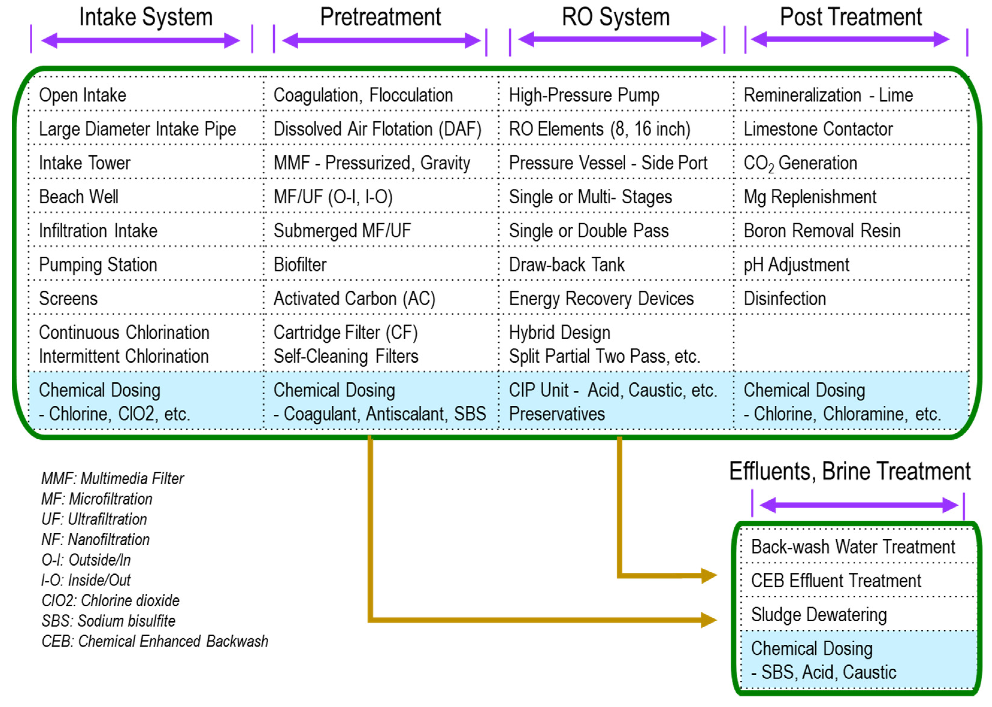
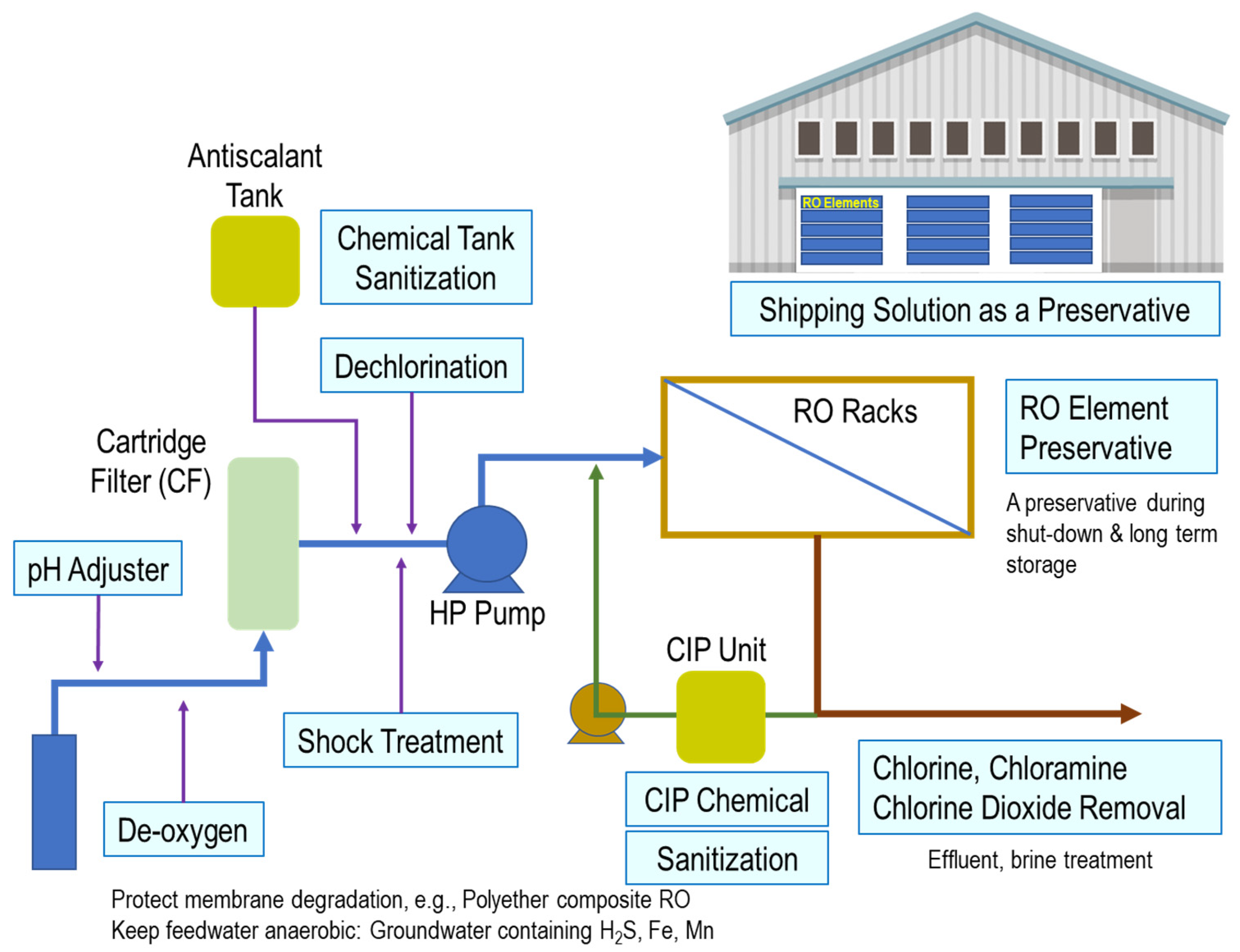
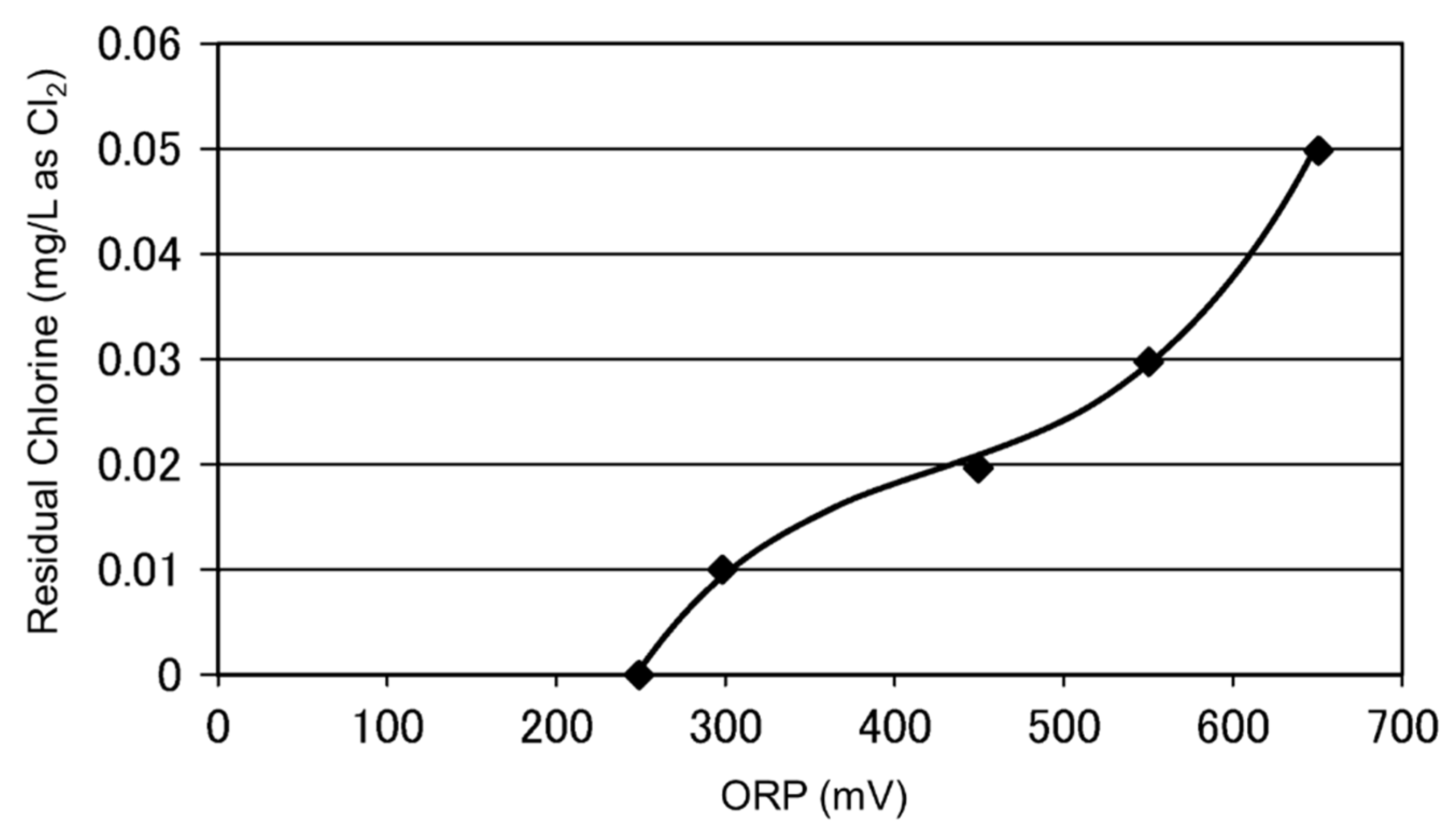
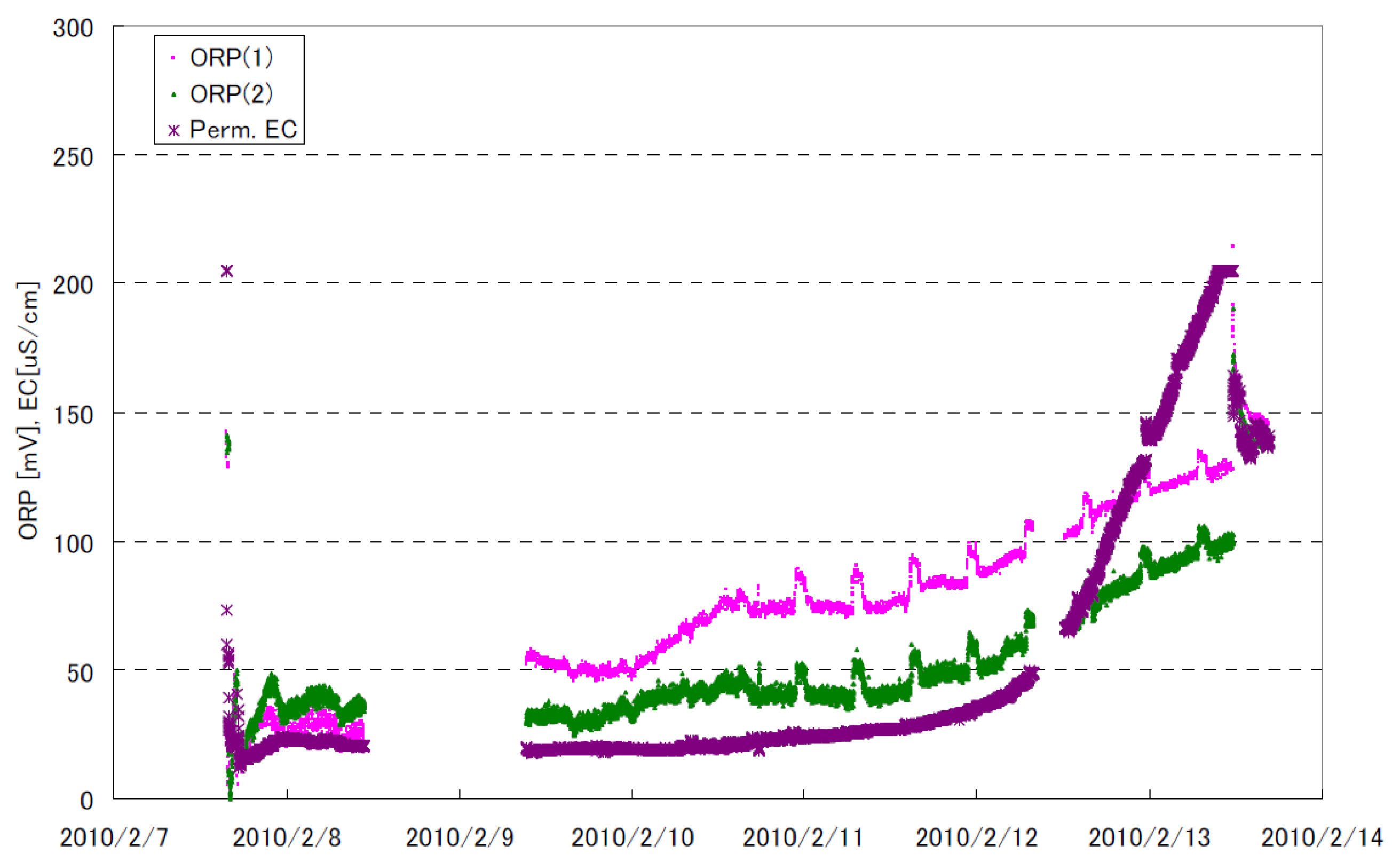
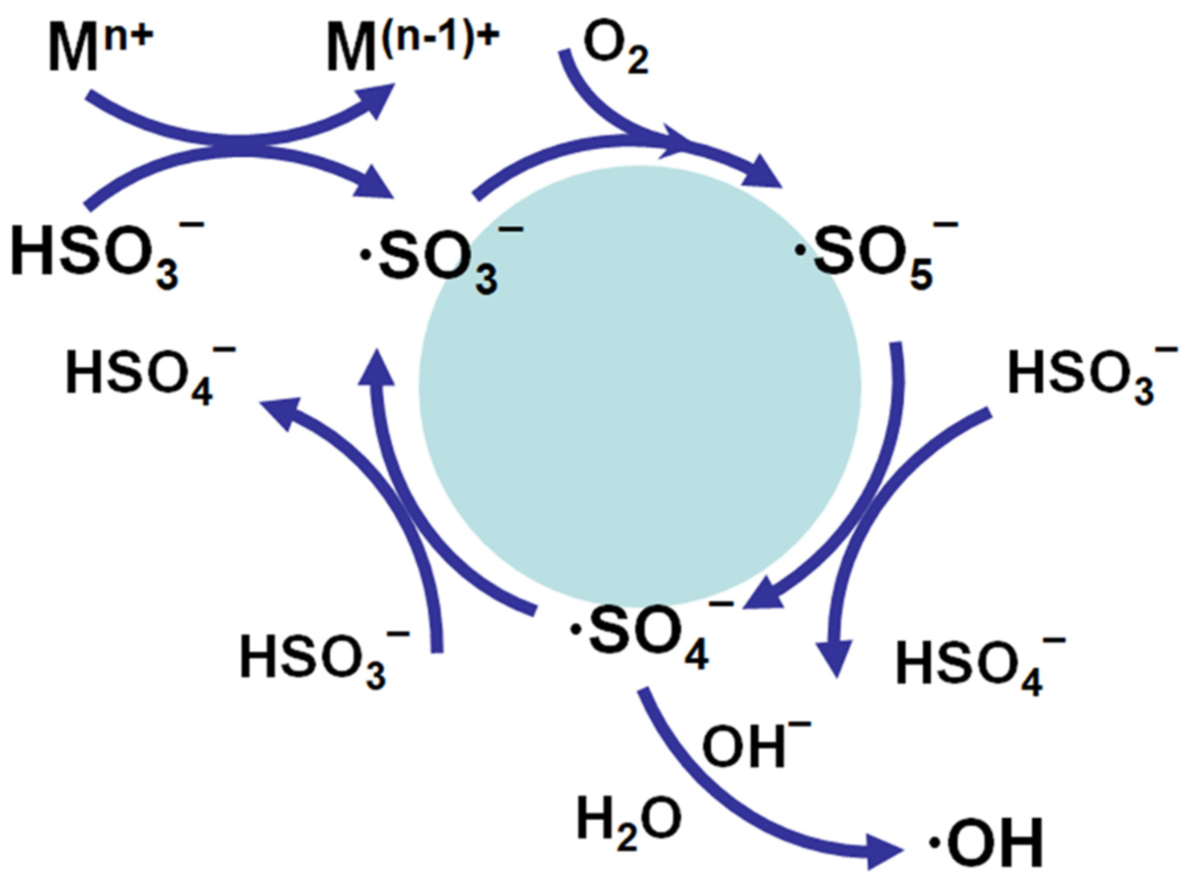
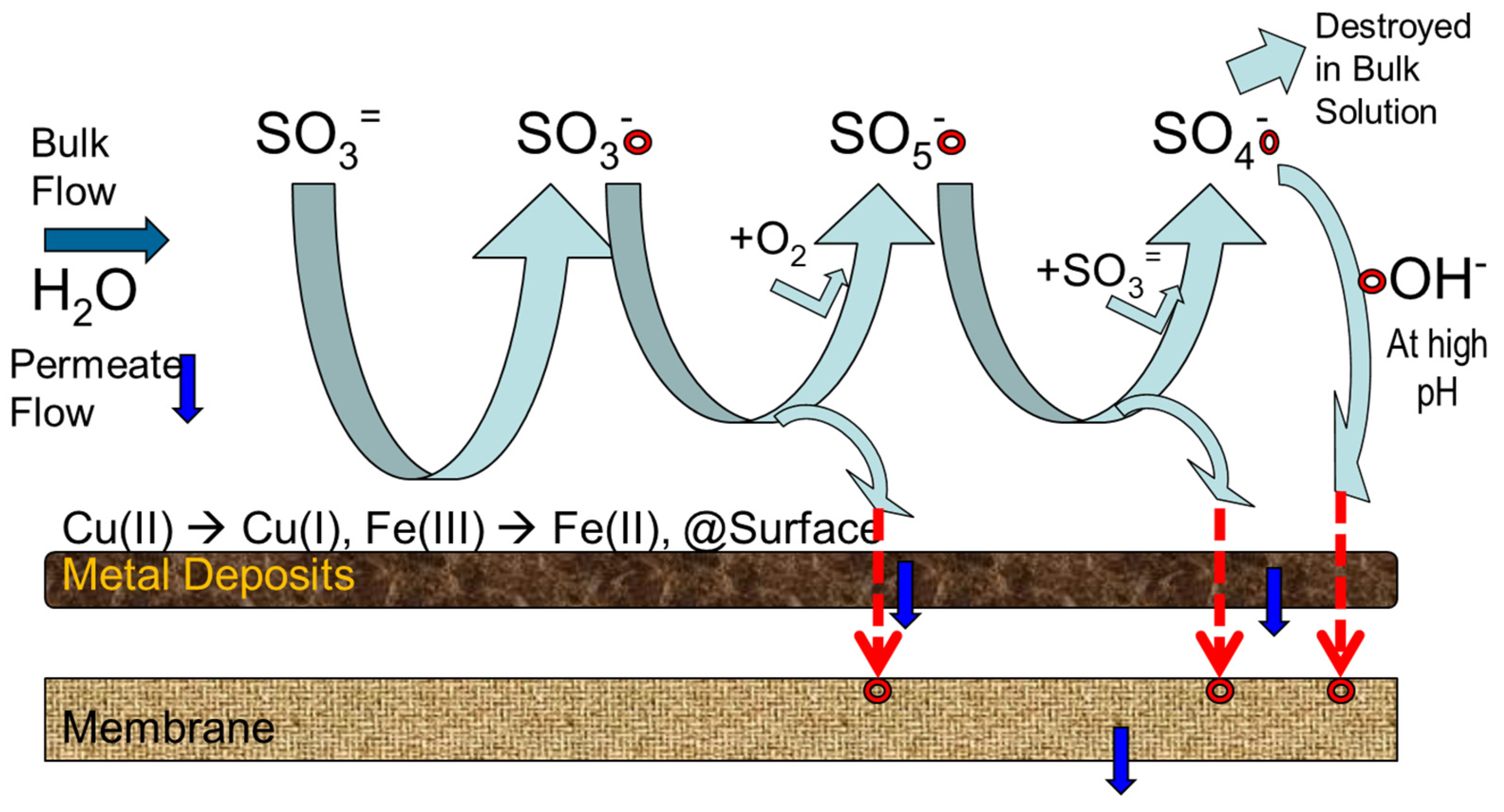
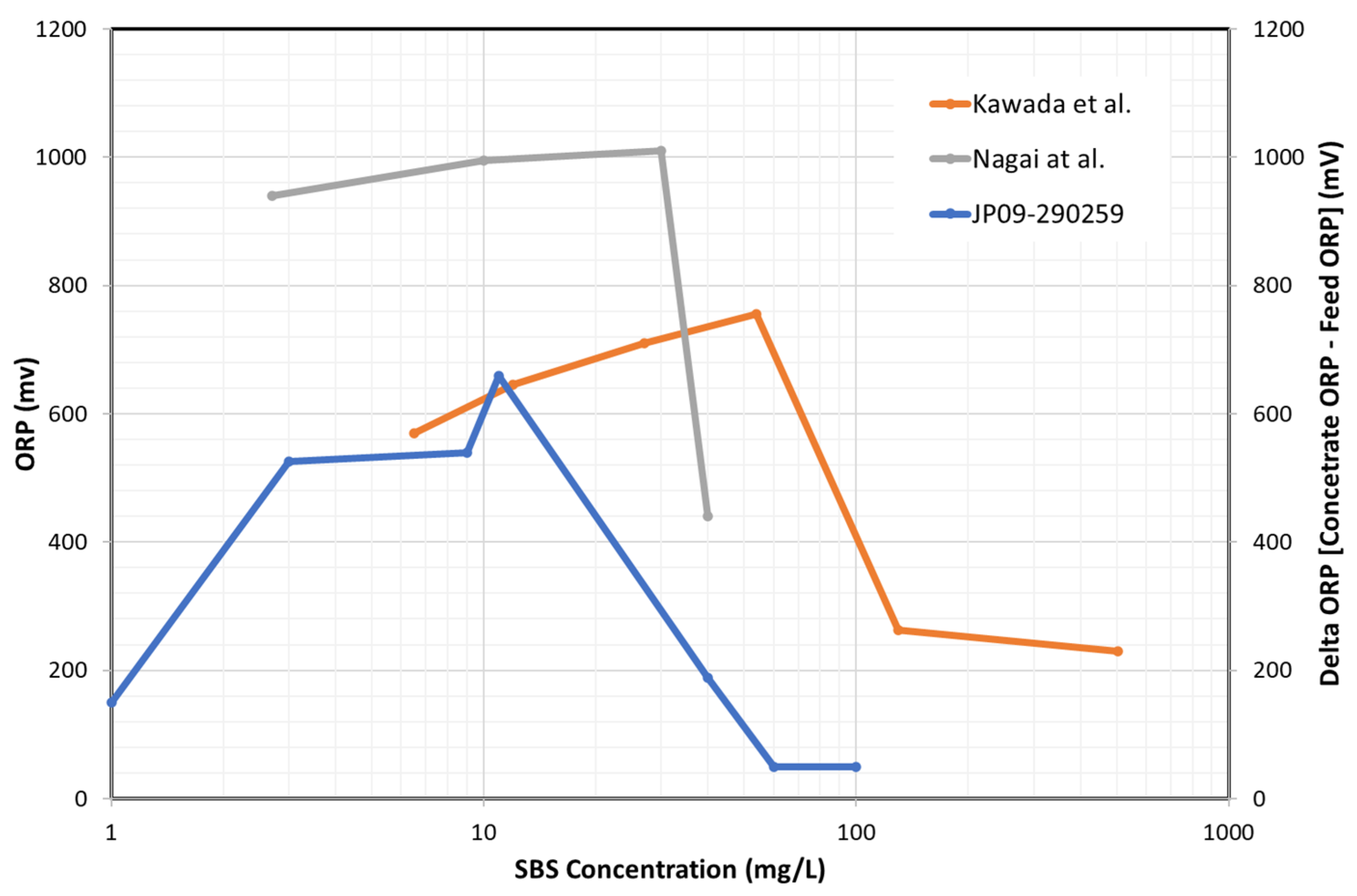
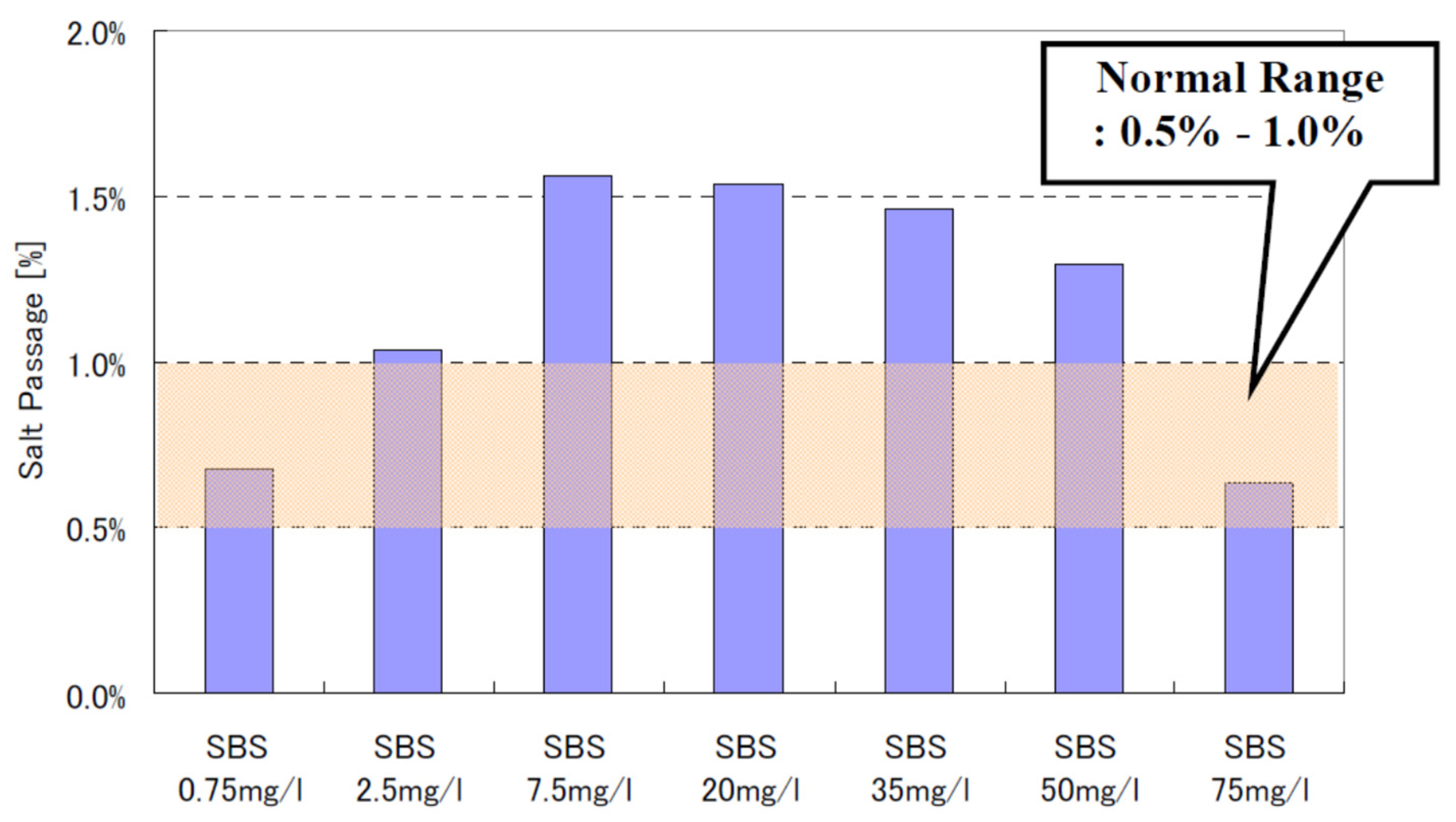
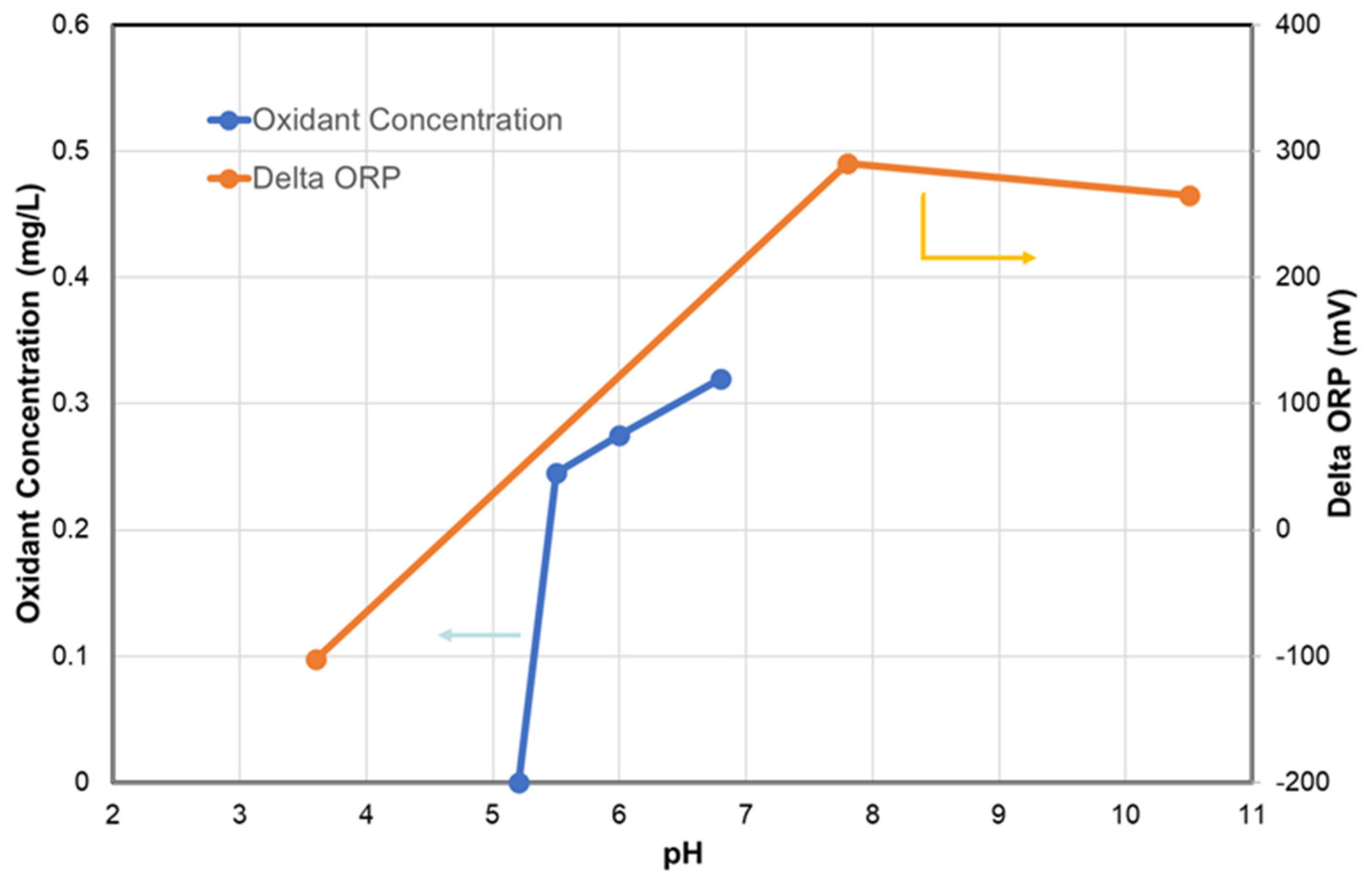
Figure 7.
Proposed radical side-stream that arrives at RO membrane surface [255].
Figure 7.
Proposed radical side-stream that arrives at RO membrane surface [255].

Figure 8.
ORP as a function of dosing SBS concentration. Kawada et al. [309]: 3.5% NaCl + 146 ppm NaHCO3 + 400 ppb Cu2+. Nagai et al. [248]: Seawater + 100 ppb Cu2+, temperature 32 °C and pH 6.5. JP09-290259 [257]: Seawater + 1.7 ppb Cu2+ (RO concentrate).

Figure 9.
Effect of SBS concentration on salt passage of BWRO membrane [255].
Figure 9.
Effect of SBS concentration on salt passage of BWRO membrane [255].

Figure 10.
ORP changes and oxidant concentration as a function of pH [114,309]. Oxidant concentration [114]: RO brine water + 0.1 ppm ClO2 + chlorite 0.64 ppm + 10 ppm SBS. Delta ORP [309]: 3.5% NaCl + 146 ppm NaHCO3 + 400 ppb Cu2+ + 11 ppm SBS.

Table 1.
SBS identification and physicochemical properties.
| IUPAC Name | Sodium Hydrogen Sulfite |
|---|---|
| CAS Number | 7631-90-5 |
| Molecular Formula | NaHSO3 |
| Molar Mass | 104.06 g/mol |
| Solubility in Water | 42 wt% in water 20 °C |
| Solution Density (20 °C) | 1.304 (37 wt% aq. Solution) 1.360 (42 wt% aq. Solution) |
| Odor | A slight odor of sulfur dioxide |
| Solution (wt%) | Shelf Life |
|---|---|
| 2 | Three (3) days |
| 10 | One (1) week |
| 20 | One (1) month |
| 30 | Six (6) months |
| Sulfites | Molecular Weight | Theoretical Dosage to Remove 1 mg Chlorine (mg) |
|---|---|---|
| Sodium sulfite | 126.1 | 1.78 |
| Sodium bisulfite (SBS) | 104.1 | 1.46 |
| Sodium metabisulfite (SMBS) | 190.2 | 1.34 |
Table 4.
The suggested dosing amount of sulfites compounds for dechlorination.
| Sulfites | Dosage to Remove 1 mg Chlorine (mg) | Stochiometric Amount Ratio | Comments | Reference |
|---|---|---|---|---|
| SMBS | 3 >3 | 2.24 >2.24 | Brackish water Seawater | [23] |
| 3 | 2.24 | [41,42] | ||
| 2 | 1.49 | [24] | ||
| SBS | 3–5 | Aramid polyamide | [43] | |
| >2 | [44] | |||
| 2 | 1.37 | [45] |
Table 5.
The reported threshold ORP values to avoid membrane oxidation.
| Membrane Manufacturer | High Alarm H (mV) | High-High Alarm HH (mV) | Reference |
|---|---|---|---|
| A | - | 175–200 | [68] |
| B | 300 | 350 | [69] |
| C | 250 | 300 | [70] |
| D | 270 (at pH = 6.0) | [71] | |
| 200 (at pH = 8.0) |
Table 6.
Disinfectants removal needs in RO process.
| Disinfectant | Redox Potential (V) | Feed | Permeate | Concentrate | Discharge from CIP Sanitization |
|---|---|---|---|---|---|
| Chloramine | 0.75 | ✓ | — | ✓ | — |
| Chlorine dioxide | 0.95 | ✓ | In case | ✓ | — |
| DBNPA | ─ | — | NA | ✓ | ✓ |
Note: In the case of ClO2, chlorite and chlorate may have to be removed.
Table 7.
Three scenarios of bromamine formation in seawater.
| Scenario | Related Key Reactions | Formed Chloramines Bromamines |
|---|---|---|
| Prechloirnated SW + NH4 salts injection | BrȒ + HOCl → Cl− + HOBr NH3 + HOBr → NH2Br + H2O NH2Br + HOBr → NHBr2 + H2O | Monobromamine Dibromamine |
| NH4 salts first or NH4 salts and NaOCl injection to SW together | NH3 + HOCl → NH2Cl + H2O | Monochloramine |
| NH2Cl + HOCl → NHCl2 + H2O | Dichloramine | |
| NH3 + HOBr → NH2Br + H2O | Bromamine | |
| NH2Br + HOBr → NHBr2 + H2O | Dibromamine | |
| Preformed chloramine injection to SW | NH2Cl (stable for an hour in SW) | Monochloramine |
| NH2Cl + Br− + H+ → NHBrCl + NH4 + Cl− | Bromochloramine |
Table 8.
Theoretical sulfites and thiosulfate dosages for chlorine dioxide removal.
| Sulfites | Molecular Weight | Theoretical Dosage to Remove 1 mg ClO2 (mg) |
|---|---|---|
| Sodium sulfite | 126.1 | 4.67 |
| SBS | 104.1 | 3.85 |
| SMBS | 190.2 | 3.52 |
| Sodium thiosulfate | 158.11 | 1.46 |
Table 9.
Oxidation potential for relevant oxidants.
| Chemical Species | Standard Oxidation Potential (V) | Relative Strength |
|---|---|---|
| Hydroxy radical (∙OH) | 2.8 | 2.0 |
| Sulfate radical (∙SO4−) | 2.6 | 1.8 |
| Ozone (O3) | 2.1 | 1.5 |
| Persulfate Anion (S2O82−) | 2.0 | 1.4 |
| Peroxymonosulfate (HSO5−) [307] | 1.8 | 1.3 |
| Chlorine (Cl2) | 1.4 | 1.0 |
| Peroxymonosulfate radical (∙SO5−) at pH 7.0 [308] | 1.1 | 0.8 |
| Sulfite radical (∙SO3−) at pH > 7.0 [308] | 0.63 | 0.5 |
Table 10.
Factors affecting membrane degradation by SBS.
| Factors Affecting Membrane Degradation by SBS | References |
|---|---|
| Heavy metals | [47,248,252,309] |
| SBS concentration | [248,309] |
| Dissolved oxygen concentration | [248] |
| Feed pH | [47,197,309] |
| Bicarbonate ion concentration | [47,197,309] |
| Chloride ion concentration | [248] |
| Salinity or feed TDS | [47,197] |
| Temperature | [47,197] |
Table 13.
Effect of chelating agents for SWRO membrane performance [184].
Table 13.
Effect of chelating agents for SWRO membrane performance [184].
| Chelating Agent | Initial | 100 h | 1000 h | |||
|---|---|---|---|---|---|---|
| SP (%) | Flux (m/d) | SP (%) | Flux (m/d) | SP (%) | Flux (m/d) | |
| None | 0.52 | 0.68 | 0.78 | 0.69 | 1.60 | 0.81 |
| SHMP 10 ppm | 0.50 | 0.67 | 0.49 | 0.66 | 0.53 | 0.65 |
| EDTA 5 ppm | 0.49 | 0.69 | 0.51 | 0.68 | 0.54 | 0.65 |
Feed: 3.5% NaCl solution containing 10 ppb of Cu and 20 ppm of SBS. Test conditions (pressure): 56 kg/cm2. Flux (m/d): m3/m2/day.
Publisher’s Note: MDPI stays neutral with regard to jurisdictional claims in published maps and institutional affiliations. |
© 2022 by the author. Licensee MDPI, Basel, Switzerland. This article is an open access article distributed under the terms and conditions of the Creative Commons Attribution (CC BY) license (https://creativecommons.org/licenses/by/4.0/).
Share and Cite
MDPI and ACS Style
Maeda, Y. Roles of Sulfites in Reverse Osmosis (RO) Plants and Adverse Effects in RO Operation. Membranes 2022, 12, 170. https://doi.org/10.3390/membranes12020170
AMA Style
Maeda Y. Roles of Sulfites in Reverse Osmosis (RO) Plants and Adverse Effects in RO Operation. Membranes. 2022; 12(2):170. https://doi.org/10.3390/membranes12020170
Chicago/Turabian StyleMaeda, Yasushi. 2022. "Roles of Sulfites in Reverse Osmosis (RO) Plants and Adverse Effects in RO Operation" Membranes 12, no. 2: 170. https://doi.org/10.3390/membranes12020170
Note that from the first issue of 2016, this journal uses article numbers instead of page numbers. See further details here.