
Polymers and Solvents Used in Membrane Fabrication: A Review Focusing on Sustainable Membrane Development


Abstract
:
1. Introduction
2. Membrane Fabrication
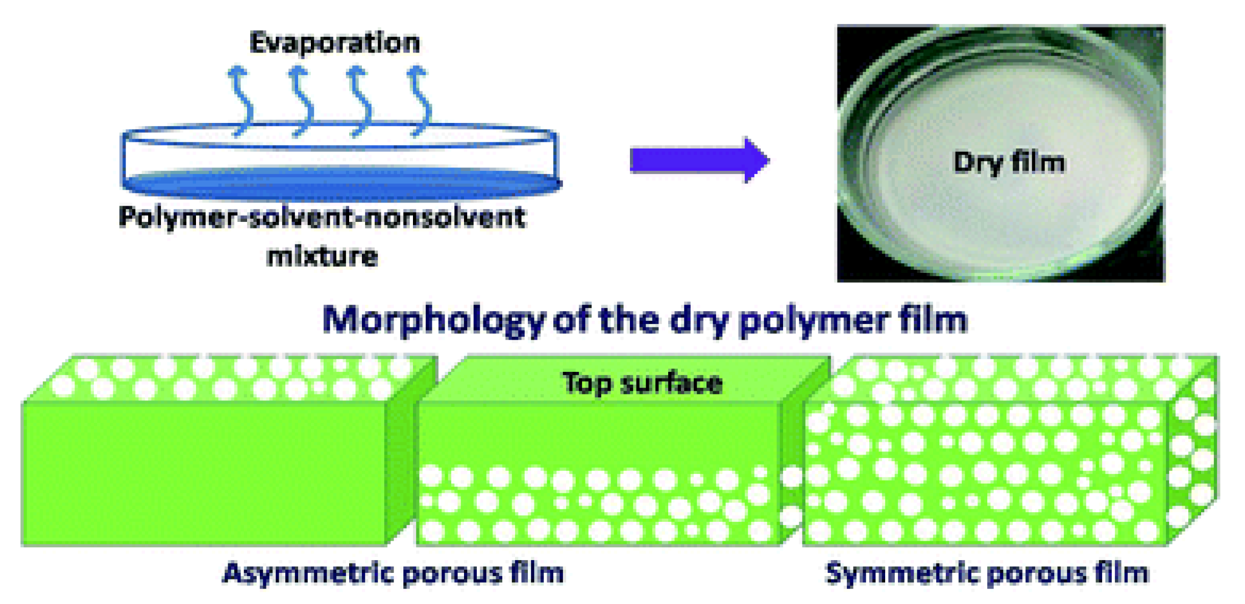
2.1. Fabrication Methods
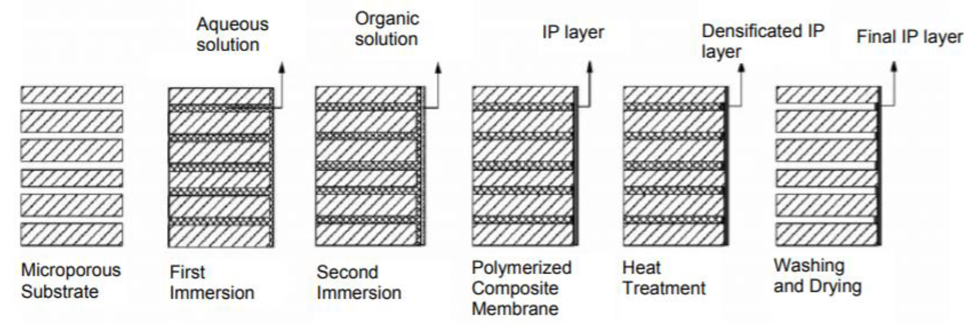
2.1.1. Interfacial Polymerization
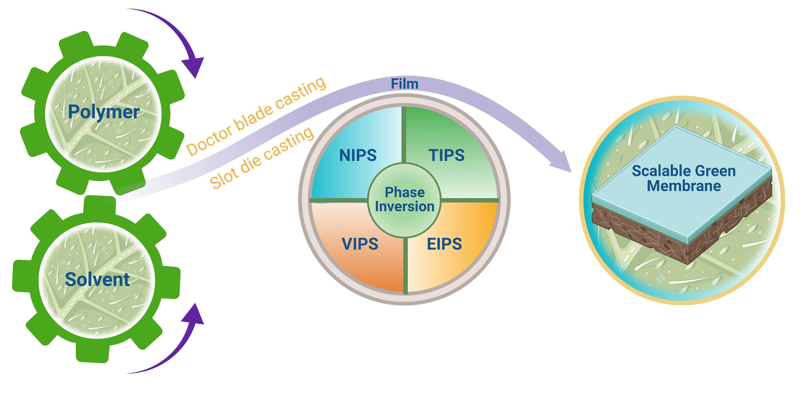
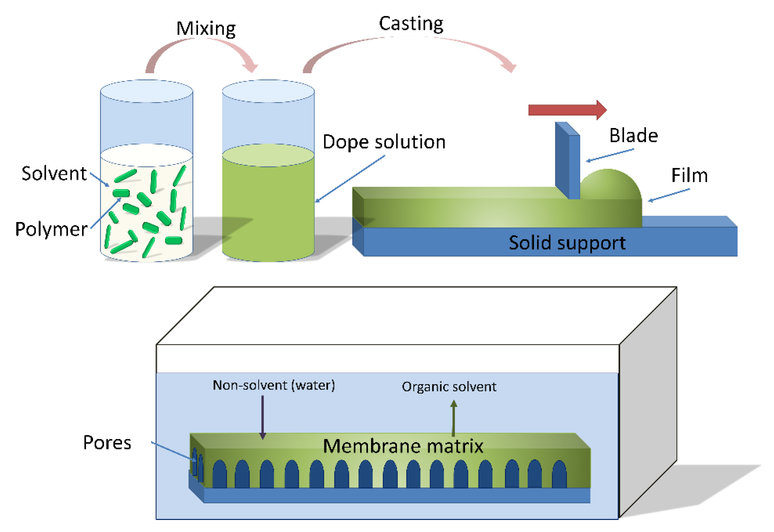
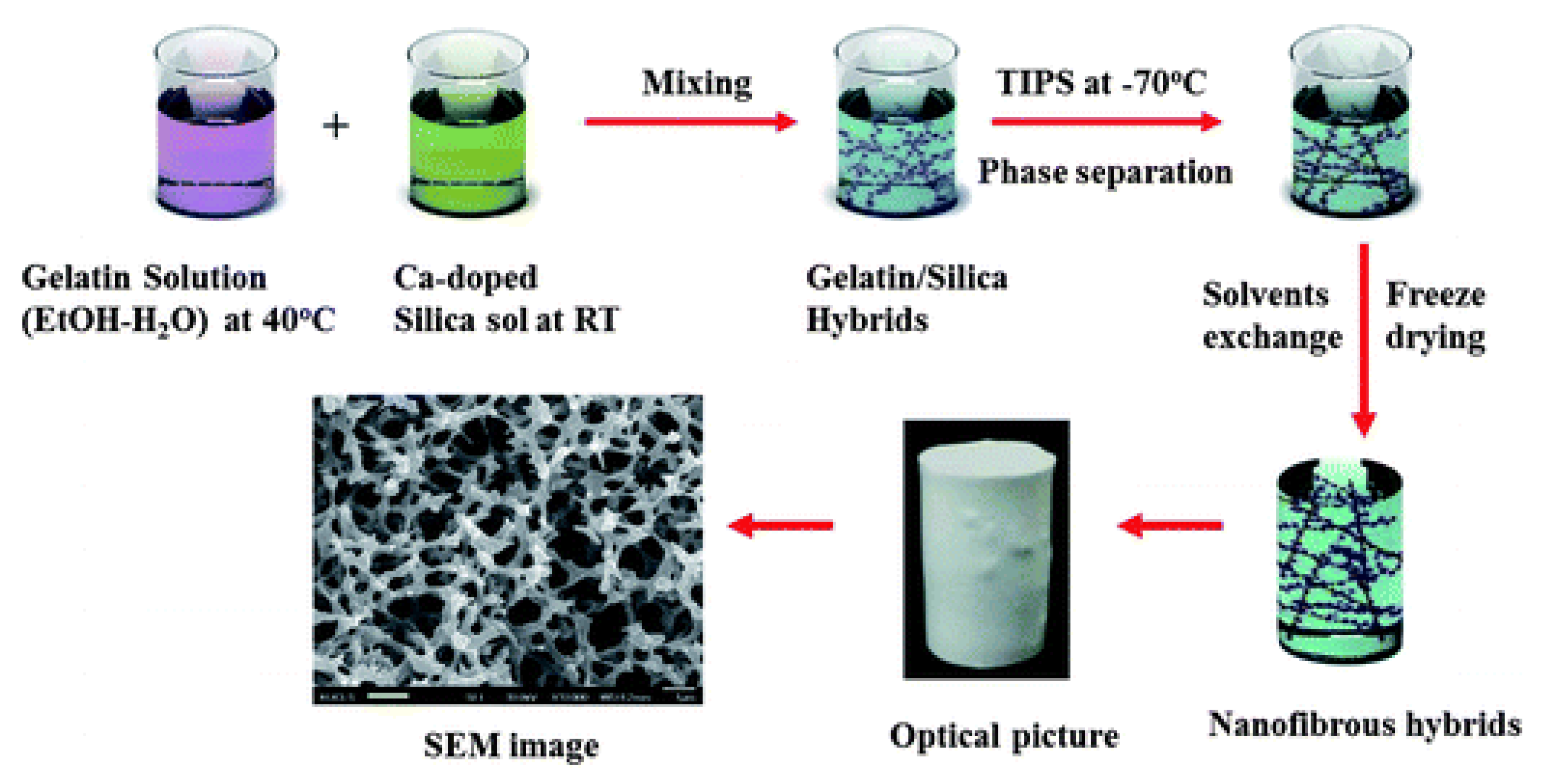
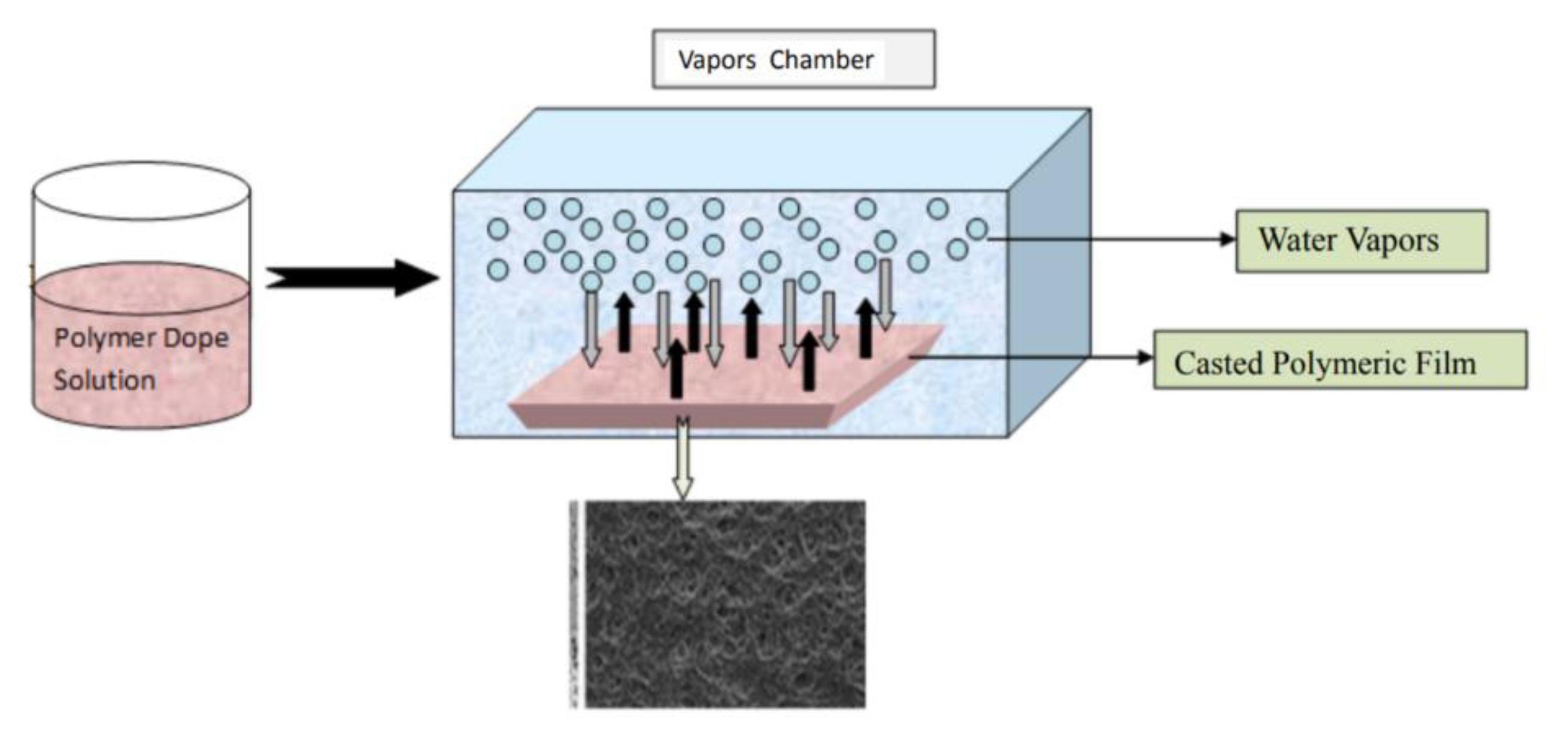
2.1.2. Phase Separation Methods
2.2. NIPS Materials
2.2.1. Polymers
2.2.2. Solvents
Methyl Lactate
Triethylphosphate
Ionic Liquids
Organic Carbonates
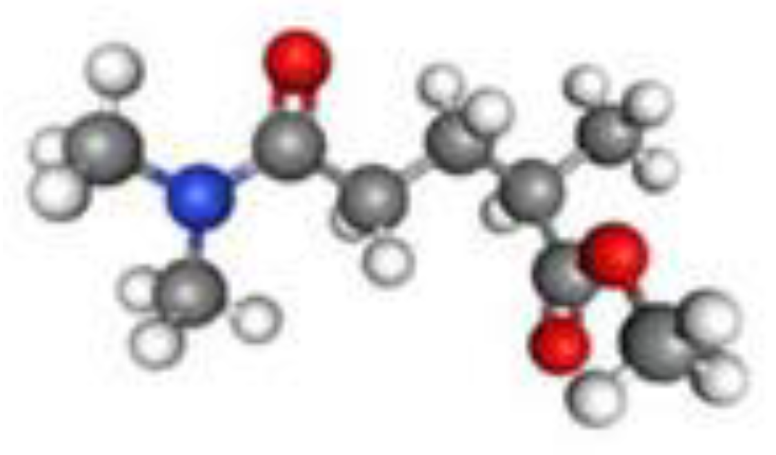
Rhodiasolv® PolarClean
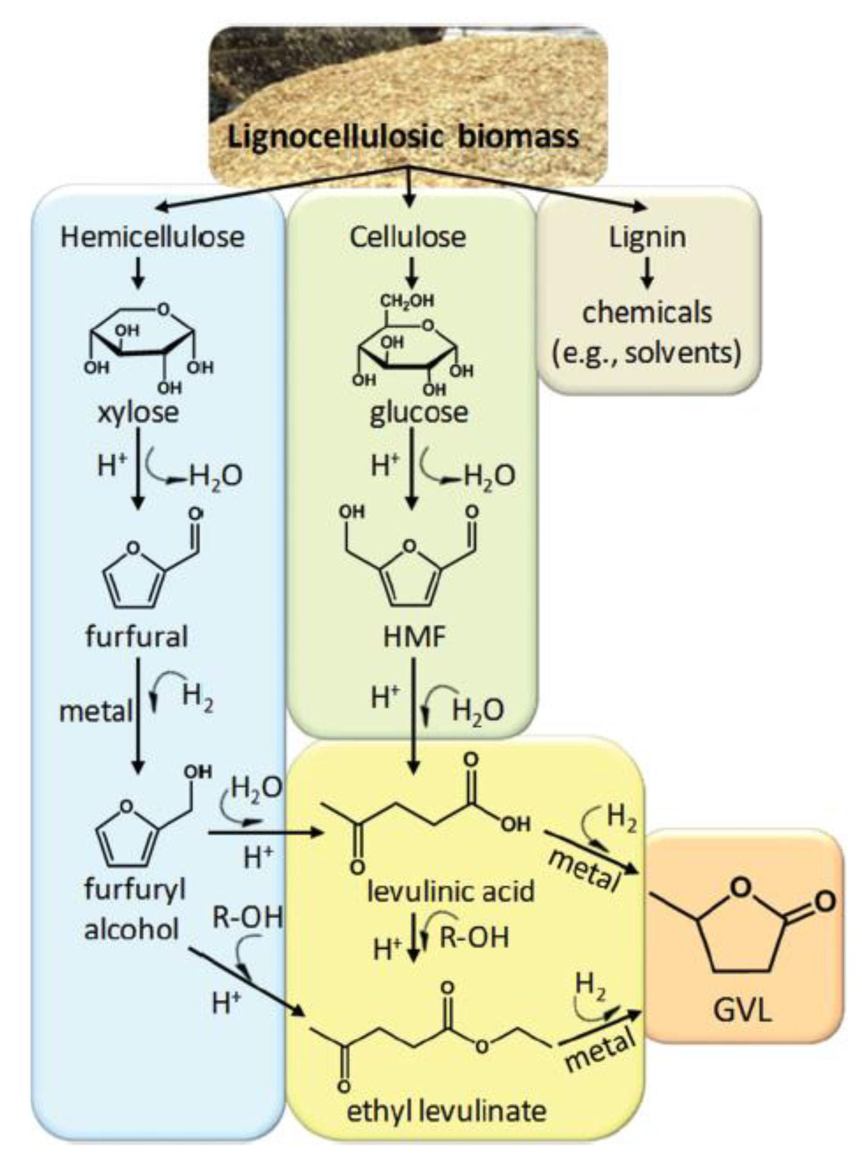
Gamma-Valerolactone
PolarClean and GVL as Co-Solvents
2.3. Influencing Factors on Membrane Morphology
3. Measures of System Compatibility
3.1. Hansen Solubility Parameter
3.2. Viscosity of the Dope Solution
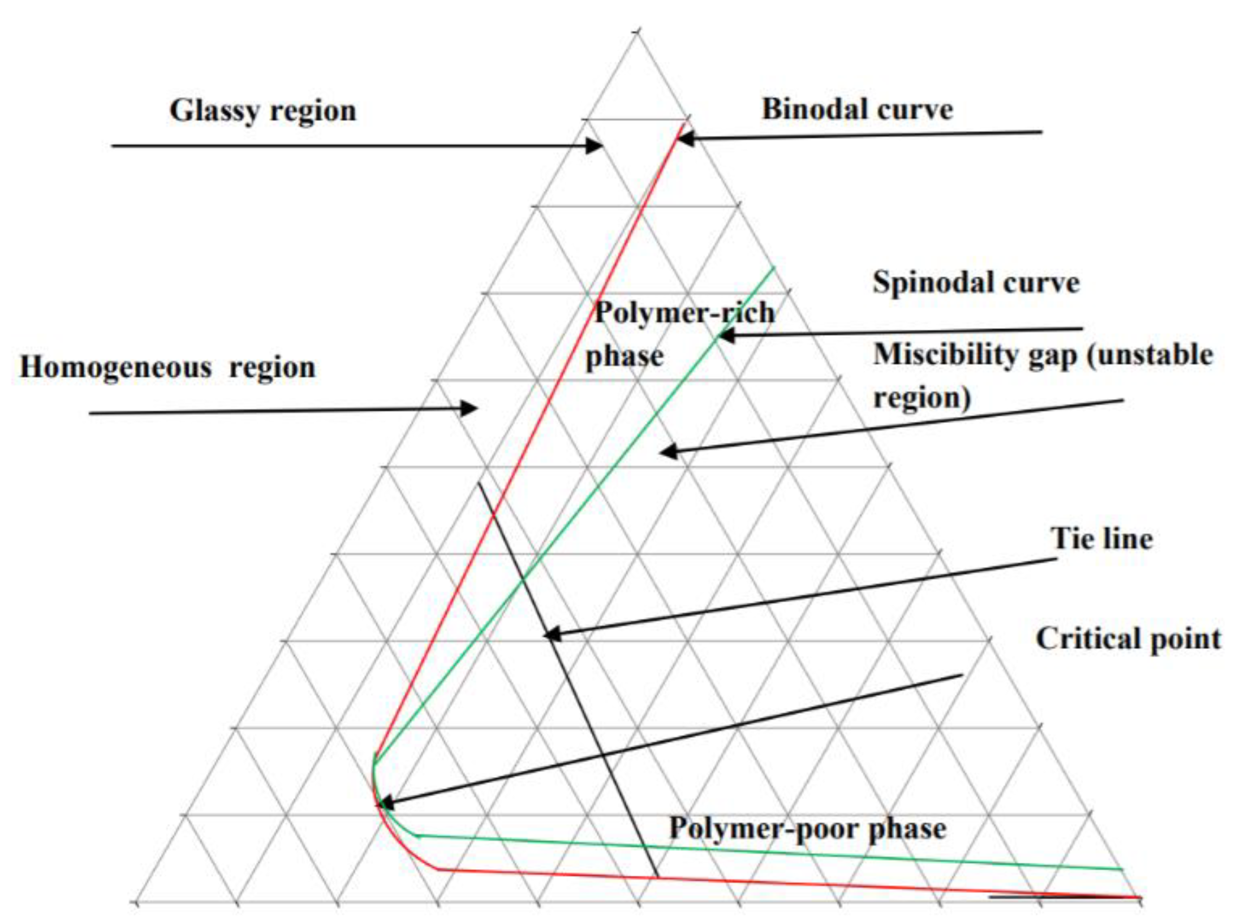
3.3. Ternary Phase Diagram
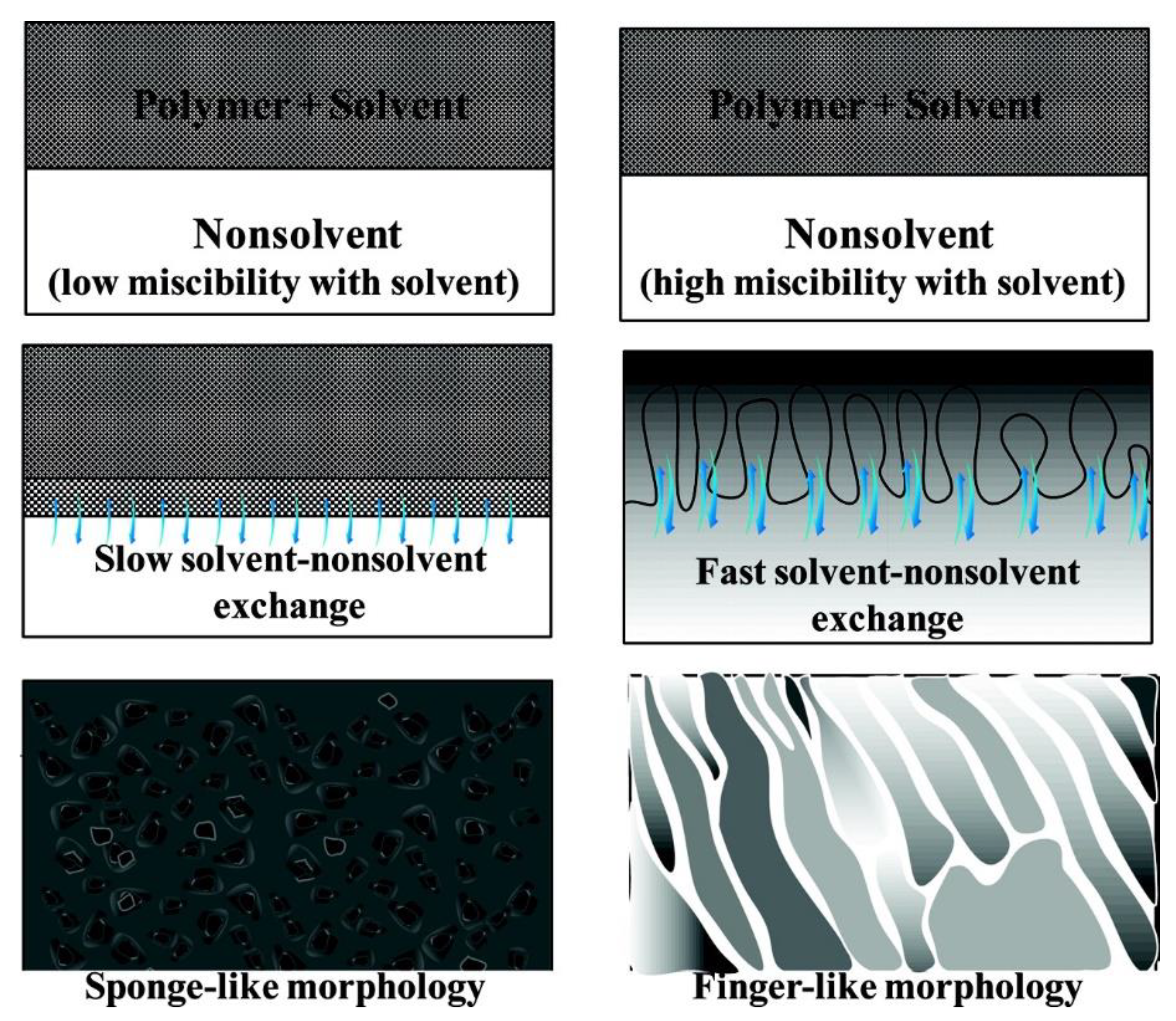
3.4. Diffusion Rate of Solvent and Non-Solvent
3.5. Case Study
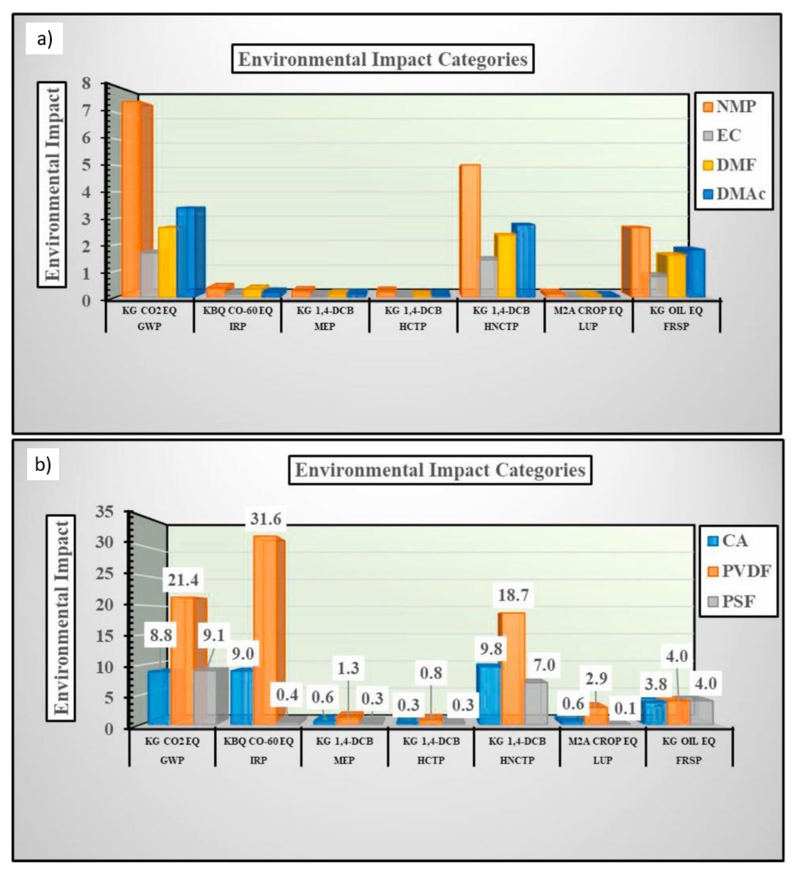
4. Evaluation of Membrane Sustainability
5. Scaling Up the Fabrication Process Using Green Solvents
5.1. Scale Up of the Membrane Fabrication Process
5.2. Comparison of Doctor Blade Casting and Slot Die Casting of Membranes
5.3. Advantage of Slot Die Casting for Scale Up
5.4. Case Study of Scale Up
6. Conclusions and Perspectives
Author Contributions
Funding
Institutional Review Board Statement
Informed Consent Statement
Data Availability Statement
Conflicts of Interest
References
- Figoli, A.; Marino, T.; Simone, S.; Di Nicolò, E.; Li, X.-M.; He, T.; Tornaghi, S.; Drioli, E. Towards non-toxic solvents for membrane preparation: A review. Green Chem. 2014, 16, 4034–4059. [Google Scholar] [CrossRef]
- Clark, J.H.; Tavener, S.J. Alternative Solvents: Shades of Green. Org. Process. Res. Dev. 2007, 11, 149–155. [Google Scholar] [CrossRef]
- Jessop, P.G. Searching for green solvents. Green Chem. 2011, 13, 1391–1398. [Google Scholar] [CrossRef]
- Capello, C.; Fischer, U.; Hungerbühler, K. What is a green solvent? A comprehensive framework for the environmental assessment of solvents. Green Chem. 2007, 9, 927–934. [Google Scholar]
- Clark, J.H.; Farmer, T.J.; Hunt, A.J.; Sherwood, J. Opportunities for Bio-Based Solvents Created as Petrochemical and Fuel Products Transition towards Renewable Resources. Int. J. Mol. Sci. 2015, 16, 17101–17159. [Google Scholar] [CrossRef]
- Gu, Y.; Jérôme, F. Bio-based solvents: An emerging generation of fluids for the design of eco-efficient processes in catalysis and organic chemistry. Chem. Soc. Rev. 2013, 42, 9550–9570. [Google Scholar] [CrossRef] [PubMed]
- Nie, L.; Chuah, C.Y.; Bae, T.; Lee, J. Graphene-Based Advanced Membrane Applications in Organic Solvent Nanofiltration. Adv. Funct. Mater. 2021, 31, 2006949. [Google Scholar] [CrossRef]
- Lau, W.J.; Ismail, A.F. Progress in interfacial polymerization technique on composite membrane preparation. In Proceedings of the 2011 2nd International Conference on Environmental Engineering and Applications (ICEEA 2011), Shanghai, China, 19–21 August 2011. [Google Scholar]
- Wong, C.Y.; Wong, W.Y.; Loh, K.S.; Daud, W.R.W.; Lim, K.L.; Khalid, M.; Walvekar, R. Development of Poly(Vinyl Alcohol)-Based Polymers as Proton Exchange Membranes and Challenges in Fuel Cell Application: A Review. Polym. Rev. 2020, 60, 171–202. [Google Scholar] [CrossRef]
- Rosli, N.A.H.; Loh, K.S.; Wong, W.Y.; Yunus, R.M.; Lee, T.K.; Ahmad, A.; Chong, S.T. Review of Chitosan-Based Polymers as Proton Exchange Membranes and Roles of Chitosan-Supported Ionic Liquids. Int. J. Mol. Sci. 2020, 21, 632. [Google Scholar] [CrossRef] [Green Version]
- Chen, M.; Zhu, L.; Chen, J.; Yang, F.; Tang, C.Y.; Guiver, M.D.; Dong, Y. Spinel-based ceramic membranes coupling solid sludge recycling with oily wastewater treatment. Water Res. 2020, 169, 115180. [Google Scholar] [CrossRef]
- Gao, N.; Fan, W.; Xu, Z.-K. Ceramic membrane with protein-resistant surface via dopamine/diglycolamine co-deposition. Sep. Purif. Technol. 2020, 234, 116135. [Google Scholar] [CrossRef]
- Chong, J.Y.; Wang, B.; Li, K. High performance stainless steel-ceramic composite hollow fibres for microfiltration. J. Membr. Sci. 2017, 541, 425–433. [Google Scholar] [CrossRef]
- Gao, X.; Gao, B.; Liu, H.; Zhang, C.; Zhang, Y.; Jiang, J.; Gu, X. Fabrication of stainless steel hollow fiber supported NaA zeolite membrane by self-assembly of submicron seeds. Sep. Purif. Technol. 2020, 234, 116121. [Google Scholar] [CrossRef]
- Filippov, A.; Petrova, D.; Falina, I.; Kononenko, N.; Ivanov, E.; Lvov, Y.; Vinokurov, V. Transport asymmetry of novel bi-layer hybrid perfluorinated membranes on the base of mf-4sc modified by halloysite nanotubes with platinum. Polymers 2018, 10, 366. [Google Scholar] [CrossRef] [Green Version]
- Guillen, G.R.; Pan, Y.; Li, M.; Hoek, E.M.V. Preparation and Characterization of Membranes Formed by Nonsolvent Induced Phase Separation: A Review. Ind. Eng. Chem. Res. 2011, 50, 3798–3817. [Google Scholar] [CrossRef]
- Hausman, R.; Digman, B.; Escobar, I.C.; Coleman, M.; Chung, T.-S.; Chung, N.T.-S. Functionalization of polybenzimidizole membranes to impart negative charge and hydrophilicity. J. Membr. Sci. 2010, 363, 195–203. [Google Scholar] [CrossRef]
- Staiti, P.; Lufrano, F.; Aricò, A.; Passalacqua, E.; Antonucci, V. Sulfonated polybenzimidazole membranes—Preparation and physico-chemical characterization. J. Membr. Sci. 2001, 188, 71–78. [Google Scholar] [CrossRef]
- Kim, J.; van der Bruggen, B. The use of nanoparticles in polymeric and ceramic membrane structures: Review of manufacturing procedures and performance improvement for water treatment. Environ. Pollut. 2010, 158, 2335–2349. [Google Scholar] [CrossRef]
- Mallevialle, J.; Bersillon, J.L.; Anselme, C.; Aptel, P. Membrane Filtration in drinking-water treatment—A case story. In Influence and Removal of Organics in Drinking Water; Mallevialle, J., Suffet, I.H., Chan, U.S., Eds.; CRC Press: Boca Raton, FL, USA, 1992; pp. 299–310. [Google Scholar]
- Pagliero, M.; Bottino, A.; Comite, A.; Costa, C. Novel hydrophobic PVDF membranes prepared by nonsolvent induced phase separation for membrane distillation. J. Membr. Sci. 2020, 596, 117575. [Google Scholar] [CrossRef]
- Dong, X.; Al-Jumaily, A.; Escobar, I.C. Investigation of the Use of a Bio-Derived Solvent for Non-Solvent-Induced Phase Separation (NIPS) Fabrication of Polysulfone Membranes. Membranes 2018, 8, 23. [Google Scholar] [CrossRef] [Green Version]
- M’Barki, O.; Hanafia, A.; Bouyer, D.; Faur, C.; Sescousse, R.; Delabre, U.; Blot, C.; Guenoun, P.; Deratani, A.; Quemener, D.; et al. Greener method to prepare porous polymer membranes by combining thermally induced phase separation and crosslinking of poly(vinyl alcohol) in water. J. Membr. Sci. 2014, 458, 225–235. [Google Scholar] [CrossRef]
- Lei, B.; Shin, K.-H.; Noh, D.-Y.; Jo, I.-H.; Koh, Y.-H.; Choi, W.-Y.; Kim, H.-E. Nanofibrous gelatin—Silica hybrid scaffolds mimicking the native extracellular matrix (ECM) using thermally induced phase separation. J. Mater. Chem. 2012, 22, 14133–14140. [Google Scholar] [CrossRef]
- Zahid, M.; Rashid, A.; Akram, S.; Rehan, Z.A.; Razzaq, W. A Comprehensive Review on Polymeric Nano-Composite Membranes for Water Treatment. J. Membr. Sci. Technol. 2018, 8, 1–20. [Google Scholar] [CrossRef]
- Zhao, Q.; Xie, R.; Luo, F.; Faraj, Y.; Liu, Z.; Ju, X.-J.; Wang, W.; Chu, L.-Y. Preparation of high strength poly(vinylidene fluoride) porous membranes with cellular structure via vapor-induced phase separation. J. Membr. Sci. 2018, 549, 151–164. [Google Scholar] [CrossRef]
- Pervin, R.; Ghosh, P.; Basavaraj, M.G. Tailoring pore distribution in polymer films via evaporation induced phase separation. RSC Adv. 2019, 9, 15593–15605. [Google Scholar] [CrossRef] [Green Version]
- Samuel, A.Z.; Umapathy, S.; Ramakrishnan, S. Functionalized and Postfunctionalizable Porous Polymeric Films through Evaporation-Induced Phase Separation Using Mixed Solvents. ACS Appl. Mater. Interfaces 2011, 3, 3293–3299. [Google Scholar] [CrossRef]
- Ismail, N.; Venault, A.; Mikkola, J.-P.; Bouyer, D.; Drioli, E.; Kiadeh, N.T.H. Investigating the potential of membranes formed by the vapor induced phase separation process. J. Membr. Sci. 2020, 597, 117601. [Google Scholar] [CrossRef]
- Lu, W.; Yuan, Z.; Zhao, Y.; Zhang, H.; Zhang, H.; Li, X. Porous membranes in secondary battery technologies. Chem. Soc. Rev. 2017, 46, 2199–2236. [Google Scholar] [CrossRef]
- Kim, J.F.; Kim, J.H.; Lee, Y.M.; Drioli, E. Thermally induced phase separation and electrospinning methods for emerging membrane applications: A review. AIChE J. 2016, 62, 461–490. [Google Scholar] [CrossRef]
- Khare, V.P.; Greenberg, A.R.; Krantz, W.B. Vapor-induced phase separation—Effect of the humid air exposure step on membrane morphology: Part I. Insights from mathematical modeling. J. Membr. Sci. 2005, 258, 140–156. [Google Scholar] [CrossRef]
- Chen, Z.; Deng, M.; Chen, Y.; He, G.; Wu, M.; Wang, J. Preparation and performance of cellulose acetate/polyethyleneimine blend microfiltration membranes and their applications. J. Membr. Sci. 2004, 235, 73–86. [Google Scholar] [CrossRef]
- Sivakumar, M.; Mohan, D.R.; Rangarajan, R. Studies on cellulose acetate-polysulfone ultrafiltration membranes: II. Effect of additive concentration. J. Membr. Sci. 2006, 268, 208–219. [Google Scholar] [CrossRef]
- Kutowy, O.; Sourirajan, S. Cellulose acetate ultrafiltration membranes. J. Appl. Polym. Sci. 1975, 19, 1449–1460. [Google Scholar] [CrossRef]
- Haddada, R.; Ferjani, E.; Roudesli, M.S.; Deratani, A. Properties of cellulose acetate nanofiltration membranes. Application to brackish water desalination. Desalination 2004, 167, 403–409. [Google Scholar] [CrossRef]
- Duarte, A.P.; Cidade, M.T.; Bordado, J.C. Cellulose acetate reverse osmosis membranes: Optimization of the composition. J. Appl. Polym. Sci. 2006, 100, 4052–4058. [Google Scholar] [CrossRef]
- Idris, A.; Yet, L.K. The effect of different molecular weight PEG additives on cellulose acetate asymmetric dialysis membrane performance. J. Membr. Sci. 2006, 280, 920–927. [Google Scholar] [CrossRef]
- Zhao, C.; Xue, J.; Ran, F.; Sun, S. Modification of polyethersulfone membranes—A review of methods. Prog. Mater. Sci. 2013, 58, 76–150. [Google Scholar] [CrossRef]
- Otitoju, T.A.; Ahmad, A.L.; Ooi, B.S. Recent advances in hydrophilic modification and performance of polyethersulfone (PES) membrane via additive blending. RSC Adv. 2018, 8, 22710–22728. [Google Scholar] [CrossRef] [Green Version]
- van der Bruggen, B. Chemical modification of polyethersulfone nanofiltration membranes: A review. J. Appl. Polym. Sci. 2009, 114, 630–642. [Google Scholar] [CrossRef]
- Liu, F.; Hashim, N.A.; Liu, Y.; Abed, M.M.; Li, K. Progress in the production and modification of PVDF membranes. J. Membr. Sci. 2011, 375, 1–27. [Google Scholar] [CrossRef]
- Eykens, L.; de Sitter, K.; Dotremont, C.; Pinoy, L.; van der Bruggen, B. Membrane synthesis for membrane distillation: A review. Sep. Purif. Technol. 2017, 182, 36–51. [Google Scholar] [CrossRef]
- Alkhudhiri, A.; Darwish, N.; Hilal, N. Membrane distillation: A comprehensive review. Desalination 2012, 287, 2–18. [Google Scholar] [CrossRef]
- Kang, G.-D.; Cao, Y.-M. Application and modification of poly(vinylidene fluoride) (PVDF) membranes—A review. J. Membr. Sci. 2014, 463, 145–165. [Google Scholar] [CrossRef]
- Colburn, A.; Vogler, R.J.; Patel, A.; Bezold, M.; Craven, J.; Liu, C.; Bhattacharyya, D. Composite Membranes Derived from Cellulose and Lignin Sulfonate for Selective Separations and Antifouling Aspects. Nanomaterials 2019, 9, 867. [Google Scholar] [CrossRef] [PubMed] [Green Version]
- Galiano, F.; Briceño, K.; Marino, T.; Molino, A.; Christensen, K.V.; Figoli, A. Advances in biopolymer-based membrane preparation and applications. J. Membr. Sci. 2018, 564, 562–586. [Google Scholar] [CrossRef]
- Le Phuong, H.A.; Ayob, N.A.I.; Blanford, C.F.; Rawi, N.F.M.; Szekely, G. Nonwoven Membrane Supports from Renewable Resources: Bamboo Fiber Reinforced Poly(Lactic Acid) Composites. ACS Sustain. Chem. Eng. 2019, 7, 11885–11893. [Google Scholar] [CrossRef]
- Esfahani, M.R.; Taylor, A.; Serwinowski, N.; Parkerson, Z.J.; Confer, M.P.; Kammakakam, I.; Bara, J.E.; Esfahani, A.R.; Mahmoodi, S.N.; Koutahzadeh, N.; et al. Sustainable Novel Bamboo-Based Membranes for Water Treatment Fabricated by Regeneration of Bamboo Waste Fibers. ACS Sustain. Chem. Eng. 2020, 8, 4225–4235. [Google Scholar] [CrossRef]
- Clasen, C.; Wilhelms, A.T.; Kulicke, W.-M. Formation and Characterization of Chitosan Membranes. Biomacromolecules 2006, 7, 3210–3222. [Google Scholar] [CrossRef]
- Ray, M.; Pal, K.; Anis, A.; Banthia, A.K. Development and Characterization of Chitosan-Based Polymeric Hydrogel Membranes. Des. Monomers Polym. 2010, 13, 193–206. [Google Scholar] [CrossRef] [Green Version]
- Thakur, V.K.; Voicu, S.I. Recent advances in cellulose and chitosan based membranes for water purification: A concise review. Carbohydr. Polym. 2016, 146, 148–165. [Google Scholar] [CrossRef] [PubMed]
- Gaur, S.S.; Dhar, P.; Sonowal, A.; Sharma, A.; Kumar, A.; Katiyar, V. Thermo-mechanically stable sustainable polymer based solid electrolyte membranes for direct methanol fuel cell applications. J. Membr. Sci. 2017, 526, 348–354. [Google Scholar] [CrossRef]
- Baig, M.I.; Durmaz, E.N.; Willott, J.D.; De Vos, W.M. Sustainable Membrane Production through Polyelectrolyte Complexation Induced Aqueous Phase Separation. Adv. Funct. Mater. 2019, 30, 1907344. [Google Scholar] [CrossRef]
- Goh, P.S.; Wong, T.W.; Lim, J.W.; Ismail, A.F.; Hilal, N. Innovative and Sustainable Membrane Technology for Wastewater Treatment and Desalination Application. In Innovation Strategies in Environmental Science; Elsevier: Amsterdam, The Netherlands, 2020; pp. 291–319. [Google Scholar]
- Zhu, Y.; Romain, C.; Williams, Y.Z.C.K. Sustainable polymers from renewable resources. Nat. Cell Biol. 2016, 540, 354–362. [Google Scholar] [CrossRef] [PubMed]
- Lee, D.W.; Lim, H.; Na Chong, H.; Shim, W.S. Advances in Chitosan Material and its Hybrid Derivatives: A Review. Open Biomater. J. 2009, 1, 10–20. [Google Scholar] [CrossRef]
- Rathke, T.D.; Hudson, S.M. Review of Chitin and Chitosan as Fiber and Film Formers. J. Macromol. Sci. Part C 1994, 34, 375–437. [Google Scholar] [CrossRef]
- King, C.; Shamshina, J.L.; Gurau, G.; Berton, P.; Khan, N.F.A.F.; Rogers, R.D. A platform for more sustainable chitin films from an ionic liquid process. Green Chem. 2016, 19, 117–126. [Google Scholar] [CrossRef]
- Silva, S.S.; Mano, J.F.; Reis, R.L. Ionic liquids in the processing and chemical modification of chitin and chitosan for biomedical applications. Green Chem. 2017, 19, 1208–1220. [Google Scholar] [CrossRef]
- Galvis-Sánchez, A.C.; Sousa, A.M.M.; Hilliou, L.; Gonçalves, M.P.; Souza, H.K.S. Thermo-compression molding of chitosan with a deep eutectic mixture for biofilms development. Green Chem. 2015, 18, 1571–1580. [Google Scholar] [CrossRef]
- Sanjari, A.J.; Asghari, M. A Review on Chitosan Utilization in Membrane Synthesis. ChemBioEng Rev. 2016, 3, 134–158. [Google Scholar] [CrossRef]
- Lieder, R.; Darai, M.; Örlygsson, G.; Sigurjonsson, O.E. Solution casting of chitosan membranes for in vitro evaluation of bioactivity. Biol. Proced. Online 2013, 15, 11. [Google Scholar] [CrossRef] [Green Version]
- Ma, B.; Li, X.; Qin, A.; He, C. A comparative study on the chitosan membranes prepared from glycine hydrochloride and acetic acid. Carbohydr. Polym. 2013, 91, 477–482. [Google Scholar] [CrossRef]
- Ratcliffe, A.; Baker, A.; Smith, D. Successful management of 70% acetic acid ingestion on the intensive care unit: A case report. J. Intensive Care Soc. 2018, 19, 56–60. [Google Scholar] [CrossRef] [PubMed] [Green Version]
- Cui, L.; Gao, S.; Song, X.; Huang, L.; Dong, H.; Liu, J.; Chen, F.; Yu, S. Preparation and characterization of chitosan membranes. RSC Adv. 2018, 8, 28433–28439. [Google Scholar] [CrossRef] [Green Version]
- Smyth, H.F., Jr.; Carpenter, C.P.; Weil, C.S.; Pozzani, U.C.; Striegel, J.A.; Nycum, J.S. Range-finding toxicity data: List VII. Am. Ind. Hyg. Assoc. J. 1969, 30, 470–476. [Google Scholar] [CrossRef]
- Smallwood, I. Handbook of Organic Solvent Properties; Butterworth-Heinemann: Oxford, UK, 2012. [Google Scholar]
- Gold, R.; Phillips, J.T.; Havrdova, E.; Bar-Or, A.; Kappos, L.; Kim, N.; Thullen, T.; Valencia, P.; Oliva, L.; Novas, M.; et al. Delayed-Release Dimethyl Fumarate and Pregnancy: Preclinical Studies and Pregnancy Outcomes from Clinical Trials and Postmarketing Experience. Neurol. Ther. 2015, 4, 93–104. [Google Scholar] [CrossRef] [PubMed] [Green Version]
- Razali, M.; Kim, J.F.; Attfield, M.P.; Budd, P.M.; Drioli, E.; Lee, Y.M.; Szekely, G. Sustainable wastewater treatment and recycling in membrane manufacturing. Green Chem. 2015, 17, 5196–5205. [Google Scholar] [CrossRef] [Green Version]
- Medina-Gonzalez, Y.; Aimar, P.; Lahitte, J.-F.; Remigy, J.-C. Towards green membranes: Preparation of cellulose acetate ultrafiltration membranes using methyl lactate as a biosolvent. Int. J. Sustain. Eng. 2011, 4, 75–83. [Google Scholar] [CrossRef] [Green Version]
- AlQaheem, Y.; Alomair, A.; Alhendi, A.; Alkandari, S.; Tanoli, N.; Alnajdi, N.; Quesada-Peréz, A. Preparation of polyetherimide membrane from non-toxic solvents for the separation of hydrogen from methane. Chem. Central J. 2018, 12, 80. [Google Scholar] [CrossRef]
- Wang, J.-H.; Zhang, Y.-H.; Xu, Y.-Y.; Zhu, B.-K.; Xu, H. Fabrication of hydrophilic and sponge-like PVDF/brush-like copolymer blend membranes using triethylphosphate as solvent. Chin. J. Polym. Sci. 2014, 32, 143–150. [Google Scholar] [CrossRef]
- Tao, M.-M.; Liu, F.; Ma, B.-R.; Xue, L.-X. Effect of solvent power on PVDF membrane polymorphism during phase inversion. Desalination 2013, 316, 137–145. [Google Scholar] [CrossRef]
- Chang, J.; Zuo, J.; Zhang, L.; O’Brien, G.S.; Chung, T.-S. Using green solvent, triethyl phosphate (TEP), to fabricate highly porous PVDF hollow fiber membranes for membrane distillation. J. Membr. Sci. 2017, 539, 295–304. [Google Scholar] [CrossRef]
- Karkhanechi, H.; Vaselbehagh, M.; Jeon, S.; Shaikh, A.R.; Wang, D.-M.; Matsuyama, H. Preparation and characterization of polyvinylidenedifluoride-co-chlorotrifluoroethylene hollow fiber membranes with high alkaline resistance. Polymer 2018, 145, 310–323. [Google Scholar] [CrossRef]
- Paerl, H.W.; Whitall, D.R. Anthropogenically-derived atmospheric nitrogen deposition, marine eutrophication and harmful algal bloom expansion: Is there a link? Ambio 1999, 28, 307–311. [Google Scholar]
- Heisler, J.; Glibert, P.; Burkholder, J.; Anderson, D.; Cochlan, W.; Dennison, W.; Dortch, Q.; Gobler, C.; Heil, C.; Humphries, E.; et al. Eutrophication and harmful algal blooms: A scientific consensus. Harmful Algae 2008, 8, 3–13. [Google Scholar] [CrossRef] [Green Version]
- Ratti, R. Ionic Liquids: Synthesis and Applications in Catalysis. Adv. Chem. 2014, 2014, 729842. [Google Scholar] [CrossRef]
- Rogers, R.D.; Seddon, K.R. Ionic liquids—Solvents of the future? Science 2003, 302, 792–793. [Google Scholar] [CrossRef]
- Earle, M.J.; Seddon, K.R. Ionic liquids: Green solvents for the future. In Pure and Applied Chemistry; ACS Publications: Washington, DC, USA, 2000; p. 1391. [Google Scholar]
- Heym, F.; Haber, J.; Korth, W.; Etzold, B.J.M.; Jess, A. Vapor Pressure of Water in Mixtures with Hydrophilic Ionic Liquids—A Contribution to the Design of Processes for Drying of Gases by Absorption in Ionic Liquids. Chem. Eng. Technol. 2010, 33, 1625–1634. [Google Scholar] [CrossRef]
- Dai, C.; Sui, X.; Lei, Z. Vapor pressure measurements and predictions for the binary systems containing ionic liquid [EMIM][BF 4] and formic acid/acetic acid. J. Mol. Liq. 2018, 256, 471–479. [Google Scholar] [CrossRef]
- Tomida, D.; Tani, Y.; Qiao, K.; Yokoyama, C. Vapor pressure and liquid density of 1-butyl-3-methylimidazolium hexafluorophosphate and ammonia mixtures. High Temp. High Press. 2018, 47, 101–116. [Google Scholar]
- Cichowska-Kopczyńska, I.; Joskowska, M.; Dębski, B.; Łuczak, J.; Aranowski, R. Influence of Ionic Liquid Structure on Supported Ionic Liquid Membranes Effectiveness in Carbon Dioxide/Methane Separation. J. Chem. 2013, 2013, 932863. [Google Scholar] [CrossRef]
- Xing, D.Y.; Chan, S.Y.; Chung, T.-S. Molecular interactions between polybenzimidazole and [EMIM]OAc, and derived ultrafiltration membranes for protein separation. Green Chem. 2012, 14, 1405–1412. [Google Scholar] [CrossRef]
- Xing, D.Y.; Dong, W.Y.; Chung, T.-S. Effects of Different Ionic Liquids as Green Solvents on the Formation and Ultrafiltration Performance of CA Hollow Fiber Membranes. Ind. Eng. Chem. Res. 2016, 55, 7505–7513. [Google Scholar] [CrossRef]
- Colburn, A.; Wanninayake, N.; Kim, D.; Bhattacharyya, D. Cellulose-graphene quantum dot composite membranes using ionic liquid. J. Membr. Sci. 2018, 556, 293–302. [Google Scholar] [CrossRef] [PubMed]
- Romero, A.; Santos, A.; Tojo, J.; Rodríguez, A. Toxicity and biodegradability of imidazolium ionic liquids. J. Hazard. Mater. 2008, 151, 268–273. [Google Scholar] [CrossRef] [PubMed]
- Docherty, K.M.; Kulpa, J.C.F. Toxicity and antimicrobial activity of imidazolium and pyridinium ionic liquids. Green Chem. 2005, 7, 185–189. [Google Scholar] [CrossRef]
- Pham, T.P.T.; Cho, C.-W.; Yun, Y.-S. Environmental fate and toxicity of ionic liquids: A review. Water Res. 2010, 44, 352–372. [Google Scholar] [CrossRef]
- Ventura, S.P.M.; Gonçalves, A.M.M.; Sintra, T.; Pereira, J.L.; Gonçalves, F.; Coutinho, J.A.P. Designing ionic liquids: The chemical structure role in the toxicity. Ecotoxicology 2012, 22, 1–12. [Google Scholar] [CrossRef]
- Rasool, M.A.; Pescarmona, P.P.; Vankelecom, I.F.J. Applicability of Organic Carbonates as Green Solvents for Membrane Preparation. ACS Sustain. Chem. Eng. 2019, 7, 13774–13785. [Google Scholar] [CrossRef]
- Hassankiadeh, N.T.; Cui, Z.; Kim, J.H.; Shin, D.W.; Lee, S.Y.; Sanguineti, A.; Arcella, V.; Lee, Y.M.; Drioli, E. Microporous poly(vinylidene fluoride) hollow fiber membranes fabricated with PolarClean as water-soluble green diluent and additives. J. Membr. Sci. 2015, 479, 204–212. [Google Scholar] [CrossRef]
- Jung, J.T.; Kim, J.F.; Wang, H.H.; di Nicolo, E.; Drioli, E.; Lee, Y.M. Understanding the non-solvent induced phase separation (NIPS) effect during the fabrication of microporous PVDF membranes via thermally induced phase separation (TIPS). J. Membr. Sci. 2016, 514, 250–263. [Google Scholar] [CrossRef]
- Marino, T.; Blasi, E.; Tornaghi, S.; Di Nicolò, E.; Figoli, A. Polyethersulfone membranes prepared with Rhodiasolv®Polarclean as water soluble green solvent. J. Membr. Sci. 2018, 549, 192–204. [Google Scholar] [CrossRef]
- Randová, A.; Bartovská, L.; Morávek, P.; Matějka, P.; Novotná, M.; Matějková, S.; Drioli, E.; Figoli, A.; Lanč, M.; Friess, K. A fundamental study of the physicochemical properties of Rhodiasolv®Polarclean: A promising alternative to common and hazardous solvents. J. Mol. Liq. 2016, 224, 1163–1171. [Google Scholar] [CrossRef]
- Alonso, D.M.; Wettstein, S.G.; Dumesic, J.A. Gamma-valerolactone, a sustainable platform molecule derived from lignocellulosic biomass. Green Chem. 2013, 15, 584–595. [Google Scholar] [CrossRef]
- Girisuta, B.; Janssen, A.L.P.B.M.; Heeres, H.J. Kinetic Study on the Acid-Catalyzed Hydrolysis of Cellulose to Levulinic Acid. Ind. Eng. Chem. Res. 2007, 46, 1696–1708. [Google Scholar] [CrossRef] [Green Version]
- Girisuta, B.; Janssen, L.P.B.M.; Heeres, H.J. A kinetic study on the decomposition of 5-hydroxymethylfurfural into levulinic acid. Green Chem. 2006, 8, 701–709. [Google Scholar] [CrossRef] [Green Version]
- Rasool, M.A.; Vankelecom, I.F. Use of γ-valerolactone and glycerol derivatives as bio-based renewable solvents for membrane preparation. Green Chem. 2019, 21, 1054–1064. [Google Scholar] [CrossRef]
- Dong, X.; Shannon, H.D.; Escobar, I.C. Investigation of Polarclean and Gamma-Valerolactone as Solvents for Polysulfone Membrane Fabrication. In Green Polymer Chemistry: New Products, Processes, and Applications; American Chemical Society: Washington, DC, USA, 2018; pp. 385–403. [Google Scholar]
- Dong, X.; Shannon, H.D.; Parker, C.; De Jesus, S.; Escobar, I.C. Comparison of two low-hazard organic solvents as individual and cosolvents for the fabrication of polysulfone membranes. AIChE J. 2020, 66, 16790. [Google Scholar] [CrossRef]
- Hołda, A.K.; Vankelecom, I.F. Understanding and guiding the phase inversion process for synthesis of solvent resistant nanofiltration membranes. J. Appl. Polym. Sci. 2015, 132. [Google Scholar] [CrossRef]
- Hołda, A.K.; Aernouts, B.; Saeys, W.; Vankelecom, I.F. Study of polymer concentration and evaporation time as phase inversion parameters for polysulfone-based SRNF membranes. J. Membr. Sci. 2013, 442, 196–205. [Google Scholar] [CrossRef]
- Hendrix, K.; Koeckelberghs, G.; Vankelecom, I.F. Study of phase inversion parameters for PEEK-based nanofiltration membranes. J. Membr. Sci. 2014, 452, 241–252. [Google Scholar] [CrossRef]
- Ren, J.; Zhou, J.; Deng, M. Morphology transition of asymmetric flat sheet and thickness-gradient membranes by wet phase-inversion process. Desalination 2010, 253, 1–8. [Google Scholar] [CrossRef]
- Chede, S.; Griffiths, P.; Escobar, I.C.; Harris, T.A.L. Does casting method matter in filtration membranes? A comparison in performance between doctor blade and slot-die extruded polymeric membranes. J. Appl. Polym. Sci. 2018, 135, 45563. [Google Scholar] [CrossRef]
- Bucher, T.; Filiz, V.; Abetz, C.; Abetz, V. Formation of Thin, Isoporous Block Copolymer Membranes by an Upscalable Profile Roller Coating Process—A Promising Way to Save Block Copolymer. Membranes 2018, 8, 57. [Google Scholar] [CrossRef] [Green Version]
- Lakshmi, D.S.; Cundari, T.; Furia, E.; Tagarelli, A.; Fiorani, G.; Carraro, M.; Figoli, A. Preparation of Polymeric Membranes and Microcapsules Using an Ionic Liquid as Morphology Control Additive. Macromol. Symp. 2015, 357, 159–167. [Google Scholar] [CrossRef]
- Dong, X.; Jeong, T.J.; Kline, E.; Banks, L.; Grulke, E.; Harris, T.; Escobar, I.C. Eco-friendly solvents and their mixture for the fabrication of polysulfone ultrafiltration membranes: An investigation of doctor blade and slot die casting methods. J. Membr. Sci. 2020, 614, 118510. [Google Scholar] [CrossRef]
- Soroko, I.; Lopes, M.P.; Livingston, A. The effect of membrane formation parameters on performance of polyimide membranes for organic solvent nanofiltration (OSN): Part A. Effect of polymer/solvent/non-solvent system choice. J. Membr. Sci. 2011, 381, 152–162. [Google Scholar] [CrossRef]
- Ayman, E.G.; Heba, A.; Sahar, A. Construction of ternary phase diagram and membrane morphology evaluation for polyamide/formic acid/water system. Aust. J. Basic Appl. Sci. 2012, 6, 62–68. [Google Scholar]
- Wang, H.H.; Jung, J.T.; Kim, J.F.; Kim, S.; Drioli, E.; Lee, Y.M. A novel green solvent alternative for polymeric membrane preparation via nonsolvent-induced phase separation (NIPS). J. Membr. Sci. 2019, 574, 44–54. [Google Scholar] [CrossRef]
- Mazinani, S.; Darvishmanesh, S.; Ehsanzadeh, A.; van der Bruggen, B. Phase separation analysis of Extem/solvent/non-solvent systems and relation with membrane morphology. J. Membr. Sci. 2017, 526, 301–314. [Google Scholar] [CrossRef]
- Kahrs, C.; Gühlstorf, T.; Schwellenbach, J. Influences of different preparation variables on polymeric membrane formation via nonsolvent induced phase separation. J. Appl. Polym. Sci. 2020, 137, 48852. [Google Scholar] [CrossRef] [Green Version]
- Yadav, P.; Ismail, N.; Essalhi, M.; Tysklind, M.; Athanassiadis, D.; Tavajohi, N. Assessment of the environmental impact of polymeric membrane production. J. Membr. Sci. 2021, 622, 118987. [Google Scholar] [CrossRef]
- Martins, A.A.; Caetano, N.S.; Mata, T.M. LCA for Membrane Processes. In Green Chemistry and Sustainable Technology; Springer: Singapore, 2017; pp. 23–66. [Google Scholar]
- Xie, W.; Li, T.; Chen, C.; Wu, H.; Liang, S.; Chang, H.; Liu, B.; Drioli, E.; Wang, Q.; Crittenden, J.C. Using the Green Solvent Dimethyl Sulfoxide To Replace Traditional Solvents Partly and Fabricating PVC/PVC-g-PEGMA Blended Ultrafiltration Membranes with High Permeability and Rejection. Ind. Eng. Chem. Res. 2019, 58, 6413–6423. [Google Scholar] [CrossRef]
- Bhamidipati, K.L.; Didari, S.; Harris, T.A. Slot die coating of polybenzimiazole based membranes at the air engulfment limit. J. Power Sources 2013, 239, 382–392. [Google Scholar] [CrossRef]
- Phillips, A.; Ulsh, M.; Mackay, J.; Harris, T.; Shrivastava, N.; Chatterjee, A.; Porter, J.; Bender, G. The effect of membrane casting irregularities on initial fuel cell performance. Fuel Cells 2020, 20, 60–69. [Google Scholar] [CrossRef]
- Ding, X.; Liu, J.; Harris, T.A.L. A review of the operating limits in slot die coating processes. AIChE J. 2016, 62, 2508–2524. [Google Scholar] [CrossRef]
- Huang, B.-J.; Guan, C.-K.; Huang, S.-H.; Su, W.-F. Development of once-through manufacturing machine for large-area Perovskite solar cell production. Sol. Energy 2020, 205, 192–201. [Google Scholar] [CrossRef]
- Aegerter, M.A.; Mennig, M. (Eds.) Doctor blade. In Sol-Gel Technologies for Glass Producers and Users; Springer: Berlin/Heidelberg, Germany, 2004; pp. 89–92. [Google Scholar]
- de Kergommeaux, A.; Fiore, A.; Faure-Vincent, J.; Pron, A.; Reiss, P. Colloidal CuInSe 2 nanocrystals thin films of low surface roughness. Adv. Nat. Sci. Nanosci. Nanotechnol. 2013, 4, 015004. [Google Scholar] [CrossRef]
- Wang, C.F.; An, Y.; Li, Q.H.; Wan, S.J.; Chen, W.X.; Liu, X.D. Nonsolvent Effects on Morphology of Cellulose Acetate Films Prepared by Dry-Cast Process. J. Macromol. Sci. Part B 2012, 51, 2266–2275. [Google Scholar] [CrossRef]
- Bhamidipati, K.; Didari, S.; Harris, T.A. Experimental Study on Air Entrainment in Slot Die Coating of High-Viscosity, Shear-Thinning Fluids. Chem. Eng. Sci. 2012, 80, 195–204. [Google Scholar] [CrossRef]
- Chede, S.; Anaya, N.M.; Oyanedel-Craver, V.; Gorgannejad, S.; Harris, T.A.; Al-Mallahi, J.; Abu-Dalo, M.; Abu Qdais, H.; Escobar, I.C. Desalination using low biofouling nanocomposite membranes: From batch-scale to continuous-scale membrane fabrication. Desalination 2019, 451, 81–91. [Google Scholar] [CrossRef]
- Ruschak, K.J. Limiting flow in a pre-metered coating device. Chem. Eng. Sci. 1976, 31, 1057–1060. [Google Scholar] [CrossRef]
- Bhamidipati, K.L. Detection and Elimination of Defects during Manufacture of high-Temperature Polymer Electrolyte Membranes. Ph.D. Thesis, Georgia Institute of Technology, Atlanta, GA, USA, 2011. [Google Scholar]


| NIPS [16] | TIPS [31] | VIPS [29,32] | EIPS [27] | |
|---|---|---|---|---|
| Principle | Mass Transfer | Heat Transfer | Mass Transfer | Mass Transfer |
| Components | Polymer | Polymer | Polymer | Polymer |
| Solvent | Solvent | Solvent | Solvent | |
| Non-solvent | Non-solvent (vapor) | Non-solvent | ||
| Advantages | Diverse porous structure, high selectivity, low operation temperature | Easy control, uniform structure, good reproducibility | Crystallization, gentle formation process | Good reproducibility |
| Disadvantages | Many operation parameters, finger-like pore structures do not have good mechanical strength | High energy consumption, requirements for solvents: low molecular weight, high boiling point, low volatility, high miscibility with polymers, thermal stability | Many operation parameters, energy consumption | Difficult to find suitable solvents and nonsolvents used in EIPS |
Publisher’s Note: MDPI stays neutral with regard to jurisdictional claims in published maps and institutional affiliations. |
© 2021 by the authors. Licensee MDPI, Basel, Switzerland. This article is an open access article distributed under the terms and conditions of the Creative Commons Attribution (CC BY) license (https://creativecommons.org/licenses/by/4.0/).
Share and Cite
Dong, X.; Lu, D.; Harris, T.A.L.; Escobar, I.C. Polymers and Solvents Used in Membrane Fabrication: A Review Focusing on Sustainable Membrane Development. Membranes 2021, 11, 309. https://doi.org/10.3390/membranes11050309
Dong X, Lu D, Harris TAL, Escobar IC. Polymers and Solvents Used in Membrane Fabrication: A Review Focusing on Sustainable Membrane Development. Membranes. 2021; 11(5):309. https://doi.org/10.3390/membranes11050309
Chicago/Turabian StyleDong, Xiaobo, David Lu, Tequila A. L. Harris, and Isabel C. Escobar. 2021. "Polymers and Solvents Used in Membrane Fabrication: A Review Focusing on Sustainable Membrane Development" Membranes 11, no. 5: 309. https://doi.org/10.3390/membranes11050309