
Membrane-Based Electrolysis for Hydrogen Production: A Review

 , , , ,
Abstract
:
1. Introduction
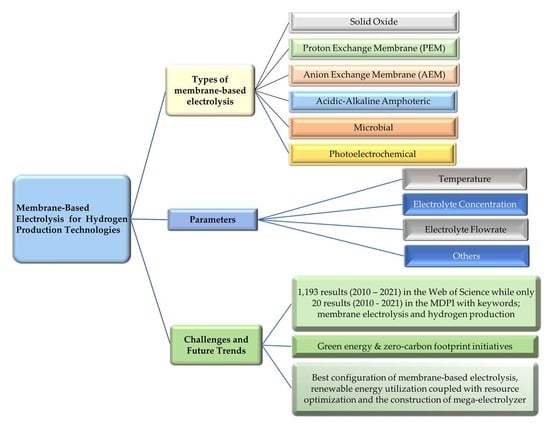
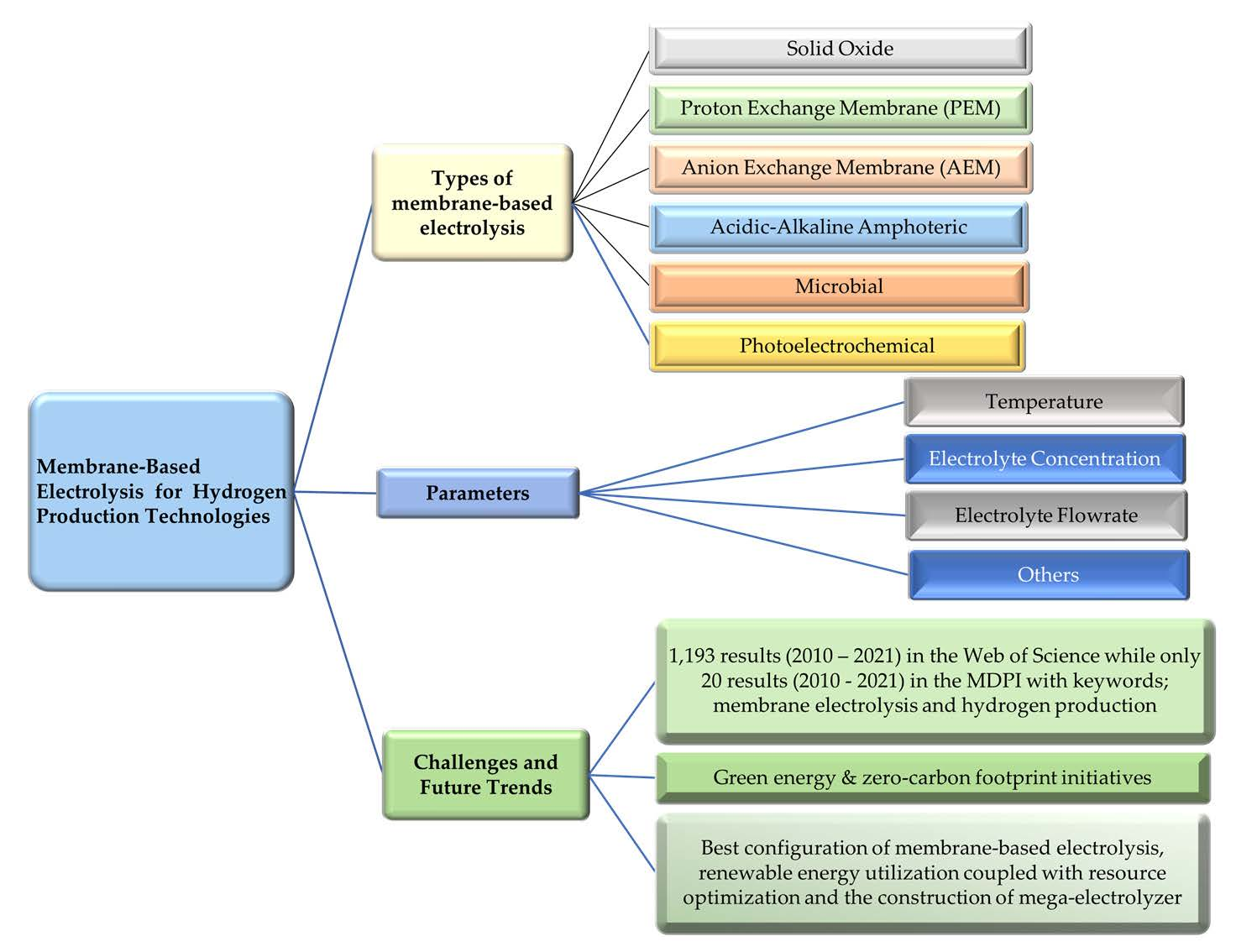
2. Types of Membranes for Hydrogen Production
- High thermal and mechanical stability
- Cost-effective and economic fabrication process
- Excellent ionic conductivity
- Excellent electrical insulation
- High oxidative and hydrolytic stability
- Excellent ability to block ion crossover via membrane/low diffusivity
- Low swelling
- Easy fabrication of the membrane electrode assemblies (MEA)
- High chemical/electrochemical stability
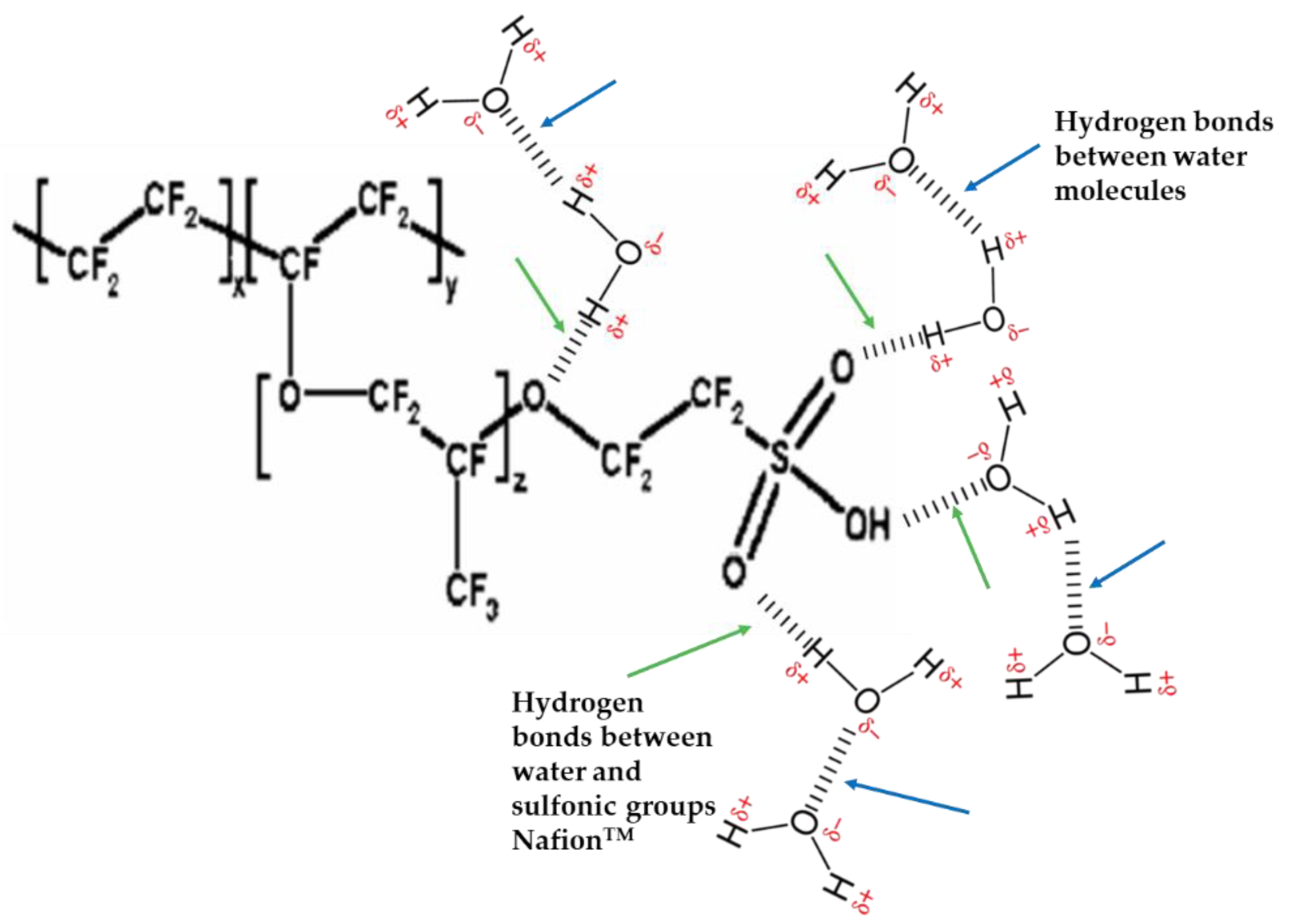
2.1. Nafion™
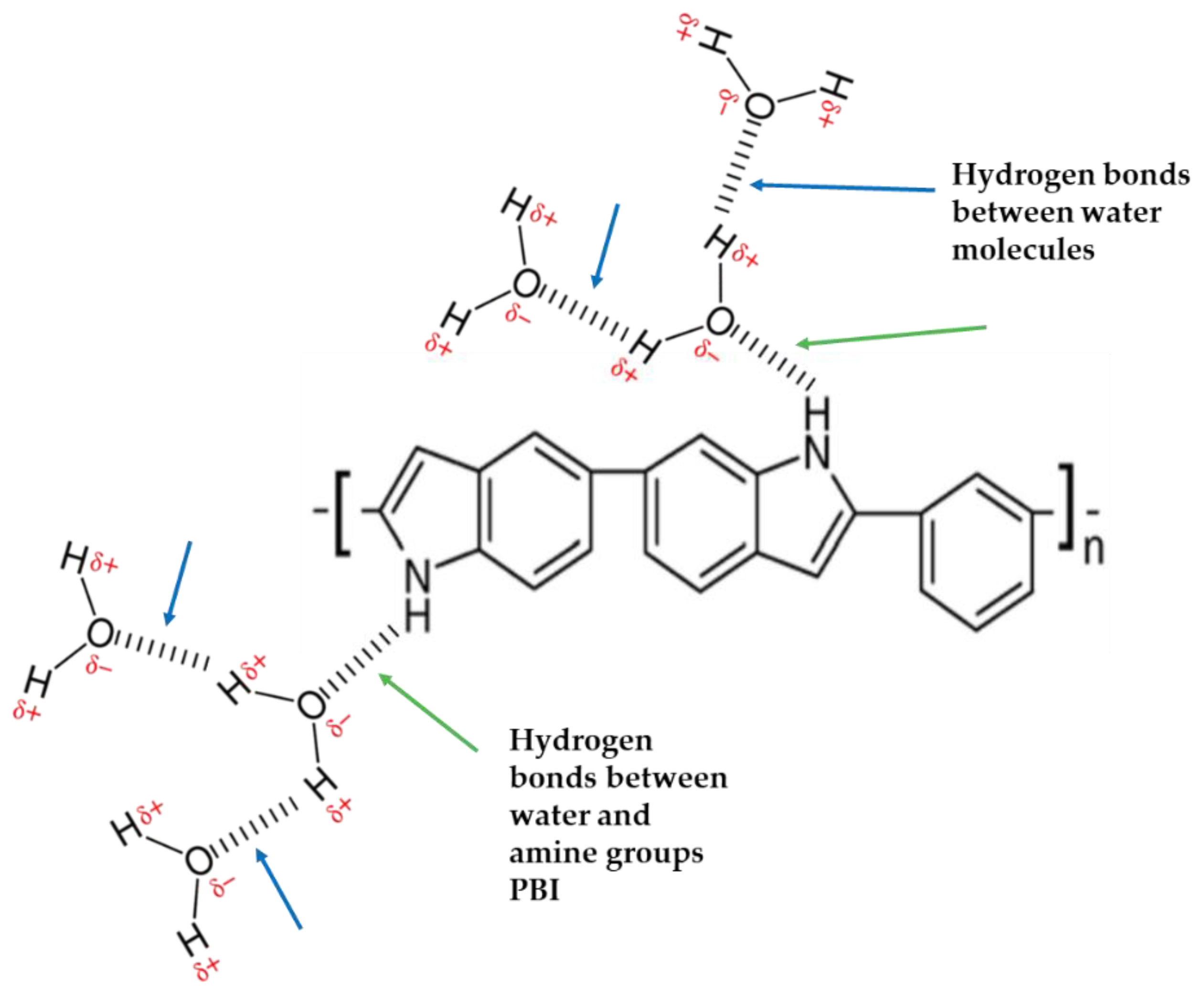
2.2. Polybenzimidazole (PBI)
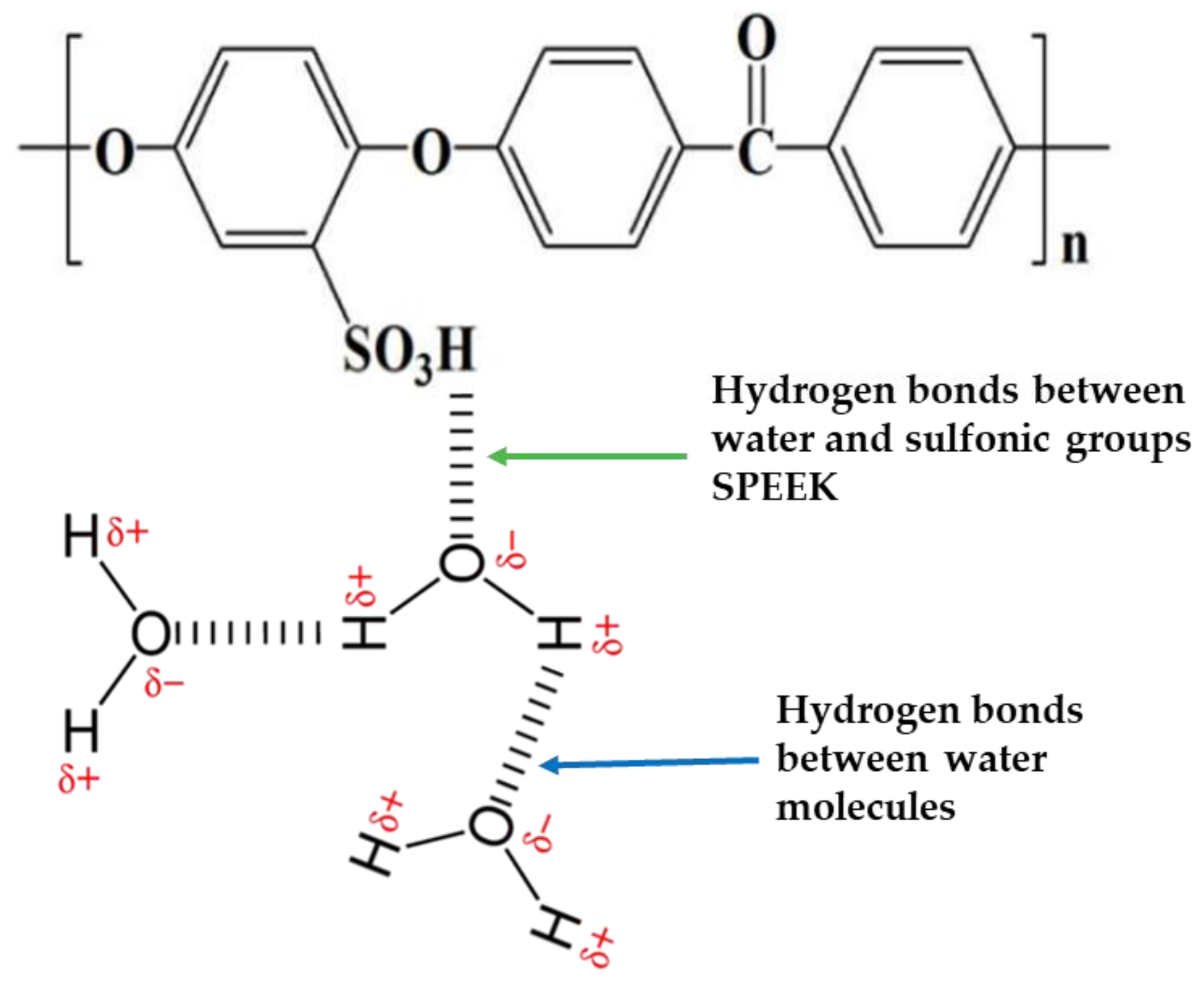
2.3. Sulfonated Polyether Ether Ketone (SPEEK)
2.4. Others
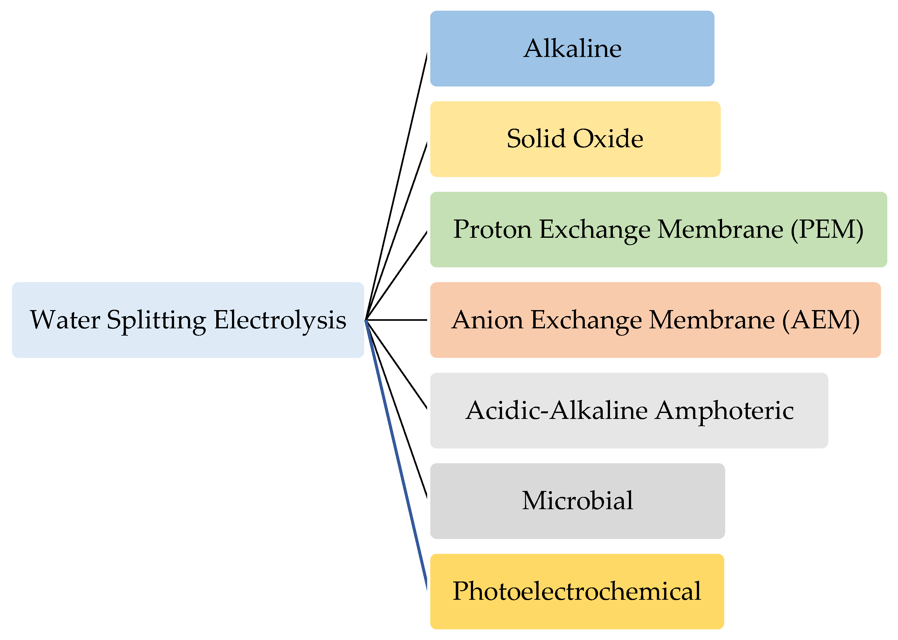
3. Types of Water Electrolysis Technologies
3.1. Nonmembrane-Based Electrolysis
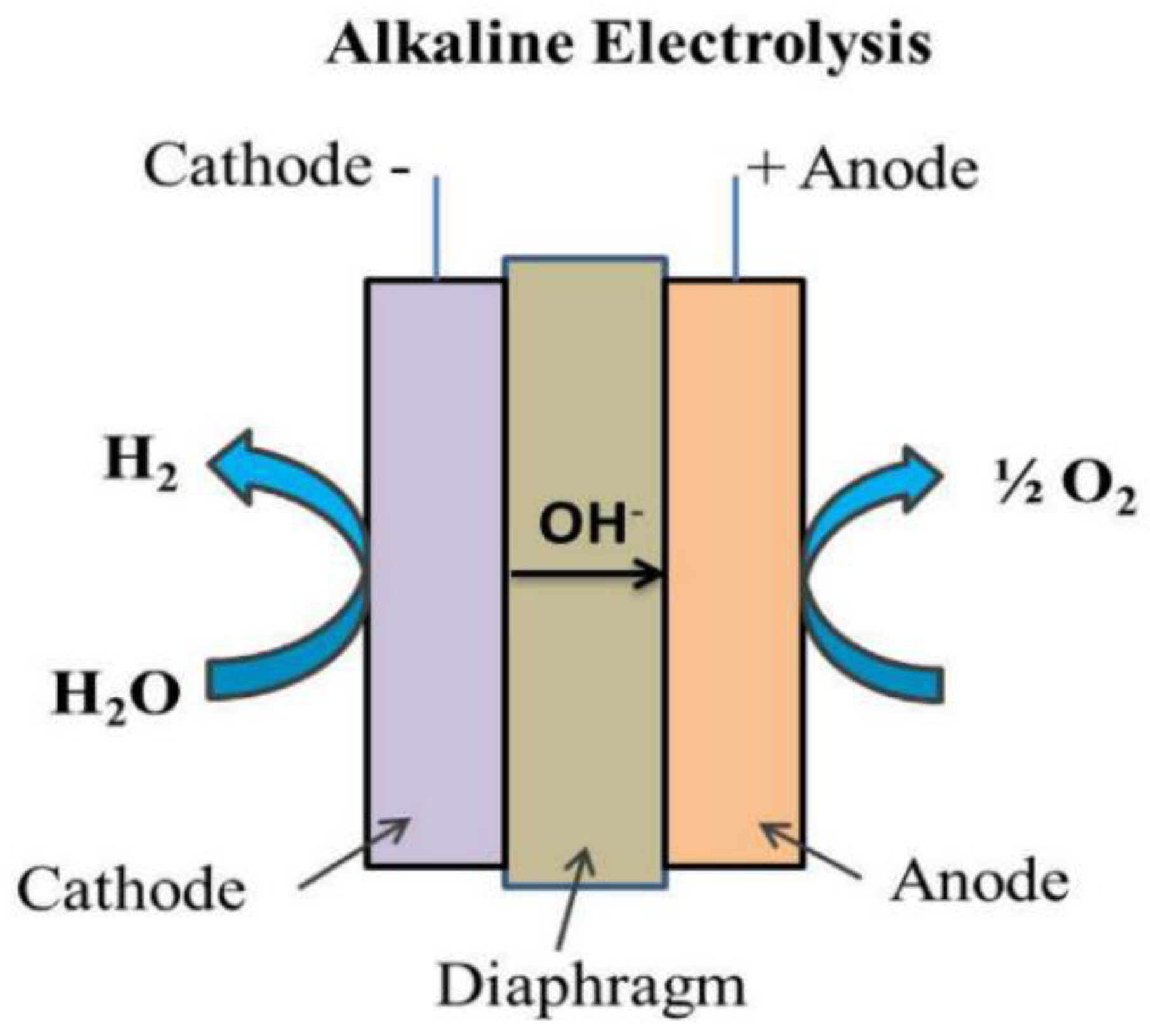
Alkaline Electrolysis
3.2. Membrane-Based Electrolysis
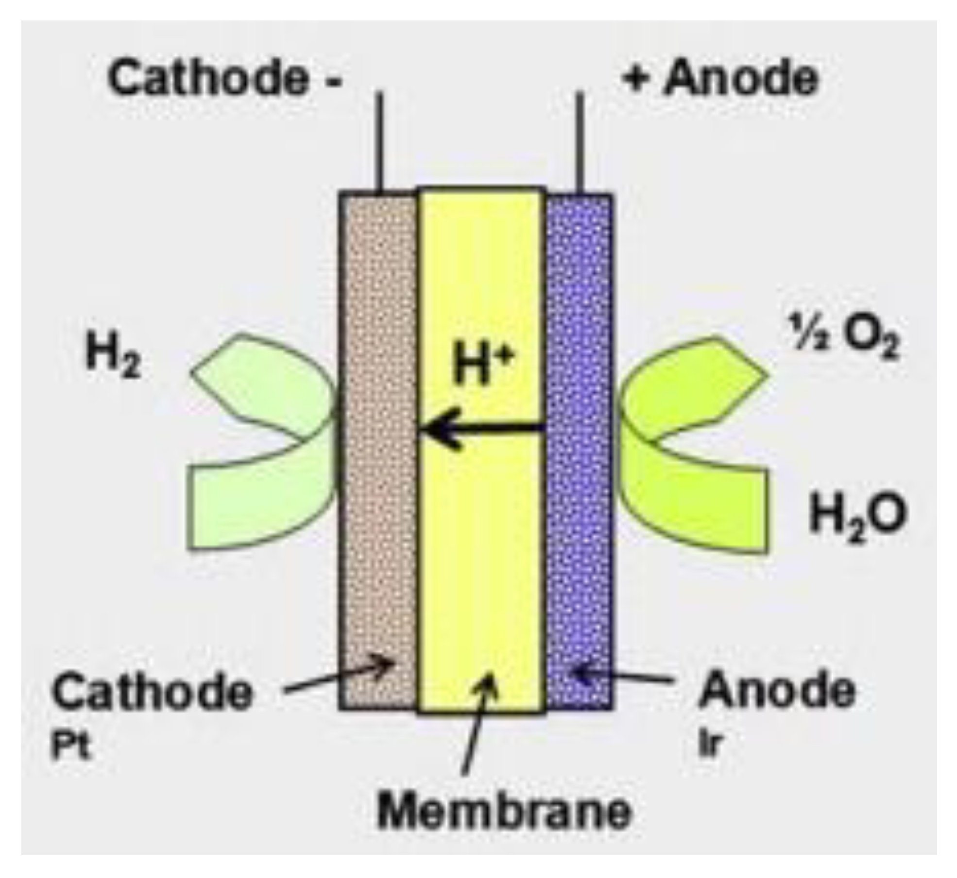
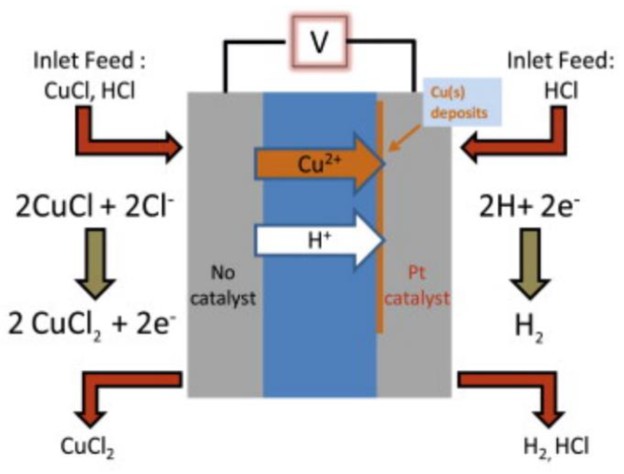
3.2.1. Proton Exchange Membrane Electrolysis
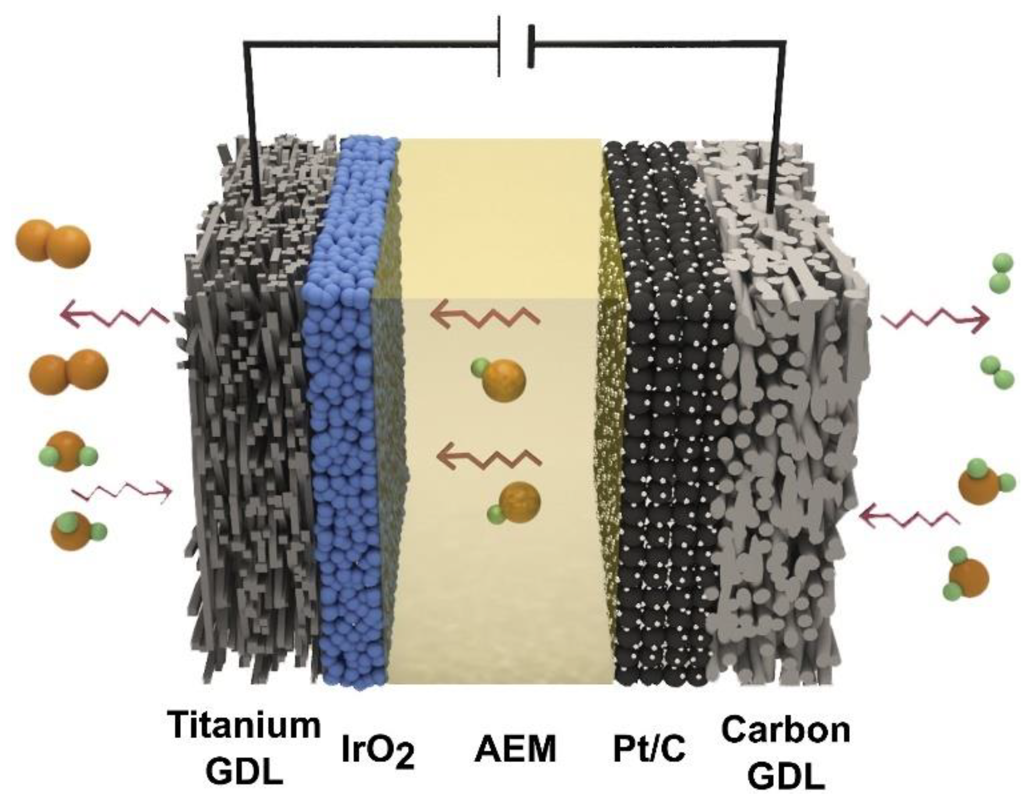
3.2.2. Anion Exchange Membrane (AEM) Electrolysis
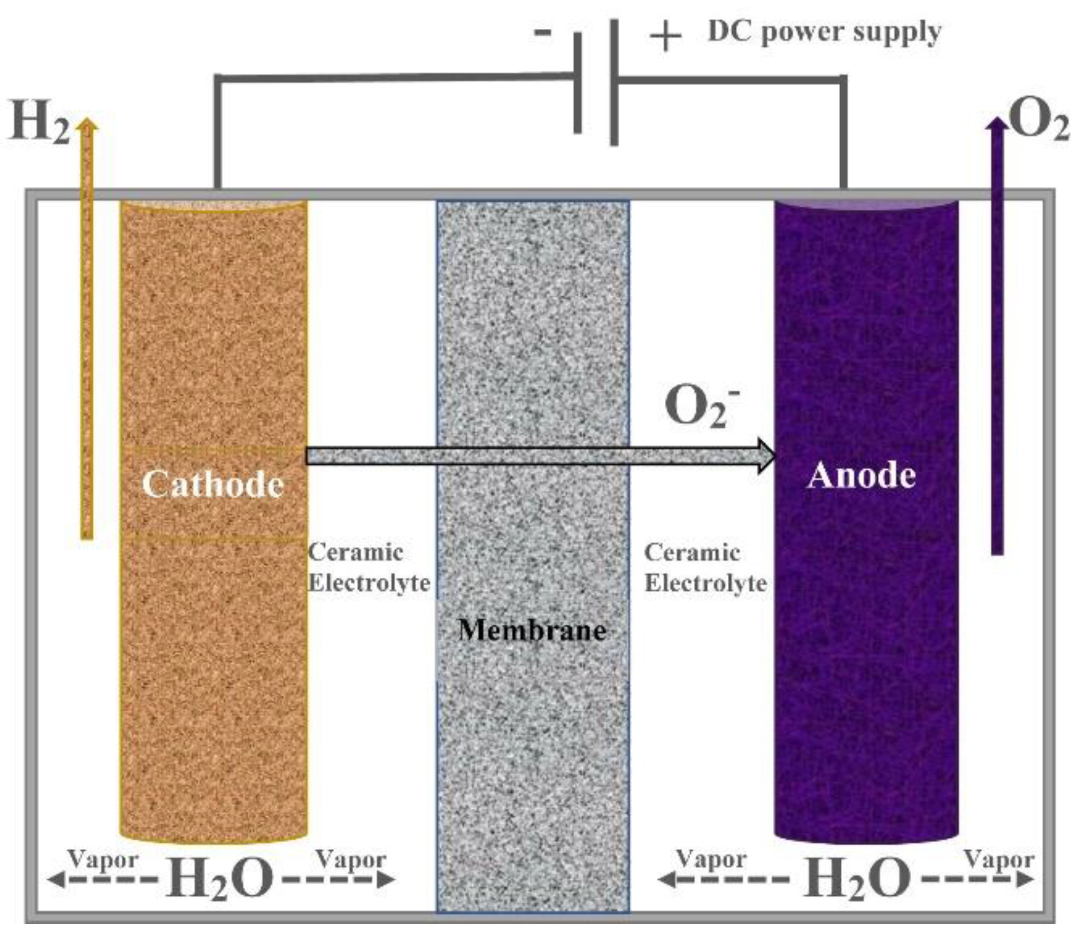
3.2.3. Solid Oxide Electrolysis
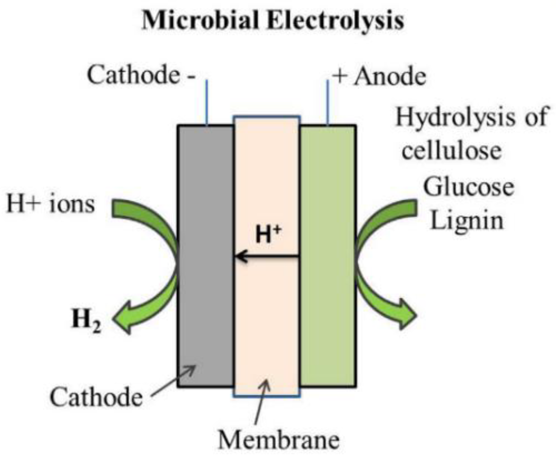
3.2.4. Microbial Electrolysis
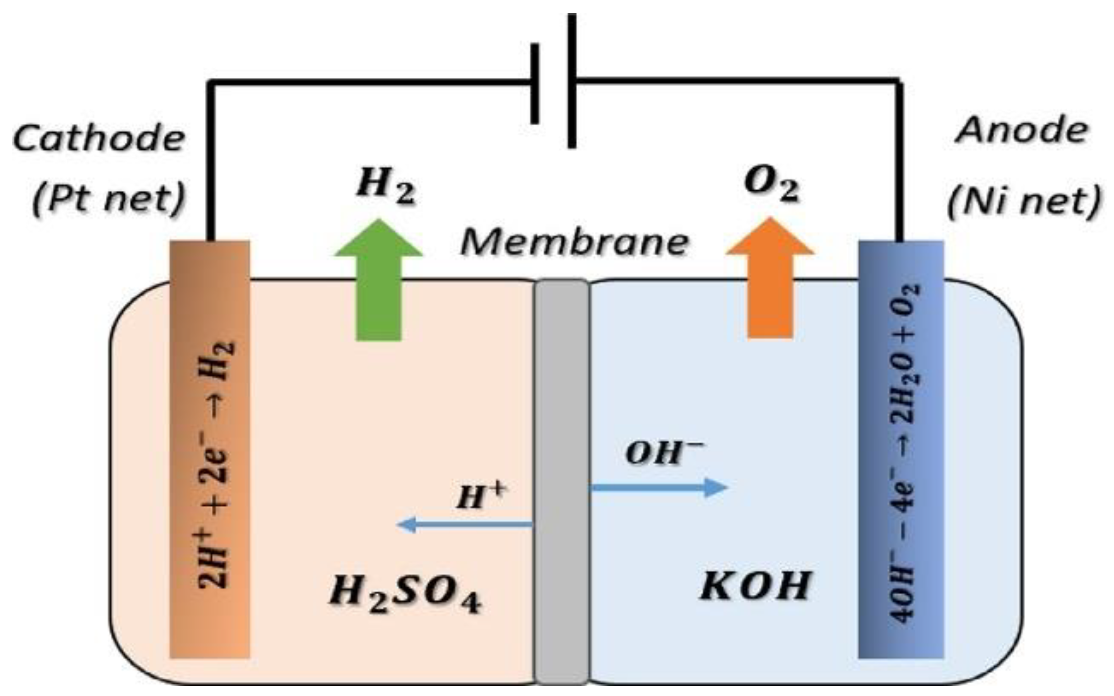
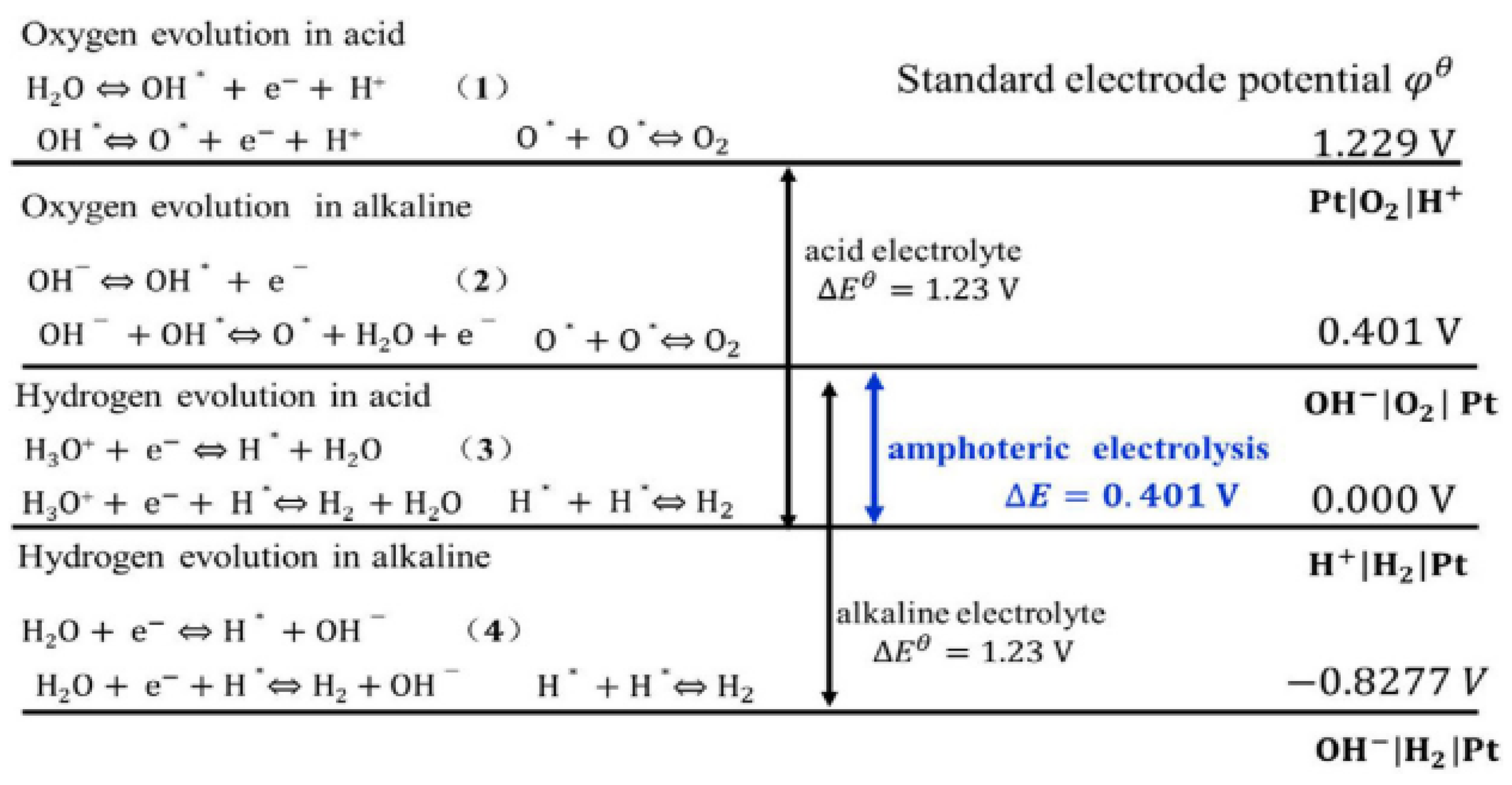
3.2.5. Acid-Alkaline Amphoteric Electrolysis
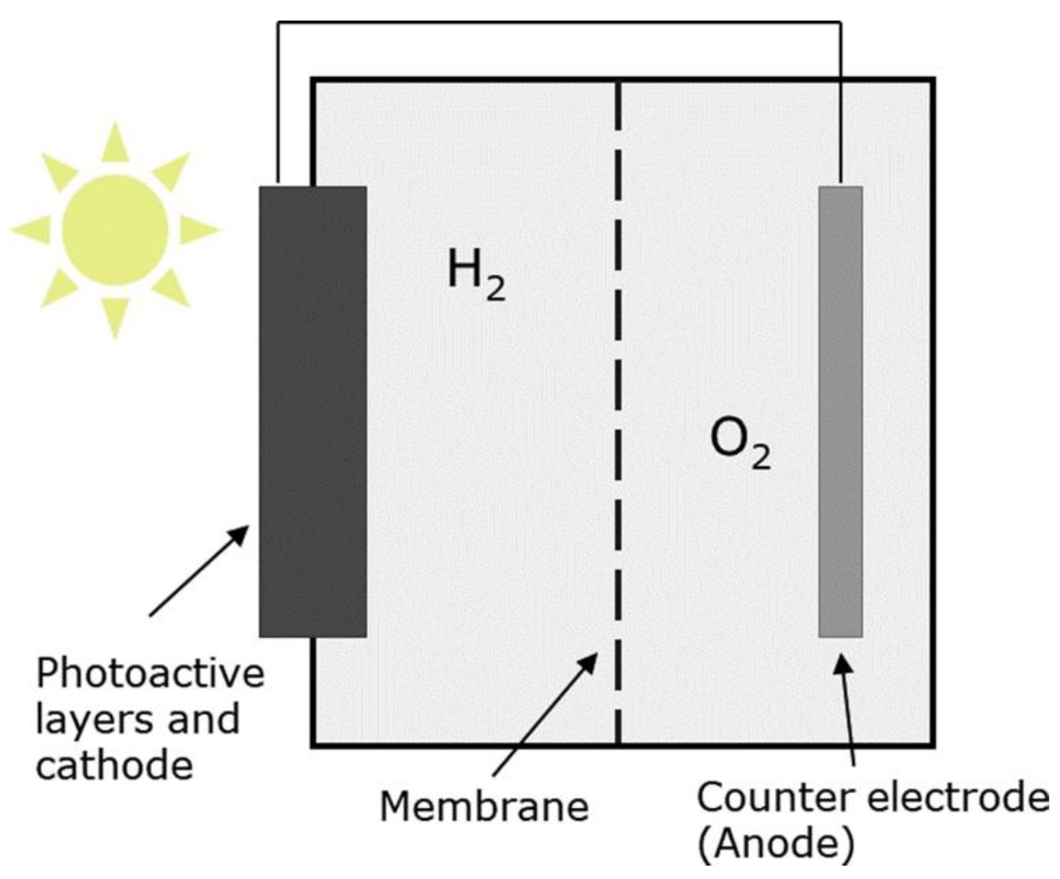
3.2.6. Photoelectrochemical Electrolysis
3.3. Summary
4. Parameters Affecting the Membrane-Based Electrolysis
4.1. Temperature
4.2. Electrolytes Concentration
4.3. Electrolytes Flowrate
4.4. Others
5. Challenges and Future Trends
6. Conclusions
Abbreviation
| AEM | Anion exchange membrane |
| AAA | Acidic-alkaline amphoteric |
| PA | Phosphoric acid |
| PBI | Polybenzimidazole |
| PEEK | Poly ether ether ketone |
| PEM | Proton Exchange Membrane |
| SPEEK | Sulfonated poly ether ether ketone |
| MEC | Microbial electrolysis cell |
| PEC | Photoelectrochemical |
| SOE | Solid oxide electrolysis |
| CuCl-HCl | Copper chloride-hydrochloric acid |
| OER | Oxygen evolution reaction |
| HER | Hydrogen evolution reaction |
| MFC | Microbial fuel cell |
| GHG | Greenhouse gases |
| PBI/ZrP | Polybenzimidazole/Zirconium phosphate |
| PEME | Proton exchange membrane electrolyzer |
| PFSA | Perfluorinated sulfonic acid |
| PEMFC | Proton exchange membrane fuel cell |
| MEA | Membrane electrode assemblies |
| SPES | Sulfonated polyether sulfone |
| YSZ | Yittria stabilized zirconia |
| CGO | Gadolinium doped ceria |
| SSZ | Scadinia stabilized zirconia |
| LDC | Lanthanum doped cerium |
| LSGM | Lanthanum gallate-based electrolyte |
| SPAES | Sulfonated Polyaryl Ether Sulfone |
Author Contributions
Funding
Institutional Review Board Statement
Informed Consent Statement
Data Availability Statement
Acknowledgments
Conflicts of Interest
References
- Da Silva Veras, T.; Mozer, T.S.; da Costa Rubim Messeder dos Santos, D.; da Silva César, A. Hydrogen: Trends, production and characterization of the main process worldwide. Int. J. Hydrogen Energy 2017, 42, 2018–2033. [Google Scholar] [CrossRef]
- Abe, J.O.; Popoola, A.P.I.; Ajenifuja, E.; Popoola, O.M. Hydrogen energy, economy and storage: Review and recommendation. Int. J. Hydrogen Energy 2019, 44, 15072–15086. [Google Scholar] [CrossRef]
- Midilli, A.; Kucuk, H.; Topal, M.E.; Akbulut, U.; Dincer, I. A comprehensive review on hydrogen production from coal gasification: Challenges and Opportunities. Int. J. Hydrogen Energy 2021, 46, 25385–25412. [Google Scholar] [CrossRef]
- Roeb, M.; Monnerie, N.; Houaijia, A.; Thomey, D.; Sattler, C. Solar Thermal Water Splitting. In Renewable Hydrogen Technologies; Elsevier: Amsterdam, The Netherlands, 2013; pp. 63–86. [Google Scholar]
- Hosseini, S.E.; Wahid, M.A. Hydrogen production from renewable and sustainable energy resources: Promising green energy carrier for clean development. Renew. Sustain. Energy Rev. 2016, 57, 850–866. [Google Scholar] [CrossRef]
- Carey, J.; Kennedy, S.; Mastny, L. Global Renewables Outlook: Energy Transformation 2050; IRENA: Abu Dhabi, United Arab Emirates, 2020. [Google Scholar]
- Kumar, R.; Kumar, A.; Pal, A. An overview of conventional and non-conventional hydrogen production methods. Mater. Today Proc. 2020. [Google Scholar] [CrossRef]
- Awadallah, A.E.; Mostafa, M.S.; Aboul-Enein, A.A.; Hanafi, S.A. Hydrogen production via methane decomposition over Al2O3–TiO2 binary oxides supported Ni catalysts: Effect of Ti content on the catalytic efficiency. Fuel 2014, 129, 68–77. [Google Scholar] [CrossRef]
- Ahmad, M.S.; Ali, M.S.; Rahim, N.A. Hydrogen energy vision 2060: Hydrogen as energy Carrier in Malaysian primary energy mix—Developing P2G case. Energy Strateg. Rev. 2021, 35, 100632. [Google Scholar] [CrossRef]
- Owgi, A.H.K.; Jalil, A.A.; Hussain, I.; Hassan, N.S.; Hambali, H.U.; Siang, T.J.; Vo, D.V.N. Catalytic systems for enhanced carbon dioxide reforming of methane: A review. Environ. Chem. Lett. 2021, 19, 2157–2183. [Google Scholar] [CrossRef]
- Oladokun, O.; Ahmad, A.; Abdullah, T.A.T.; Nyakuma, B.B.; Kamaroddin, M.F.A.; Ahmed, M.; Alkali, H. Sensitivity analysis of biohydrogen production from Imperata cylindrica using stoichiometric equilibrium model. J. Teknol. 2016, 78, 137–142. [Google Scholar] [CrossRef] [Green Version]
- Omoniyi, O.; Bacquart, T.; Moore, N.; Bartlett, S.; Williams, K.; Goddard, S.; Lipscombe, B.; Murugan, A.; Jones, D. Hydrogen gas quality for gas network injection: State of the art of three hydrogen production methods. Processes 2021, 9, 1056. [Google Scholar] [CrossRef]
- Abdullah, W.S.W.; Osman, M.; Kadir, M.Z.A.A.; Verayiah, R. The potential and status of renewable energy development in Malaysia. Energies 2019, 12, 2437. [Google Scholar] [CrossRef] [Green Version]
- Stokes, I. Technology Roadmap. Train. Proj. Manag. 2020, 241–246. [Google Scholar] [CrossRef]
- Kimura, S.; Li, Y. Demand and Supply Potential of Hydrogen Energy in East Asia; Economic Research Institute for ASEAN and East Asia: Jakarta, Indonesia, 2019; Volume 01. [Google Scholar]
- Sanguesa, J.A.; Torres-Sanz, V.; Garrido, P.; Martinez, F.J.; Marquez-Barja, J.M. A Review on Electric Vehicles: Technologies and Challenges. Smart Cities 2021, 4, 372–404. [Google Scholar] [CrossRef]
- Gielen, D.; Saygin, D.; Rigter, J. Renewable Energy Prospects: Indonesia; IRENA: Abu Dhabi, United Arab Emirates, 2017; ISBN 1026-1141. [Google Scholar]
- Baykara, S.Z. Hydrogen: A brief overview on its sources, production and environmental impact. Int. J. Hydrogen Energy 2018, 43, 10605–10614. [Google Scholar] [CrossRef]
- Shiva Kumar, S.; Himabindu, V. Hydrogen production by PEM water electrolysis—A review. Mater. Sci. Energy Technol. 2019, 2, 442–454. [Google Scholar] [CrossRef]
- Dawood, F.; Anda, M.; Shafiullah, G.M. Hydrogen production for energy: An overview. Int. J. Hydrogen Energy 2020, 45, 3847–3869. [Google Scholar] [CrossRef]
- Kamaroddin, M.F.A.; Sabli, N.; Nia, P.M.; Abdullah, T.A.T.; Abdullah, L.C.; Izhar, S.; Ripin, A.; Ahmad, A. Phosphoric acid doped composite proton exchange membrane for hydrogen production in medium-temperature copper chloride electrolysis. Int. J. Hydrogen Energy 2020, 45, 22209–22222. [Google Scholar] [CrossRef]
- Nicoletti, G.; Arcuri, N.; Nicoletti, G.; Bruno, R. A technical and environmental comparison between hydrogen and some fossil fuels. Energy Convers. Manag. 2015, 89, 205–213. [Google Scholar] [CrossRef]
- Ren, X.; Dong, L.; Xu, D.; Hu, B. Challenges towards hydrogen economy in China. Int. J. Hydrogen Energy 2020, 45, 34326–34345. [Google Scholar] [CrossRef]
- Nikolaidis, P.; Poullikkas, A. A comparative overview of hydrogen production processes. Renew. Sustain. Energy Rev. 2017, 67, 597–611. [Google Scholar] [CrossRef]
- ESMAP. Green Hydrogen in Amsterdam; ESMAP: Washington DC, USA, 2020. [Google Scholar]
- Soltani, R.; Dincer, I.; Rosen, M.A. Kinetic and electrochemical analyses of a CuCI/HCl electrolyzer. Int. J. Energy Res. 2019, er.4703. [Google Scholar] [CrossRef]
- Bessarabov, D.; Wang, H.; Li, H.; Zhao, N. PEM Electrolysis for Hydrogen Production: Principles and Applications; Bessarabov, D., Wang, H., Li, H., Zhao, N., Eds.; Taylor & Francis: Boca Raton, FL, USA, 2016; ISBN 9781482252323. [Google Scholar]
- Olabi, A.G.; Bahri, A.s.; Abdelghafar, A.A.; Baroutaji, A.; Sayed, E.T.; Alami, A.H.; Rezk, H.; Abdelkareem, M.A. Large-vscale hydrogen production and storage technologies: Current status and future directions. Int. J. Hydrogen Energy 2021, 46, 23498–23528. [Google Scholar] [CrossRef]
- Pinsky, R.; Sabharwall, P.; Hartvigsen, J.; O’Brien, J. Comparative review of hydrogen production technologies for nuclear hybrid energy systems. Prog. Nucl. Energy 2020, 123, 103317. [Google Scholar] [CrossRef]
- Carmo, M.; Fritz, D.L.; Mergel, J.; Stolten, D. A comprehensive review on PEM water electrolysis. Int. J. Hydrogen Energy 2013, 38, 4901–4934. [Google Scholar] [CrossRef]
- Volkov, V.V.; Federation, R.; Deville, S. Encyclopedia of Membranes; Springer: New York, NY, USA, 2016; ISBN 9783662443248. [Google Scholar]
- Hui, T.; Selvaraj, J.; Chein, S.; Chyi, S. Energy policy and alternative energy in Malaysia: Issues and challenges for sustainable growth—An update. Renew. Sustain. Energy Rev. 2018, 81, 3021–3031. [Google Scholar]
- Edwards, R.L.; Font-Palma, C.; Howe, J. The status of hydrogen technologies in the UK: A multi-disciplinary review. Sustain. Energy Technol. Assess. 2021, 43, 100901. [Google Scholar] [CrossRef]
- Lei, Q.; Wang, B.; Wang, P.; Liu, S. Hydrogen generation with acid/alkaline amphoteric water electrolysis. J. Energy Chem. 2019, 38, 162–169. [Google Scholar] [CrossRef] [Green Version]
- Luo, M.; Yi, Y.; Wang, S.; Wang, Z.; Du, M.; Pan, J.; Wang, Q. Review of hydrogen production using chemical-looping technology. Renew. Sustain. Energy Rev. 2018, 81, 3186–3214. [Google Scholar] [CrossRef]
- Natural Resources Canada (NRCan). Seizing the Opportunities for Hydrogen; Natural Resources Canada (NRCan): Hamilton, ON, Canada, 2020; ISBN 9780660367606. [Google Scholar]
- Bockris, J.O.M. The hydrogen economy: Its history. Int. J. Hydrogen Energy 2013, 38, 2579–2588. [Google Scholar] [CrossRef]
- Daud, W.R.W.; Ahmad, A.; Mohamed, A.B.; Kamarudin, S.K.; Koh, J.I.S.; Rasid, N.; Daud, Z.B.; Hasran, U.A.; Samuel, N.; Abdullah, M.I. The Blueprint for Fuel Cell Industries in Malaysia; Academy of Sciences Malaysia: Kuala Lumpur, Malaysia, 2017; ISBN 9789832915300. [Google Scholar]
- Ambrose, A.F.; Al-Amin, A.Q.; Rasiah, R.; Saidur, R.; Amin, N. Prospects for introducing hydrogen fuel cell vehicles in Malaysia. Int. J. Hydrogen Energy 2017, 42, 9125–9134. [Google Scholar] [CrossRef]
- IRENA. Future of Solar Photovoltaic: Deployment, Investment, Technology, Grid Integration and Socio-Economic Aspects (A Global Energy Transformation: Paper); IRENA: Abu Dhabi, United Arab Emirates, 2019; ISBN 9789292601553. [Google Scholar]
- Millet, P.; Grigoriev, S. Water Electrolysis Technologies. In Renewable Hydrogen Technologies: Production, Purification, Storage, Applications and Safety; Elsevier: Amsterdam, The Netherlands, 2013; pp. 19–41. ISBN 9780444563521. [Google Scholar]
- Wu, Q.X.; Pan, Z.F.; An, L. Recent advances in alkali-doped polybenzimidazole membranes for fuel cell applications. Renew. Sustain. Energy Rev. 2018, 89, 168–183. [Google Scholar] [CrossRef]
- Fahid Amin, H.M. Heat Transfer Analysis of PEMFC System Using FEM. Master’s Thesis, Politecnico di Milano, Milan, Italy, 2010. [Google Scholar]
- Kamaroddin, M.F.A.; Sabli, N.; Abdullah, T.A.T. Hydrogen Production by Membrane Water Splitting Technologies. In Advances In Hydrogen Generation Technologies; InTech: London, UK, 2018; pp. 19–37. [Google Scholar]
- María Barragán, V. Short-circuit current in polymeric membrane-based thermocells: An experimental study. Membranes 2021, 11, 480. [Google Scholar] [CrossRef] [PubMed]
- Özdemir, Y.; Özkan, N.; Devrim, Y. Fabrication and Characterization of Cross-linked Polybenzimidazole Based Membranes for High Temperature PEM Fuel Cells. Electrochim. Acta 2017, 245, 1–13. [Google Scholar] [CrossRef]
- Abbasi, R.; Setzler, B.P.; Lin, S.; Wang, J.; Zhao, Y.; Xu, H.; Pivovar, B.; Tian, B.; Chen, X.; Wu, G.; et al. A Roadmap to Low-Cost Hydrogen with Hydroxide Exchange Membrane Electrolyzers. Adv. Mater. 2019, 1805876, 1–14. [Google Scholar] [CrossRef]
- Kamaroddin, M.F.A.; Sabli, N.; Abdullah, T.A.T.; Abdullah, L.C.; Izhar, S.; Ripin, A.; Ahmad, A. Effect of temperature and current density on polybenzimidazole zirconium phosphate hybrid membrane in copper chloride electrolysis for hydrogen production. Int. J. Integr. Eng. 2019, 11, 182–189. [Google Scholar] [CrossRef] [Green Version]
- Escorihuela, J.; Sahuquillo, Ó.; García-Bernabé, A.; Giménez, E.; Compañ, V. Phosphoric acid doped polybenzimidazole (PBI)/Zeolitic imidazolate framework composite membranes with significantly enhanced proton conductivity under low humidity conditions. Nanomaterials 2018, 8, 775. [Google Scholar] [CrossRef] [Green Version]
- Da Burgal, J.P.S. Development of Poly (ether ether ketone) Nanofiltration Membranes for Organic Solvent Nanofiltration in Continuous Flow Systems. Ph.D. Thesis, Imperial College London, London, UK, 2016. [Google Scholar]
- Valtcheva, I. Polybenzimidazole Membranes for Organic Solvent Nanofiltration: Formation Parameters and Applications. Ph.D. Thesis, Imperial College London, London, UK, 2016. [Google Scholar]
- Shaari, N.; Kamarudin, S.K. Recent advances in additive-enhanced polymer electrolyte membrane properties in fuel cell applications: An overview. Int. J. Energy Res. 2019, 43, 2756–2794. [Google Scholar] [CrossRef]
- Di Noto, V.; Zawodzinski, T.A.; Herring, A.M.; Giffin, G.A.; Negro, E.; Lavina, S. Polymer electrolytes for a hydrogen economy. Int. J. Hydrogen Energy 2012, 37, 6120–6131. [Google Scholar] [CrossRef]
- Grigoriev, S.A.; Fateev, V.N. Hydrogen Production by Water Electrolysis, Hydrogen Production Technologies; Scrivener Publishing LLC: Beverly, MA, USA, 2019; pp. 231–276. [Google Scholar]
- Sahu, A.K.; Pitchumani, S.; Sridhar, P.; Shukla, A.K. Nafion and modified-Nafion membranes for polymer electrolyte fuel cells: An overview. Bull. Mater. Sci. 2009, 32, 285–294. [Google Scholar] [CrossRef]
- Rahim, A.H.A.; Salami, A.; Kamarudin, S.K.; Hanapi, S. An overview of polymer electrolyte membrane electrolyzer for hydrogen production: Modeling and mass transport. J. Power Sources 2016, 309, 56–65. [Google Scholar] [CrossRef]
- Lade, H.; Kumar, V.; Arthanareeswaran, G.; Ismail, A.F. Sulfonated poly(arylene ether sulfone) nanocomposite electrolyte membrane for fuel cell applications: A review. Int. J. Hydrogen Energy 2017, 42, 1063–1074. [Google Scholar] [CrossRef]
- Hooshyari, K.; Javanbakht, M.; Shabanikia, A.; Enhessari, M. Fabrication BaZrO3/PBI-based nanocomposite as a new proton conducting membrane for high temperature proton exchange membrane fuel cells. J. Power Sources 2015, 276, 62–72. [Google Scholar] [CrossRef]
- Romano, S.M. Application of Nanofibres in Polymer Composite Membranes for Direct Methanol Fuel Cells. Ph.D. Thesis, Universitat Politècnica de València, Valencia, Spain, 2015. [Google Scholar]
- Mu, D.; Yu, L.; Liu, L.; Xi, J. Rice Paper Reinforced Sulfonated Poly(ether ether ketone) as Low-Cost Membrane for Vanadium Flow Batteries. ACS Sustain. Chem. Eng. 2017, 5, 2437–2444. [Google Scholar] [CrossRef]
- Paidar, M.; Fateev, V.; Bouzek, K. Membrane electrolysis—History, current status and perspective. Electrochim. Acta 2016, 209, 737–756. [Google Scholar] [CrossRef] [Green Version]
- Ying, Y.P.; Kamarudin, S.K.; Masdar, M.S. Silica-related membranes in fuel cell applications: An overview. Int. J. Hydrogen Energy 2018, 1–17. [Google Scholar] [CrossRef]
- Toghyani, S.; Afshari, E.; Baniasadi, E.; Atyabi, S.A.; Naterer, G.F. Thermal and electrochemical performance assessment of a high temperature PEM electrolyzer. Energy 2018, 152, 237–246. [Google Scholar] [CrossRef]
- Araya, S.S.; Zhou, F.; Liso, V.; Sahlin, S.L.; Vang, J.R.; Thomas, S.; Gao, X.; Jeppesen, C.; Kær, S.K. A comprehensive review of PBI-based high temperature PEM fuel cells. Int. J. Hydrogen Energy 2016, 41, 21310–21344. [Google Scholar] [CrossRef]
- Abdol Rahim, A.H.; Tijani, A.S.; Shukri, F.H. Simulation analysis of the effect of temperature on overpotentials in PEM electrolyzer system. J. Mech. Eng. 2015, 12, 47–65. [Google Scholar]
- Ainla, A.; Brandell, D. Nafion®-polybenzimidazole (PBI) composite membranes for DMFC applications. Solid State Ionics 2007, 178, 581–585. [Google Scholar] [CrossRef]
- Wang, Y.; Wang, Q.; Wan, L.Y.; Han, Y.; Hong, Y.; Huang, L.; Yang, X.; Wang, Y.; Zaghib, K.; Zhou, Z. KOH-doped polybenzimidazole membrane for direct hydrazine fuel cell. J. Colloid Interface Sci. 2020, 563, 27–32. [Google Scholar] [CrossRef] [PubMed]
- Sana, B.; Jana, T. Polymer electrolyte membrane from polybenzimidazoles: Influence of tetraamine monomer structure. Polymer (Guildf). 2018, 137, 312–323. [Google Scholar] [CrossRef]
- Yang, J.; Aili, D.; Li, Q.; Xu, Y.; Liu, P.; Che, Q.; Jensen, J.O.; Bjerrum, N.J.; He, R. Benzimidazole grafted polybenzimidazoles for proton exchange membrane fuel cells. Polym. Chem. 2013, 4, 4768–4775. [Google Scholar] [CrossRef] [Green Version]
- Javad, M.; Rowshanzamir, S.; Gashoul, F. Comprehensive investigation of physicochemical and electrochemical properties of sulfonated poly (ether ether ketone) membranes with different degrees of sulfonation for proton exchange membrane fuel cell applications. Energy 2017, 125, 614–628. [Google Scholar] [CrossRef]
- Zhou, Z.; Zholobko, O.; Wu, X.-F.; Aulich, T.; Thakare, J.; Hurley, J. Polybenzimidazole-Based Polymer Electrolyte Membranes for High-Temperature Fuel Cells: Current Status and Prospects. Energies 2021, 14, 135. [Google Scholar] [CrossRef]
- Wan Mohd Noral Azman, W.N.E.; Jaafar, J.; Salleh, W.N.W.; Ismail, A.F.; Othman, M.H.D.; Rahman, M.A.; Rasdi, F.R.M. Highly selective SPEEK/ENR blended polymer electrolyte membranes for direct methanol fuel cell. Mater. Today Energy 2020, 17, 100427. [Google Scholar] [CrossRef]
- Iulianelli, A.; Basile, A. Sulfonated PEEK-based polymers in PEMFC and DMFC applications: A review. Int. J. Hydrogen Energy 2012, 37, 15241–15255. [Google Scholar] [CrossRef]
- Mossayebi, Z.; Saririchi, T.; Rowshanzamir, S.; Parnian, M.J. Investigation and optimization of physicochemical properties of sulfated zirconia/sulfonated poly (ether ether ketone) nanocomposite membranes for medium temperature proton exchange membrane fuel cells. Int. J. Hydrogen Energy 2016, 41, 12293–12306. [Google Scholar] [CrossRef]
- Zhai, S.; Dai, W.; Lin, J.; He, S.; Zhang, B.; Chen, L. Enhanced proton conductivity in sulfonated poly(ether ether ketone) membranes by incorporating sodium dodecyl benzene sulfonate. Polymers 2019, 11. [Google Scholar] [CrossRef] [PubMed] [Green Version]
- Tahrim, A.A.; Amin, I.N.H.M. Advancement in Phosphoric Acid Doped Polybenzimidazole Membrane for High Temperature PEM Fuel Cells: A Review. J. Appl. Membr. Sci. Tech. 2019, 23, 37–62. [Google Scholar] [CrossRef] [Green Version]
- Salarizadeh, P.; Javanbakht, M.; Pourmahdian, S.; Beydaghi, H. Influence of amine-functionalized iron titanate as filler for improving conductivity and electrochemical properties of SPEEK nanocomposite membranes. Chem. Eng. J. 2016, 299, 320–331. [Google Scholar] [CrossRef]
- Ahmad, H.; Kamarudin, S.K.; Hasran, U.A.; Daud, W.R.W. Overview of hybrid membranes for direct-methanol fuel-cell applications. Int. J. Hydrogen Energy 2010, 35, 2160–2175. [Google Scholar] [CrossRef]
- Guo, Y.; Li, G.; Zhou, J.; Liu, Y. Comparison between hydrogen production by alkaline water electrolysis and hydrogen production by PEM electrolysis. IOP Conf. Ser. Earth Environ. Sci. 2019, 371. [Google Scholar] [CrossRef]
- Li, X.; Zhao, L.; Yu, J.; Liu, X.; Zhang, X.; Liu, H.; Zhou, W. Water Splitting: From Electrode to Green Energy System. Nano-Micro Lett. 2020, 12, 1–29. [Google Scholar] [CrossRef]
- Li, C.; Baek, J.B. The promise of hydrogen production from alkaline anion exchange membrane electrolyzers. Nano Energy 2021, 87, 106162. [Google Scholar] [CrossRef]
- Yue, M.; Lambert, H.; Pahon, E.; Roche, R.; Jemei, S.; Hissel, D. Hydrogen energy systems: A critical review of technologies, applications, trends and challenges. Renew. Sustain. Energy Rev. 2021, 146, 111180. [Google Scholar] [CrossRef]
- Wan, L.; Xu, Z.; Wang, P.; Lin, Y.; Wang, B. H2SO4-doped polybenzimidazole membranes for hydrogen production with acid-alkaline amphoteric water electrolysis. J. Memb. Sci. 2021, 618, 118642. [Google Scholar] [CrossRef]
- Escorihuela, J.; García-Bernabé, A.; Compañ, V. A deep insight into different acidic additives as doping agents for enhancing proton conductivity on polybenzimidazole membranes. Polymers 2020, 12, 1374. [Google Scholar] [CrossRef]
- Escorihuela, J.; García-Bernabé, A.; Montero, A.; Andrio, A.; Sahuquillo, Ó.; Gimenez, E.; Compañañ, V. Proton Conductivity through Polybenzimidazole Composite Membranes Containing Silica Nanofiber Mats. Polymers 2019, 11, 1182. [Google Scholar] [CrossRef] [Green Version]
- Sun, X.; Xu, K.; Fleischer, C.; Liu, X.; Grandcolas, M.; Strandbakke, R.; Bjørheim, T.S.; Norby, T.; Chatzitakis, A. Earth-abundant electrocatalysts in proton exchange membrane electrolyzers. Catalysts 2018, 8, 657. [Google Scholar] [CrossRef] [Green Version]
- Kim, D.J.; Choi, D.H.; Park, C.H.; Nam, S.Y. Characterization of the sulfonated PEEK/sulfonated nanoparticles composite membrane for the fuel cell application. Int. J. Hydrogen Energy 2016, 41, 5793–5802. [Google Scholar] [CrossRef]
- Sun, X.; Simonsen, S.C.; Norby, T.; Chatzitakis, A. Composite Membranes for High Temperature PEM Fuel Cells and Electrolysers: A Critical Review. Membranes 2019, 9, 83. [Google Scholar] [CrossRef] [Green Version]
- Dong, Y.; Liu, J.; Sui, M.; Qu, Y.; Ambuchi, J.J.; Wang, H.; Feng, Y. A combined microbial desalination cell and electrodialysis system for copper-containing wastewater treatment and high-salinity-water desalination. J. Hazard. Mater. 2017, 321, 307–315. [Google Scholar] [CrossRef]
- Hitam, C.N.C.; Jalil, A.A. A review on biohydrogen production through photo-fermentation of lignocellulosic biomass. Biomass Convers. Biorefinery 2020. [Google Scholar] [CrossRef]
- Edge, P. The Production and Characterization of Ceramic Carbon Electrode Materials for CuCl—HCl Electrolysis. Master’s Thesis, University of Ontario Institute of Technology, Oshawa, ON, Canada, 2013. [Google Scholar]
- Balashov, V.N.; Schatz, R.S.; Chalkova, E.; Akinfiev, N.N.; Fedkin, M.V.; Lvov, S.N. CuCl Electrolysis for Hydrogen Production in the Cu–Cl Thermochemical Cycle. J. Electrochem. Soc. 2011, 158, B266–B275. [Google Scholar] [CrossRef]
- Aghahosseini, S. System Integration and Optimization of Copper-Chlorine Thermochemical Cycle with Various Options for Hydrogen Production. Ph.D. Thesis, University of Ontario Institute of Technology, Oshawa, ON, Canada, 2013. [Google Scholar]
- Naterer, G.F.; Suppiah, S.; Stolberg, L.; Lewis, M.; Wang, Z.; Rosen, M.A.; Dincer, I.; Gabriel, K.; Odukoya, A.; Secnik, E.; et al. Progress in thermochemical hydrogen production with the copper-chlorine cycle. Int. J. Hydrogen Energy 2015, 40, 6283–6295. [Google Scholar] [CrossRef] [Green Version]
- Abdo, N.; Bradley Easton, E. Nafion/Polyaniline composite membranes for hydrogen production in the Cu-Cl thermochemical cycle. Int. J. Hydrogen Energy 2016, 41, 7892–7903. [Google Scholar] [CrossRef]
- Naterer, G.F.; Suppiah, S.; Stolberg, L.; Lewis, M.; Ferrandon, M.; Wang, Z.; Dincer, I.; Gabriel, K.; Rosen, M.A.; Secnik, E.; et al. Clean hydrogen production with the Cu–Cl cycle—Progress of international consortium, II: Simulations, thermochemical data and materials. Int. J. Hydrogen Energy 2011, 36, 15486–15501. [Google Scholar] [CrossRef]
- Subianto, S. Recent advances in polybenzimidazole/phosphoric acid membranes for high-temperature fuel cells. Polym. Int. 2014, 63, 1134–1144. [Google Scholar] [CrossRef]
- Kamaroddin, M.F.A.; Sabli, N.; Abdullah, T.A.T.; Abdullah, L.C.; Izhar, S.; Ripin, A.; Ahmad, A. Phosphoric Acid Doped Polybenzimidazole and Sulfonated Polyether Ether Ketone Composite Membrane for Hydrogen Production in High-Temperature Copper Chloride Electrolysis. In Proceedings of the IOP Conference Series: Earth and Environmental Science; Institute of Physics Publishing: England, UK, 2019; Volume 268, pp. 1–6. [Google Scholar]
- Aghahosseini, S.; Dincer, I.; Naterer, G.F. Linear sweep voltammetry measurements and factorial design model of hydrogen production by HCl/CuCl electrolysis. Int. J. Hydrogen Energy 2013, 38, 12704–12717. [Google Scholar] [CrossRef]
- Schatz, R.; Kim, S.; Khurana, S.; Fedkin, M.; Lvov, S.N. High Efficiency CuCl Electrolyzer for Cu-Cl Thermochemical Cycle. ECS Trans. 2013, 50, 153–164. [Google Scholar] [CrossRef]
- Marin, G.D.; Wang, Z.; Naterer, G.F.; Gabriel, K. Byproducts and reaction pathways for integration of the Cu–Cl cycle of hydrogen production. Int. J. Hydrogen Energy 2011, 36, 13414–13424. [Google Scholar] [CrossRef]
- Krüger, A.J.; Kerres, J.; Kerres, J.; Krieg, H.M.; Bessarabov, D. Electrochemical Hydrogen Production from SO2 and Water in a SDE Electrolyzer. Hydrog. Prod. Technol. 2017, 277–303. [Google Scholar] [CrossRef]
- Giddey, S.; Badwal, S.P.S.; Ju, H. Polymer electrolyte membrane technologies integrated with renewable energy for hydrogen production. In Current Trends and Future Developments on (Bio-); Membranes; Elsevier Inc.: Amsterdam, The Netherlands, 2019; pp. 235–259. ISBN 9780128135457. [Google Scholar]
- Chi, J.; Yu, H. Water electrolysis based on renewable energy for hydrogen production. Cuihua Xuebao/Chin. J. Catal. 2018, 39, 390–394. [Google Scholar] [CrossRef]
- Escorihuela, J.; García-Bernabé, A.; Montero, Á.; Sahuquillo, Ó.; Giménez, E.; Compañ, V. Ionic liquid composite polybenzimidazol membranes for high temperature PEMFC applications. Polymers 2019, 11, 732. [Google Scholar] [CrossRef] [Green Version]
- Babic, U.; Suermann, M.; Büchi, F.N.; Gubler, L.; Schmidt, T.J. Critical Review—Identifying Critical Gaps for Polymer Electrolyte Water Electrolysis Development. J. Electrochem. Soc. 2017, 164, F387–F399. [Google Scholar] [CrossRef] [Green Version]
- Park, J.E.; Kang, S.Y.; Oh, S.H.; Kim, J.K.; Lim, M.S.; Ahn, C.Y.; Cho, Y.H.; Sung, Y.E. High-performance anion-exchange membrane water electrolysis. Electrochim. Acta 2019, 295, 99–106. [Google Scholar] [CrossRef]
- Leng, Y.; Chen, G.; Mendoza, A.J.; Tighe, T.B.; Hickner, M.A. Solid-State Water Electrolysis with an Alkaline Membrane. J. Am. Chem. Soc. 2012, 134, 9054–9057. [Google Scholar] [CrossRef]
- Pavel, C.C.; Cecconi, F.; Emiliani, C.; Santiccioli, S.; Scaffidi, A.; Catanorchi, S.; Comotti, M. Highly efficient platinum group metal free based membrane-electrode assembly for anion exchange membrane water electrolysis. Angew. Chemie—Int. Ed. 2014, 53, 1378–1381. [Google Scholar] [CrossRef]
- Qian, W.; Shang, Y.; Fang, M.; Wang, S.; Xie, X. Sulfonated polybenzimidazole/zirconium phosphate composite membranes for high temperature applications. Int. J. Hydrogen Energ. 2012, 7, 5–10. [Google Scholar] [CrossRef]
- Wu, X.; Scott, K. CuxCo3-xO4 (0 ≤ x <1) nanoparticles for oxygen evolution in high performance alkaline exchange membrane water electrolysers. J. Mater. Chem. 2011, 21, 12344–12351. [Google Scholar] [CrossRef]
- Seetharaman, S.; Balaji, R.; Ramya, K.; Dhathathreyan, K.S.; Velan, M. Graphene oxide modified non-noble metal electrode for alkaline anion exchange membrane water electrolyzers. Int. J. Hydrogen Energy 2013, 38, 14934–14942. [Google Scholar] [CrossRef]
- Joe, J.D.; Kumar, D.B.S.; Sivakumar, P. Production of Hydrogen By Anion Exchange Membrane Using AWE. Int. J. Sci. Technol. Res. 2014, 3, 38–42. [Google Scholar]
- Anwar, S.; Khan, F.; Zhang, Y.; Djire, A. Recent development in electrocatalysts for hydrogen production through water electrolysis. Int. J. Hydrogen Energy 2021, 46, 32284–32317. [Google Scholar] [CrossRef]
- Dingenen, F.; Verbruggen, S.W. Tapping hydrogen fuel from the ocean: A review on photocatalytic, photoelectrochemical and electrolytic splitting of seawater. Renew. Sustain. Energy Rev. 2021, 142, 110866. [Google Scholar] [CrossRef]
- Nechache, A.; Han, F.; Semerad, R.; Schiller, G.; Costa, R. Evaluation of Performance and Degradation Profiles of a Metal Supported Solid Oxide Fuel Cell under Electrolysis Operation. ECS Trans. 2017, 78, 3039–3047. [Google Scholar] [CrossRef]
- Chen, T.; Zhou, Y.; Liu, M.; Yuan, C.; Ye, X.; Zhan, Z.; Wang, S. High performance solid oxide electrolysis cell with impregnated electrodes. Electrochem. Commun. 2015, 54, 23–27. [Google Scholar] [CrossRef]
- Shen, F.; Wang, R.; Tucker, M.C. Long term durability test and post mortem for metal-supported solid oxide electrolysis cells. J. Power Sources 2020, 474, 228618. [Google Scholar] [CrossRef]
- Wu, S.-H.; Lin, J.-K.; Shiu, W.-H.; Liu, C.-K.; Lin, T.-N.; Lee, R.-Y.; Ting, H.-C.; Lin, H.-H.; Cheng, Y.-N. Performance Test for Anode-Supported And Metal-Supported Solid Oxide Electrolysis Cell Under Different Current Densities. In Proceedings of the 42nd International Conference on Advanced Ceramics and Composites, Ceramic Engineering and Science; John Wiley & Sons: Hoboken, NJ, USA, 2019; Volume 39, pp. 139–148. [Google Scholar] [CrossRef]
- Hwang, C.S.; Tsai, C.H.; Hwang, T.J.; Chang, C.L.; Yang, S.F.; Lin, J.K. Novel Metal Substrates for High Power Metal-supported Solid Oxide Fuel Cells. Fuel Cells 2016, 16, 244–251. [Google Scholar] [CrossRef]
- Kumar, G.; Sivagurunathan, P.; Pugazhendhi, A.; Thi, N.B.D.; Zhen, G.; Chandrasekhar, K.; Kadier, A. A comprehensive overview on light independent fermentative hydrogen production from wastewater feedstock and possible integrative options. Energy Convers. Manag. 2017, 141, 390–402. [Google Scholar] [CrossRef]
- Haron, R.; Mat, R.; Tuan Abdullah, T.A.; Rahman, R.A. Overview on utilization of biodiesel by-product for biohydrogen production. J. Clean. Prod. 2018, 172, 314–324. [Google Scholar] [CrossRef]
- Park, S.G.; Chae, K.J.; Lee, M. A sulfonated poly(arylene ether sulfone)/polyimide nanofiber composite proton exchange membrane for microbial electrolysis cell application under the coexistence of diverse competitive cations and protons. J. Memb. Sci. 2017, 540, 165–173. [Google Scholar] [CrossRef]
- Chae, K.J.; Kim, K.Y.; Choi, M.J.; Yang, E.; Kim, I.S.; Ren, X.; Lee, M. Sulfonated polyether ether ketone (SPEEK)-based composite proton exchange membrane reinforced with nanofibers for microbial electrolysis cells. Chem. Eng. J. 2014, 254, 393–398. [Google Scholar] [CrossRef]
- Lim, S.S.; Daud, W.R.W.; Md Jahim, J.; Ghasemi, M.; Chong, P.S.; Ismail, M. Sulfonated poly(ether ether ketone)/poly(ether sulfone) composite membranes as an alternative proton exchange membrane in microbial fuel cells. Int. J. Hydrogen Energy 2012, 37, 11409–11424. [Google Scholar] [CrossRef]
- Kadier, A.; Simayi, Y.; Abdeshahian, P.; Azman, N.F.; Chandrasekhar, K.; Kalil, M.S. A comprehensive review of microbial electrolysis cells (MEC) reactor designs and configurations for sustainable hydrogen gas production. Alexandria Eng. J. 2016, 55, 427–443. [Google Scholar] [CrossRef] [Green Version]
- Martínez-Merino, V.; Gil, M.J.; Cornejo, A. Biological Hydrogen Production. Renew. Hydrog. Technol. Prod. Purif. Storage Appl. Saf. 2013, 171–199. [Google Scholar] [CrossRef]
- Islam, A.K.M.K.; Dunlop, P.S.M.; Hewitt, N.J.; Lenihan, R.; Brandoni, C. Bio-Hydrogen Production from Wastewater: A Comparative Study of Low Energy Intensive Production Processes. Clean Technol. 2021, 3, 156–182. [Google Scholar] [CrossRef]
- Liu, H.; Grot, S.; Logan, B.E. Electrochemically assisted microbial production of hydrogen from acetate. Environ. Sci. Technol. 2005, 39, 4317–4320. [Google Scholar] [CrossRef]
- Rozendal, R.A.; Jeremiasse, A.W.; Hamelers, H.V.M.; Buisman, C.J.N. Hydrogen production with a microbial biocathode. Environ. Sci. Technol. 2008, 42, 629–634. [Google Scholar] [CrossRef] [PubMed]
- Selembo, P.A.; Merrill, M.D.; Logan, B.E. The use of stainless steel and nickel alloys as low-cost cathodes in microbial electrolysis cells. J. Power Sources 2009, 190, 271–278. [Google Scholar] [CrossRef]
- Foley, J.M.; Rozendal, R.A.; Hertle, C.K.; Lant, P.A.; Rabaey, K. Life cycle assessment of high-rate anaerobic treatment, microbial fuel cells, and microbial electrolysis cells. Environ. Sci. Technol. 2010, 44, 3629–3637. [Google Scholar] [CrossRef] [PubMed]
- Van Eerten-Jansen, M.C.A.; Eerten-Jansen, V.; Ter Heijne, A.; Buisman, C.J.N.; Hamelers, H.V.M. Microbial electrolysis cells for production of methane from CO2: Long-term performance and perspectives. Int. J. Energy Res. 2012, 36, 809–819. [Google Scholar] [CrossRef] [Green Version]
- Dhar, B.R.; Elbeshbishy, E.; Hafez, H.; Lee, H.S. Hydrogen production from sugar beet juice using an integrated biohydrogen process of dark fermentation and microbial electrolysis cell. Bioresour. Technol. 2015, 198, 223–230. [Google Scholar] [CrossRef]
- Colantonio, N.; Kim, Y. Cadmium (II) removal mechanisms in microbial electrolysis cells. J. Hazard. Mater. 2016, 311, 134–141. [Google Scholar] [CrossRef]
- Liu, Z.; Zhou, A.; Zhang, J.; Wang, S.; Luan, Y.; Liu, W.; Wang, A.; Yue, X. Hydrogen Recovery from Waste Activated Sludge: Role of Free Nitrous Acid in a Prefermentation-Microbial Electrolysis Cells System. ACS Sustain. Chem. Eng. 2018, 6, 3870–3878. [Google Scholar] [CrossRef]
- Miller, A.; Singh, L.; Wang, L.; Liu, H. Linking internal resistance with design and operation decisions in microbial electrolysis cells. Environ. Int. 2019, 126, 611–618. [Google Scholar] [CrossRef]
- Wang, L.; Chen, Y.; Long, F.; Singh, L.; Trujillo, S.; Xiao, X.; Liu, H. Breaking the loop: Tackling homoacetogenesis by chloroform to halt hydrogen production-consumption loop in single chamber microbial electrolysis cells. Chem. Eng. J. 2020, 389, 124436. [Google Scholar] [CrossRef]
- Xu, J.; Amorim, I.; Li, Y.; Li, J.; Yu, Z.; Zhang, B.; Araujo, A.; Zhang, N.; Liu, L. Stable overall water splitting in an asymmetric acid/alkaline electrolyzer comprising a bipolar membrane sandwiched by bifunctional cobalt-nickel phosphide nanowire electrodes. Carbon Energy 2020, 2, 646–655. [Google Scholar] [CrossRef]
- Alfaifi, B.Y.; Ullah, H.; Alfaifi, S.; Tahir, A.A.; Mallick, T.K. Photoelectrochemical solar water splitting: From basic principles to advanced devices. Veruscript Funct. Nanomater. 2018, 2, BDJOC3. [Google Scholar] [CrossRef]
- Hashimoto, K.; Irie, H.; Fujishima, A. Invited Review Paper TiO 2 Photocatalysis: A Historical Overview and Future Prospects. Jpn. J. Appl. Phys. 2005, 44, 8269–8285. [Google Scholar] [CrossRef]
- Grimm, A.; de Jong, W.A.; Kramer, G.J. Renewable hydrogen production: A techno-economic comparison of photoelectrochemical cells and photovoltaic-electrolysis. Int. J. Hydrogen Energy 2020, 45, 22545–22555. [Google Scholar] [CrossRef]
- Joy, J.; Mathew, J.; George, S.C. Nanomaterials for photoelectrochemical water splitting—Review. Int. J. Hydrogen Energy 2018, 43, 4804–4817. [Google Scholar] [CrossRef]
- Zhang, B.; Zhang, S.-X.; Yao, R.; Wu, Y.-H.; Qiu, J.-S. Progress and prospects of hydrogen production: Opportunities and challenges. J. Electron. Sci. Technol. 2021, 100080. [Google Scholar] [CrossRef]
- Seger, B.; Pedersen, T.; Laursen, A.B.; Vesborg, P.C.K.; Hansen, O.; Chorkendorff, I. Using TiO2 as a conductive protective layer for photocathodic H2 evolution. J. Am. Chem. Soc. 2013, 135, 1057–1064. [Google Scholar] [CrossRef]
- Lo, C.C.; Huang, C.W.; Liao, C.H.; Wu, J.C.S. Novel twin reactor for separate evolution of hydrogen and oxygen in photocatalytic water splitting. Int. J. Hydrogen Energy 2010, 35, 1523–1529. [Google Scholar] [CrossRef]
- Yu, S.C.; Huang, C.W.; Liao, C.H.; Wu, J.C.S.; Chang, S.T.; Chen, K.H. A novel membrane reactor for separating hydrogen and oxygen in photocatalytic water splitting. J. Memb. Sci. 2011, 382, 291–299. [Google Scholar] [CrossRef]
- Tsydenov, D.E.; Parmon, V.N.; Vorontsov, A.V. Toward the design of asymmetric photocatalytic membranes for hydrogen production: Preparation of TiO2-based membranes and their properties. Int. J. Hydrogen Energy 2012, 37, 11046–11060. [Google Scholar] [CrossRef]
- Liao, C.H.; Huang, C.W.; Wu, J.C.S. Novel dual-layer photoelectrode prepared by RF magnetron sputtering for photocatalytic water splitting. Int. J. Hydrogen Energy 2012, 37, 11632–11639. [Google Scholar] [CrossRef]
- Marschall, R.; Klaysom, C.; Mukherji, A.; Wark, M.; Lu, G.Q.; Wang, L. Composite proton-conducting polymer membranes for clean hydrogen production with solar light in a simple photoelectrochemical compartment cell. Int. J. Hydrogen Energy 2012, 37, 4012–4017. [Google Scholar] [CrossRef]
- Klaysom, C.; Marschall, R.; Wang, L.; Ladewig, B.P.; Lu, G.Q.M. Synthesis of composite ion-exchange membranes and their electrochemical properties for desalination applications. J. Mater. Chem. 2010, 20, 4669–4674. [Google Scholar] [CrossRef]
- Saba, S.M.; Müller, M.; Robinius, M.; Stolten, D. The investment costs of electrolysis – A comparison of cost studies from the past 30 years. Int. J. Hydrogen Energy 2018, 43, 1209–1223. [Google Scholar] [CrossRef]
- Toghyani, S.; Fakhradini, S.; Afshari, E.; Baniasadi, E.; Abdollahzadeh Jamalabadi, M.Y.; Safdari Shadloo, M. Optimization of operating parameters of a polymer exchange membrane electrolyzer. Int. J. Hydrogen Energy 2019, 44, 6403–6414. [Google Scholar] [CrossRef]
- Colli, A.N.; Girault, H.H.; Battistel, A. Non-precious electrodes for practical alkaline water electrolysis. Materials 2019, 12, 1336. [Google Scholar] [CrossRef] [PubMed] [Green Version]
- Naterer, G.F.; Suppiah, S.; Rosen, M.A.; Gabriel, K.; Dincer, I.; Jianu, O.A.; Wang, Z.; Easton, E.B.; Ikeda, B.M.; Rizvi, G.; et al. Advances in unit operations and materials for the Cu-Cl cycle of hydrogen production. Int. J. Hydrogen Energy 2017, 42, 15708–15723. [Google Scholar] [CrossRef]
- Sapountzi, F.M.; Gracia, J.M.; Weststrate, C.J.; Fredriksson, H.O.A.; Niemantsverdriet, F.J.W. Electrocatalysts for the generation of hydrogen, oxygen and synthesis gas. Prog. Energy Combust. Sci. 2017, 58, 1–35. [Google Scholar] [CrossRef] [Green Version]
- Mališ, J.; Mazúr, P.; Paidar, M.; Bystron, T.; Bouzek, K. Nafion 117 stability under conditions of PEM water electrolysis at elevated temperature and pressure. Int. J. Hydrogen Energy 2016, 41, 2177–2188. [Google Scholar] [CrossRef]
- Avramov, S.G.; Lefterova, E.; Penchev, H.; Sinigersky, V.; Slavcheva, E. Comparative study on the proton conductivity of perfluorosulfonic and polybenzimidazole based polymer electrolyte membranes. Bulg. Chem. Commun. 2016, 48, 43–50. [Google Scholar]
- Nguyen, T.; Abdin, Z.; Holm, T.; Mérida, W. Grid-connected hydrogen production via large-scale water electrolysis. Energy Convers. Manag. 2019, 200, 112108. [Google Scholar] [CrossRef]
- Dincer, I.; Acar, C. Innovation in hydrogen production. Int. J. Hydrogen Energy 2017, 42, 14843–14864. [Google Scholar] [CrossRef]
- Chakik, F.E.; Kaddami, M.; Mikou, M. Effect of operating parameters on hydrogen production by electrolysis of water. Int. J. Hydrogen Energy 2017, 42, 25550–25557. [Google Scholar] [CrossRef]
- Haque, M.A.; Sulong, A.B.; Loh, K.S.; Majlan, E.H.; Husaini, T.; Rosli, R.E. Acid doped polybenzimidazoles based membrane electrode assembly for high temperature proton exchange membrane fuel cell: A review. Int. J. Hydrogen Energy 2017, 42, 9156–9179. [Google Scholar] [CrossRef]
- Rashid, M.; Al Mesfer, M.K.; Naseem, H.; Danish, M. Hydrogen Production by Water Electrolysis: A Review of Alkaline Water Electrolysis, PEM Water Electrolysis and High Temperature Water Electrolysis. Int. J. of Eng. Adv. Technol. (IJEAT) 2015, 4, 80–93. [Google Scholar]
- Ursua, A.; Sanchis, P.; Gandia, L.M. Hydrogen Production from Water Electrolysis: Current Status and Future Trends. Proc. IEEE 2012, 100, 410–426. [Google Scholar] [CrossRef]
- Hall, D.M.; Lvov, S.N. Modeling a CuCl(aq)/HCl(aq) Electrolyzer using Thermodynamics and Electrochemical Kinetics. Electrochim. Acta 2016, 190, 1167–1174. [Google Scholar] [CrossRef] [Green Version]
- Han, B.; Mo, J.; Kang, Z.; Yang, G.; Barnhill, W. Modeling of two-phase transport in proton exchange membrane electrolyzer cells for hydrogen energy. Int. J. Hydrogen Energy 2017, 42, 4478–4489. [Google Scholar] [CrossRef] [Green Version]
- Koponen, J.; Kosonen, A.; Ahola, J. Review of Water Electrolysis Technologies and Design of Renewable Hydrogen Production Systems; Lappeenranta University of Technology: Lappeenranta, Finland, 2015. [Google Scholar]
- Godula-Jopek, A. (Ed.) Hydrogen Production by Electrolysis; Wiley-VCH: Hoboken, NJ, USA, 2015; ISBN 9783527332380. [Google Scholar]
- Siracusano, S.; Van Dijk, N.; Backhouse, R.; Merlo, L.; Baglio, V.; Aricò, A.S. Degradation issues of PEM electrolysis MEAs. Renew. Energy 2018, 123, 52–57. [Google Scholar] [CrossRef]
- Kim, S.; Schatz, R.; Khurana, S.; Fedkin, M.; Wang, C.; Lvov, S. Advanced CuCl Electrolyzer for Hydrogen Production via the Cu-Cl Thermochemical Cycle. ECS Trans. 2019, 35, 257–265. [Google Scholar] [CrossRef]


| Authors | Electrolyte(s) Concentration (M) | Temperature (°C) | Membrane | Electrolyte Flowrate (cm3 min−1) |
|---|---|---|---|---|
| Kamaroddin M.F.A et al., 2020 [21] | 0.01–0.2 M CuCl | 100–130 | PBI/ZrP | CuCl: 3–30 HCl: 3–30 |
| 1 M HCl | ||||
| Abdo & Easton 2016 [95] | 0.2 M CuCl, 2 M HCl | 25 | Nafion™/Polyaniline (PANI) | CuCl/HCl: 60 DI water: 60 |
| DI water | ||||
| Naterer et al., 2015 [94] | 0.5–1.0 M CuCl | 45–60 | Nafion™ 117 | CuCl: 600 |
| 6–10 M HCl | HYDRion | HCl: 600 | ||
| Aghahosseini et al., 2013 [99] | 0.5–1.0 M CuCl | 25–60 | Nafion™ 117 | CuCl: 100–500 |
| 6–10 M HCl | HCl: 100–500 | |||
| Edge 2013 [91] | 0.002–0.2 M CuCl | 25–80 | Nafion™ | CuCl: 40–200 |
| 2 M HCl | HCl: 40–200 | |||
| Schatz et al., 2013 [100] | 1–2 M CuCl | 80 | Nafion™ | CuCl: 59 |
| 6 M HCl | HCl: 130 | |||
| Balashov 2011 [92] | 0.2–1.0 M CuCl | 22–30 | Nafion™ 115 | CuCl: 30 & 68 |
| 2 M HCl | HCl: 28.5 | |||
| Gong et al., 2010 [100] | 0.2–1.0 M CuCl | 24–65 | Nafion™ | CuCl: 3.4–22 |
| 2–6 M HCl | HCl: 4.4–27 |
| Authors | Membrane Electrode Assembly GDL * (anode/cathode) | Temperature (°C) | Membrane | Electrolyte | Voltage (V) |
|---|---|---|---|---|---|
| Leng et al., 2012 [108] | Ti foam/Ti foam | 50 | A-201, Takuyama | Deionized water | 1.8 |
| Pavel et al., 2014 [109] | Ni foam/carbon cloth | 50 | A-201 Takuyama | 1% K2CO3/KHCO3 | 1.9 |
| Xiao et al., 2012 [110] | Ni form/stainless steel fiber felt | 70 | xQAPS | Ultrapure water | 1.85 |
| Wu et al., 2011 [111] | Stainless steel mesh/stainless steel mesh | 25 | Quaternary ammonium | 1 M KOH | 1.8 |
| Seetharaman et al., 2013 [112] | NiO/NiO | 80 | Selemion AMV | 0–5.36 M KOH | 1.9 |
| Joe et al., 2014 [113] | Ni oxide/Ni | 30 | Selemion AMV | Deionized water | 2.0 |
| References | Membrane | Temperature (°C) | Durability Test Time (h) | Electrolysis Reactant | Voltage (V) |
|---|---|---|---|---|---|
| [116] | YSZ */CGO | 750 | 120 | H2O | 1.15 |
| [117] | SSZ | 700 | 330 | H2O | 1.30 |
| [118] | SSZ | 700 | 1000 | H2O | 1.30 |
| [119] | LDC/LSGM/LDC | 800 | - | H2O | 0.95 |
| [120] | YSZ * | 800 | 300 | H2O/CO2 | 1.40 |
| Year | Description | References |
|---|---|---|
| 2005 | Hydrogen gas generated from acetate using a full anaerobic microbial fuel cell | [129] |
| 2008 | Biocathode was used in MEC | [130] |
| 2009 | Effort to increase the hydrogen production by using an economical cathode SS A286 and nickel | [131] |
| 2010 | Establishment of a life cycle assessment for microbial electrolysis cells | [132] |
| 2012 | Conversion of CO2 to methane using MEC technology | [133] |
| 2015 | Dark fermentation and MEC were integrated and evaluated by producing hydrogen from sugar beet juice | [134] |
| 2016 | Removal of cadmium by using MEC | [135] |
| 2018 | Prefermentation of MEC as the medium with which to check the role of free nitrous acid | [136] |
| 2019 | A method to quantify the internal resistance of MECs was developed | [137] |
| 2020 | The effectiveness of chloroform as a homoacetogen inhibitor was demonstrated | [138] |
| 2021 | The effect of high applied voltages on bioanodes in the presence of chlorides was studied | [81] |
| References | Electrolyte(s) Concentration (M) | Temperature (°C) | Membrane | Voltage (V) | Current Density (A cm−2) |
|---|---|---|---|---|---|
| [138] | 3 M H2SO4/6 M KOH | 20 | PBI/Graphitic carbon nitride | 1.98 | 800 |
| [83] | 1–3 M H2SO4/6 M KOH | 20–60 | Nafion 115, | 2.0 | 800 |
| OPBI, m-PBI | |||||
| [34] | 1–2 M H2SO4/2–4 KOH | 30–50 | Nafion 115 | 2.2 | 200 |
| References | Membrane | Agent | Reactor |
|---|---|---|---|
| [145] | TiO2-Nafion-Pt | Methanol | - |
| [146] | Pt/SrTiO3Rh-Nafion | Water | H-type integrated |
| [147] | BiVO4-Nafion | Water | Dual |
| [148] | Porous Nafion-Pt-TiO2 | Ethanol | |
| [149] | WO3-TiO2-Pt-Nafion | Water | H-type |
| [150] | Carbon coated Degussa TiO2-P25 | Water | - |
| [151] | Nafion, FKE Fumatech, sulfonated polyethersulfone (sPES), sPES/mesoporous-Si-MCM41-nanoparticles | Water | - |
| Water Splitting Technologies | Advantages | Disadvantages | Efficiency |
|---|---|---|---|
| Alkaline Type of diaphragm: porous inorganic (asbestos, ceramic, cement) | Well established technology Economical Very durable Operates at low temperature (30–80 °C) Inexpensive electrocatalyst | High concentration corrosive electrolytes Limited current density (below 400 mA/cm2) Low operating pressure Low energy efficiency Low gas purity | 60–80% |
| Solid oxide Types of membranes: oxygen ion ceramic electrolyte membrane, YSZ | Dual-function fuel cell and electrolyzer Superior ionic conductivity Ultrapure hydrogen Excellent efficiency | Very high operating temperature (500–850 °C) Energy intensive process and not economical Low durability (stability and degradation)Still immature technology—lab scale | 90–~100% |
| PEM Type of membranes: Nafion™, PBI, SPEEK, polyethylene | High hydrogen purity (up to 99.995%), High current density High voltage efficiency Dynamic operation | High-cost catalysts Mildly durable Costly membrane More expensive stack materials compared to alkaline Partially established technology | 70–90% |
| AEM Types of membranes: A201 membrane, Selenion AMV, A901 membrane | Lower cost of catalysts Inexpensive stack components -(Nickel-based) | Low ionic conductivity Early stage of development Low power efficiency Low membrane stability Large Ohmic resistance loss Large catalyst loading | 50–70% |
| Acid-alkaline amphoteric Types of membranes: bipolar membrane, acid-doped PBI-based membranes, Nafion™ | Reduced energy consumption Reduced overpotential Hydrogen production four times that of alkaline electrolysis | Increased membrane resistance Need to use bipolar ion-exchange membrane Need to use both acidic and alkaline electrolytes | ~100% |
| Microbial Types of membranes: SPAES */polyimide, SPEEK, SPEEK/PES, Nafion™, AMI-7001, bipolar membranes, charge-mosaic membranes, microporous membranes | Requires only a low external voltage Uses organic materials | Still under development High internal resistance Complicated design Low rates of hydrogen production Fabrication and operational costs are high | 60–70% |
| Photoelectrochemical Types of membranes: polyamide, Nafion™ based membrane | Direct solar to hydrogen conversion Simpler setup | Low conversion factor Low hydrogen production Still at infancy stage | <10% |
Publisher’s Note: MDPI stays neutral with regard to jurisdictional claims in published maps and institutional affiliations. |
© 2021 by the authors. Licensee MDPI, Basel, Switzerland. This article is an open access article distributed under the terms and conditions of the Creative Commons Attribution (CC BY) license (https://creativecommons.org/licenses/by/4.0/).
Share and Cite
Ahmad Kamaroddin, M.F.; Sabli, N.; Tuan Abdullah, T.A.; Siajam, S.I.; Abdullah, L.C.; Abdul Jalil, A.; Ahmad, A. Membrane-Based Electrolysis for Hydrogen Production: A Review. Membranes 2021, 11, 810. https://doi.org/10.3390/membranes11110810
Ahmad Kamaroddin MF, Sabli N, Tuan Abdullah TA, Siajam SI, Abdullah LC, Abdul Jalil A, Ahmad A. Membrane-Based Electrolysis for Hydrogen Production: A Review. Membranes. 2021; 11(11):810. https://doi.org/10.3390/membranes11110810
Chicago/Turabian StyleAhmad Kamaroddin, Mohd Fadhzir, Nordin Sabli, Tuan Amran Tuan Abdullah, Shamsul Izhar Siajam, Luqman Chuah Abdullah, Aishah Abdul Jalil, and Arshad Ahmad. 2021. "Membrane-Based Electrolysis for Hydrogen Production: A Review" Membranes 11, no. 11: 810. https://doi.org/10.3390/membranes11110810