Article

Combined Use of Frameless Neuronavigation and In Situ Optical Guidance in Brain Tumor Needle Biopsies

1
Department of Biomedical Engineering, Linköping University, 581 85 Linköping, Sweden
2
Department of Neurosurgery, Linköping University Hospital, 581 85 Linköping, Sweden
*
Author to whom correspondence should be addressed.
Brain Sci. 2023, 13(5), 809; https://doi.org/10.3390/brainsci13050809
Submission received: 17 April 2023 / Revised: 10 May 2023 / Accepted: 13 May 2023 / Published: 16 May 2023

Abstract

:
Brain tumor needle biopsies are performed to retrieve tissue samples for neuropathological analysis. Although preoperative images guide the procedure, there are risks of hemorrhage and sampling of non-tumor tissue. This study aimed to develop and evaluate a method for frameless one-insertion needle biopsies with in situ optical guidance and present a processing pipeline for combined postoperative analysis of optical, MRI, and neuropathological data. An optical system for quantified feedback on tissue microcirculation, gray–whiteness, and the presence of a tumor (protoporphyrin IX (PpIX) accumulation) with a one-insertion optical probe was integrated into a needle biopsy kit that was used for frameless neuronavigation. In Python, a pipeline for signal processing, image registration, and coordinate transformation was set up. The Euclidian distances between the pre- and postoperative coordinates were calculated. The proposed workflow was evaluated on static references, a phantom, and three patients with suspected high-grade gliomas. In total, six biopsy samples that overlapped with the region of the highest PpIX peak without increased microcirculation were taken. The samples were confirmed as being tumorous and postoperative imaging was used to define the biopsy locations. A 2.5 ± 1.2 mm difference between the pre- and postoperative coordinates was found. Optical guidance in frameless brain tumor biopsies could offer benefits such as quantified in situ indication of high-grade tumor tissue and indications of increased blood flow along the needle trajectory before the tissue is removed. Additionally, postoperative visualization enables the combined analysis of MRI, optical, and neuropathological data.

1. Introduction

Brain tumor needle biopsies are performed to retrieve tissue samples for neuropathological analysis to diagnose and tailor therapy. The general needle biopsy procedure is image-guided and utilizes preoperative planning, complication prediction, and intraoperative spatial feedback [1,2]. However, factors such as tumor growth, geometrical distortions, patient movement, and brain shifts decrease the pertinence of the preoperative images during surgery. Furthermore, a misalignment can occur between the preoperative images and the physical brain during registration for frameless procedures [3]. Consequently, there are risks of brain lesioning, hemorrhage [4,5], and sampling of non-tumor tissue. The latter yields inconclusive results [6,7], necessitating repeated needle insertions and, thus, increasing risks and extending the operation time.
Various optical techniques have been suggested for intraoperative feedback [8,9,10]. In needle biopsies, fluorescence induced by 5-aminolevulinic acid (5-ALA) [11,12] and, recently, sodium fluorescein (NaF) [13,14] has been shown to have clinical benefits by examining tissue samples under the microscope. However, as feedback is given after tissue sampling, non-diagnostic or even healthy tissue could be removed. Additionally, the interpretation of the fluorescence signal is not measured but depends solely on the individual surgeon’s subjective grading [11,12].
To quantify fluorescence, our group previously developed a spectroscopic probe system for detecting 5-ALA-induced fluorescence [15]. Furthermore, the system monitors changes in microcirculation and tissue gray–whiteness by using laser Doppler flowmetry (LDF) [16,17]. This setup was optimized for frame-based biopsy with the Leksell Stereotactic System (LSS) in a 20-patient cohort [18] and further integrated with an LSS-compatible biopsy needle [19].
The traditional biopsy procedure is based on a frame fixed to the skull and an attached device for the guidance of a biopsy needle through a burr hole trephination with mechanically set ‘stereotactic’ coordinates, which are calculated from preoperative images. Frameless methods relate to the skull by optical means but also rely solely on preoperative images. While studies have reported undistinguishable safety and efficacy for frame-based and frameless biopsy methods [20,21,22], some studies have also presented a reduction in the overall surgery time [20,23,24] and increased ease of use [25,26] for frameless biopsy methods. Implementing optical guidance in frameless neuronavigation biopsies could offer similar clinical benefits to those for frame-based methods, i.e., quantified in situ indication of high-grade tumor tissue and increased blood flow along the needle trajectory before the tissue is removed. Before these benefits can be utilized in a clinical setting, several additional steps need to be addressed. These steps include redesigning the probe system for integration with the frameless procedure to minimize the number of insertions and combining the optical data with the image information by using transformations into the same space.
The aim of this study was to develop and evaluate a method for MRI-based frameless brain tumor biopsies with in situ optical guidance and to present a data processing pipeline for combined postoperative analysis. The proposed method was implemented in a workflow that was experimentally evaluated on a phantom and in three patients undergoing needle biopsies.

2. Materials and Methods

An overview of the different methodological components, optical guidance, neuronavigation, and their combination is presented in Figure 1.

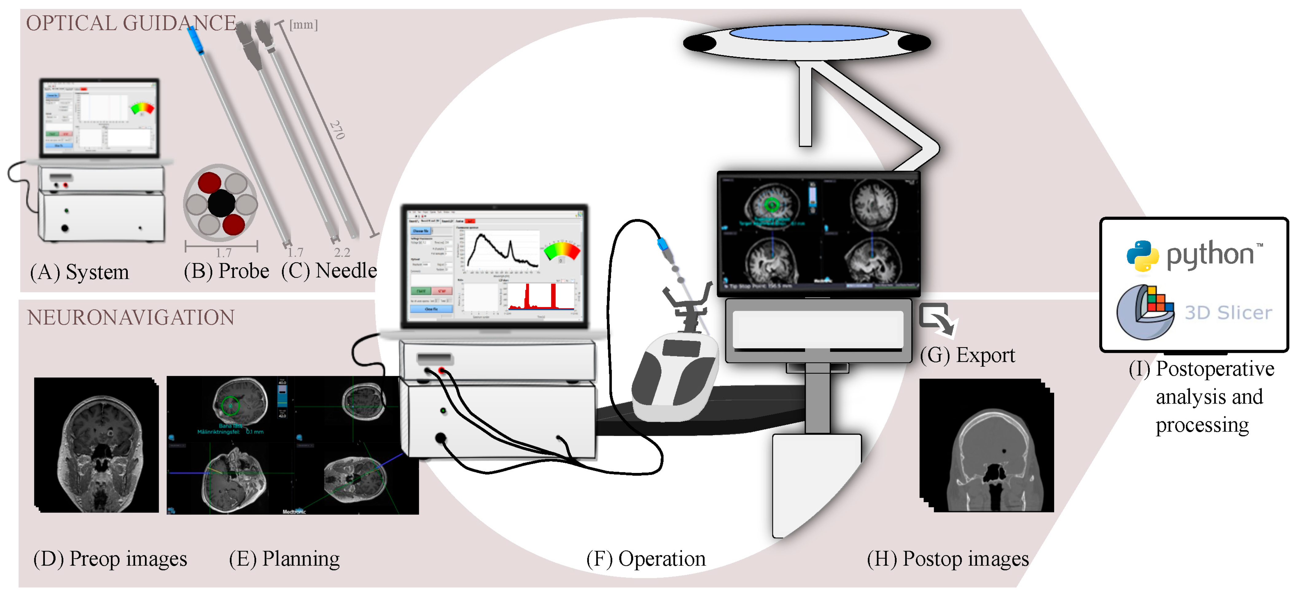
2.1. Optical Guidance

2.1.1. System Development

An in-house optical system that was previously described in [27] and that combined LDF (PF 5010, Perimed AB, Stockholm, Sweden) and 5-ALA-induced fluorescence was updated. Briefly, tissue Perfusion (i.e., microvascular blood flow) and total light intensity (TLI, corresponding to gray–white matter changes) were continuously and simultaneously recorded with point-wise tissue fluorescence spectra. The in-house-developed LabView software (2019, National Instruments, Austin, TX, USA) controlled the fluorescence acquisition settings and presented signals in real time. The ratio, R, between tissue autofluorescence (max intensity between wavelengths: (λ) 470–550 nm) and the intensity at 635 nm was calculated [28]. A peak at 635 nm represented protoporphyrin IX (PpIX) accumulation, indicating high-grade tumor tissue. For further details of the system, see Appendix A.

2.1.2. Probe Redesign

A fiber optical probe (∅ 1.7 mm, length: 270 mm, optical fibers: two ∅ 200 μm, numerical aperture (NA): 0.22 and four ∅ 125 μm, NA: 0.37) was designed to fit into the outer cannula of the frameless navigation biopsy needle (∅ 2.2 mm, length: 270 mm, Passive Biopsy Needle Kit, Medtronic Inc., Minneapolis, MN, USA). For each disposable biopsy kit, an aperture was made at the tip of the outer cannula to allow forward-looking tissue measurements. The tips of both the outer cannula and probe were slightly rounded and polished until smooth. It was ascertained that the functional length of the biopsy needle was kept, and the ‘probe-needle kit’ was tested together to ensure that their respective functionalities were intact.

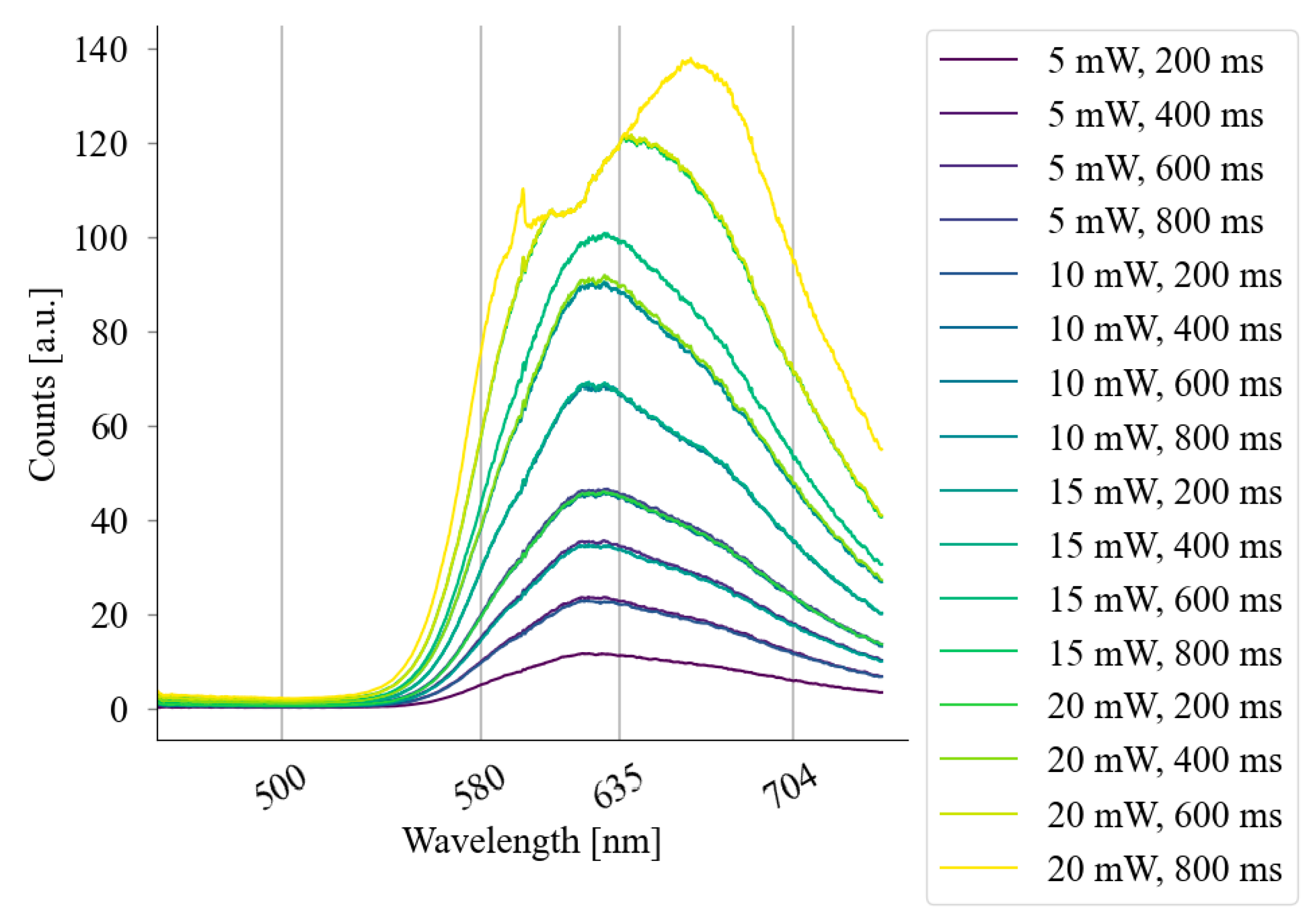
2.1.3. Evaluation of System Dynamics

The fluorescence module was tested for laser powers, P, between 5 and 20 mW, and pulse lengths, PL, of 200, 400, 600, and 800 ms were used to determine the optimal default settings. The evaluation was performed both on a static reference and, as presented in [27], the ventral forearm skin of a healthy volunteer treated with a fluorescent drug (METVIX® 160 mg/g, PhotoCure ASA, Oslo, Norway, Ethics no. M139-07/T83-09) [29]. The LDF signals were tested against a standard microsphere solution (PF1001 Motility, Perimed AB) and on the skin. The simultaneous acquisition was evaluated to investigate the interference between the fluorescence and LDF signals.
Before each use, measurements on the static reference and in the Motility were acquired and checked to determine if they were within acceptable ranges. The probe and the static reference were sterilized according to the Sterrad® protocol.

2.2. Neuronavigation

2.2.1. Image Acquisition

Preoperative magnetic resonance (MR) images were acquired on Siemens 3T scanners (Prisma or Skyra, Siemens Healthineers, Erlangen, Germany). T1-weighted (T1w) images with and without gadolinium (Gd) contrast enhancement, as well as T2w and T2w-FLAIR images, were acquired according to the clinical navigation protocol. The acquisition details of each MR sequence were as follows:
T1w 3D gradient echo before and after Gd (T1wGd) administration: voxel size: 1.0 × 1.0 × 1.0 mm3, FOV: 256 × 176 mm2, tTE = 2.26 ms, tTR = 2300 ms, tTI = 900 ms, GRAPPA 2 (ref lines 24), Gd dose: 16–17 mL (Dotarem, 279 mg/mL);
T2w 3D spin echo: voxel size: 0.9 × 0.9 × 1.0 mm3, FOV: 240 × 176 mm2, tTE = 407 ms, tTR = 3200 ms, GRAPPA 2 (ref lines 24);
T2w-FLAIR 3D spin echo: voxel size: 1.0 × 1.0 × 1.0 mm3, FOV: 256 × 176 mm2, tTE = 388 ms, tTR = 5000 ms, tTI = 1600 ms, GRAPPA 3 (ref lines 24).
Postoperatively, either computed tomography (CT, SOMATOM Definition Edge, Siemens Healthcare, Germany) or T1w 3D MR images (Prisma or Skyra) were acquired to detect potential hemorrhages and confirm the biopsy location. The final biopsy position was defined as the center of the observed cavity.

2.2.2. Frameless Navigation

The preoperative images were downloaded and coregistered on a frameless neuronavigation system (StealthStation S8, Medtronic Inc., USA). The navigation system was also used for trajectory and target planning. Registration between the images and the patient’s physical anatomy was performed by tracing the scalp; then, the trajectory was locked. Errors between the trace and the preoperative images (registration error) and between the locked and planned trajectories (targeting error) were noted. The instruments were held in place by an AutoGuide® (Medtronic Inc., USA). The coordinates of the instruments in the navigation space were logged through the developer mode in the navigation system. Images, metadata, and coordinate points were exported from the navigation system for further analysis in Python.

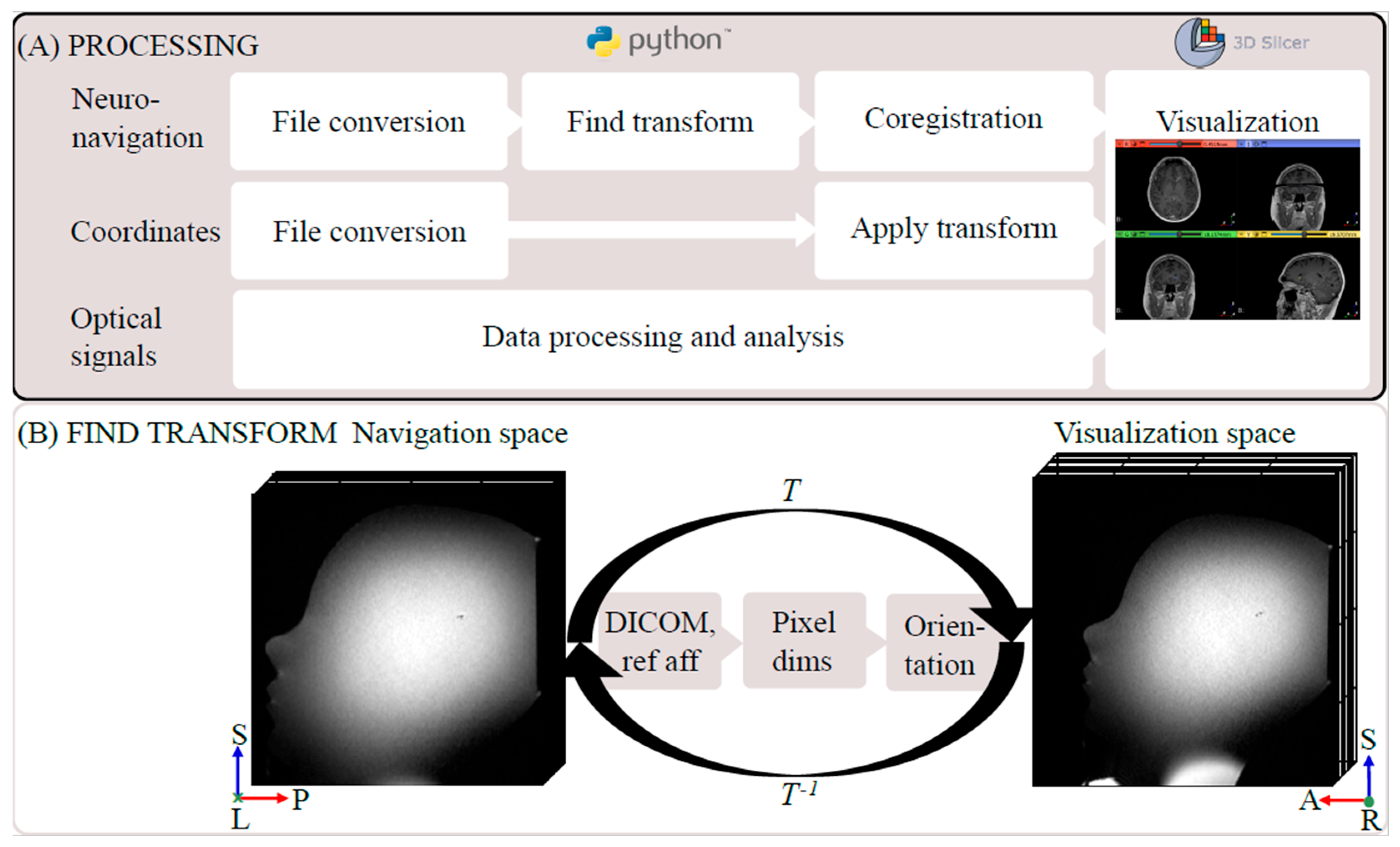
2.2.3. Coordinate Transform and Image Coregistration

The pipeline from the acquired DICOM images to the combined visualization is presented in Figure 2A. In Python (v.3.8), the images were converted to the NIfTI-format by using a wrapper function for dcm2niix [30]. Then, the affine transform, T, was calculated from the navigation—via DICOM—to the visualization space by utilizing the q- and s-form matrices from the DICOM tags. Additionally, other reference spaces in the navigation system were taken into account (e.g., preoperative CT images), and T was corrected for variations in pixel size and coordinate system orientation. The resulting matrix had twelve degrees of freedom of the form
T = r 11 r 12 r 21 r 22 r 13 t x r 23 t y r 31 r 32 0 0 r 33 t z 0 1 ,
where rij (i, j = {1..3}) constitute the linear map (rotation, scaling, and shearing in three spatial dimensions), and tk (k = {x, y, z}) are the translational components (translation in three spatial dimensions). For a schematic illustration of the resulting transform, see Figure 2B.
The pre- and postoperative images were coregistered in Python by using affine linear registration in Advanced Normalization Tools (ANTs) [31] by utilizing the Nipype framework [32]. In the postoperative images, the final entry and biopsy locations were identified by the operating neurosurgeon (J.R.) and transformed into the patient-specific visualization space. Based on these final locations, the preoperative image coordinates of each optical measurement were projected onto the final trajectory by using the Euclidian distance. The final coordinates were superimposed on the preoperative images in the visualization space (3D Slicer, v5.2.1 [33]).

2.2.4. Phantom Evaluation

A low-cost MRI-compatible phantom was constructed by anchoring a ball (∅ 3 mm, mimicking a tumor) in the central region of a plastic head mold. After silicone sealing, the phantom was filled with saline solution, and T1w and T2w 3D MR images were acquired (see the example in Figure 2B). In these images, a trajectory was planned with the ball as the intended target. Registration was performed, the trajectory was locked, and errors were noted. A biopsy needle kit was secured and inserted into the target. Coordinates for points along the trajectory were logged. The procedure—from registration to reaching the target—was repeated three times.
The transformation matrix T was calculated and verified by applying T to both random and unit vector points in the navigation space and comparing the resulting coordinates in the visualization space. The matrix inverse (T1) was used to address the inverse problem.

2.3. Combined Evaluation

The method of frameless MRI-based navigation with optical guidance was implemented in three patients undergoing brain tumor needle biopsies; see the schematic illustration of the clinical workflow in Figure 3.

2.3.1. Patients

Three patients (mean age: 66 years, range: 53–78, one female) planned for frameless needle biopsy at Linköping University Hospital within one month in 2022 were included in the study. The patients had suspected high-grade tumors, as indicated by the contrast enhancement in MRI. This study was carried out in accordance with the Declaration of Helsinki. Study approval was granted by the Swedish Ethical Review Authority (EPM 2020-01404), and written informed consent was obtained from all patients.

2.3.2. Frameless Neuronavigation with Optical Measurements

An oral dose of Gliolan® (20 mg/kg, Medac GmbH, Wedel, Germany, 5-ALA) was given to the patient two to three hours before general anesthesia according to the clinical routine for fluorescence-guided resection [9].
After trajectory planning and registration, a 3.2 mm burr hole was made in the skull, and the dura was opened. Before the investigational optical probe was secured inside the outer cannula of the biopsy needle kit, a functional test on the sterilized static reference was made. The probe–needle kit was fastened to the AutoGuide®, the trajectory was locked, and errors were noted. In situ measurements of brain tissue Perfusion, TLI, and fluorescence were taken in steps of a few millimeters, as indicated in the navigation software, and shown to the surgeon in real time. The probe was held still for 5–15 s at each point to ensure that the LDF measurements were without movement artifacts. If increased Perfusion values were detected, the question of whether to continue or choose another trajectory was posed. The navigation coordinates of each measurement point were logged.
The site with the highest 5-ALA-induced fluorescence peak was identified. If no contraindications were found, the probe–needle kit was adjusted so that the biopsy sampling window coincided with the identified PpIX peak site. Then, the probe was replaced by the inner cannula of the biopsy needle, and the tissue was sampled and sent for a routine intraoperative smear. The patient was prepared for the end of surgery, and the waiting time from tissue sampling to a response from the clinical pathologist was noted.
Within two weeks of surgery, a final diagnosis was given according to the CNS WHO 2021 classification [34].

2.3.3. Postoperative Analysis and Visualization

The mean and standard deviation of the Perfusion and TLI signals for each measurement position were calculated over 5–10 s intervals. Additionally, the fluorescence spectra and R were plotted along the trajectory.
The transform T was calculated and applied to the navigation coordinates. The coregistered images, analyzed optical signals, pre- and postoperative needle biopsy trajectories, and transformed coordinates were imported into 3D Slicer (Figure 2A). The results of the coregistration were visually assessed by the operating neurosurgeon. The Euclidian distance between the pre- and postoperative coordinate points in the coregistered images was calculated.

3. Results

The optical and navigation subsystems were evaluated separately on the references, skin, and a phantom. Then, the combined use of frameless MRI-based neuronavigation and in situ optical feedback was successfully evaluated in the three patient cases. An overview of the proposed clinical workflow can be seen in Figure 3. The postprocessing pipeline (Figure 2A) from DICOM images to combined visualization took approximately 30 min and was automated.

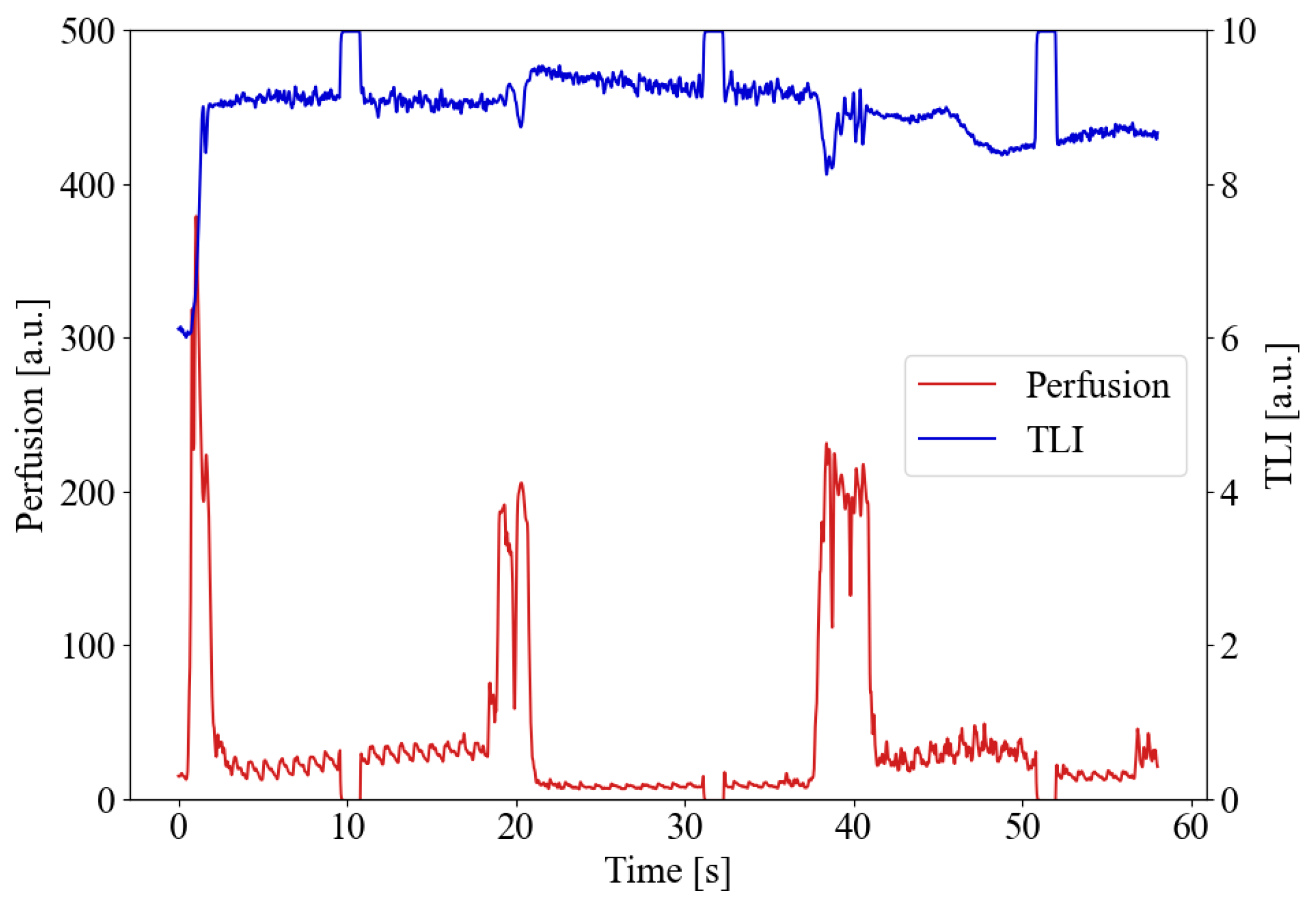
3.1. Optical System Dynamics

The fluorescence and LDF signals on the static reference, skin, and Motility were found to be within acceptable bounds. For the fluorescence, the counts varied from none to a saturated detector for P = 5–20 mW and PL = 200–800 ms. To minimize photobleaching while maintaining a suitable excitation energy and maximizing the use of system dynamics, the default settings were 10 mW and 400 ms (Appendix A, Figure A1). The fluorescence signal was unaffected by the LDF laser due to a cut-off filter. However, transient pulses (3 × PL, default: 1.2 s) were seen in the LDF signal when the fluorescence laser was on (Appendix A, Figure A2).

3.2. Phantom Neuronavigation and Transform
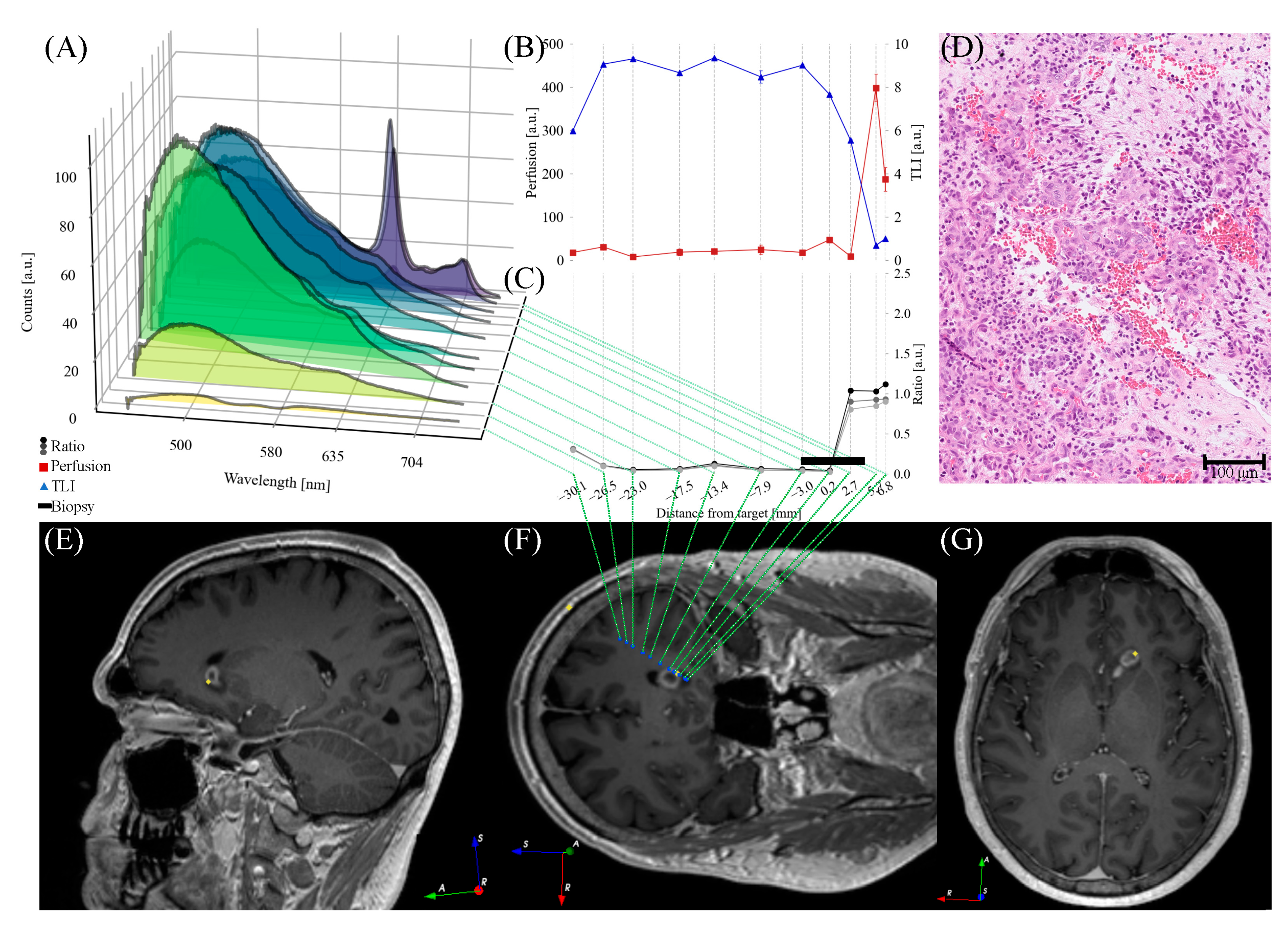
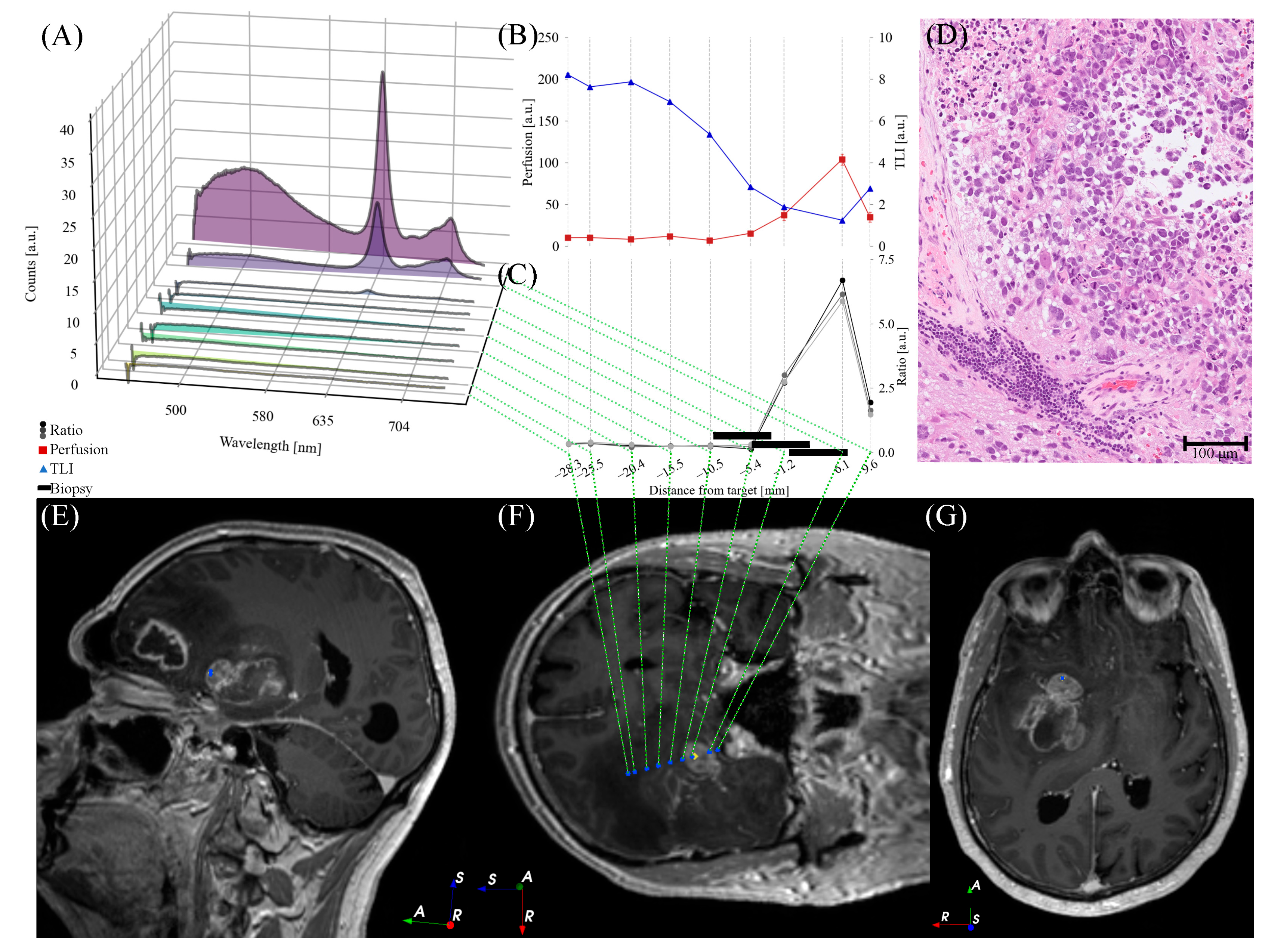
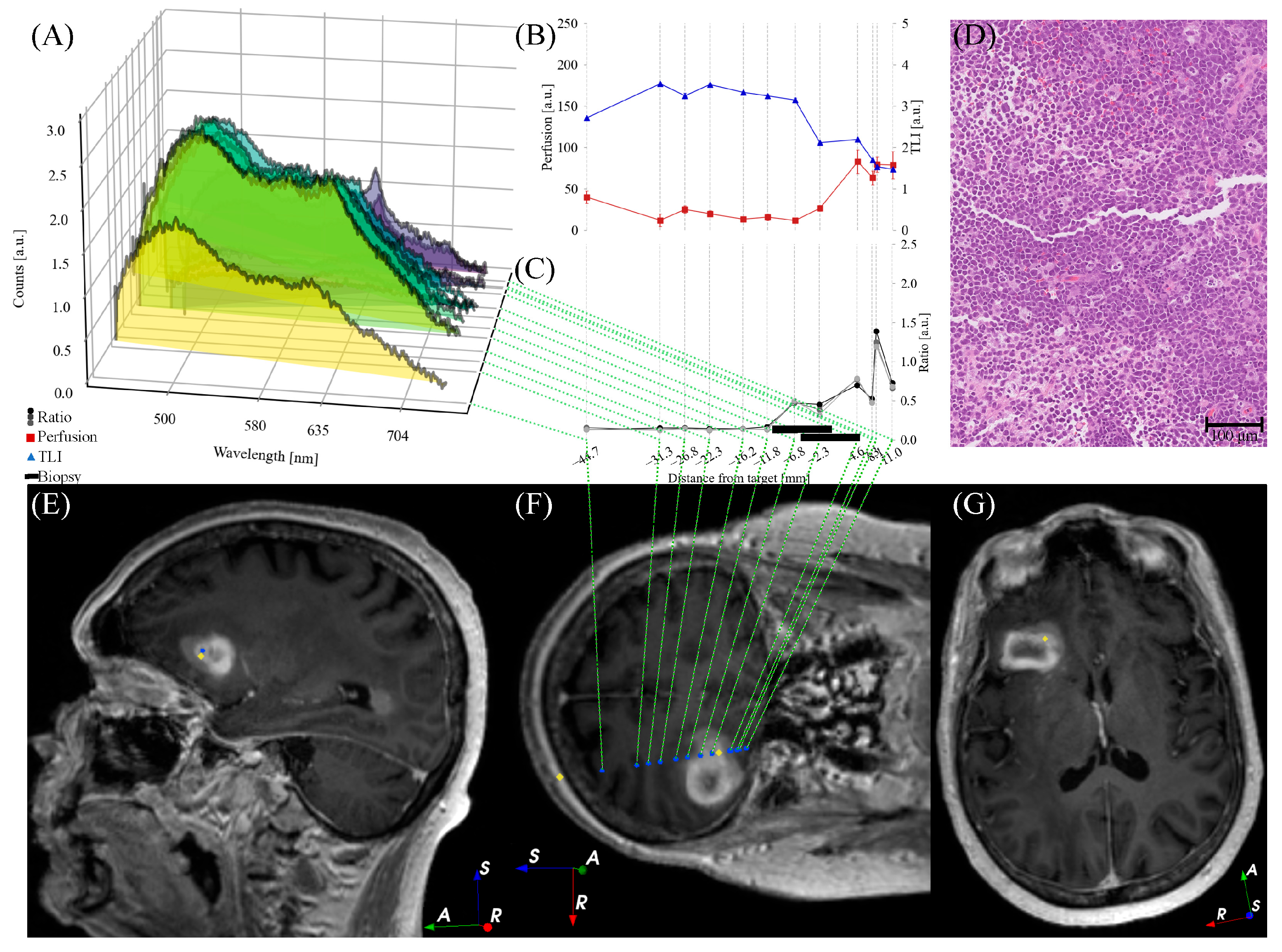
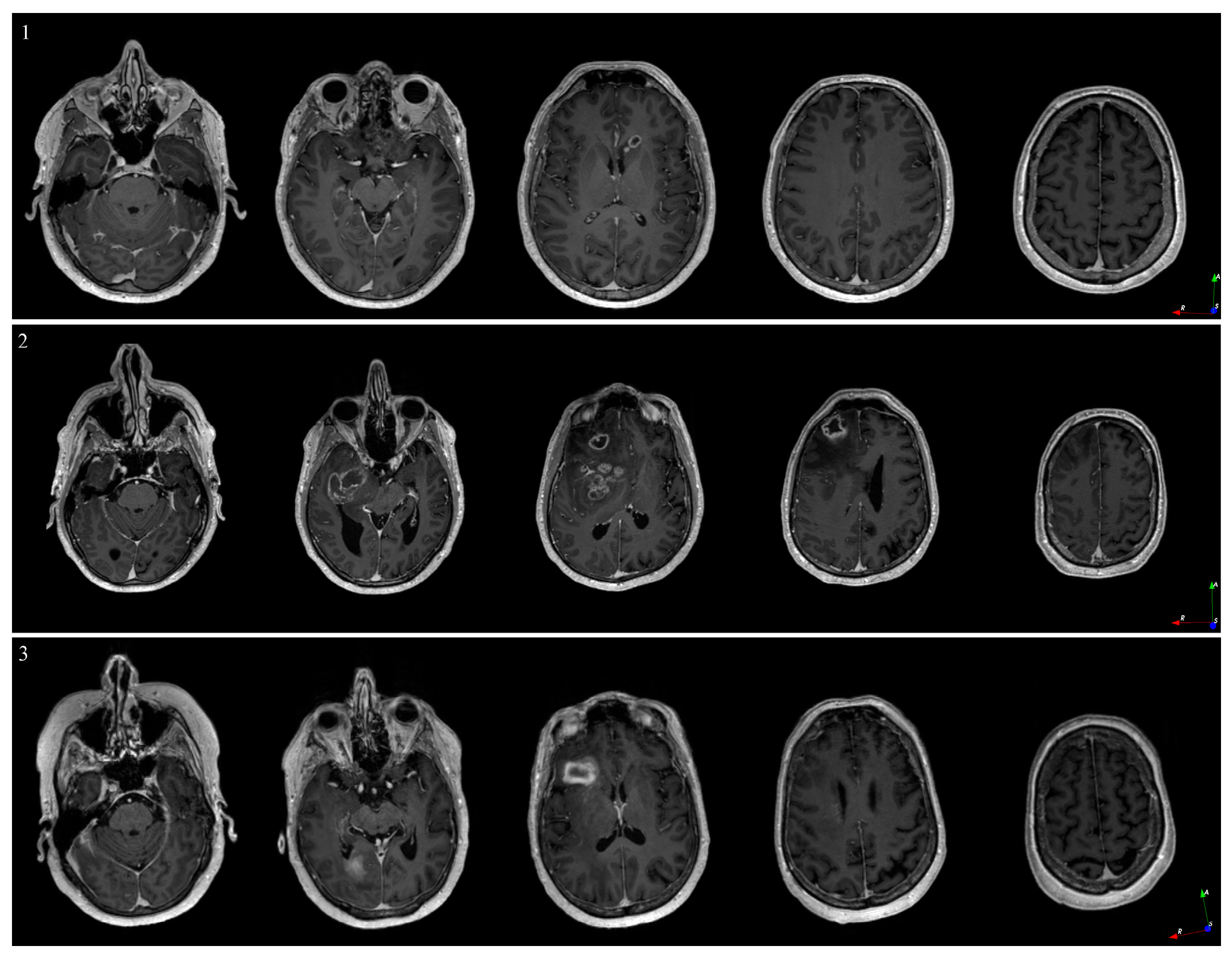
For the three registrations of the in-house phantom, the coordinate points varied by 1.1 ± 0.3 mm between the planned and logged coordinates. The observed errors were 1.4–1.5 mm for registration and 1.1–1.6 mm for targeting. The coordinates are presented in the visualization space in Figure 4.
The predefined points in the navigation and visualization spaces for the phantom showed negligible errors when using the automated transform.

3.3. Patient Cases

Perfusion, TLI, and PpIX fluorescence were presented in situ in 1–14 mm steps along the trajectory, with shorter steps in the target region (Figure 5, Figure 6 and Figure 7). PpIX peaks were found between 1 mm ahead of (Figure 6) and 11 mm beyond (Figure 7) the predefined targets in the preoperative MRI. Biopsy samples were collected in the tissue volume corresponding to the largest peak (Figure 5, Figure 6 and Figure 7A) and ratio (Figure 5, Figure 6 and Figure 7C) without increased Perfusion. A neuropathologist confirmed the samples as tumor tissue within 50–60 min. Increased Perfusion levels (above 100 a.u.) were detected at three points (Figure 5B and Figure 6B), but neither was high enough to result in a trajectory change.
The registration errors were 1.5–1.9 mm and the trajectory targeting errors were 0.1–0.5 mm. For additional slice examples of the preoperative navigation images, see Figure A3 in Appendix B. The default settings for the optical system were used, except for one patient in whom P was increased to 15 mW due to the consistently low fluorescence signals (Figure 7A). The total duration of the functional tests, optical measurements, and annotations was 7–9 min.
Postoperative CT or MR images were acquired within 12 h of surgery. The images confirmed the biopsy sample locations and did not indicate any hemorrhages. The final CNS WHO 2021 diagnoses and grades can be found in Table 1, along with other patient-specific details. For examples of hematoxylin- and eosin-stained histological images, see Figure 5, Figure 6 and Figure 7D.
The combined visualization illustrated the final coordinate points and indicated a shift of 2.5 ± 1.2 mm between the pre- and postoperative locations.

4. Discussion

An investigational one-insertion optical probe system integrated into the frameless MRI-based neuronavigation brain tumor needle biopsy procedure was presented. This translation toward clinical use allows real-time optical feedback while minimizing the number of insertions. To increase the understanding and interconnection between the modalities, the coordinates of the optical measurements were collected and mapped to the corresponding points in the pre- and postoperative images. The automated pipeline for postoperative analysis allows combined visualization of multiparametric data. The methodology offers benefits such as in situ measurements of tissue characteristics before sampling and postoperative visualization for multiparametric analysis. To our knowledge, no other study has combined optical signals, intraoperative MR coordinates, postoperative imaging, and neuropathological results to achieve intraoperative real-time feedback and support postoperative evaluation and verification with the resolution presented herein.
Figure 5, Figure 6 and Figure 7 illustrate the heterogeneity in the task at hand. Variations are seen both within patients (e.g., autofluorescence intensity at different positions) and between patients (e.g., the overall shape of the measured fluorescence response, Figure 5, Figure 6 and Figure 7A). This is also seen in the varying fluorescence ratios (Figure 5, Figure 6 and Figure 7C) and the neuropathological images (Figure 5, Figure 6 and Figure 7D). As the tissue fluorescence and Perfusion values are presented in arbitrary units, further comparison between the patients is discouraged. The overall shapes of the TLI curve (Figure 5, Figure 6 and Figure 7B) are similar as the probe-needle kit goes through the cortex and white matter (slightly brighter, i.e., higher TLI values) and reaches tumor tissue (darker, i.e., lower TLI values).
The overall goal of the needle biopsy procedure is to pose a diagnosis for tailoring further treatment. Thus, in cases in which the neurosurgeon determined the tissue material in the first biopsy position to be insufficient in terms of volume, the needle was moved to a new position, and additional tissue material was sampled.

4.1. In Situ Optical Feedback on Tissue Characteristics

4.1.1. Indication of Tumor Tissue

PpIX fluorescence shows selective accumulation in neoplastic cells [35] and is routinely used during resection for the identification of high-grade tumor tissue [9,10,36] and lymphomas [37,38]. Accumulation has also been indicated for meningiomas [39,40,41] and metastases [36,42,43]. If no PpIX fluorescence peak is registered, tissue collection falls back to the standard method that relies on preoperative images, and increased Perfusion and TLI are still reported.
Other groups have also suggested methods for intraoperative feedback of tissue [11,12,13,14,44,45]. These techniques aim to replace intraoperative pathology through optical feedback, but as the tissue is placed under the microscope after it has been sampled, further benefits are to be gained. A probe system, such as the one presented here, allows for in situ feedback in millimeter steps before the tissue is sampled, both in the sampling position and along the needle trajectory. Other optical markers have been explored. For example, Desroches et al. introduced a Raman probe for measurements in vivo [46]. Raman spectroscopy is a label-free technique based on the molecular vibrations of the tissue with the potential for differentiating tumor and non-tumor tissue [47,48,49]. However, the signals require extensive processing and interpretation, thus currently limiting their intraoperative clinical pertinence. In addition, NaF has been suggested for visualizing tumor tissue [8,14]. The cost of NaF is often mentioned as the main advantage of NaF compared to 5-ALA; however, as Millesi et al. stated, in-house pharmaceutical production of 5-ALA markedly decreases these costs [12].
So far, the probe system introduced in this study has been adapted for the StealthStation and 5-ALA, but it can be modified to fit other setups. Modifying the probe dimensions allows for integration with the LSS frame [19] and use during tumor resection [50].

4.1.2. Addressing the Risk of Hemorrhage

During the biopsy procedure, hemorrhage can occur either when the biopsy needle kit is pushed along the trajectory or when the needle cuts the tissue during sampling. Even though the overall risk of hemorrhage is difficult to eliminate, increased Perfusion can indicate areas in which to take extra care and those that should be avoided altogether. In one patient, increased Perfusion coincided with a clear PpIX peak, indicating that this point (~6 mm beyond the preoperative target, Figure 5B) was likely tumor tissue, but should still be avoided to decrease the risk of hemorrhage.
Both Wilson et al. [51] and Ramakonar et al. [52] illustrated the potential to detect blood vessels through the side-cutting window of a biopsy needle by using optical spectroscopy and optical coherence tomography probes, respectively. These probes do not, however, address the microcirculation during insertion.

4.2. Navigation in Neurosurgery

MRI-based navigation enables planning and feedback, which are crucial to the procedure. However, one could argue that the images are obsolete at the moment in which the patient is moved from the MR scanner due to, e.g., changed head position, intubation, and fluid regulation. Even in the phantom simulation, though movement during image acquisition, brain shift, and tumor growth were eradicated, a discrepancy was observed in the resulting coordinate points for the three registrations. This discrepancy was most likely due to errors in registration and targeting, which was supported by their order of magnitude. Other studies reported errors in the range of 0.1–3.3 mm [53,54], which corroborated our findings for both the phantom and patient cases. In the patient cases, the discrepancy between the pre- and postoperative positions was most likely a combination of registration and targeting errors, condition changes, including brain shifts and fluid leakage between imaging and operation, and interpolations made during image registration and transform calculation. Therefore, we stress the importance of using postoperative images to verify the actual trajectory used during the procedure, especially in the interest of the comparison of modalities. Further, as additional MRI sequences, such as quantitative MRI, are developed to aid in planning, it is important to keep this misalignment in mind.
Other groups have illuminated the benefit of combining 5-ALA-induced fluorescence and MRI. For example, Giordano et al. [44] and Roberts et al. [55] compared contrast enhancement in intraoperative and preoperative MRI, respectively, with fluorescence under a blue light microscope during resection. Both studies found a strong relationship between fluorescence and contrast enhancement.

4.3. Limitations and Outlook

The different modalities used herein present data with different resolutions. For example, the MR protocol specifies isotropic 1 mm3 voxels, a navigation system with submillimeter precision, optical measurements with an approximate 1 mm look-ahead distance [56,57], and a biopsy needle window of 8 mm in length; neuropathology is performed on submillimeter tissue sections. With changing conditions and varying registration errors reported in the literature, the final resolution should be stated with caution.
To evaluate the methodology further, a larger patient cohort is needed. Hence, no conclusions were drawn regarding the mean registration error, size of the brain shift, shortened procedure time, or reduction in the associated risks. Therefore, currently, more data are being collected to analyze these parameters in a follow-up study. Present investigations also include the potential of other MRI sequences for giving feedback on the tissue microstructure.

5. Conclusions

In conclusion, the presented in situ optical guidance method gives feedback on the tissue along the biopsy’s trajectory before the tissue is removed. The quantified optical signals represent the tissue microcirculation, gray–whiteness, and PpIX accumulation. Integration into the frameless MRI-based needle biopsy procedure allows further postoperative analysis by relating the signals to coordinates in the pre- and postoperative images.

Author Contributions

Conceptualization, K.W.; methodology, E.K., J.R. and K.W.; software, E.K.; validation, E.K.; formal analysis, E.K.; investigation, E.K., J.R. and K.W.; resources, K.W.; data curation, E.K.; writing—original draft preparation, E.K. and K.W.; writing—review and editing, E.K., J.R. and K.W.; visualization, E.K.; supervision, J.R. and K.W.; project administration, K.W.; funding acquisition, K.W. All authors have read and agreed to the published version of the manuscript.

Funding

This project was financially supported by the Swedish Foundation for Strategic Research (grant number RMX18-0056).

Institutional Review Board Statement

The study was conducted in accordance with the Declaration of Helsinki and approved by the Local Ethics Committee (EPM-2020-01404).

Informed Consent Statement

Written informed consent was obtained from the patients to publish this paper.

Data Availability Statement

The data are not publicly available due to privacy regulations.

Acknowledgments

The authors would like to thank Bengt Ragnemalm (Department of Biomedical Engineering) for the probe construction, Anders Tisell (Department of Radiation Physics) for MRI expertise, Peter Milos and Alexandros Apostolou (Department of Neurosurgery) for assisting in surgery, and Martin Hallbeck (Department of Clinical Pathology) for the complementary neuropathological analysis. The authors are also grateful to the clinical staff at the Departments of Neurosurgery and Clinical Pathology at Linköping University Hospital.

Conflicts of Interest

Karin Wårdell and Johan Richter hold shares in a university spin-off company, FluoLink AB, Sweden. The funders had no role in the design of the study, in the collection, analyses, or interpretation of data, in the writing of the manuscript, or in the decision to publish the results.

Appendix A

Optical Measurement System
The dual-laser optics system presented in this study consisted of a commercial LDF unit (λ = 780 nm, P = 2 mW, PF 5010, Perimed AB, Sweden) and a fluorescence module that was constructed in-house. The fluorescence module consisted of a near-UV laser (λ = 405 nm, ≤40 mW, Z-laser GmbH, Germany) and a CCD spectrometer (AVASpect-ULS2048L-EVO, Avantes, BV, The Netherlands). Wavelength calibration was carried out for the spectrometer. The two modules were linked through a data acquisition (DAQ) card (NI USB-6211, Nation Instruments, Austin, TX, USA).
A bandpass filter (long-pass, cut-on: λ = 455 nm, Newport, Newport Corporation, USA, and short-pass, cut-off: λ = 750 nm, Edmund Optics, Edmund Optics Inc., Barrington, NJ, USA) blocked the Rayleigh scattered light from the incident laser beams from reaching the spectrometer.
Signal Acquisition
Each fluorescence measurement consisted of one dark spectrum (laser off) followed by three light spectra (laser on). The dark spectrum was subtracted from each light spectrum to remove the influence from the surrounding light.
The fluorescence acquisition settings could be set to laser powers between P = 5 and 20 mW; the pulse lengths were PL = 50–1000 ms, and there were 1–1000 spectra within the wavelength interval λ of 450–750 nm. The default settings were 10 mW and 400 ms (Figure A1), resulting in an excitation energy of 4 mJ. The optional settings included auditory feedback as the ratio R exceeded a user-specified threshold. The heart rate could be calculated from the small pulses in the Perfusion signal (Figure A2).
Figure A1. Fluorescence counts for various laser powers (5–20 mW) and pulse lengths (200–800 ms) against a static reference.
Brainsci 13 00809 g0a1
Figure A2. Perfusion and TLI signals from three measurement points recorded on brain tissue. The large (200–400 counts) irregular spikes are artifacts caused when moving the probe from one position to the next. The square features (occurring around 10, 32, and 52 s) were caused by the fluorescence acquisition, namely, when the near-UV laser was on.
Brainsci 13 00809 g0a2

Appendix B

Imaging in Neurosurgery
Figure A3. Sample image slices from the T1wGd image volume used for neuronavigation for patient 1 (top), 2 (middle), and 3 (bottom). Image orientation R: right, A: anterior, S: superior.
Brainsci 13 00809 g0a3

References

  1. Azagury, D.E.; Dua, M.M.; Barrese, J.C.; Henderson, J.M.; Buchs, N.C.; Ris, F.; Cloyd, J.M.; Martinie, J.B.; Razzaque, S.; Nicolau, S.; et al. Image-Guided Surgery. Curr. Probl. Surg. 2015, 52, 476–520. [Google Scholar] [CrossRef] [PubMed]
  2. Miner, R.C. Image-Guided Neurosurgery. J. Med. Imaging Radiat. Sci. 2017, 48, 328–335. [Google Scholar] [CrossRef]
  3. Wang, M.N.; Song, Z.J. Classification and Analysis of the Errors in Neuronavigation. Neurosurgery 2011, 68, 1131–1143. [Google Scholar] [CrossRef] [PubMed]
  4. Kongkham, P.N.; Knifed, E.; Tamber, M.S.; Bernstein, M. Complications in 622 Cases of Frame-Based Stereotactic Biopsy, a Decreasing Procedure. Can. J. Neurol. Sci. 2008, 35, 79–84. [Google Scholar] [CrossRef] [PubMed]
  5. Riche, M.; Amelot, A.; Peyre, M.; Capelle, L.; Carpentier, A.; Mathon, B. Complications after Frame-Based Stereotactic Brain Biopsy: A Systematic Review. Neurosurg. Rev. 2021, 44, 301–307. [Google Scholar] [CrossRef]
  6. Khatab, S.; Spliet, W.; Woerdeman, P.A. Frameless Image-Guided Stereotactic Brain Biopsies: Emphasis on Diagnostic Yield. Acta Neurochir. (Wien) 2014, 156, 1441–1450. [Google Scholar] [CrossRef]
  7. Livermore, L.J.; Ma, R.; Bojanic, S.; Pereira, E.A. Yield and Complications of Frame-Based and Frameless Stereotactic Brain Biopsy—The Value of Intra-Operative Histological Analysis. Br. J. NeuroSurg. 2014, 28, 637–644. [Google Scholar] [CrossRef]
  8. Acerbi, F.; Broggi, M.; Eoli, M.; Anghileri, E.; Cuppini, L.; Pollo, B.; Schiariti, M.; Visintini, S.; Orsi, C.; Franzini, A.; et al. Fluorescein-Guided Surgery for Grade Iv Gliomas with a Dedicated Filter on the Surgical Microscope: Preliminary Results in 12 Cases. Acta Neurochir. (Wien) 2013, 155, 1277–1286. [Google Scholar] [CrossRef]
  9. Hadjipanayis; Constantinos, G.; Stummer, W. 5-Ala and Fda Approval for Glioma Surgery. J. Neuro-Oncol. 2019, 141, 479–486. [Google Scholar] [CrossRef]
  10. Stummer, W.; Pichlmeier, U.; Meinel, T.; Wiestler, O.D.; Zanella, F.; Reulen, H.-J. Fluorescence-Guided Surgery with 5-Aminolevulinic Acid for Resection of Malignant Glioma: A Randomised Controlled Multicentre Phase Iii Trial. Lancet Oncol. 2006, 7, 392–401. [Google Scholar] [CrossRef]
  11. von Campe, G.; Moschopulos, M.; Hefti, M. 5-Aminolevulinic Acid-Induced Protoporphyrin Ix Fluorescence as Immediate Intraoperative Indicator to Improve the Safety of Malignant or High-Grade Brain Tumor Diagnosis in Frameless Stereotactic Biopsies. Acta Neurochir. (Wien) 2012, 154, 585–588. [Google Scholar] [CrossRef]
  12. Millesi, M.; Kiesel, B.; Wöhrer, A.; Mercea, P.A.; Bissolo, M.; Roetzer, T.; Wolfsberger, S.; Furtner, J.; Knosp, E.; Widhalm, G. Is Intraoperative Pathology Needed If 5-Aminolevulinic-Acid-Induced Tissue Fluorescence Is Found in Stereotactic Brain Tumor Biopsy? Neurosurgery 2020, 86, 366–373. [Google Scholar] [CrossRef] [PubMed]
  13. Bianco, A.; Del Maestro, M.; Fanti, A.; Airoldi, C.; Fleetwood, T.; Crobeddu, E.; Cossandi, C. Use of Fluorescein Sodium–Assisted Intraoperative Sample Validation to Maximize the Diagnostic Yield of Stereotactic Brain Biopsy: Progress toward a New Standard of Care? J. Neurosurg. 2023, 138, 358–366. [Google Scholar] [CrossRef] [PubMed]
  14. Thien, A.; Han, J.X.; Kumar, K.; Ng, Y.P.; Rao, J.P.; Ng, W.H.; King, N.K.K. Investigation of the Usefulness of Fluorescein Sodium Fluorescence in Stereotactic Brain Biopsy. Acta Neurochir. (Wien) 2018, 160, 317–324. [Google Scholar] [CrossRef] [PubMed]
  15. Haj-Hosseini, N.; Richter, J.C.O.; Milos, P.; Hallbeck, M.; Wårdell, K. 5-Ala Fluorescence and Laser Doppler Flowmetry for Guidance in a Stereotactic Brain Tumor Biopsy. BioMed. Opt. Express 2018, 9, 2284–2296. [Google Scholar] [CrossRef]
  16. Wårdell, K.; Zsigmond, P.; Richter, J.; Hemm, S. Relationship between Laser Doppler Signals and Anatomy During Deep Brain Stimulation Electrode Implantation toward the Ventral Intermediate Nucleus and Subthalamic Nucleus. Neurosurgery 2013, 72, ons127-40. [Google Scholar] [CrossRef]
  17. Zsigmond, P.; Hemm-Ode, S.; Wårdell, K. Optical Measurements During Deep Brain Stimulation Lead Implantation: Safety Aspects. Ster. Funct. NeuroSurg. 2017, 95, 392–399. [Google Scholar] [CrossRef]
  18. Richter, J.; Haj-Hosseini, N.; Milos, P.; Hallbeck, M.; Wårdell, K. Optical Brain Biopsy with a Fluorescence and Vessel Tracing Probe. Oper. NeuroSurg. (Hagerstown) 2021, 21, 217–224. [Google Scholar] [CrossRef]
  19. Wårdell, K.; Klint, E.; Milos, P.; Richter, J. One-Insertion Stereotactic Brain Biopsy Using in-Vivo Optical Guidance—A Case Study. Oper. NeuroSurg. (Hagerstown) 2023. [Google Scholar] [CrossRef]
  20. Georgiopoulos, M.; Ellul, J.; Chroni, E.; Constantoyannis, C. Efficacy, Safety, and Duration of a Frameless Fiducial-Less Brain Biopsy Versus Frame-Based Stereotactic Biopsy: A Prospective Randomized Study. J. Neurol. Surg. A Cent. Eur. NeuroSurg. 2018, 79, 31–38. [Google Scholar]
  21. Kesserwan, M.A.; Shakil, H.; Lannon, M.; McGinn, R.; Banfield, L.; Nath, S.; Alotaibi, M.; Kasper, E.; Sharma, S. Frame-Based Versus Frameless Stereotactic Brain Biopsies: A Systematic Review and Meta-Analysis. Surg. Neurol. Int. 2021, 12, 52. [Google Scholar] [CrossRef] [PubMed]
  22. Ungar, L.; Nachum, O.; Zibly, Z.; Wohl, A.; Harel, R.; Attia, M.; Spiegelmann, R.; Zaubermann, J.; Feldman, Z.; Knoller, N.; et al. Comparison of Frame-Based Versus Frameless Image-Guided Intracranial Stereotactic Brain Biopsy: A Retrospective Analysis of Safety and Efficacy. World NeuroSurg. 2022, 164, e1–e7. [Google Scholar] [CrossRef] [PubMed]
  23. Dhawan, S.; He, Y.; Bartek, J.; Alattar, A.A.; Chen, C.C. Comparison of Frame-Based Versus Frameless Intracranial Stereotactic Biopsy: Systematic Review and Meta-Analysis. World Neurosurg. 2019, 127, 607–616.e4. [Google Scholar] [CrossRef]
  24. Vychopen, M.; Wach, J.; Borger, V.; Schneider, M.; Eichhorn, L.; Maciaczyk, J.; Bara, G.; Vatter, H.; Banat, M.; Hamed, M. Patient Safety Comparison of Frameless and Frame-Based Stereotactic Navigation for Brain Biopsy—A Single Center Cohort Study. Brain Sci. 2022, 12, 1178. [Google Scholar] [CrossRef]
  25. Dorward, N.L.; Paleologos, T.S.; Alberti, O.; Thomas, D.G.T. The Advantages of Frameless Stereotactic Biopsy over Frame-Based Biopsy. Br. J. Neurosurg. 2002, 16, 110–118. [Google Scholar] [CrossRef] [PubMed]
  26. Sciortino, T.; Fernandes, B.; Nibali, M.C.; Gay, L.G.; Rossi, M.; Lopci, E.; Colombo, A.E.; Elefante, M.G.; Pessina, F.; Bello, L.; et al. Frameless Stereotactic Biopsy for Precision Neurosurgery: Diagnostic Value, Safety, and Accuracy. Acta Neurochir. 2019, 161, 967–974. [Google Scholar] [CrossRef] [PubMed]
  27. Klint, E.; Mauritzon, S.; Ragnemalm, B.; Richter, J.; Wårdell, K. Fluora—A System for Combined Fluorescence and Microcirculation Measurements in Brain Tumor Surgery. Annu. Int. Conf. IEEE Eng. Med. Biol. Soc. 2021, 2021, 1512–1515. [Google Scholar]
  28. Bendsoe, N.; Persson, L.; Johansson, A.; Axelsson, J.; Svensson, J.; Gräfe, S.; Trebst, T.; Andersson-Engels, S.; Svanberg, S.; Svanberg, K. Fluorescence Monitoring of a Topically Applied Liposomal Temoporfin Formulation and Photodynamic Therapy of Nonpigmented Skin Malignancies. J. Environ. Pathol. Toxicol. Oncol. 2007, 26, 117–126. [Google Scholar] [CrossRef]
  29. Manifold, R.; Anderson, C. Increased Cutaneous Oxygen Availability by Topical Application of Hydrogen Peroxide Cream Enhances the Photodynamic Reaction to Topical 5-Aminolevulinic Acid-Methyl Ester. Arch. Dermatol. Res. 2011, 303, 285–292. [Google Scholar] [CrossRef]
  30. Li, X.; Morgan, P.S.; Ashburner, J.; Smith, J.; Rorden, C. The First Step for Neuroimaging Data Analysis: Dicom to Nifti Conversion. J. Neurosci. Methods 2016, 264, 47–56. [Google Scholar] [CrossRef]
  31. Tustison, N.J.; Avants, B.B.; Cook, P.A.; Zheng, Y.; Egan, A.; Yushkevich, P.A.; Gee, J.C. N4itk: Improved N3 Bias Correction. IEEE Trans. Med. Imaging 2010, 29, 1310–1320. [Google Scholar] [CrossRef] [PubMed]
  32. Gorgolewski, K.; Burns, C.; Madison, C.; Clark, D.; Halchenko, Y.; Waskom, M.; Ghosh, S. Nipype: A Flexible, Lightweight and Extensible Neuroimaging Data Processing Framework in Python. Front. Neuroinformatics 2011, 5, 13. [Google Scholar] [CrossRef] [PubMed]
  33. Fedorov, A.; Beichel, R.; Kalpathy-Cramer, J.; Finet, J.; Fillion-Robin, J.-C.; Pujol, S.; Bauer, C.; Jennings, D.; Fennessy, F.; Sonka, M.; et al. 3d Slicer as an Image Computing Platform for the Quantitative Imaging Network. Magn. Reson. Imaging 2012, 30, 1323–1341. [Google Scholar] [CrossRef]
  34. WHO. Classification of Tumours Editorial Board. In Central Nervous System Tumours, 5th ed.; Who Classification of Tumours Series; International Agency for Research on Cancer: Lyon, France, 2021; Volume 6. [Google Scholar]
  35. Collaud, S.; Juzeniene, A.; Moan, J.; Lange, N. On the Selectivity of 5-Aminolevulinic Acid-Induced Protoporphyrin Ix Formation. Curr. Med. Chem Anticancer Agents 2004, 4, 301–316. [Google Scholar] [CrossRef]
  36. Hefti, M.; von Campe, G.; Moschopulos, M.; Siegner, A.; Looser, H.; Landolt, H. 5-Aminolevulinic Acid Induced Protoporphyrin Ix Fluorescence in High-Grade Glioma Surgery: A One-Year Experience at a Single Institutuion. Swiss Med. Wkly. 2008, 138, 180–185. [Google Scholar] [PubMed]
  37. Evers, G.; Kamp, M.; Warneke, N.; Berdel, W.; Sabel, M.; Stummer, W.; Ewelt, C. 5-Aminolaevulinic Acid-Induced Fluorescence in Primary Central Nervous System Lymphoma. World NeuroSurg. 2017, 98, 375–380. [Google Scholar] [CrossRef] [PubMed]
  38. Kiesel, B.; Millesi, M.; Woehrer, A.; Furtner, J.; Bavand, A.; Roetzer, T.; Mischkulnig, M.; Wolfsberger, S.; Preusser, M.; Knosp, E.; et al. 5-Ala-Induced Fluorescence as a Marker for Diagnostic Tissue in Stereotactic Biopsies of Intracranial Lymphomas: Experience in 41 Patients. NeuroSurg. Focus 2018, 44, E7. [Google Scholar] [CrossRef]
  39. Cornelius, J.F.; Kamp, M.A.; Tortora, A.; Knipps, J.; Krause-Molle, Z.; Beez, T.; Petridis, A.K.; Sabel, M.; Schipper, J.; Steiger, H.J. Surgery of Small Anterior Skull Base Meningiomas by Endoscopic 5-Aminolevulinic Acid Fluorescence Guidance: First Clinical Experience. World NeuroSurg. 2019, 122, e890–e895. [Google Scholar] [CrossRef]
  40. Millesi, M.; Kiesel, B.; Mischkulnig, M.; Martínez-Moreno, M.; Wöhrer, A.; Wolfsberger, S.; Knosp, E.; Widhalm, G. Analysis of the Surgical Benefits of 5-Ala-Induced Fluorescence in Intracranial Meningiomas: Experience in 204 Meningiomas. J. NeuroSurg. 2016, 125, 1408–1419. [Google Scholar] [CrossRef]
  41. Valdes, P.A.; Millesi, M.; Widhalm, G.; Roberts, D.W. 5-Aminolevulinic Acid Induced Protoporphyrin Ix (Ala-Ppix) Fluorescence Guidance in Meningioma Surgery. J. Neuro-Oncol. 2019, 141, 555–565. [Google Scholar] [CrossRef]
  42. Eljamel, M.S. Fluorescence Image-Guided Surgery of Brain Tumors: Explained Step-by-Step. Photodiagnosis Photodyn 2008, 5, 260–263. [Google Scholar] [CrossRef] [PubMed]
  43. Knipps, J.; Fischer, I.; Neumann, L.M.; Rapp, M.; Dibué-Adjei, M.; von Saß, C.F.; Placke, J.-M.; Mijderwijk, H.-J.; Steiger, H.-J.; Sabel, M.; et al. Quantification of Ppix-Fluorescence of Cerebral Metastases: A Pilot Study. Clin. Exp. Metastasis 2019, 36, 467–475. [Google Scholar] [CrossRef] [PubMed]
  44. Giordano, M.; Gallieni, M.; Zaed, I.; Samii, A. Use of Frameless Stereotactic Navigation System Combined with Intraoperative Magnetic Resonance Imaging and 5-Aminolevulinic Acid. World Neurosurg. 2019, 131, 32–37. [Google Scholar] [CrossRef] [PubMed]
  45. Shofty, B.; Richetta, C.; Haim, O.; Kashanian, A.; Gurevich, A.; Grossman, R. 5-Ala-Assisted Stereotactic Brain Tumor Biopsy Improve Diagnostic Yield. Eur J. Surg. Oncol 2019, 45, 2375–2378. [Google Scholar] [CrossRef] [PubMed]
  46. Desroches, J.; Lemoine, É.; Pinto, M.; Marple, E.; Urmey, K.; Diaz, R.; Guiot, M.C.; Wilson, B.C.; Petrecca, K.; Leblond, F. Development and First in-Human Use of a Raman Spectroscopy Guidance System Integrated with a Brain Biopsy Needle. J. Biophotonics 2019, 12, e201800396. [Google Scholar] [CrossRef]
  47. Anna, I.; Bartosz, P.; Lech, P.; Halina, A. Novel Strategies of Raman Imaging for Brain Tumor Research. Oncotarget 2017, 8, 85290–85310. [Google Scholar] [CrossRef]
  48. Livermore, L.J.; Isabelle, M.; Bell, I.M.; Scott, C.; Walsby-Tickle, J.; Gannon, J.; Plaha, P.; Vallance, C.; Ansorge, O. Rapid Intraoperative Molecular Genetic Classification of Gliomas Using Raman Spectroscopy. Neurooncol. Adv. 2019, 1, vdz008. [Google Scholar] [CrossRef]
  49. Wahl, J.; Klint, E.; Hallbeck, M.; Hillman, J.; Wårdell, K.; Ramser, K. Impact of Preprocessing Methods on the Raman Spectra of Brain Tissue. BioMed. Opt. Express 2022, 13, 6763–6777. [Google Scholar] [CrossRef]
  50. Richter, J.C.O.; Haj-Hosseini, N.; Hallbeck, M.; Wårdell, K. Combination of Hand-Held Probe and Microscopy for Fluorescence Guided Surgery in the Brain Tumor Marginal Zone. Photodiagnosis Photodyn 2017, 18, 185–192. [Google Scholar] [CrossRef]
  51. Wilson, B.; Kim, A.; Valdes, P.; Paulsen, K.; Roberts, D. Biopsy Device with Integrated Optical Spectroscopy Guidance. Patent EP2793706A4, 14 October 2015. [Google Scholar]
  52. Ramakonar, H.; Quirk, B.C.; Kirk, R.W.; Li, J.; Jacques, A.; Lind, C.R.P.; McLaughlin, R.A. Intraoperative Detection of Blood Vessels with an Imaging Needle During Neurosurgery in Humans. Sci. Adv. 2018, 4, eaav4992. [Google Scholar] [CrossRef]
  53. Skyrman, S.; Lai, M.; Edström, E.; Burström, G.; Förander, P.; Homan, R.; Kor, F.; Holthuizen, R.; Hendriks, B.H.W.; Persson, O.; et al. Augmented Reality Navigation for Cranial Biopsy and External Ventricular Drain Insertion. NeuroSurg. Focus 2021, 51, E7. [Google Scholar] [CrossRef] [PubMed]
  54. Widmann, G.; Schullian, P.; Ortler, M.; Bale, R. Frameless Stereotactic Targeting Devices: Technical Features, Targeting Errors and Clinical Results. Int. J. Med. Robot 2012, 8, 1–16. [Google Scholar] [CrossRef] [PubMed]
  55. Roberts, D.W.; Valdés, P.A.; Harris, B.T.; Fontaine, K.M.; Hartov, A.; Fan, X.; Ji, S.; Lollis, S.S.; Pogue, B.W.; Leblond, F.; et al. Coregistered Fluorescence-Enhanced Tumor Resection of Malignant Glioma: Relationships between Δ-Aminolevulinic Acid-Induced Protoporphyrin Ix Fluorescence, Magnetic Resonance Imaging Enhancement, and Neuropathological Parameters. Clinical Article. J. NeuroSurg. 2011, 114, 595–603. [Google Scholar] [CrossRef] [PubMed]
  56. Qian, Z.; Victor, S.; Gu, Y.; Giller, C.; Liu, H. Look-Ahead Distance of a Fiber Probe Used to Assist Neurosurgery: Phantom and Monte Carlo Study. Opt. Express 2003, 11, 1844–1855. [Google Scholar] [CrossRef]
  57. Johansson, J.; Fredriksson, I.; Wårdell, K.; Eriksson, O. Simulation of Reflected Light Intensity Changes During Navigation and Radio-Frequency Lesioning in the Brain. J. Biomed. Opt. 2009, 14, 044040. [Google Scholar] [CrossRef]
Figure 1. Block diagram of the methodology. Optical guidance and neuronavigation were evaluated separately before the combined clinical evaluation and postoperative visualization.
Brainsci 13 00809 g001
Figure 2. Processing pipeline including the coordinate transform. (A) Processing pipeline from export to visualization of the images used for neuronavigation, the intraoperative MR coordinates, and the optical signals. (B) Phantom example of the ‘Find transform’ step between the navigation and visualization space, which utilized the DICOM information and took other reference volumes into account. Image orientation R: right, L: left, A: anterior, P: posterior, S: superior. Ref: reference.
Brainsci 13 00809 g002
Figure 3. Clinical workflow for preparation, data acquisition, and export in a clinical setting for frameless MRI-based neuronavigation with in situ optical guidance. (A) An optical measurement system and (B) probe integrated into the (C) modifised biopsy needle were tested and prepared for surgery. (D) Preoperative images were acquired, and (E) trajectory planning was performed before surgery. (F) During operation, optical signals were displayed in real time and navigation coordinates were logged. (G) After the procedure, the images, metadata, and optical signals were exported. (H) Postoperative images were acquired, and finally, (I) analysis was performed for multiparametric visualization.
Brainsci 13 00809 g003
Figure 4. Registration and transformation of three consecutive frameless navigation procedures on a low-cost MRI head phantom. (A) Oblique sagittal, (B) coronal, and (C) axial slices of the T1w image volume. (D) Zoom of the target area in the sagittal view. (AD) Diamonds and lines indicate thepreoperatively planned trajectory, circles indicate the intraoperative measurement points. Image orientation R: right, A: anterior, S: superior.
Brainsci 13 00809 g004
Figure 5. Optical signals ((A) fluorescence spectra, (B) Perfusion and TLI signals, and (C) fluorescence ratio R) for each measurement position along the trajectory for patient 1. (D) Example of an H&E-stained section from the neuropathological analysis. (E) Oblique sagittal, (F) coronal, and (G) axial T1wGd image that is tilted to capture the postoperative trajectory. (EG) Blue circles indicate measurement positions, yellow diamonds indicate final entry and biopsy positions. Image orientation R: right, A: anterior, S: superior.
Brainsci 13 00809 g005
Figure 6. Optical signals ((A) fluorescence spectra, (B) Perfusion and TLI signals, and (C) fluorescence ratio R) for each measurement position along the trajectory for patient 2. (D) Example of an H&E-stained section from the neuropathological analysis. (E) Oblique sagittal, (F) coronal, and (G) axial T1wGd image that is tilted to capture the postoperative trajectory. (EG) Blue circles indicate measurement positions, yellow diamonds indicate final entry and biopsy positions. Image orientation R: right, A: anterior, S: superior.
Brainsci 13 00809 g006
Figure 7. Optical signals ((A) fluorescence spectra, (B) Perfusion and TLI signals, and (C) fluorescence ratio R) for each measurement position along the trajectory for patient 3. (D) Example of an H&E-stained section from the neuropathological analysis. (E) Oblique sagittal, (F) coronal, and (G) axial T1wGd image that is tilted to capture the postoperative trajectory. (EG) Blue circles indicate measurement positions, yellow diamonds indicate final entry and biopsy positions. Image orientation R: right, A: anterior, S: superior.
Brainsci 13 00809 g007
Table 1. Image acquisition parameters, neuronavigation errors, timeframes, final neuropathological diagnoses, and Euclidian distance for the three patients. CNS: central nervous system, IDH: isocitrate dehydrogenase, intraop: intraoperative, WHO: World Health Organization.
Patient
Parameter123
Image Acquisition
Reference spaceMR DICOMCTMR DICOM
Pixel spacing [mm]1 × 1 × 11 × 0.977 × 0.9771 × 1 × 1
Field of view [mm]192 × 256 × 256176 × 256 × 256176 × 256 × 256
Acquisition time [min]212121
Postoperative image typeCTCTMR
Neuronavigation Errors
Registration [mm]1.91.51.6
Targeting [mm]0.10.20.5
Time
Optical measurement [min]779
Intraop diagnosis [min]506060
Final Diagnosis
CNS WHO 2021High-grade
astrocytoma, IDH-wildtype
Glioblastoma, IDH-wildtype, grade 4Primary diffuse large B-cell lymphoma of the CNS
Analysis (pre- vs. postop)
Euclidian distance [mm]3.1 ± 0.483.3 ± 1.21.3 ± 0.25
Disclaimer/Publisher’s Note: The statements, opinions and data contained in all publications are solely those of the individual author(s) and contributor(s) and not of MDPI and/or the editor(s). MDPI and/or the editor(s) disclaim responsibility for any injury to people or property resulting from any ideas, methods, instructions or products referred to in the content.

