Article

Simulation Analysis of the Motion of Superparamagnetic Particles in Liquid-Phase Fluid under a Magnetic Field

1
School of Mechanical Engineering, Hefei University of Technology, Hefei 230009, China
2
State Key Laboratory of Tribology in Advanced Equipment (SKLT), Department of Mechanical Engineering, Tsinghua University, Beijing 100084, China
*
Author to whom correspondence should be addressed.
Appl. Sci. 2023, 13(9), 5406; https://doi.org/10.3390/app13095406
Submission received: 30 March 2023 / Revised: 21 April 2023 / Accepted: 23 April 2023 / Published: 26 April 2023
(This article belongs to the Topic Advanced Systems Engineering: Theory and Applications)

Abstract

:

Featured Application

Magnetic nanoparticles can be used in a wide range of applications with the aid of an external magnetic field, such as the recycling of magnetic adsorbents, the targeted delivery of drugs, and the targeted migration of lubricant particles. If the motion of magnetic particles in fluids under the influence of magnetic fields can be accurately calculated, this will help to increase the efficiency of particle utilization and broaden particles’ application areas. The present calculation starts with a model of the magnetization of magnetic particles in a magnetic field, and proposes a magnetization model for calculating magnetic forces based on the real magnetic property curves of magnetic particles. Some factors affecting the trajectory of this were further analyzed. Our calculations may serve as an important guide for targeted medicine in the biomedical field and the targeted lubrication of magnetically lubricated particles.

Abstract

Based on the magnetic response of magnetic particles, the targeting of particles to a target area under the modulation of an external magnetic field has been used in many applications. An accurate kinematic model is helpful to achieve accurate targeting of magnetic particles and to investigate the factors influencing the motion of the particles. In the present paper, a segmental magnetization model was proposed based on the real magnetization process of superparamagnetic particles to calculate the magnetic force, and this was compared with a traditional magnetization model. The effects of magnetic field strength and particle diameter on the trajectory of magnetic particles in fluids under a magnetic field were further analyzed using a finite element analysis software. The simulation results show that changing the particle size only affected the velocity of the particles and did not affect the trajectory. When magnetic field strength changed, magnetic particles showed different trajectories. Notably, when the magnetic field force in the Y direction was too large, meaning the gravity could be neglected, the trajectory of the particles no longer changed when the magnetic field strength was varied.

1. Introduction

Superparamagnetic particles with their unique magnetic properties (low coercivity, fast magnetic response, etc.) are widely used in various applications such as biomedicine, magnetic adsorbents, magnetic ore dressing, magnetic recording materials, etc. [1,2,3,4]. Magnetic particles are also widely used in mechanical systems. For example, Toghraie et al. reported that magnetic fluids can be used for heating and cooling mechanical systems [5]. Borbáth and Kim et al. investigated the sealing effect of magnetic fluids in rotating machinery [6,7]. Due to their excellent physical properties, some magnetic nanoparticles have also been added to lubricants as nano-additives [8,9,10]. In particular, some magnetic particles need to be frequently manipulated by an external magnetic field to achieve the desired effect. For example, in the field of biomedicine, the magnetic drug needs to be assisted by an external magnetic field to reach known cancerous areas [11,12]. Our previous work has also found that magnetically lubricated particles can exhibit superior performance with an external magnetic field [13]. If the time and content of the magnetic particles reaching the target area are known, then this will be very useful to maximize the effect of the particles and also to improve the utilization of the particles. At this point, establishing an accurate kinetic model of magnetic particles in liquid-phase fluids under magnetic field traction was necessary.
The motion analysis of magnetic particles in fluids under the action of magnetic fields can generally be divided into two kinds, one is to consider the individual particles as the object of study. The forces acting on the particles are analyzed, respectively, mainly including the fluid traction, magnetic field forces, and gravity as the key influencing factors. The weak interactions between particles are usually ignored when the content is very small in fluid, and the Newton’s second law formula is used to build the dynamic equations of the particles [14,15,16,17,18]. Another approach is to consider a homogeneous mixed phase containing magnetic nanoparticles, where the magnetic field force is considered as a bulk force acting on the mixed phase, and the N-S equation and the convective diffusion equation are solved to obtain the distribution of particle concentration in the mixed phase over time [19,20,21,22]. Due to the magnetic saturation strength of magnetic particles, it is also of interest to accurately calculate the magnetic force on magnetic particles at different magnetic field strengths. In fact, the particle size distribution of magnetic nanoparticles in the fluid is not constant because the nanoparticles tend to agglomerate. Therefore, it is worth noting how changes in particle size and magnetic field strength affect the movement of magnetic particles, taking into consideration the magnetic saturation phenomenon.
In this work, the true magnetization phase of a superparamagnetic particle in a magnetic field was described by a segmentation function, providing a new magnetization model for the calculation of magnetic forces in magnetic fields for different particles. Then, the motion characteristics of magnetic particles with different particle sizes under the different magnetic field strengths were analyzed, taking water as the study system. By establishing the mechanical model, the factors affecting the trajectory of the particles were analyzed, possibly providing significant guidance for realizing the precise targeting of magnetic nanoparticles under an external magnetic field manipulation.

2. Materials and Methods

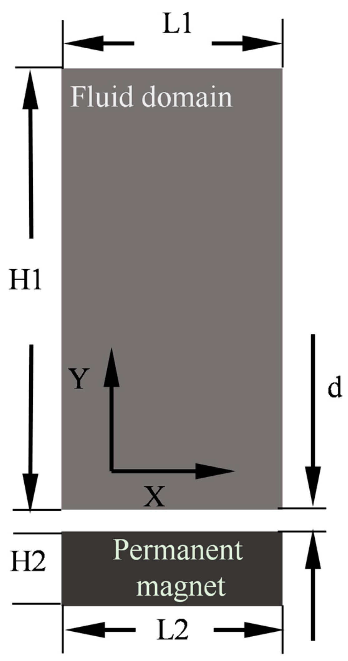
2.1. Geometric Models

In the present work, a cylindrical permanent magnet was chosen as the magnetic field source. In order to analyze the magnetic field force alone, we simulated a static container containing a fluid placed on the top of a permanent magnet, and the fluid velocity was defined as 0 m/s. The geometric model is shown in Figure 1, and the detailed geometric parameters are shown in Table 1. The air domain around the fluid domain should also be accounted for when solving for the ambient magnetic field intensity distribution around the magnetic source.

2.2. Magnetic Field Distribution

The constitutive relationship between magnetic induction and magnetic field strength in all domains is described by Equation (1), and the distribution of magnetic induction can be determined by combining Maxwell’s equations, as following Equation (2).
B = μ 0 μ R A H + B r ,
· B = 0 ,
where μ 0 is the vacuum permeability, μ R A is the relative permeability of air, B is the magnetic induction strength, H is the magnetic field strength, B r is the remanence of the permanent magnet, and the direction of magnetization of the permanent magnet is defined as the Y direction. Here we have chosen three different values of remanence to generate different magnetic field strengths.

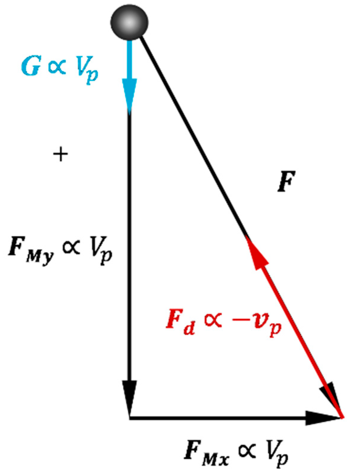
2.3. Mechanical Analysis of Magnetic Particle Motion

The forces on magnetic particles in the fluid under the action of a magnetic field mainly include magnetic field force, fluid traction force, and gravity. When the concentration of particles is low enough in the fluid, the forces between the particles can be ignored for ease of calculation. The mechanical analysis is based on Newton’s second law as follows:
m p a = F ,
F = F d + G + F M ,
where m p is the mass of the particle, a is the acceleration of the particle, F d is the fluid traction, G is the gravitational force, and F M is the magnetic force. According to the Stokes drag force equation,
F d = 3 π η D ( v p v f ) ,
where η is the dynamic viscosity, D is the particle diameter, v p is the particle velocity, and v f is the fluid velocity. In this paper, the movement of magnetic particles in a stationary fluid under the action of a magnetic field is analyzed as an example, i.e., v f is 0. The calculation of the magnetic field force F M can be the focus of the following discussion.

2.4. Magnetic Field Forces and Magnetization Models

In general, the magnetic force on a magnetic particle was calculated by the following Equation (6) [23]
F M = V p μ 0 M H ,
where V p is the volume of the particle, M is the magnetic moment per unit volume of the magnetic particle in the magnetic field, i.e., the magnetization strength, and H is the magnetic field strength.
According to the Equation (6), the magnetic field force on a magnetic particle is not only influenced by the external magnetic field strength H, but the magnetization M of the magnetic particle itself also affects the magnitude of the magnetic field force. Regarding the magnetization model of magnetic particles in a magnetic field, many researchers simply described it using Equation (7) [14,24,25,26]. This equation considered that the magnetization strength of a magnetic particle varies linearly with the external magnetic field strength, and the slope χ is the magnetic susceptibility of the magnetic particle.
M = χ H ,
In fact, the magnetization of the magnetic particles can reach saturation when the external magnetic field is sufficiently strong, i.e., the magnetization strength will no longer vary linearly with the magnetic field strength; at that time, Equation (7) is no longer applicable either. To take into account the effect of the magnetic saturation phenomenon, we proposed a magnetization model based on the actual magnetic characteristic curves of magnetic particles. Taking a common superparamagnetic Fe3O4 nanoparticle as an example, its diameter is about 300 nm. The magnetic hysteresis loop was measured by a magnetic property measurement system (VSM, 7404, LakeShore, Columbus, OH, USA), as shown in Figure 2. The Fe3O4 nanoparticles exhibited typical superparamagnetism, and the remanence was almost zero. The magnetization process of magnetic particles can be described in two stages: the first stage was defined as the initial magnetization stage, and the second stage was defined as the magnetization saturation stage. In the initial magnetization stage, the magnetization intensity of the magnetic particle was approximately linear with increasing external magnetic field strength. In the magnetization saturation stage, the magnetization intensity of the magnetic particle no longer changed with increasing external magnetic field strength. Here, two straight lines were plotted tangent to the magnetization curves of the two stages, as shown in Figure 2, and the coordinates of the intersection of the tangent lines were defined as ( H 0 , M 0 ). When |H| < H 0 , magnetization belonged to the initial magnetization stage I; the relationship between the magnetization intensity and the magnetic field strength could be described by Equation (7). For |H| > H 0 , the magnetization process was considered to have reached the magnetic saturation stage II, and the magnetic saturation intensity was M 0 . Considering the two magnetization stages, the relationship between the M and H can be described by Equation (8). According to the result shown in Figure 2, H 0 = 58.26 kA/m, M 0 = 450.64 kA/m, and the magnetic susceptibility χ was equal to 7.74. These values will be used for further discussion and analysis in the following section.
M = { χ H ,     | H | < H 0 M s H | H | ,     | H | H 0 ,
Then, the magnetic field force equation becomes
F M = { V p μ 0 χ ( H H ) ,     | H | < H 0 V p μ 0 M s | H | ( H H ) ,     | H | H 0 ,
The magnetic volume force vector in a two-dimensional coordinate system can be described by the following Equations (10) and (11)
f M x = { μ 0 χ ( H x H x x + H y H x y ) ,     | H | < H 0 μ 0 M s | H | ( H x H x x + H y H x y ) ,     | H | H 0 ,
f M y = { μ 0 χ ( H x H y x + H y H y y ) ,     | H | < H 0 μ 0 M s | H | ( H x H y x + H y H y y ) ,     | H | H 0 ,
The model was solved using the AC/DC and particle tracking modules of the COMSOL multi-physics field analysis software. The physical parameters required for the simulation are shown in Table 2. The magnetic field forces along the X and Y directions were defined as a variable that varied with the magnetic field strength and were calculated, respectively. The kinetic analysis was carried out in each direction, with the magnetic particles as the object of study, to obtain the trajectory of the particles.

3. Simulation Results

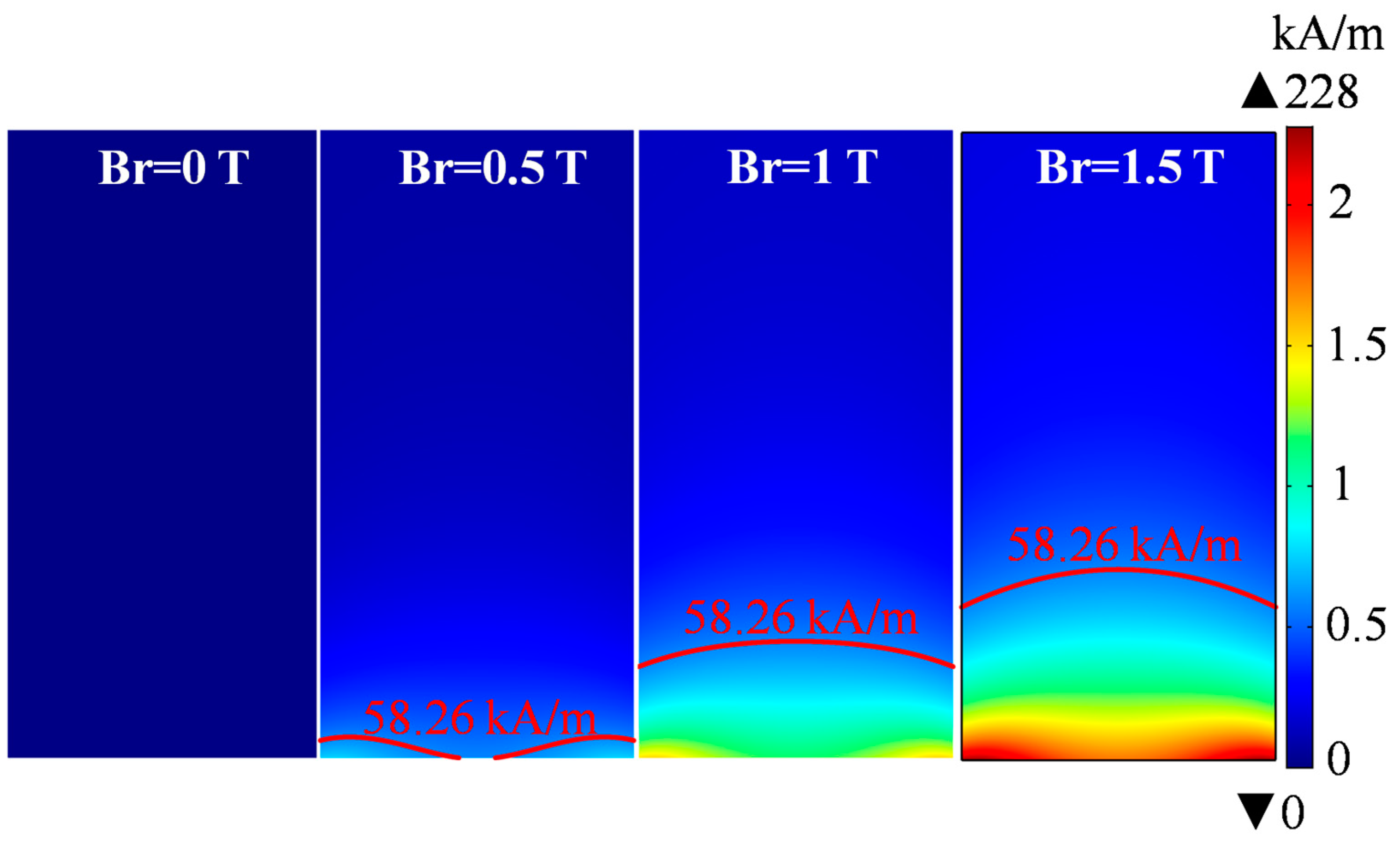
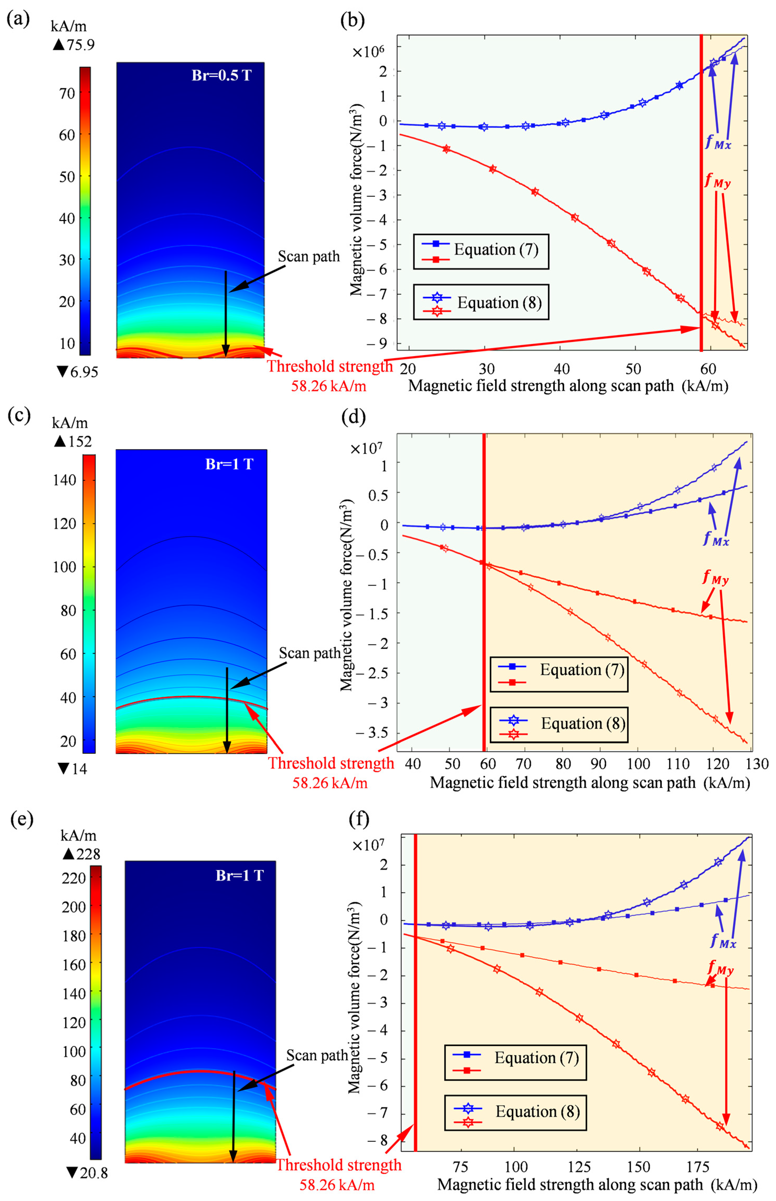
3.1. Magnetic Field Strength and Magnetic Volume Force Distribution

Figure 3 shows the distribution of magnetic field strength in the fluid domain when the permanent magnets have different remanences, 0, 0.5, 1, and 1.5 T, respectively. The critical magnetic field strength calculated from the above is 58.26 kA/m, and the corresponding isoline is shown in the red curve in Figure 3. The fluid domain could be then divided into two regions by the isoline, i.e., the non-magnetic saturation region above the isoline and the magnetic saturation region below the isoline. Obviously, the greater the remanence, the greater the magnetic saturation zone, which also indicates that it is necessary to consider the existence of a magnetic saturation phenomenon when the magnetic field is strong enough.
To compare the magnetic forces calculated using a different magnetization model, Figure 4 shows the distribution of the magnetic volume force distribution in the fluid domain. Here, I represents the conventional magnetization model, i.e., Equation (7), and II represents the magnetization model proposed in this paper, i.e., Equation (8). The black boundary line in the figure was the isoline of the magnetic field strength, with 58.26 kA/m. It can be seen that there is a clear difference in the magnitude of the magnetic volume force calculated using the two magnetization models in the region below the black critical isoline. In order to quantify the difference, a vertical path was selected, as shown by the black vertical line in Figure 5, and the magnetic volume forces calculated using the two magnetization models were compared along this path. The calculated results are shown in Figure 5b,d,f, corresponding to Br = 0.5, 1, and 1.5 T, respectively. It was found that the magnetic volume forces calculated by the two models were the same in the unsaturated region, while the deviation occurred when magnetic field strength was higher than the critical strength. Obviously, the higher the Br value, the earlier and larger the deviation was, as shown in Figure 5b,d,f. When the magnetic field strength reached 175 kA/m, the magnetic forces calculated by the two models were up to four times different in value. It can be seen that when the magnetic field strength did not reach the magnetic saturation value of the magnetic particles, the traditional model was still applicable. However, when the magnetic field strength exceeded the critical strength H0, it was necessary to consider the influence of the magnetic saturation of the magnetic particles in order to accurately calculate the magnetic volume force.

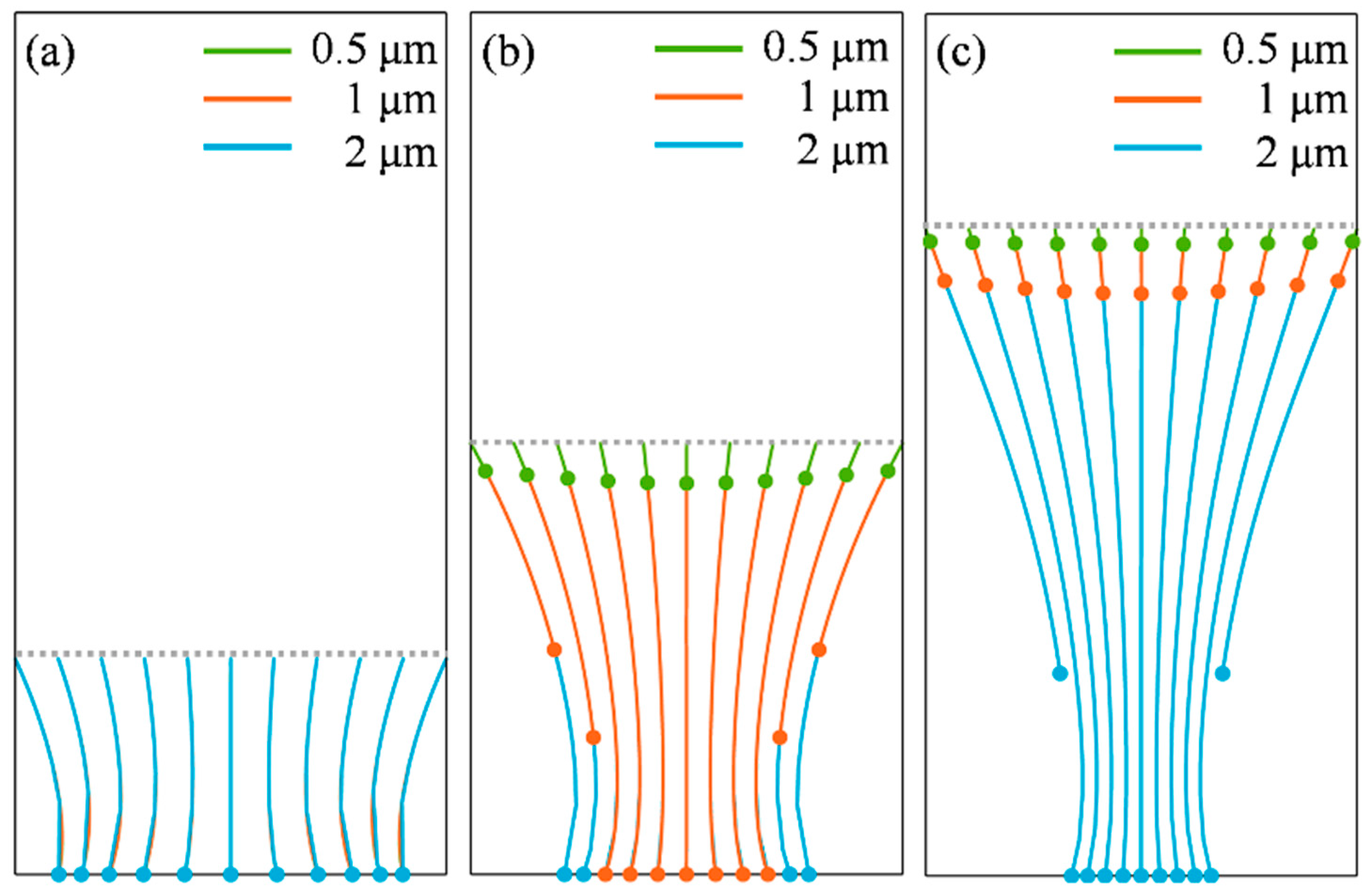
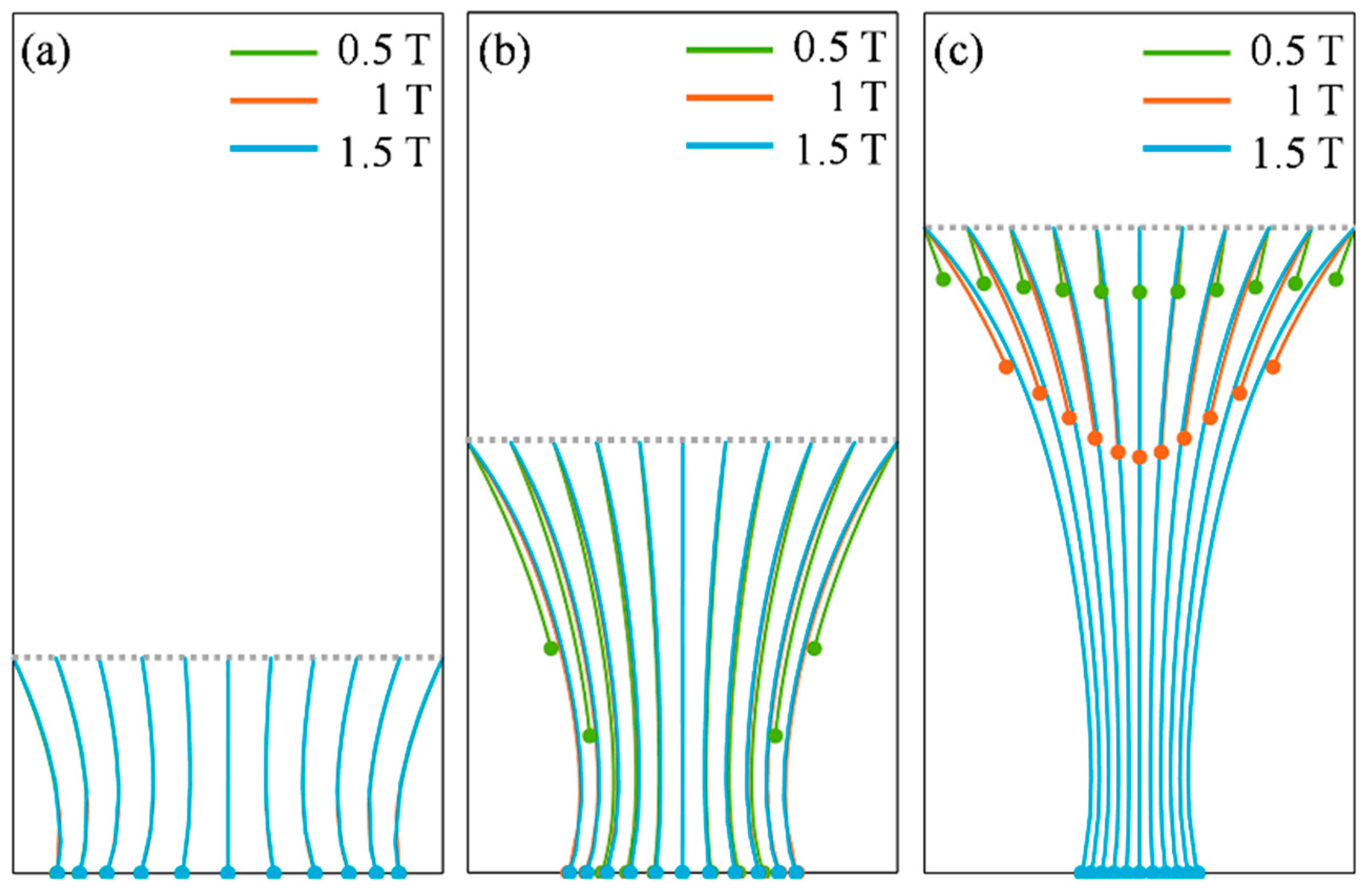
3.2. Trajectories of Magnetic Particles with Different Diameters

The trajectories of magnetic particles with three kinds of diameter (0.5 μm, 1 μm, and 2 μm) under the influence of a magnetic field were simulated. To investigate the trapping of particles with different locations in fluid by the magnetic field source, three releasing positions were defined in the fluid domain, with heights of 5 mm, 10 mm, and 15 mm from the bottom of the fluid domain, respectively. Ten particles with different diameters were released simultaneously. Figure 6 shows the trajectory of magnetic particles with different particle sizes under the magnetic field generated by the magnet with a remanence of 0.5 T over a period of 300 s. It was found that the particles with different particle diameters followed the same path downwards, regardless of the releasing position, and the larger particles moved further away within the same time. For a release height of 5 mm, the final position of the particles was the same for all three particle sizes, which meant that all three particle sizes reached the bottom of the fluid domain within 300 s.

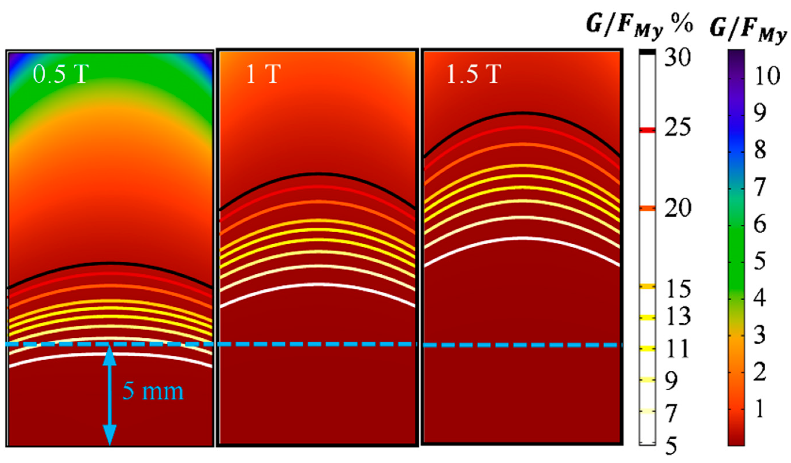
3.3. The Effect of the Remanence on the Trajectory of Particles
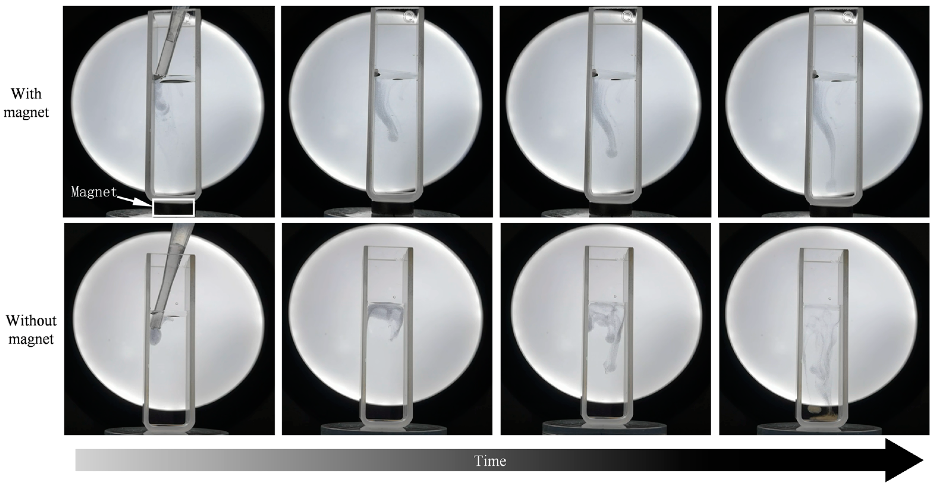
Figure 7 shows the trajectories of magnetic particles with diameter of 1 μm under the action of the magnet with different remanences, taking a moving time of 300 s. It was found that the trajectory of the particles did not change with the increasing remanence when the releasing height was 5 mm. However, when the releasing heights were 10 mm and 15 mm, as shown in Figure 7b,c, the changes in remanence caused an obvious difference in the trajectory of the particles. The higher the particle releasing position, the greater the deviation in the trajectory of the particles caused by the change in remanence.
As can be seen from the above simulation results, the particle diameter and remanence of the magnet exhibited different effects on the movement of the particles, and different releasing heights also seemed to change the trajectory of the particles. The relevant mechanism will be further analyzed in the following discussion section.

4. Discussion

A force analysis of a single magnetic particle in a fluid was carried out to understand the effect of particle diameter and remanence of a magnet on the trajectory of the magnetic particles, as shown in Figure 8. It can be found that the motion of the particle along the X direction is mainly determined by the magnetic field force F M x , while the motion along the Y direction is determined by both gravity and the magnetic field force F M y . Since both the magnetic field force and gravity are bulk forces, magnetic particles with different diameters move along the same trajectory, and the speeds of different diameter particles are different due to FM and G and are proportional to volume. The larger the particle size, the greater the gravitational and magnetic forces, and the faster the motion.
However, the strength of the magnetic field in the fluid domain changed as the remanence varied, which in turn changed the magnitude of F M x and F M y . As the gravity in the Y direction was constant, the forces on the particles along the X and Y directions no longer changed proportionally. This could be the main reason as to why the trajectory of the particles changed when a different remanence was adopted, as shown in Figure 7. However, it is worth noting that, as shown in Figure 7, when the releasing height was 5 mm, the trajectory of the particles was same for all remanences. Based on this phenomena, we further focused on the ratio of the Y-directional force, the gravity G to F M y , as shown in Figure 9. It was clear that the closer to the bottom of the fluid domain, the smaller the value of G/ F M y . It can be seen that the ratio of the G/ F M y was only about 5% for three different remanences at 5 mm from the bottom. Combining the trajectory of the particles shown in Figure 7a, when the proportion of gravity in the Y-directional force on the particle was so small, about 5%, that it could be ignored, the motion direction of particles was mainly determined by the magnetic field force. Because F M x and F M y varied proportionally as the remanences changed, this may be the reason as to why the trajectory of particles remained the same when different remanences were applied at a releasing height of 5 mm.
Considering the limited experimental conditions, it is difficult to observe the motion of individual nanoparticles under a magnetic field. So, we designed a simple experiment to observe the motion of magnetic particles in a liquid-phase fluid under a magnetic field. The experimental details were as follows. A transparent cuvette containing aqueous solution was placed on a cylindrical permanent magnet with a remanence of approximately 1.2 T. The mixture containing the magnetic particles was then injected into the aqueous solution using a pipette, and the trajectory of the magnetic particles was recorded in real time using a high definition camera. The trajectory of the particles in the absence of a magnet was also observed as a comparison. The observed images are shown in Figure 10. Magnetic particles disorderly fell under gravity in the absence of a magnetic field. In the presence of a magnetic field, the magnetic particles showed a lateral shift toward the center of the cuvette as they fell; this trend is similar to the simulated results in Figure 6 and Figure 7.

5. Conclusions

In the present work, we proposed a new model to describe the magnetization process of superparamagnetic particles in a magnetic field based on the real magnetic property curve of magnetic particles for accurately calculating the magnetic force on the superparamagnetic particle. With the aid of finite element analysis software, the trajectories of magnetic particles of different particle sizes were visualized and analyzed, also considering the influence of the magnet’s remanence. The simulation results show that under the action of a magnetic field, changing the particle size only affects the velocity of the particle, but not the trajectory of the particle; considering the action of gravity, changing the magnitude of magnetic field strength will change the trajectory of the particle. However, when the ratio of gravity to magnetic field force in the Y direction is less than 5%, the effect of gravity may be ignored; additionally, changing the magnitude of magnetic field strength does not affect the trajectory of the particles and only affects the moving speed of the particles. This work provides a method to accurately analyze the trajectory of magnetic particles in fluids, and provides a theoretical underpinning for the fields that require a precise control of magnetic particle motion, such as drug-targeted medicine, mechanical target lubrication, etc.

Author Contributions

Conceptualization, Q.Z. and X.H.; methodology, Q.Z. and H.S.; software, Q.Z.; validation, Q.Z., H.S. and R.S.; formal analysis, Q.Z.; investigation, Q.Z. and X.H.; resources, X.H.; data curation, Q.Z. and X.H.; writing—original draft preparation, Q.Z.; writing—review and editing, X.H.; visualization, Q.Z.; supervision, R.S. and X.H.; project administration, X.H.; funding acquisition, X.H. All authors have read and agreed to the published version of the manuscript.

Funding

This research was supported by the National Natural Science Foundation of China (Grant No. 52075141).

Institutional Review Board Statement

Not applicable.

Informed Consent Statement

Not applicable.

Data Availability Statement

Data supporting our results are available from the corresponding author of this article.

Conflicts of Interest

The authors declare no conflict of interest.

References

  1. Zhang, J.; Misra, R.D. Magnetic drug-targeting carrier encapsulated with thermosensitive smart polymer: Core-shell nanoparticle carrier and drug release response. Acta Biomater. 2007, 3, 838–885. [Google Scholar] [CrossRef]
  2. Honaker, R.; Saracoglu, M.; Huang, Q. Evaluation of a novel coal flotation improvement approach with the addition of hydrophobic magnetic particles. Int. J. Coal Prep. Util. 2020, 40, 843–859. [Google Scholar] [CrossRef]
  3. Amyn, S.; Teja, P. Synthesis, properties, and applications of magnetic iron oxide nanoparticles. Prog. Cryst. Growth Chract. Mater. 2009, 55, 22–45. [Google Scholar]
  4. Wang, J.; Tang, B.; Tsuzuki, T.; Liu, Q.; Hou, X.; Lu, S. Synthesis, characterization and adsorption properties of superparamagnetic polystyrene/Fe3O4/graphene oxide. Chem. Eng. J. 2012, 204–206, 258–263. [Google Scholar] [CrossRef]
  5. Toghraie, D.; Alempour, S.; Afrand, M. Experimental determination of viscosity of water based magnetite nanofluid for application in heating and cooling systems. J. Magn. Magn. Mater. 2016, 417, 243–248. [Google Scholar] [CrossRef]
  6. Borbáth, T.; Bica, D.; Potencz, I.; Vékás, L.; Borbáth, I.; Boros, T. Magnetic nanofluids and magnetic composite fluids in rotating seal systems. IOP Conf. Ser. Earth Environ. Sci. 2010, 12, 012105. [Google Scholar] [CrossRef]
  7. Kim, Y.; Kim, Y. Application of ferro-cobalt magnetic fluid for oil sealing. J. Magn. Magn. Mater. 2003, 267, 105–110. [Google Scholar] [CrossRef]
  8. Wang, H.; Yan, L.; Liu, D.; Wang, C.; Zhu, Y.; Zhu, J. Investigation of the tribological properties: Core-shell structured magnetic Ni@NiO nanoparticles reinforced epoxy nanocomposites. Tribol. Int. 2015, 83, 139–145. [Google Scholar] [CrossRef]
  9. Zhou, G.; Zhu, Y.; Wang, X.; Xia, M.; Zhang, Y.; Ding, H. Sliding tribological properties of 0.45% carbon steel lubricated with Fe3O4 magnetic nano-particle additives in baseoil. Wear 2013, 301, 753–757. [Google Scholar] [CrossRef]
  10. Zhang, Q.; Wu, B.; Song, R.; Song, H.; Zhang, J.; Hu, X. Preparation, characterization and tribological properties of polyalphaolefin with magnetic reduced graphene oxide/Fe3O4. Tribol. Int. 2020, 141, 105952. [Google Scholar] [CrossRef]
  11. Kianfar, E. Magnetic Nanoparticles in Targeted Drug Delivery: A Review. J. Supercond. Nov. Magn. 2021, 34, 1709–1735. [Google Scholar] [CrossRef]
  12. Alrushaid, N.; Khan, F.A.; Al-Suhaimi, E.A.; Elaissari, A. Nanotechnology in cancer diagnosis and treatment. Pharmaceutics 2023, 15, 1025. [Google Scholar] [CrossRef]
  13. Zhang, Q.; Song, H.; Wu, B.; Feng, W.; Li, X.; Jiao, Y.; Hu, X. Effect of magnetic field on the tribological behaviors of Fe3O4@MoS2 as polyalphaolefin additive in the steel/steel friction interface. Wear 2021, 466–467, 203586. [Google Scholar] [CrossRef]
  14. Xue, Z.; Wang, Y.; Zheng, X.; Lu, D.; Li, X. Particle capture of special cross-section matrices in axial high gradient magnetic separation: A 3D simulation. Sep. Purif. Technol. 2020, 237, 116375. [Google Scholar] [CrossRef]
  15. Krafcik, A.; Babinec, P.; Strbak, O.; Frollo, I. A theoretical analysis of magnetic particle alignment in external magnetic fields affected by viscosity and brownian motion. Appl. Sci. 2021, 11, 9651. [Google Scholar] [CrossRef]
  16. Furlani, E.; Ng, K. Nanoscale magnetic biotransport with application to magnetofection. Phys. Rev. E 2008, 77, 061914. [Google Scholar] [CrossRef]
  17. Sinha, A.; Ganguly, R.; Puri, I. Magnetic separation from superparamagnetic particle suspensions. J. Magn. Magn. Mater. 2009, 321, 2251–2256. [Google Scholar] [CrossRef]
  18. Haverkort, J.; Kenjeres, S.; Kleijn, C. Computational simulations of magnetic particle capture in arterial flows. Ann. Biomed. Eng. 2009, 37, 2436–2448. [Google Scholar] [CrossRef]
  19. Shi, Z.; Chen, S.; Sun, J.; Li, M.; Jia, S. Three-dimensional numerical analysis of focusing and separation of diamagnetic particles in ferrofluid. J. Phys. D Appl. Phys. 2020, 53, 315002. [Google Scholar] [CrossRef]
  20. Takayasu, M.; Gerber, R.; Friedlaender, F. Magnetic separation of submicron particles. IEEE Trans. Magn. 1983, 19, 2112–2114. [Google Scholar] [CrossRef]
  21. Furlani, E.; Xue, X. Field, force and transport analysis for magnetic particle-based gene delivery. Microfluids Nanofluids 2012, 13, 589–602. [Google Scholar] [CrossRef]
  22. Sun, J.; Shi, Z.; Chen, S.; Jia, S. Experimental and numerical analysis of the magnetophoresis of magnetic nanoparticles under the influence of cylindrical permanent magnet. J. Magn. Magn. Mater. 2019, 475, 703–714. [Google Scholar] [CrossRef]
  23. Karpov, A.; Kozireva, S.; Avotina, D.; Chernobayeva, L.; Baryshev, M. Investigation of nanoparticle distribution formed by the rotation of the magnetic system. J. Magn. Magn Mater. 2014, 369, 86–91. [Google Scholar] [CrossRef]
  24. Zheng, X.; Wang, Y.; Lu, D. Study on capture radius and efficiency of fine weakly magnetic minerals in high gradient magnetic field. Miner. Eng. 2015, 74, 79–85. [Google Scholar] [CrossRef]
  25. Li, X.; Yao, K.; Liu, H.; Liu, Z. The investigation of capture behaviors of different shape magnetic sources in the high-gradient magnetic field. J. Magn. Magn. Mater. 2007, 311, 481–488. [Google Scholar] [CrossRef]
  26. Tokura, S.; Hara, M.; Kawaguchi, N.; Amemiya, N. Contactless magnetic manipulation of magnetic particles in a fluid. J. Magn. Magn. Mater. 2016, 411, 68–78. [Google Scholar] [CrossRef]
Figure 1. Schematic diagram of the two-dimensional geometric model.
Applsci 13 05406 g001
Figure 2. Magnetic hysteresis loop of magnetic particles obtained from a magnetic property measurement system.
Applsci 13 05406 g002
Figure 3. Magnetic field strength distribution in the fluid domain for different remanences.
Applsci 13 05406 g003
Figure 4. Magnetic volume force distribution in the fluid domain for different remanent magnetic strengths. I represents the magnetic force calculated according to the conventional magnetization model, i.e., Equation (7); II represents new magnetization model, i.e., Equation (8).
Applsci 13 05406 g004
Figure 5. Quantitative comparison of the magnetic volume forces calculated by different magnetization models under the action of different remanences. (a,b) Br = 0.5 T; (c,d) Br = 1 T; (e,f) Br = 1.5 T.
Applsci 13 05406 g005
Figure 6. Trajectories of magnetic particles with different diameters released at different releasing positions. (a) Releasing position 5 mm from the bottom; (b) releasing position 10 mm from the bottom; (c) releasing position 15 mm from the bottom. The remanence of the magnet is 0.5 T.
Applsci 13 05406 g006
Figure 7. The effect of remanence on the trajectory of particles at different releasing positions. (a) Releasing position 5 mm from the bottom; (b) releasing position 10 mm from the bottom; (c) releasing position 15 mm from the bottom. The diameter of particle is 1 μm.
Applsci 13 05406 g007
Figure 8. Force analysis of magnetic particles in fluid domain.
Applsci 13 05406 g008
Figure 9. The distribution of the value of G/ F M y in the fluid domain under the action of different remanences.
Applsci 13 05406 g009
Figure 10. Observed images of the trajectory of a magnetic particle under the action of a magnetic field.
Applsci 13 05406 g010
Table 1. Geometric model size parameters.
SymbolsL1H1L2H2d
Values (mm)10201031.25
Table 2. The physical parameters required for the simulation.
Vacuum PermeabilityRelative Permeability of AirRemanenceFluid DensityFluid Dynamic ViscosityParticle Density
× 10−7 H/m10.5 T, 1 T, 1.5 T1000 kg/m38.94 × 10−4 Pa · s 5180 kg/m3
Disclaimer/Publisher’s Note: The statements, opinions and data contained in all publications are solely those of the individual author(s) and contributor(s) and not of MDPI and/or the editor(s). MDPI and/or the editor(s) disclaim responsibility for any injury to people or property resulting from any ideas, methods, instructions or products referred to in the content.

