Article

Study on the Dynamic Generation of Subcooled Water Using a Compact Heat Exchanger

1
College of Engineering, Zhejiang Normal University, Jinhua 321004, China
2
Zhejiang Xuebolan Technology Co., Ltd., Jinhua 321100, China
*
Author to whom correspondence should be addressed.
Appl. Sci. 2023, 13(7), 4369; https://doi.org/10.3390/app13074369
Submission received: 14 February 2023 / Revised: 21 March 2023 / Accepted: 28 March 2023 / Published: 29 March 2023

Abstract

:
The dynamic generation of ice slurry from subcooled water is one of the most promising ways to make ice; this process is utilized widely in ice storage air-conditioning systems. However, the random occurrence of ice blockage during the generation of subcooled water using conventional heat exchangers prevents the increase in subcooling, thereby reducing the efficiency of the release of the subcooled water and converting it into ice slurry. A more efficient approach to reducing the fluid passage time is to employ a compact heat exchanger with a highly efficient heat transfer performance, a heat transfer length of only 21.5 mm, and a hydraulic diameter of 0.32 mm. A compact heat exchanger was used to build a dynamic generation setup for subcooled water, and 40 wt% of non-freezing liquid and tap water was used as the working fluid for heat exchange to generate subcooled water. The results show that the compact heat exchanger can achieve a greater subcooling degree (3.8 K) and longer duration (108 min). This study further explored the potential for dynamic ice making from deep, subcooled water and improved the overall structure of the compact heat exchanger used. The experimental setup is recommended based on the analysis of the results.

1. Introduction

In a state where the saturation pressure corresponds to the saturation temperature, the temperature of water will be below the freezing temperature and still in the liquid phase, thus being called subcooled water [1]. Ice or ice slurry form after the subcooled water is released, possessing the characteristics of a high latent heat and quick release of the cold temperature. In ice storage air conditioning, food preservation, and medical fields, this process is widely utilized [2,3]. The ice slurry formed by subcooled water, also known as pumpable ice or binary ice, is a kind of ice–water mixture that is easy to transport, has a large contact area, and can cool substances evenly and quickly.
Heat exchangers play a crucial role in the dynamic generation of subcooled water systems [4,5] which, currently, are mainly modified double-tube heat exchangers or plate heat exchangers used to dynamically generate subcooled water for ice storage. However, ice blockage can occur randomly and disrupt the generation of subcooled water [6,7]. When ice blockage occurs, the process must be stopped and can only restart after the ice melts. This disruption through stopping and restarting again leads to an increased amount of energy consumed. Between 0 and 2 °C, subcooled water is commonly used in dynamic ice storage systems to for cold storage, and the ice storage tank has an ice packing factor (IPF) in the range of only 30~40% [8,9], and this results in space wastage. Only a minor fraction of the subcooled water is converted into ice after the release through subcooling because of the small subcooling degree [1,10]. This process requires constant water circulation in the ice storage tank for recooling to increase the ice storage capacity [3,11]. Since the thermal resistance of a double-tube or plate heat exchanger is high, it is imperative to keep the inlet water temperature at 0~0.5 °C in order to keep the cooling source temperature at a high level for energy saving purposes [7,12]. However, this inlet water temperature requires the installation of a front heater to eliminate the ice crystals that may be contained in the water, complicating the system setup and control. A greater subcooling degree of subcooled water leads to the release of more energy. A more powerful subcooling process allows for easier the generation of ice or ice slurry, which saves time in ice making and can expand its range of applications, such as indoor snowmaking, seafood preservation, and more.
The causes of ice blockage are complex and are mainly related to the heat exchanger and the aqueous solution used for ice making. The materials of heat exchangers determine the minimum temperature of the subcooled water. Stainless steel and copper are the most common metallic materials in subcooling heat exchangers [11,13]. The channel lengths and hydraulic diameters of the heat exchangers that are currently used are generally above 2000 mm and 5 mm, respectively, while the inner wall surface of the heat exchanger should also possess a high degree of finishing work to achieve the dynamic generation of subcooled water [7,11]. For example, the authors of [6] achieved a minimum temperature of −3.3 °C of subcooled water at a specific time using a specialized double-tube heat exchanger that was 3000 mm long with a hydraulic diameter of 8 mm, using pure water as the working fluid. Still, it was necessary to keep the cold source at approximately −15 °C. The authors of [14] achieved −2.1 °C subcooled water with a double-tube heat exchanger of 3800 mm in length and 10.5 mm in hydraulic diameter using non-freezing liquid (NFL) and water (test water) as the working fluid. The authors of [10] used a plate heat exchanger to achieve the dynamic generation of subcooled water at −1.4 °C. The medium used to generate subcooled water is usually water of a high purity or an aqueous solution with nucleation inhibitors to reduce the risk of ice blockage during the generation of subcooled water [7,15]. Such working media are not only cost-prohibitive but can also be contaminated, which is unfavorable for engineering and food applications. The dynamic generation of subcooled water with a high subcooling degree is hampered by the sole improvement of conventional heat exchangers alone; therefore, new approaches are necessary to explore how we can generate lower-temperature subcooled water for a longer duration. One method uses a compact heat exchanger [16,17] with a significantly shorter channel length than conventional heat exchangers. However, a different approach was adopted to reduce the risk of ice blockage arising from uncertainties by taking advantage of the high heat transfer coefficient of the compact heat exchanger. This method can significantly reduce the heat transfer length and the time required for the subcooled water to pass through the heat exchanger.
The compact heat exchanger used in this study has a hydraulic diameter of 0.32 mm, a channel length of 21.5 mm, and a channel number of 720. The compact heat exchanger has a cross-sectional area of 16.4 mm2, and its shape is rectangular. When water passes through the channels at a flow rate of 0.017–0.032 L/s, it stays in the heat exchanger for 0.038–0.072 s. The objective of this study is to investigate which low-temperature conditions are required to increase the subcooling degree of water for a longer duration. Under certain conditions of this passage time range and inlet temperature of the heat exchanger, we aimed to provide design guidelines for the subsequent development of a high-performance compact heat exchanger that dynamically generates subcooled water.

2. Experimental Setup and Experimental Conditions

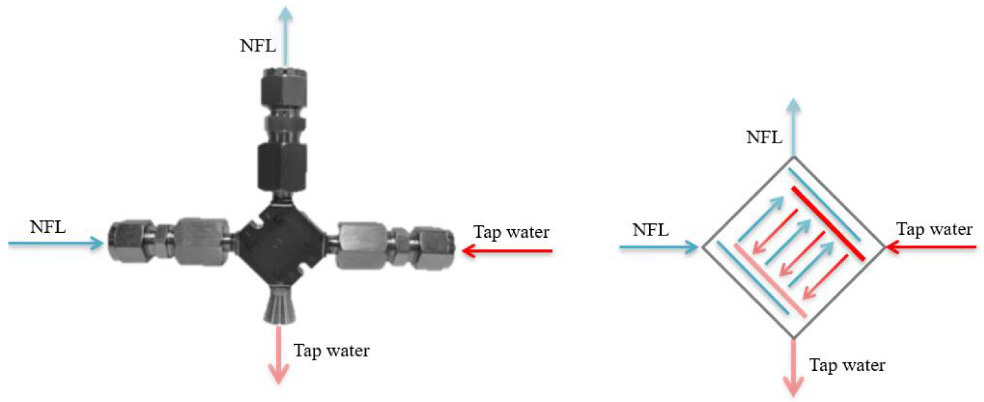
2.1. Selection of Compact Heat Exchanger

When considering compact heat exchangers, the concept of high-performance heat exchangers, which refers to a heat transfer area of 500–700 per unit volume (m2/m3) and a hydraulic diameter of less than 5 mm, is relevant [17]. In this paper, the compact heat exchanger used for the dynamic generation of subcooled water had a heat transfer area of 2990 per unit volume (m2/m3) and a hydraulic diameter of 0.32 mm, being a heat exchanger with an excellent performance and high compactness [16]. The details are in Table 1. The compact heat exchanger was designed based on thermal resistance balance combined with a microstructural approach [16]. The heat exchanger contains multiple fluid channels, each separated by one layer of the same fluid channel, where the working fluid enters the center from its respective inlet, and the multi-layered channels are divided on this side and converge at the outlet for outflow. The compact heat exchanger has a counter-flow heat transfer structure, in which low-temperature non-freezing liquid (NFL, 40 wt% aqueous solution of ethylene glycol) and tap water flow into the heat exchanger on both sides of the channel through convective heat transfer to dynamically generate subcooled water. This process is shown in Figure 1. The flow of low-temperature non-freezing liquid is higher than the flow of tap water so as to enhance the turbulence strength and save energy.
Water below the freezing point without freezing is called subcooled water, which exists in a metastable state and can reach −38 °C in homogeneous nucleation while still in the liquid phase [18]. The ice nucleation process forms ice and then undergoes ice growth. For water below zero degrees Celsius, the solid phase (ice) is thermodynamically more stable than the liquid phase, because the free energy of the solid phase per molecule is lower than that of the liquid phase. However, when a small ice embryo forms and grows in the liquid phase, the total free energy of the system increases as the ice embryo grows, owing to the increase in interfacial free energy. As a result, the water can be cooled below zero degrees Celsius and exist in a subcooled state without ice nuclei.
Conversely, suppose that the ice embryo size exceeds the critical value, which depends on the degree of subcooling; the total free energy decreases as the ice embryo grows, and thus the ice nucleation process takes place. In liquid water, homogenous nucleation is extremely rare; in most cases, ice nucleation occurs on solid surfaces. To some extent, the presence of solid surfaces reduces the amount of interfacial free energy [19]. In this study, ice was formed by heterogeneous nucleation, considering the fact that certain factors, such as impurities in the water, small energy perturbations, and the cooling time, can play a catalytic role in ice nucleation.
Inaba studied the influences of various factors on the dynamic generation of subcooled water [20]. After considering the relationship between the parameters of the subcooled pipe and the hydrothermal conditions, the dimensionless degree of subcooling θ f and the Graetz number G z * was introduced to judge whether, theoretically, the subcooled water could be dynamically generated:
θ f = ( T f T w 1 ) / ( T b 1 T w 1 )
G z * = ( l s / d i ) / ( R e P r )
where T f represents the freezing temperature of the water and T w 1 symbolizes the inner surface temperature of the subcooled tube. T b 1 is the temperature of the water at the subcooled water outlet, and the d i is the hydraulic diameter of the subcooled channel. The length l s is the distance from the position where the average temperature of the test fluid reaches the freezing temperature to the cooling tube exit. R e and P r are the Reynolds number and Prandtl number, respectively.
When subcooled water is generated dynamically in laminar flow conditions,
θ f = 33.10 G z * + 1
When subcooled water is generated dynamically in turbulent flow conditions,
θ f = 6.18 ( G z * / ( C f R e N u ) ) 0.37 + 1
where C f and N u l are the friction coefficient and Nusselt number, respectively.
The relationship between θ f and G z * shows that G z * directly affects the size of θ f , and l s and d i determine the value of G z * . Therefore, an increase in θ f can be achieved by increasing l s or decreasing d i . Comparing Equations (3) and (4) shows that laminar flow conditions are more likely to generate subcooled water, while turbulent flow conditions can increase the heat transfer intensity, but the wall friction C f , Reynolds number R e , and Nusselt number N u all cause θ f to decrease. Therefore, retaining minor disturbances during laminar flow is more beneficial for improving the heat transfer efficiency. Considering the effect of uncertainties on the duration time, such as the fact the longer the length of the heat transfer channel is, the longer the water will stay in the heat exchanger, and the greater its chance of being affected by uncertainties, such as impurities, will be, it is preferable to reduce d i while proportionally reducing l s .
The design of the compact heat exchanger for the dynamic generation of subcooled water includes a very small hydraulic diameter ( d i ) and multi-pass structures, as well as short channels, with a much higher average convective heat transfer coefficient than that of conventional heat exchangers. The heat transfer channels’ length can ensure that heat transfer requirements are met, even when they are shorter (less than 25 mm).

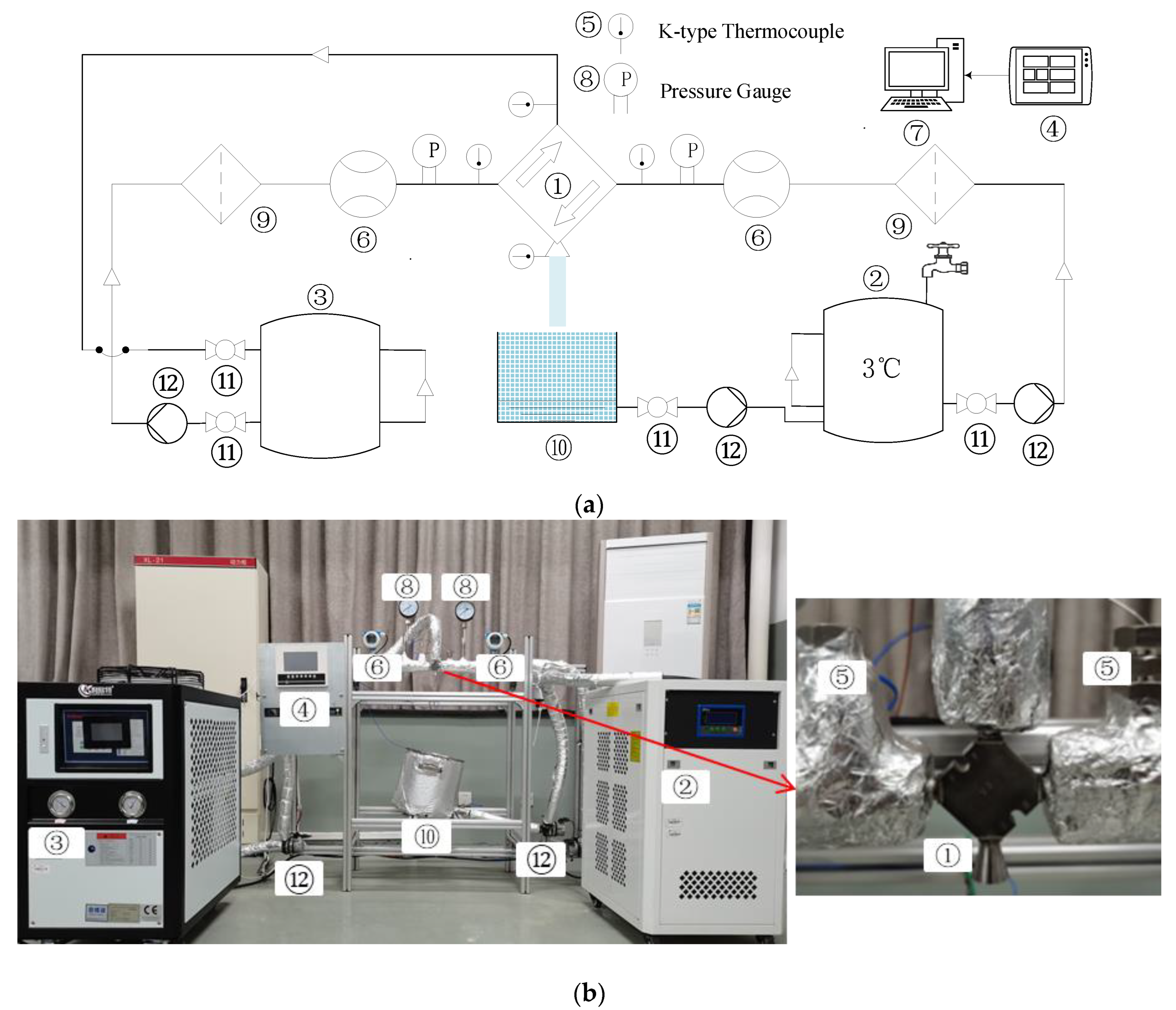
2.2. Experimental Setup

The setup for the dynamic generation of subcooled water mainly consists of a low-temperature NFL loop (left) and a loop for the dynamic generation of subcooled water (right), which are connected by a compact heat exchanger ①, as shown in Figure 2. The components in front of the heat exchanger inlet in both loops are identical and arranged symmetrically. The low-temperature NFL loop provides the cooling capacity as a closed loop and is driven and controlled by a variable frequency pump ⑫. Then, through a pre-filter (40 μm), the NFL is filtered before entering the heat exchanger to prevent blockage due to impurities. Next, it passes through a turbine flow meter ⑥, a pressure gauge ⑧, and a K-type thermocouple ⑤ into the compact heat exchanger, where the pressure gauge mainly monitors the loop pressure status and is not used as a parameter for collection. After heat exchange with the tap water, the NFL flows back into the low-temperature thermostatic device ③ with a capacity of 33 L, determined through temperature measurement by the K-type thermocouple at the outlet. A semi-open loop, driven by two variable frequency pumps, is used for the subcooled water’s dynamic generation. From the high-temperature thermostatic device ② to the compact heat exchanger inlet, the tap water passes through the same components as the low-temperature non-freezing liquid. After heat exchange with the non-freezing liquid, the temperature of the generated subcooled water is measured at the outlet and then flows into the ice storage tank ⑩ for release through subcooling to form ice or ice slurry. Finally, a variable frequency pump is used to pump away excess water from the storage tank, and the water is then injected into a high-temperature thermostatic device with a capacity of 25 L to reduce the thermostatic load. However, some subcooled water is left in the ice storage tank out of necessity. The subcooled water generation setup also includes a ball valve ⑪ and the insulation material of the pipeline.
The experiments were conducted using a turbine flowmeter and K-type thermocouple to collect the flow magnitude and the inlet and outlet temperature of the heat exchanger on the two loop sides, respectively. The data recorder, which could communicate with the computer through the RS485 module, then collected the parameters, which were output as an Excel file to facilitate the analysis of the experimental results. The turbine flow meters had a flow range of 0.600~4.100 L/min with an uncertainty of ±1.0%, and the K-type thermocouples had a temperature range of −50~50 °C with an uncertainty of ±1 K.

2.3. Experimental Method

In this experiment, for the dynamic generation of subcooled water, a compact heat exchanger was taken as the research object, and tap water and NFL were the working fluids for the dynamic generation of subcooled water. Additionally, the conditions and control methods for the dynamic generation of subcooled water at high subcooling degrees were closely investigated and monitored. During the experiments, the viscosity of the non-freezing fluid increased significantly with the decrease om the working fluid temperature (viscosity from 2.57 mPa·s at 25 °C to 11.74 mPa·s at −15 °C); therefore, the setting of the flow conditions of the NFL was greatly affected by the change in the viscosity of the NFL. At room temperature, the maximum flow rate of the NFL in a compact heat exchanger can reach approximately 2.700 L/min, while at low temperatures (<−6.0 °C), the maximum operating flow rate does not exceed 1.900 L/min. Similarly, the viscosity increases the subcooling of the tap water. However, it has less influence on the flow rate q2 of the tap water operation, which can reach a flow size of approximately 3.200 L/min in a compact heat exchanger at room temperature.
In these experiments on the dynamic generation of subcooled water, four groups of NFL were set to a temperature of −8.0 °C, considered to be the breakthrough condition for the subcooling degree, and the flow rate was kept at 1.900 L/min, with some reduction due to the influence of viscosity. A temperature of 3.0 °C was set as the inlet temperature for the tap water, and its flow rate was between 1.000 and 1.300 L/min, as shown in Table 2, adjusted according to the outlet water temperature. Since such experiments are conducted at low temperatures, heat loss in the pipeline occurs due to the sub-ambient temperature, and the inlet temperature of the compact heat exchanger is generally not equal to the set temperature of the thermostatic devices. The thermostatic device’s set temperature should be lower than the inlet temperature, at around 2~3 K for the low-temperature NFL loop. In the dynamic generation of subcooled water, the thermostatic device’s set temperature should be similar to the inlet temperature. There may be a temperature increase of 0.3 K, mainly affected by the flow rate.
The main experimental steps are as follows:
(1)
Before the experiment starts, the temperature setting of the thermostatic device is established according to the experimental conditions. It takes approximately 25~30 min for the low-temperature thermostatic device to cool the NFL from room temperature so as to the set temperature. The high- and constant-temperature device takes approximately 25 min to cool the tap water from room temperature to 3.0 °C. Once the tap water has cooled to the set temperature, it is necessary to turn on the variable frequency pump. This step enables the dynamic generation of subcooled water in the loop to begin its cycle (one adjusts the high flow rate to quickly establish the loop’s thermal equilibrium) and continue until the loop temperature is stable. Then, the experiment for the subsequent dynamic generation of subcooled water is carried out.
(2)
Then, one turns on the low-temperature NFL loop’s variable-frequency water pump and adjusts its flow rate to 1.900 L/min. When the inlet NFL temperature of the compact heat exchanger reaches a stable level, this is followed by further fine-tuning of the flow rate of the other loop in order to dynamically generate subcooled water at the desired subcooling degree. The process of adjusting and achieving the stable generation of subcooled water lasts for approximately 3 min, after which the water enters a stable generation phase until ice blockage occurs. The experiment is recorded.
(3)
For the next experiment, it is necessary to wait for the inlet temperature of the non-freezing fluid to rise to around 2.0 °C in order to ensure that the ice formed in the compact heat exchanger is completely melted. Furthermore, as the expansion of the ice slurry in the heat exchanger channels may damage the heat exchanger through its dynamic cold capacity, it is necessary to be vigilant of ice blockage occurrences. Therefore, to minimize and prevent ice blockage in the compact exchanger, one must turn off the pump at the side of the low-temperature non-freezing liquid loop at the right time.
The sampling frequency of the temperature and flow rate is 1 s, and the sampling time is from the flow of the NFL into the heat exchanger until the occurrence of ice blockage. The experimental results are expressed as the value of the mean of the constant measurement results. In the initial stage of this experiment, the flow rates on both sides decreased to a certain extent. Eventually, they stabilized, with a relatively significant decrease in the low-temperature NFL loop, which significantly impacted the setting of the experimental conditions.
In this study, we focused on using a compact heat exchanger to achieve greater subcooling and a longer duration time, since greater subcooling is the basis of more efficient ice slurry formation over subcooled water. The dynamical generation of subcooled water subjected to small energy perturbations leads to release through subcooling and thus forms ice slurry [1,21]. This greater subcooling has higher energy, enabling release through subcooling more easily. Impact is a simple and easy way to release subcooled water. The dynamically generated subcooled water undergoes direct impact with the bottom wall of the ice storage tank to be released through subcooling and form ice or ice slurry. After a certain amount of ice or ice slurry has accumulated, the subcooled water shifts from impact with the bottom wall to impact with the ice layer, being released through subcooling more effectively to form ice or ice slurry.

3. Experimental Results and Analysis

3.1. Experimental Results

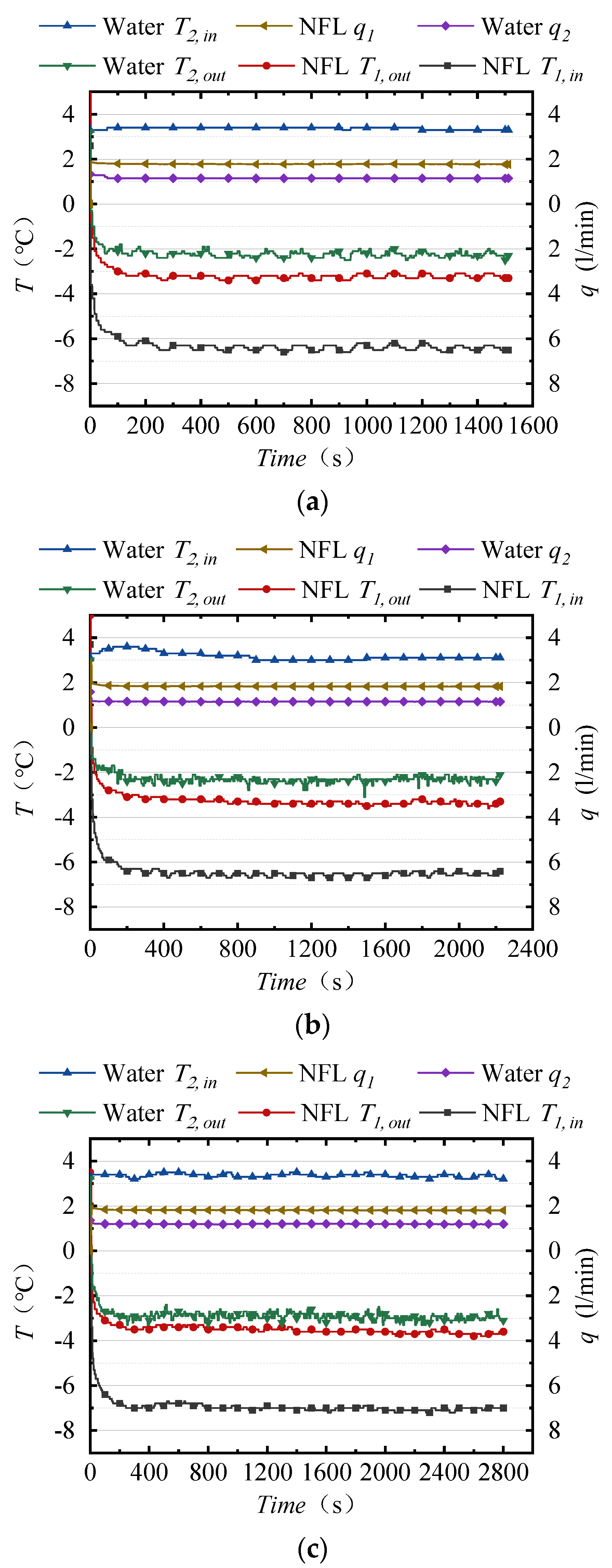
3.1.1. Subcooled Water with Different Subcooling Degrees

The magnitude of the subcooling degree of the subcooled water determines the ease of its conversion into ice or ice slurry after release through subcooling. The greater the subcooling degree is, the higher the energy (latent heat) will be, and the easier it will be to release the subcooled water through small perturbations. Figure 3 shows the experimental results of four subcooling degrees achieved according to the experimental conditions. The results illustrate that the compact heat exchanger is suitable for the dynamic generation of subcooled water, and Figure 3a shows that the system reached the higher level of current subcooled water engineering applications for dynamic ice storage systems (2 K) [7,22]. Any 0.1 K increase in the subcooling degree is difficult to achieve. Figure 3b–d show our explorations aiming to continuously increase the subcooling degrees and duration time, according to which the subcooling degree increases by 1.5 K compared to Figure 3a. Additionally, the system can maintain stable subcooled water generation for a certain period under the experimental conditions shown in Figure 3b,c. Under the experimental conditions in Figure 3d, the subcooling degree reaches 3.6 K. At subcooling degrees no greater than 3 K, the relative duration of the water’s subcooling is longer. At more than 3.5 K, the duration decreases. Compared with the previous three results, this demonstrates that it is easier to convert water into ice or ice slurry after releasing the subcooled water, while the duration time is significantly shorter, and heat exchange channel blockage occurs earlier and more frequently.
The high frequency of fluctuations in the outlet water temperature is an impact of the inlet temperature (thermostatic accuracy) and K-type thermocouple temperature measurement of the outlet water temperature (small changes in the direction of water flow). This has an effect on the increase in the subcooling degree and the duration. During the dynamic generation of the supercooled water, fluctuations in the inlet parameters cause simultaneous changes in the outlet parameters, whereby the inlet temperature parameters vary more than the flow rate. This occurs as a result of the combined effects of the accuracy of the thermostatic device for both loop sides and heat loss in the pipeline due to environmental changes. Therefore, the subcooled water must undergo a non-constant process of temperature fluctuation with time from the beginning of the process to the constant generation stage, which lasts for approximately 180 s. The parameters of the experiments undergo minor changes as the subcooled temperature enters the constant generation stage.
In this experimental study, the dynamically generated subcooled water was disturbed by the energy of the free-falling impact and ice slurry formed after the release of the subcooled water. Stalactite-like icicles formed as part of the continuous accumulation of the subcooled water. Their properties were soft and mud-like, and they contained water. As shown in Figure 4, the upper part of the icicles was drier and resembled snow, while the lower part consisted of a high water content, possessing a dark color and being ice-like. The experiment was conducted during summer, no air-conditioning system was set up, and the ice storage tank was insulated, even though it was a low-temperature environment. The generated ice or ice slurry partially melts, thus maintaining the low-temperature conditions in the tank. Ice slurry generation requires two conditions: the subcooling degree and the duration. Only when the temperature inside the ice storage tank falls below 0 °C will a large number of tiny ice crystals form in the stored subcooled water at the bottom of the tank, growing and accumulating over time. Here, we paid attention and aimed to control the amount of subcooled water in the tank, not only to ensure a large degree of accumulation, but because impact with the ice layer is more likely to result in release through subcooling. The ice slurry will be scattered when there is too much water, and the extraction of subcooled water from the ice storage tank will be interspersed, causing a loss of ice slurry, which can easily lead to freezing in the pipe. When the subcooling degree is 3 K or above, it is observed that ice crystals form more easily, ice slurry accumulates faster, and there is less ice or ice slurry to melt in order to maintain the low temperature. In brief, the greater the degree of subcooling is, the more easily ice or ice slurry forms, the longer it lasts, and the more ice is formed.

3.1.2. Maximum Degree of Subcooling and Maximum Duration Time

Figure 5a,b presents the maximum subcooling temperature of 3.8 K obtained in the experiment and the maximum duration time of 108 min obtained at an average subcooling temperature of 2.8 K, respectively. When the inlet temperature of the tap water is 3.1 °C and the flow rate into the heat exchanger is 1.140 L/min, the inlet temperature of the NFL is adjusted to −8.1 °C, and the flow rate is 1.780 L/min. The inlet and outlet temperatures of the tap water change by 6.9 K, and the maximum subcooling degree of the subcooled water reaches 3.8 K. This result is superior to that of experiments conducted using pure water, with only a 3.8 K change in the inlet and outlet temperature difference and a 3.3 K subcooling temperature in comparison to the double-tube heat exchanger [6]. In the dynamic generation of subcooled water, all the parameters remained in a dynamic equilibrium, with small fluctuations for the first 350 s. After that, the generation of subcooled water ceased due to a certain drop in the NFL temperature, which induced the occurrence of ice blockage. Under these conditions, the ultimate subcooling degree (3.8 K) of this compact heat exchanger was reached.
When the tap water has an inlet temperature of 3.2 °C and a flow rate into the heat exchanger of 1.182 L/min, the inlet temperature of the NFL is adjusted t o −6.8 °C, with a flow rate of 1.821 L/min. The temperature difference between the tap water inlet and outlet changes by 6.0 K, and the average temperature of −2.8 °C of the subcooled water lasts for 108 min. Compared with the experimental results for subcooled water using a plate heat exchanger [23], this study shows significant enhancements in the indicators of the tap water inlet and outlet temperature change and achieved a suitable subcooling degree, with the duration remaining to be improved. At a 2.8 K subcooling degree, the changes in all the parameters in the long dynamic generation process were more easily visualized. For the period of time before dynamic generation ceased, there was a continuous drop in the temperature of the NFL, which may have disrupted the heat transfer equilibrium and caused the freezing of the heat transfer channels. The dynamically generated subcooled water, after release through subcooling, generated a certain amount of ice slurry. Whether at 2.8 K or 3.8 K, the freezing of the compact heat exchanger channels was instantaneous when ice blockage occurred.

3.1.3. Influence of Specific Flux i

When considering the condition settings for the dynamic generation of subcooled water, the flow rate suitable for the dynamic generation of subcooled water in a compact heat exchanger is investigated according to the energy conservation relationship. To reduce the parameter variables, the specific flux i and the working fluid temperature difference between the two sides of the heat exchanger are taken as the objects of analysis, where the specific flux i is the ratio of the flow rate of NFL to tap water. For each of the different subcooling degrees (2 K, 2.5 K, 3 K), 30 experimental data sets are taken. For either tap water or NFL, a slight change in the flow rate at the inlet will cause a change in the temperature of the inlet and outlet on both sides of the heat exchanger, i.e., a change in the temperature difference. When the flow rate ratio is set in the range of 1.3~1.9, the temperature change of the tap water between the inlet and outlet of the heat exchanger is between 5 and 6 K, and that of the NFL is between 3 and 4 K, as shown in Figure 6. When the subcooling degree of the subcooled water increases, i tends to change more slowly, while for the working fluid moving in and out of the heat exchanger, the change in the temperature difference also slows. This occurrence indicates that as the subcooling degree increases, the range of suitable tap water flow is reduced. When the flow rate is high, the disturbance is large; when the flow rate is low, the time of flow through the heat exchanger increases, and this also increases the level of uncertainty and the ice nucleus growth time. Therefore, it is necessary to choose the most suitable specific flux size. As can be seen in Figure 6, ideal specific flux i for a large subcooling degree in the dynamic generation of subcooled water is around 1.5.

3.2. Analysis of Ice Blockage Factors

As shown in Table 3, the results of a total of 88 experiments were classified in terms of the subcooling degree shown when 5 min of dynamic generation of supercooled water was used as the threshold time. As the subcooling degrees increase, the maximum durations decrease, and the number of experimental samples meeting the requirements also decreases, indicating that the increasing subcooling degrees promote the formation of ice nuclei. In the above classification of the experimental results, some experiments have different durations, even under the same conditions, indicating the randomness of ice blockage occurrence during the dynamic generation of subcooled water. The possible factors are as follows: (1) The increase in the subcooling degrees may likely cause the growth and rapid spread of ice embryos formed by impure substances in tap water. (2) Due to the heat exchanger structure, there is a possibility that the two turns on the water side of the heat exchanger outlet channel ① ② will cause an energy disturbance. Thus, this excites the formation of ice nuclei and the aggregation of ice nuclei, resulting in ice blockage in the heat exchanger channels, as shown in Figure 7.
The above experimental results show that using a compact heat exchanger to reduce the passage time of the working fluid in its channels may result in greater subcooling and a longer duration than those of other heat exchangers. Since the subcooled water tends to freeze instantaneously due to certain conditions causing ice nuclei to form, ice blockage can occur after the formation of the subcooled water with the tap water. The greater the subcooling degrees are, the faster the growth of ice nuclei due to the diffusion of latent heat will be. The subcooled water in the heat exchanger channels is prone to instantaneous icing caused by a slight, sudden energy disturbance, causing the occurrence of ice blockage. In our exploration on the increase in the subcooling degrees, the heat exchanger surface and the outer wall of the waterway outlet sometimes showed a trace of ice that was almost imperceptible. This trace of ice, formed due to a small energy disturbance, may induce ice blockage (providing the ice nuclei) [24]. Whenever the generation of subcooled water stops, the water channels of the heat exchanger will freeze almost instantaneously. A mixture of ice and water was found at the outlet of the heat exchanger, which may be presumed to be an excess distribution of impure substances in the water in a particular water channel, causing the phenomenon of intensive formation of ice nuclei, as shown in the detailed diagram of ① in Figure 7. Therefore, the use of multiple channel groups to disperse impurities in the tap water and cause them to flow out of the heat exchanger channels before the completion of the diffusion of latent heat (i.e., further reducing the channel length l s and hydraulic diameter d i , increasing the number of layers, and eliminating the two turns of the water outlet), as well as the minimization of slight, unnecessary energy disturbance in the heat exchanger channels, may be an effective means to achieve a lower temperature through the cooling of the water and reduce the risk of ice blockage.

3.3. Discussion

In the controlled experimental setting, in which we aimed to increase the subcooling degrees of tap water and tried to extend the dynamic generation of subcooled water, the inlet temperature of the tap water in the heat exchanger was set at 3.0 °C, with minor changes occurring consistently in the measurement of the inlet water temperature of the heat exchanger due to the fact that the pipeline from the thermostatic device to the inlet of the heat exchanger was affected by changes in the ambient temperature and flow rate. The small changes in the water temperature of the heat exchanger inlet and the setting of the non-freezing liquid temperature are necessarily related. If the subcooled water reaches the maximum subcooling degree under a given condition, a decrease in the inlet temperature on either side of the two loops may cause an ice blockage. Such small temperature and flow fluctuations can periodically change the outlet water temperature, which may cause an energy disturbance in the channels and cause an ice blockage. Therefore, it is critical to have a relatively uniform and high-precision temperature when tap water and NFL enter the heat exchanger.
Figure 6 shows that in the statistics of different subcooling degrees, i varies in a range of less than 1. When the subcooling degrees increase, there is a tendency towards decline with the variation in the inlet and outlet temperature difference, regardless of whether tap water or NFL is applied. From the correlation of the experimental results, we can conclude that to achieve a greater subcooling degree, both the tap water and NFL in the heat exchanger inlet must maintain a uniform temperature and flow rate (or both sides of the inlet temperature must be synchronized with the exact amplitude change, although the amplitude should be as small as possible, with a low change frequency).
In future experimental setups, the inlet sections on both sides of the heat exchanger will require pipeline insulation treatment. Thus, to ensure that the inlet fluid temperature is as equal as possible to the temperature set by the thermostatic device for both sides, it is necessary for the inlet added to the mixing device for ensuring the temperature uniformity and flow fluctuations.

4. Conclusions

This paper discussed experiments involving a compact heat exchanger with a high heat transfer performance, small hydraulic diameter, and extremely short heat transfer channels to build a dynamic generation setup for subcooled water. The generation conditions and control methods for high subcooling degrees and long durations were explored using tap water and non-freezing liquid as working fluids. The conclusions are as follows:
(1)
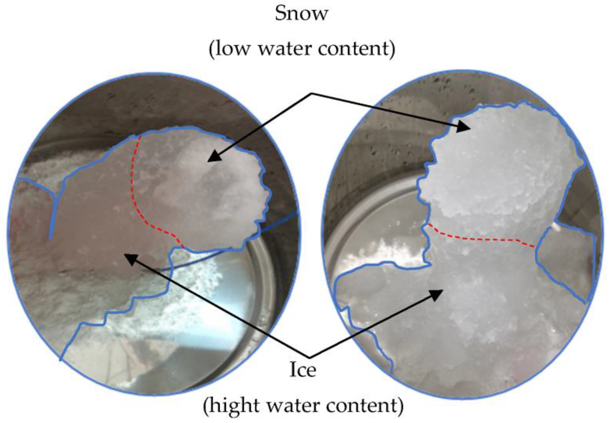
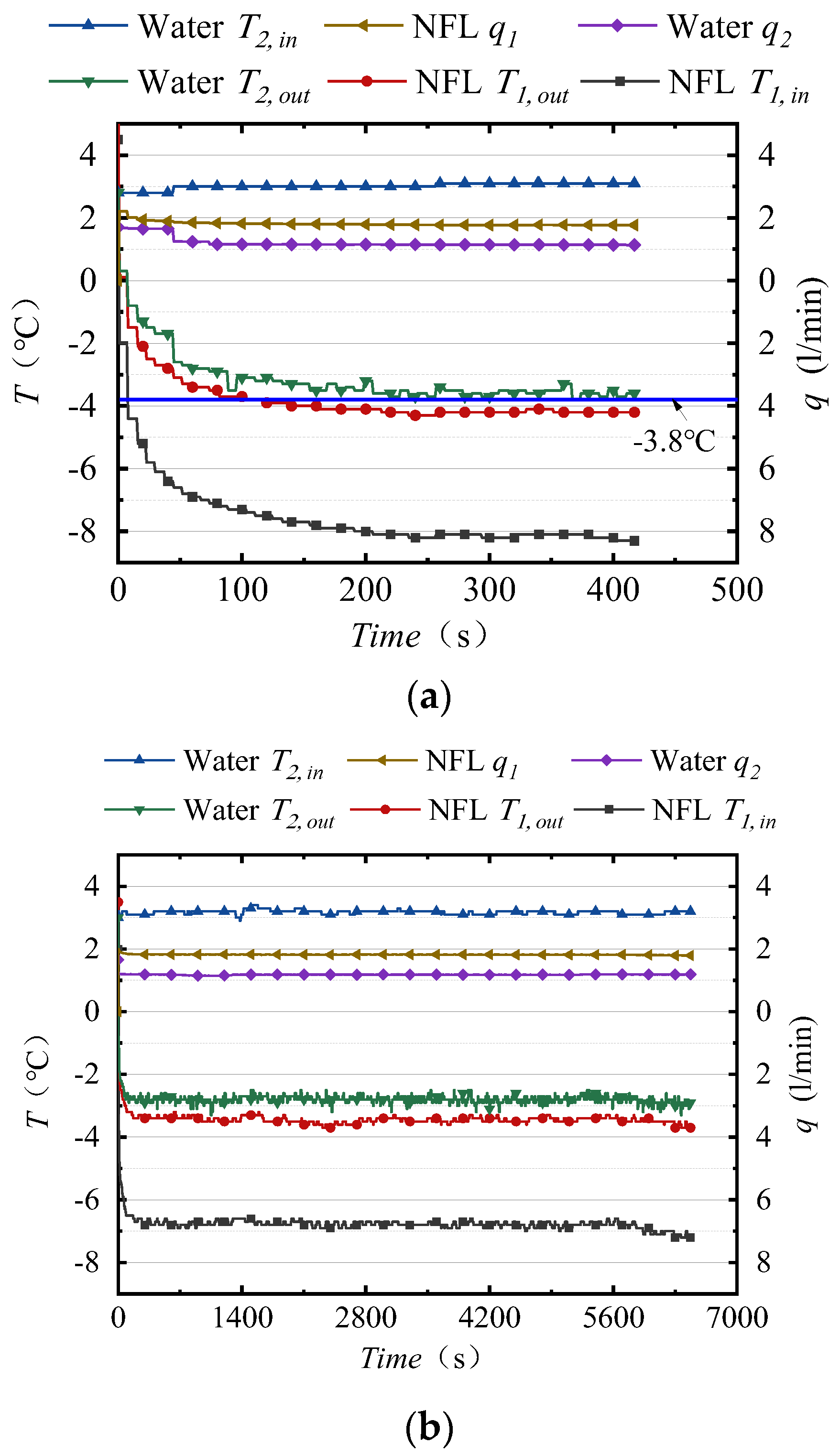
The dynamic generation of subcooled water with a high subcooling degree from tap water is feasible. The generation of ice or ice slurry through this processes shows the system’s potential for applications in food engineering, indoor snowmaking, ice storage, and other fields. The experiments also proved that the compact heat exchanger is suitable for the dynamic generation of subcooled water. The concept of using the high-efficiency heat transfer performance of the compact heat exchanger for instantaneous heat transfer and shortening the channel length and small hydraulic diameter is also correct. Through the experiments, we achieved the generation of subcooled water at a minimum of −3.8 °C, and the −2.8 °C average-temperature subcooled water generation lasted for 108 min.
(2)
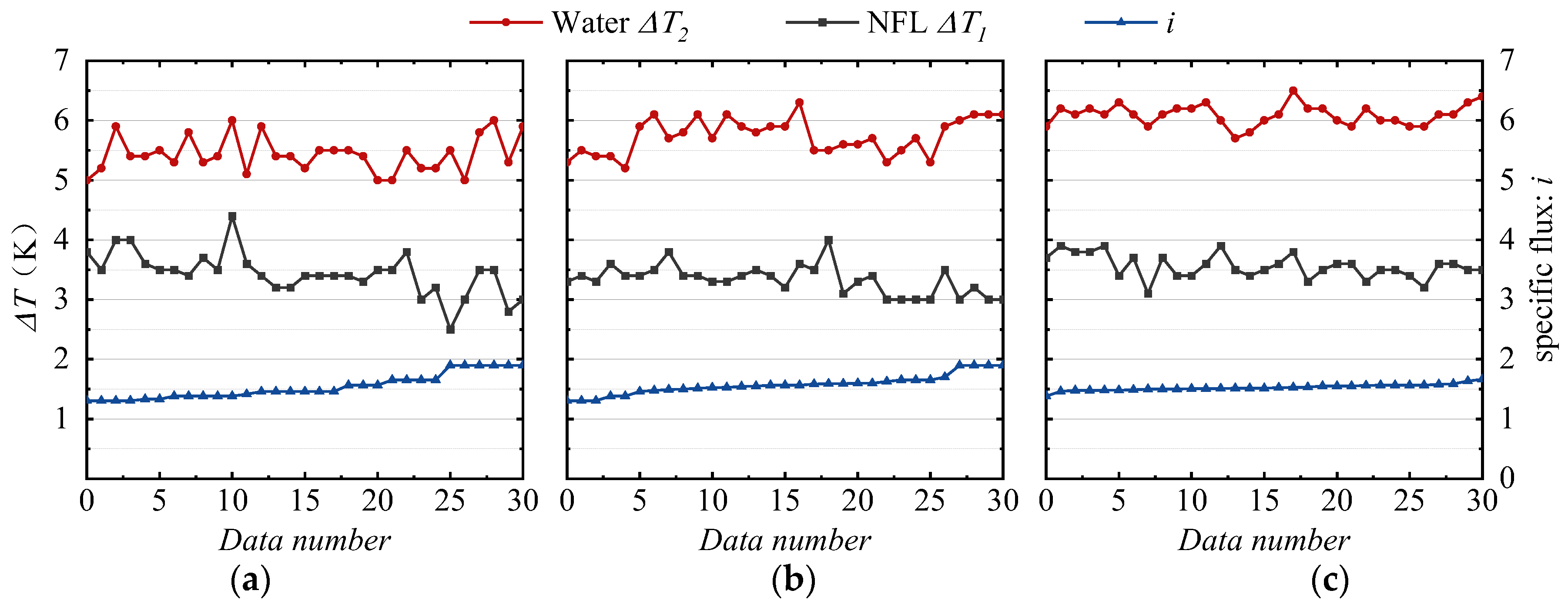
The deployment of compact heat exchangers can achieve higher inlet water temperatures, greater subcooling degrees, and longer dynamic generation durations than the use of other types of heat exchangers. With the increase in the subcooling degree, the range of specific flux i suitable for the dynamic generation of subcooled water is narrowed, and a specific flux i of around 1.5 is more appropriate. The increase in the subcooling degree is more effective in releasing the subcooled water to form ice or ice slurry. The dynamic generation durations of the subcooled water determine the amount of ice produced.
(3)
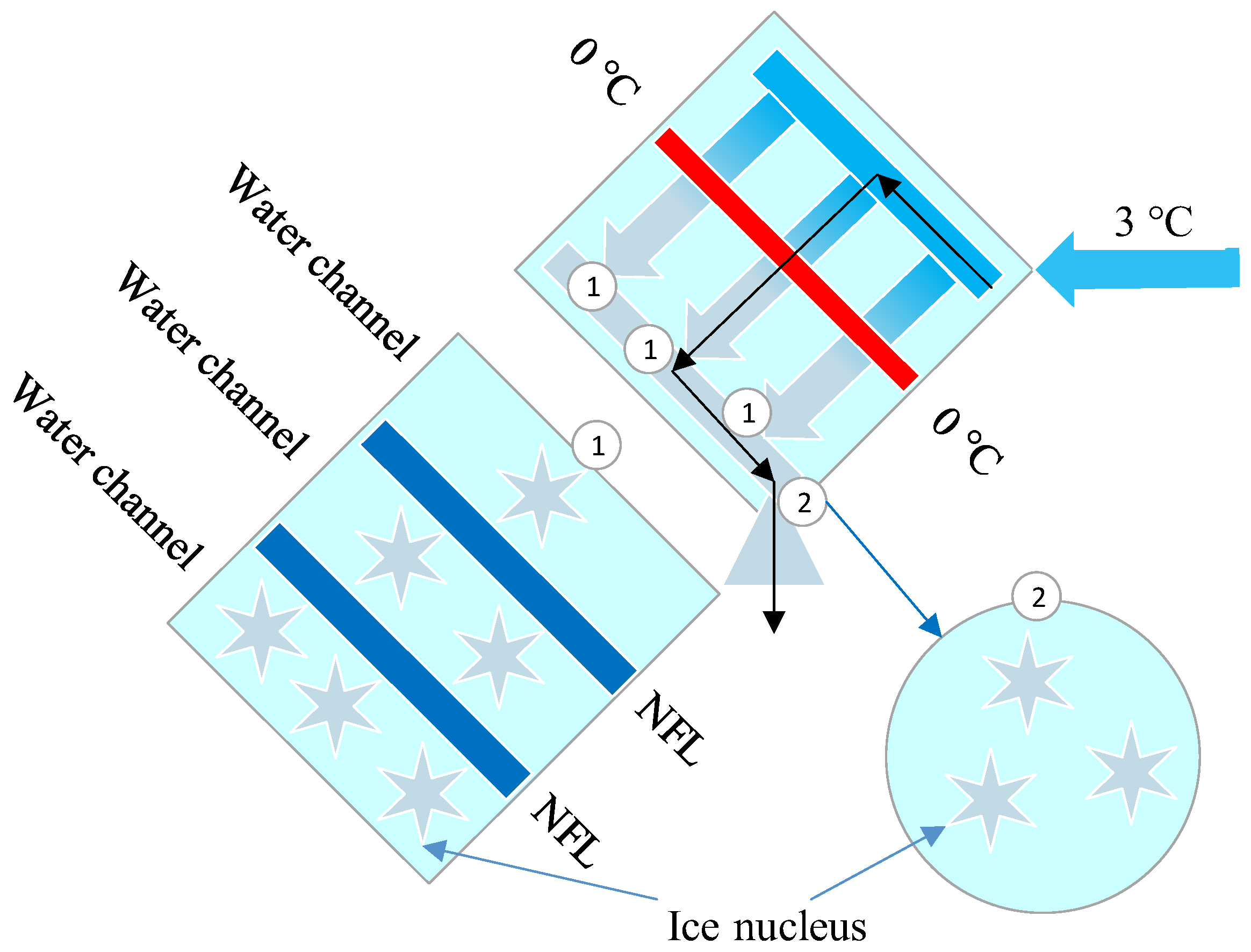
Ice blockage also occurs when generating subcooled water with tap water using a compact heat exchanger. The reasons for ice blockage are as follows: (1) the impure particles in the tap water are more likely to promote the formation of ice nuclei at high subcooling degrees; (2) the micro-icing on the surface of the compact heat exchanger may provide ice nuclei for the subcooled water at the outlet; and (3) the two turns at the outlet of the compact heat exchanger may also cause minor energy disturbance affecting the subcooled water flowing out of the heat exchanger for release through subcooling, especially at high subcooling degrees at which ice blockage is more likely to occur.
(4)
The analysis of the results clarified that compact heat exchangers for the dynamic generation of subcooled water require further design guidelines to shorten the channels, reduce the hydraulic diameter, optimize the shape of the channels, and increase the number of channels. In addition, the heat exchanger’s surface structure prevents icing and achieves greater subcooling degrees, laying a foundation for later explorations of the dynamic generation of deep subcooled water.

Author Contributions

Software, S.S.; Investigation, K.W.; Writing—review & editing, P.C. All authors have read and agreed to the published version of the manuscript.

Funding

This research received no external funding.

Institutional Review Board Statement

Not applicable.

Informed Consent Statement

Not applicable.

Data Availability Statement

Not applicable.

Acknowledgments

The authors are grateful to Jinhong Chen of Zhejiang Xuebolan Technology Co., Ltd., for his financial and technical support, and Li Zhang for her help in this research.

Conflicts of Interest

The authors declare no conflict of interest.

Nomenclature

NFLnon-freezing liquid
tduration time of subcooled water (min)
Ttemperature (°C)
ΔTheat exchange temperature difference (K)
T1,inNFL inlet temperature (°C)
T1,outNFL outlet temperature (°C)
ΔT1NFL ΔT (K)
T2,intap water inlet temperature (°C)
T2,outtap water outlet temperature (°C)
ΔT2tap water ΔT (K)
qvolume flow (L/min)
q1NFL volume flow (L/min)
q2tap water volume flow (L/min)
ispecific flux (q1/q2)
Tffreezing temperature of the water
Tw1inner surface temperature of the subcooled tube
Tb1temperature of the water at the subcooled water outlet
lsdistance from the position where the average temperature of the test fluid reaches the freezing temperature to the cooling tube exit
dihydraulic diameter
PrPrandtl number
ReReynolds number
θfdimensionless subcooling degree
Gz*Graetz number
Cfwall friction
NuNusselt number

References

  1. Hu, R.; Zhang, C.; Zhang, X.; Yang, L. Research status of supercooled water ice making: A review. J. Mol. Liq. 2022, 347, 118334. [Google Scholar] [CrossRef]
  2. Li, X.; Wu, W.; Li, K.; Ren, X.; Wang, Z. Experimental study on a wet precooling system for fruit and vegetables with ice slurry. Int. J. Refrig. 2022, 133, 9–18. [Google Scholar] [CrossRef]
  3. Cao, S.; Zhang, W.; Liu, A. Analysis of the development of ice slurry ice storage. China’s New Technol. New Prod. 2021, 5, 65–67. [Google Scholar]
  4. Daisuke, M. Ice Manufacturing Method and Sherbet-Like Ice. Japan Patent 26307, 2 February 2017. p. 10. [Google Scholar]
  5. Moriya, M.; Tanino, M.; Kikuchi, S.; Hayashi, T.; Okonogi, Y. Kozawa. An Ice Storage System using Supercooled Water 1st Report: Stable Control of Supercooling Water and Ice Making. Trans. Jpn. Soc. Refrig. Air Cond. Eng. 1995, 12, 253–262. [Google Scholar]
  6. Qu, K.; Jiang, Y. High-performance continuous ice-making system with supercooled water. Acta Sol. Energy 2002, 3, 317–321. [Google Scholar]
  7. Nagaishi, H.; Inada, T.; Yoshioka, T.; Sato, A. Development of a compact, onboard slurry icemaker to rapidly produce optimal ice for maintaining freshness of marine products. Synth. Engl. Ed. 2017, 10, 1–10. [Google Scholar]
  8. Wang, H. Theoretical and Experimental Research on Dynamic Ice Making in Supercooled Water Based on Nano-Fluorocarbon Coating Materials. Ph.D. Thesis, Huazhong University of Science and Technology, Wuhan, China, 2013. [Google Scholar]
  9. He, G.; Wu, R.; Liu, F. Experimental Design and Analysis of Preparation of Ice Slurry by Supercooled Water Method. Cryog. Supercond. 2006, 4, 303–307. [Google Scholar]
  10. Zhang, C.; Yang, L.; Lin, W.; Wei, J.; Guo, F. Performance Enhancement and Life-Cycle Cost Savings of Supercooled Water Ice Slurry Generation Systems Using Heat Regeneration. Sustainability 2022, 14, 3836. [Google Scholar] [CrossRef]
  11. Inaba, H.; Takeya, K.; Nozu, S. Fundamental Study on Continuous Ice Making Using Flowing Supercooled Water. Trans. Jpn. Soc. Mech. Eng. Ser. B 1992, 58, 1321–1328. [Google Scholar] [CrossRef] [Green Version]
  12. Kumano, H.; Morimoto, T.; Kimata, H. Initial and layered solidification behavior of an ice slurry under laminar and turbulent flow in a rectangular channel. Int. J. Refrig. 2022, 145, 1–9. [Google Scholar] [CrossRef]
  13. Qu, K.; Jiang, Y. Experimental study on the randomness of freezing of still supercooled water on stainless steel surface. Chin. J. Refrig. 2000, 4, 8–12. [Google Scholar]
  14. Inaba, H.; Miyahara, S.; Takeya, K. Fundamental Study on Continuous Ice Making in a Circular Tube by Flowing Water Solution. Trans. Jpn. Soc. Mech. Eng. Ser. B 1995, 61, 3296–3303. [Google Scholar] [CrossRef] [Green Version]
  15. Lv, Y.; Zhang, X.; Zou, L. Research progress on the effect of additives on ice slurry. Heat Mass Transf. 2022, 58, 1279–1287. [Google Scholar] [CrossRef]
  16. Wang, K.; Kentaro, S. Compact Heat Exchanger. JSRAE 2022, 98, 77–80. [Google Scholar]
  17. Yutaka, S.; Masao, F. Compact Heat Exchanger; Daily Newspaper: Tokyo, Japan, 1992. [Google Scholar]
  18. Mishima, O.; Stanley, H.E. The relationship between liquid, supercooled and glassy water. Nature 1998, 396, 329–335. [Google Scholar] [CrossRef]
  19. Fletcher, N. The Chemical Physics of Ice; Cambridge University Press: Cambridge, UK, 1970; p. 74. [Google Scholar]
  20. Inaba, H.; Lee, D.-W.; Horibe, A. Study on the critical conditions of ice formation for a continuous ice making system in a cooling pipe. Heat Transf.—Jpn. Res. 1998, 27, 74–83. [Google Scholar] [CrossRef]
  21. Zhang, P.; Lv, F.Y. A review of the recent advances in superhydrophobic surfaces and the emerging energy-related applications. Energy 2015, 82, 1068–1087. [Google Scholar] [CrossRef]
  22. Tatsunori, M.; Akihiro, M. Apparatus for producing supercooled water and method for producing supercooled water. Japan Patent 138593, 22 August 2019. p. 13. [Google Scholar]
  23. Takahiro, O.; Yasuhiro, Y. Ice Making System Using Supercooled Water and Ice Making Method Using Supercooled Water. Japan Patent JP6028248B1, 16 November 2016. [Google Scholar]
  24. Daisuke, M. Method and Apparatus for Stabilizing Ice Making. Japan Patent 92356, 16 May 2013. p. 10. [Google Scholar]
Figure 1. The compact heat exchanger and schematic of convection heat transfer.
Applsci 13 04369 g001
Figure 2. Subcooled water generation setup. (a) Schematic of subcooled water generation setup. (b) Photo of subcooled water generation setup. ① Compact heat exchanger. ② (High-temperature) thermostatic device. ③ (Low-temperature) thermostatic device. ④ Computer. ⑤ K-type thermocouple. ⑥ Turbine flowmeter. ⑦ Data recorder. ⑧ Pressure gauge. ⑨ Filter. ⑩ Ice storage tank. ⑪ Ball valve. ⑫ Water pump.
Applsci 13 04369 g002
Figure 3. Experimental results. (a) −2.1 °C subcooled water. (b) −2.4 °C subcooled water. (c) −3 °C subcooled water. (d) −3.6 °C subcooled water.
Applsci 13 04369 g003aApplsci 13 04369 g003b
Figure 4. Columnar ice slurry generated by subcooled water.
Applsci 13 04369 g004
Figure 5. Maximum degree of subcooling and maximum duration t. (a) Subcooled water T2,out: −3.8 °C. (b) Duration t: 108 min.
Applsci 13 04369 g005
Figure 6. Heat transfer temperature difference ΔT and specific flux i at different outlet water temperatures T2,out. (a) T2,out: −2.0 °C. (b) T2,out: −2.5 °C. (c) T2,out: −3.0 °C.
Applsci 13 04369 g006
Figure 7. Schematic of ice nucleus formation in heat exchanger channels. ① and ② represent the locations that cause perturbations in the subcooled water such that ice nucleus are generated. The symbols of gray stars represent ice nucleus.
Applsci 13 04369 g007
Table 1. Sizes, materials, and working fluid of compact heat exchanger.
ItemUnitContent
Dimensionsmm40 L × 40 W × 12.6 H
Hydraulic diametermm0.32
Heat exchange channel lengthmm21.6
Working fluid-High temperature: tap water; low temperature: NFL
Rated flowL/min3.00 L/min, normal temperature
Material-SUS316L, mirror surface
Channel processing-Photoetching
Structural processing-Atomic diffusion bonding
Performance testing-Leakage: <10−10 Pa·m3/s; pressure > 6.9 MPa
Table 2. Experimental conditions.
ItemConditionRemark
Tap waterT2,in (°C)3.0
q2 (L/min)1.000~1.300Depending on cooling conditions
NFLT1,in (°C)−6.0, −6.5, −7.0, −8.0
q1 (L/min)1.900Determined by the inlet temperature T1,in
Table 3. Duration distribution.
Subcooling Degree/K2.4~2.82.9~3.33.4~3.8Remarks
Number of samples463111
Time range/min>10>16>25>10>16>25>10>16>25
Quantity21104 (108)1885 (46)311 (28)(Maximum duration/min)
Disclaimer/Publisher’s Note: The statements, opinions and data contained in all publications are solely those of the individual author(s) and contributor(s) and not of MDPI and/or the editor(s). MDPI and/or the editor(s) disclaim responsibility for any injury to people or property resulting from any ideas, methods, instructions or products referred to in the content.

