
Laser Irradiation on Limestone and Cracking: An Experimental Approach

Abstract
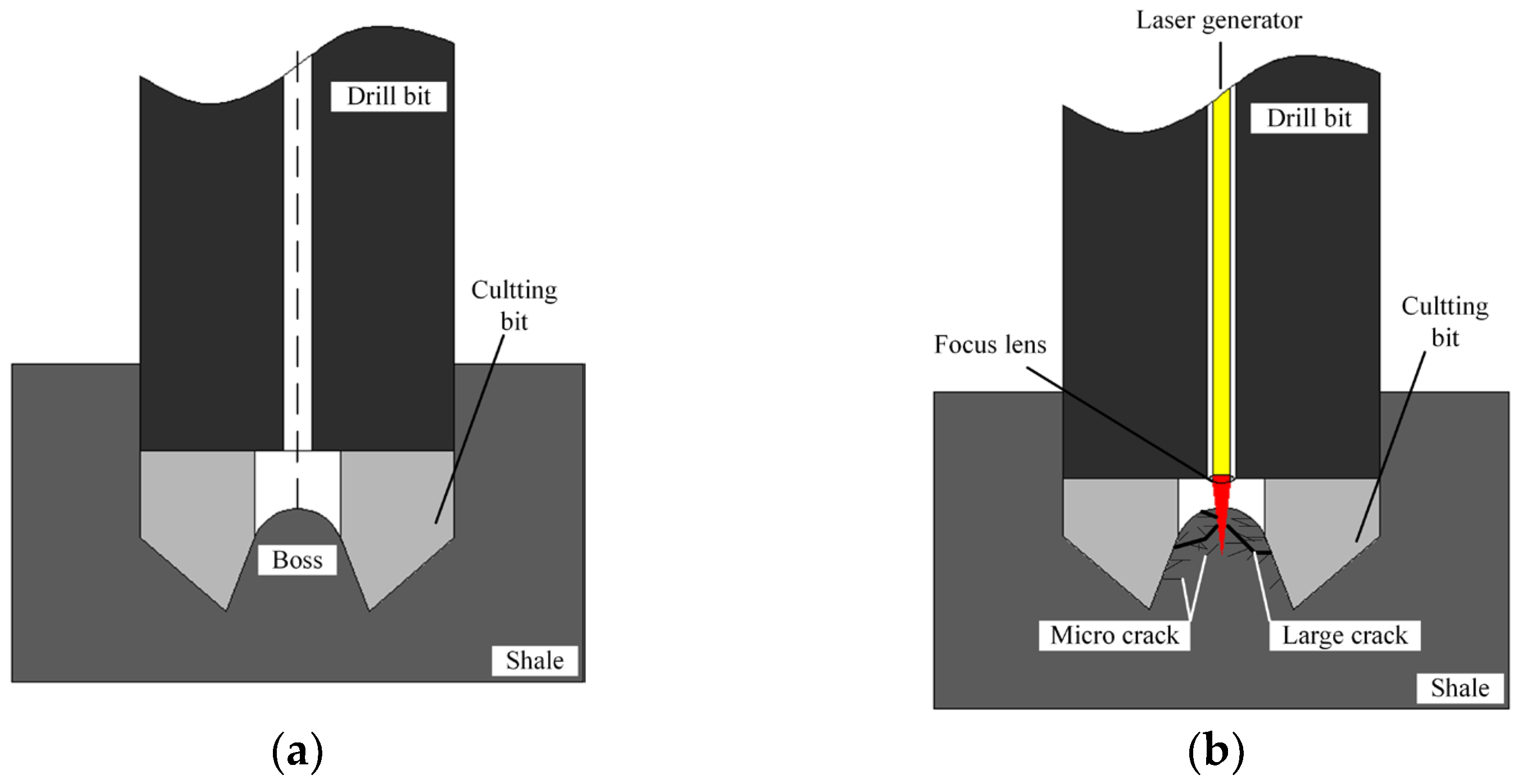
:1. Introduction
2. Experimental Procedure
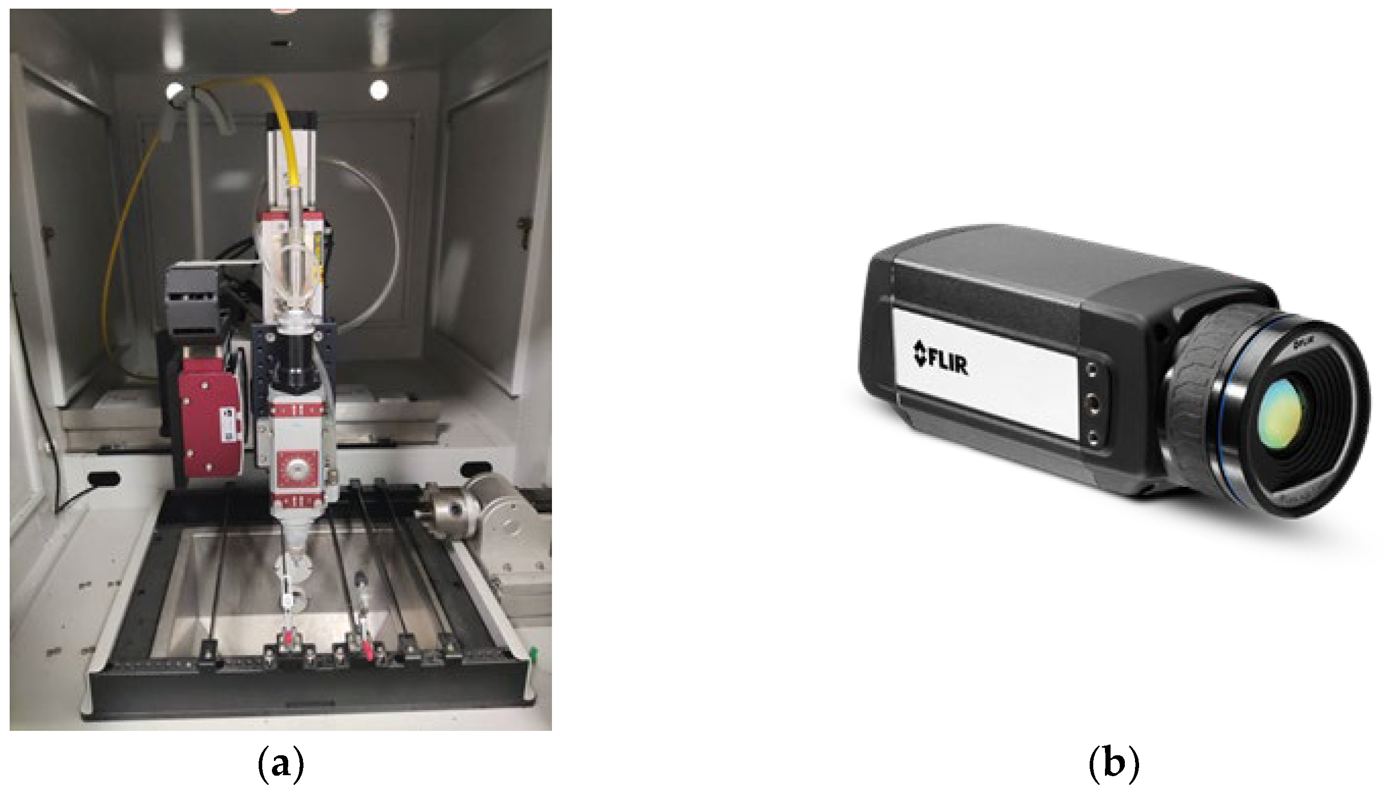
2.1. Apparatus
2.2. Experimental Scheme
3. Results
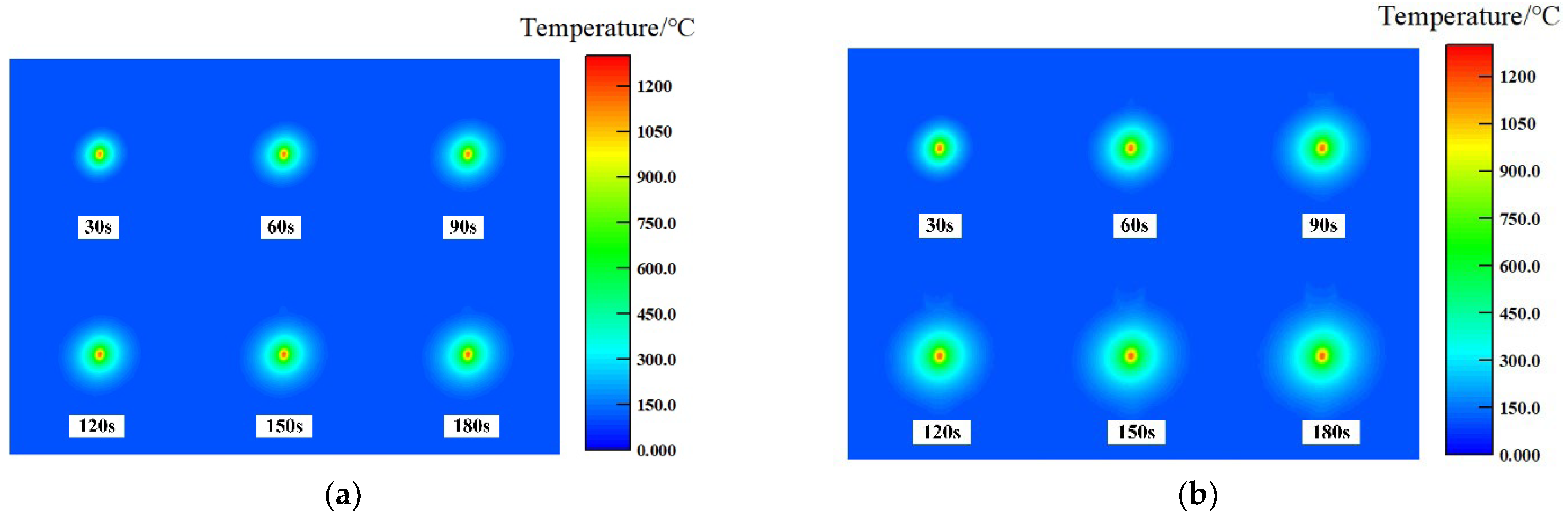
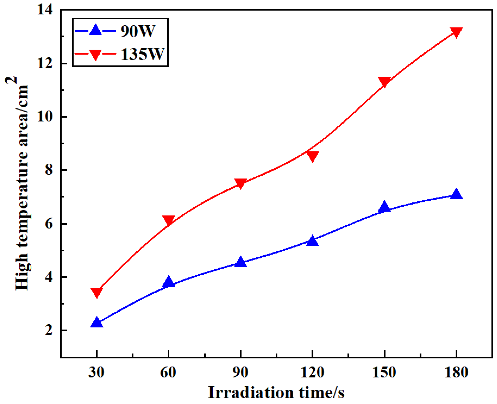
3.1. Temperature Distribution under Different Laser Power
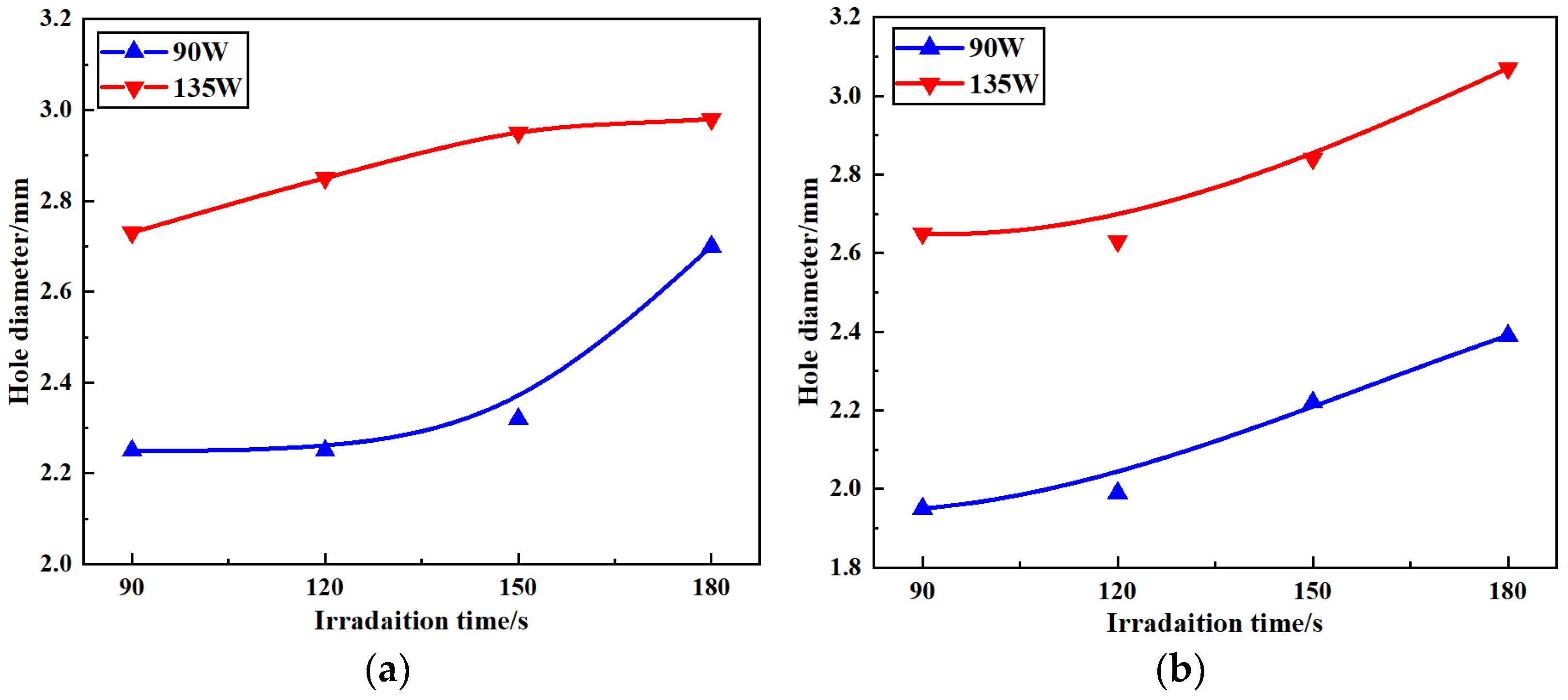
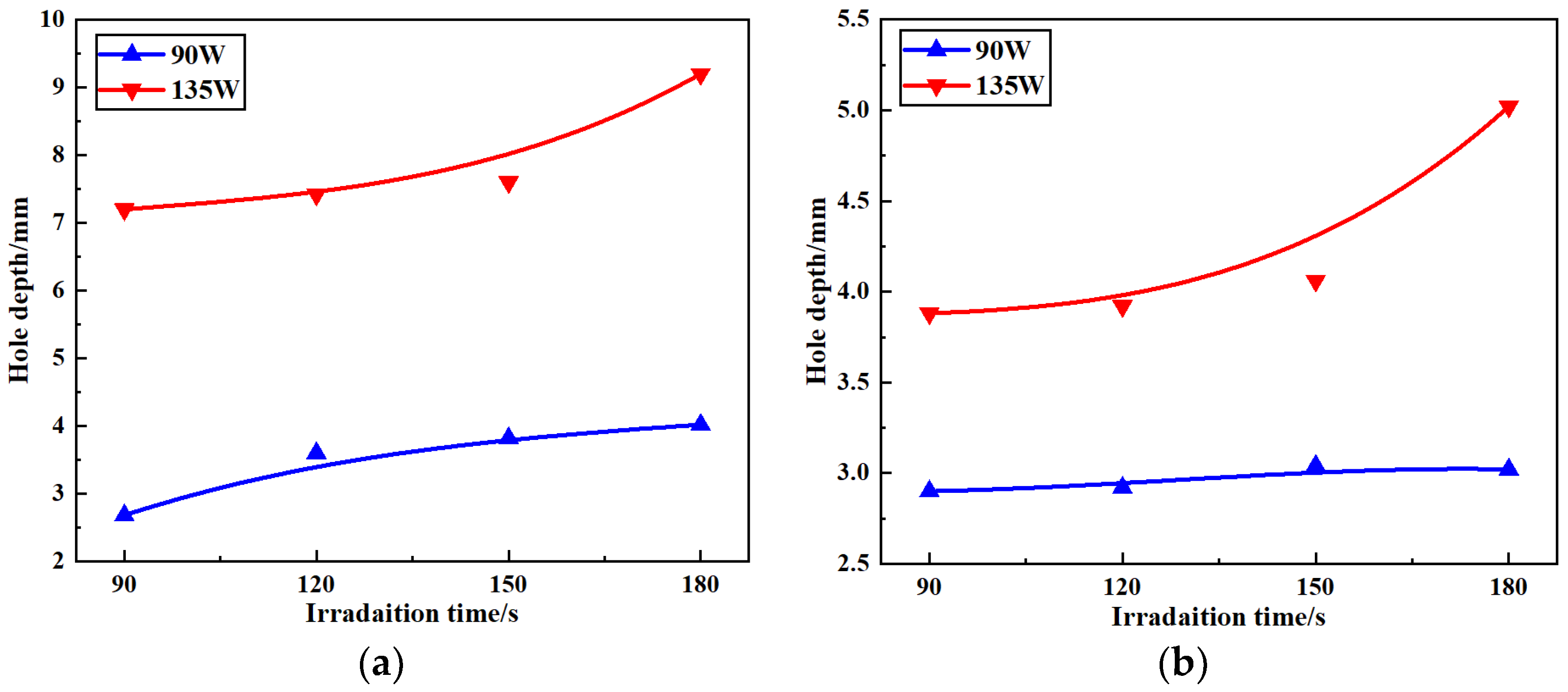
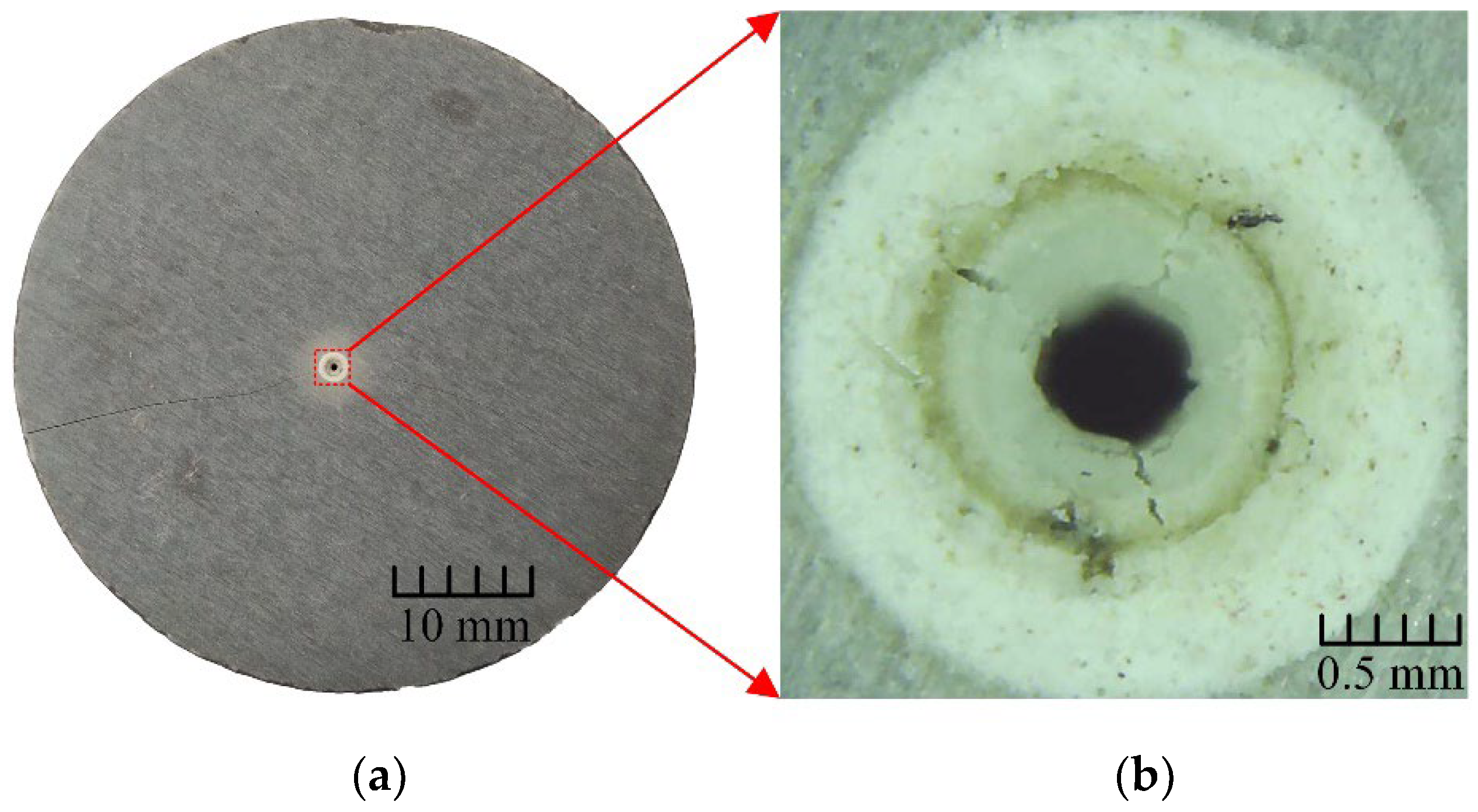
3.2. Analysis of Hole Size
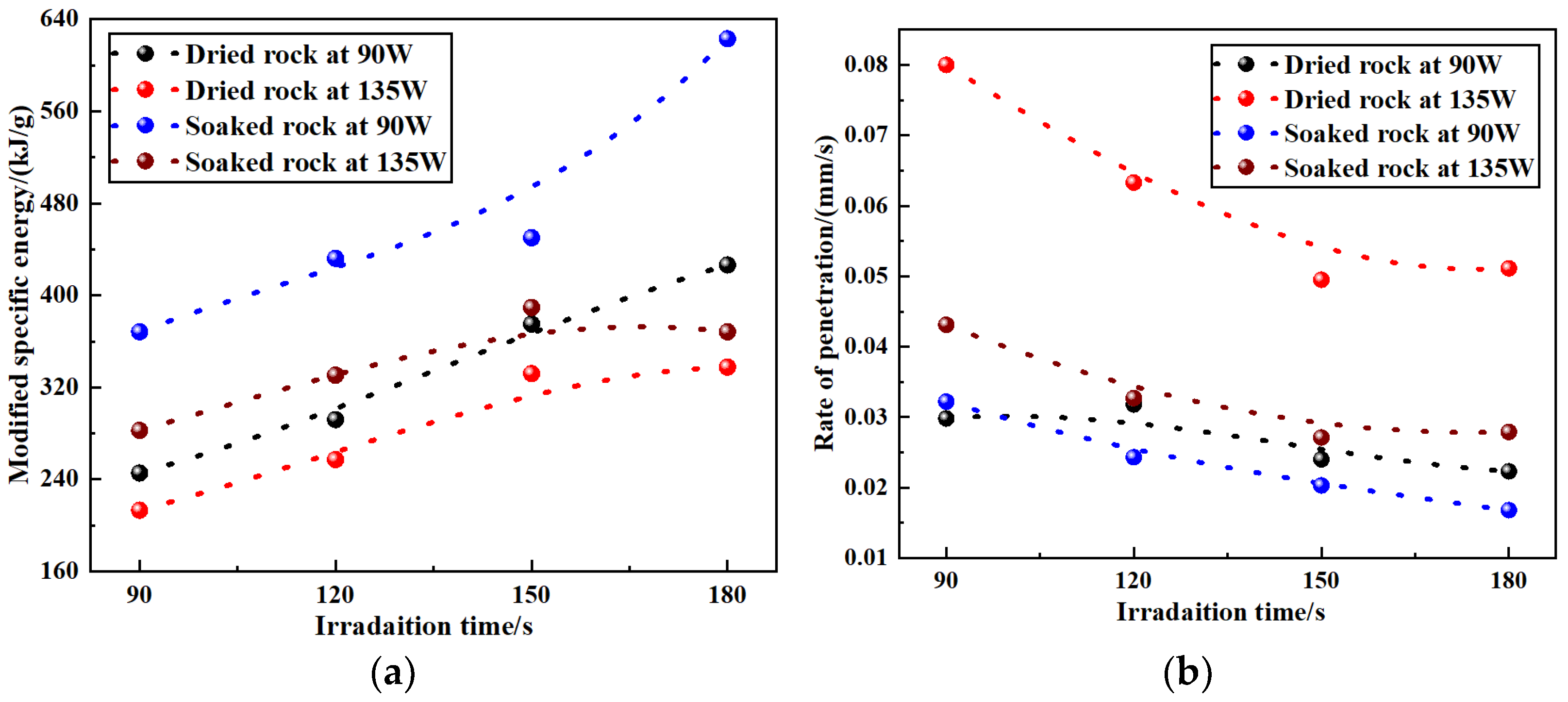
3.3. Efficiencies of Rock-Breaking under Laser Irradiation
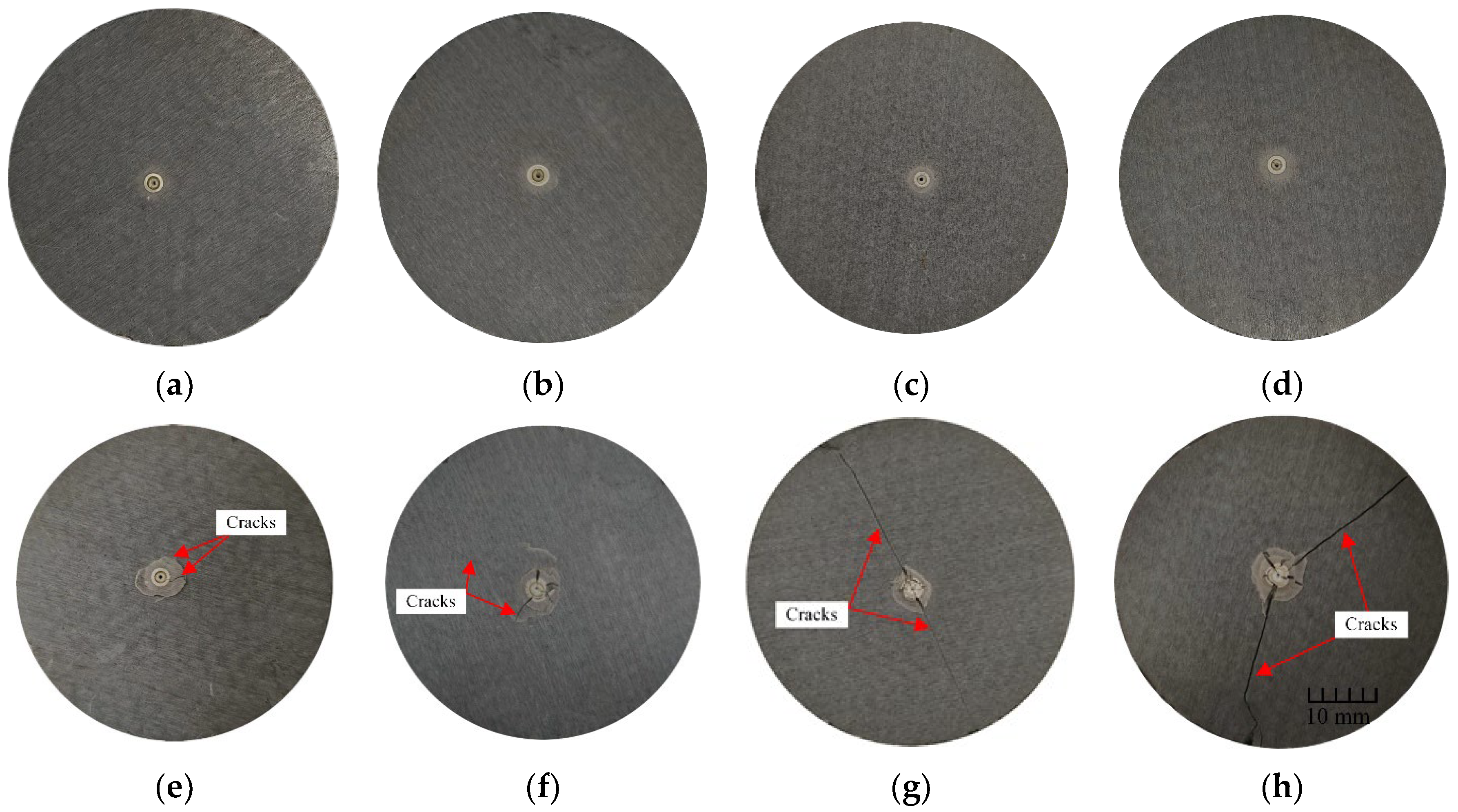
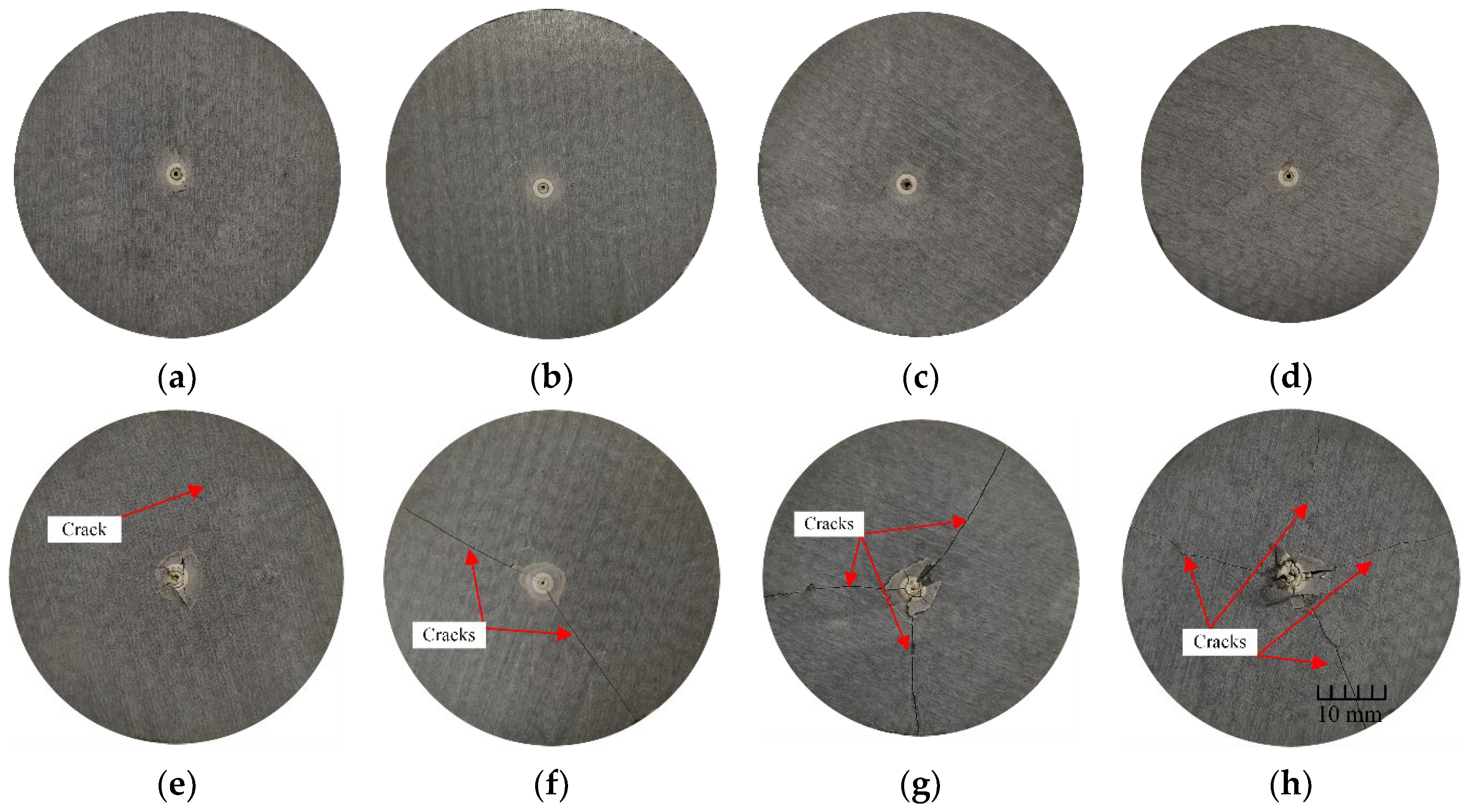
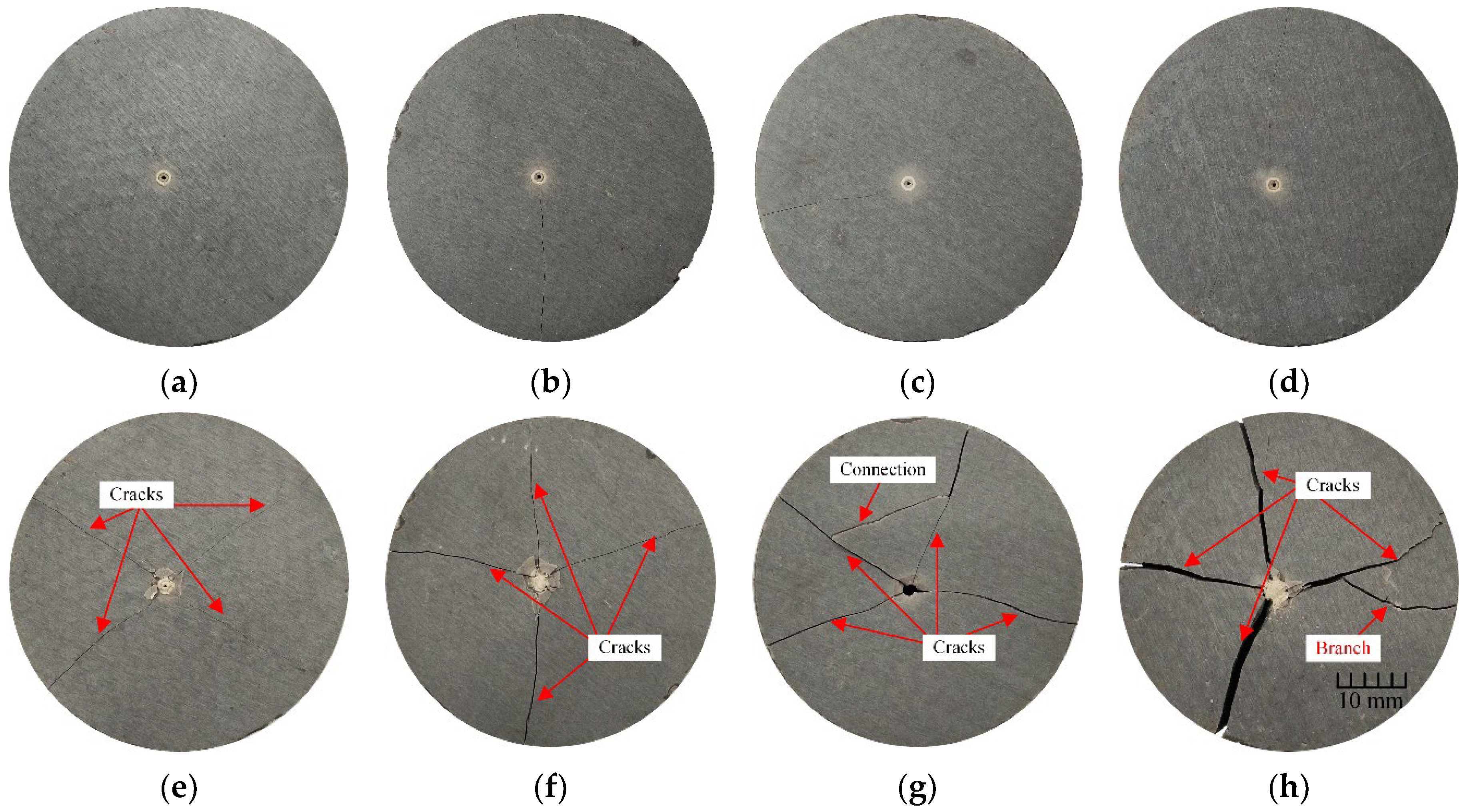
3.4. Micro-Fractures after Laser Irradiation
3.5. Variation of Fracture Length
4. Discussion
5. Conclusions
- (1)
- The temperature area over 100 °C increases with the increase of irradiation time and the one between 2.27 cm2 and 13.20 cm2 varies with the change of laser power between 90 W and 135 W. The specimen has a larger MSE and a smaller ROP at a power of 90 W compared with the 135 W, indicating that increasing the laser power improves the efficiency of rock-breaking. With the increase of the irradiation time, the MSE gradually increases, while the ROP gradually decreases;
- (2)
- The cracks on the surface of the rock samples developed considerably after being placed for one month. This is because the composition of limestone is dense, hard, and brittle. After the sample cools and shrinks, it is difficult for the cracks to be filled with cementitious substances, resulting in the continuous increase of the spacing and the gradual extension of the rock under the influence of its gravity;
- (3)
- The fracture length of the dried sample increased from 0.61 to 5.09 mm, and that of the soaked sample increased from 2.24 to 8.7 mm under a laser power of 90 W. The fracture length of the dried sample increased from 6.30 to 9.85 mm, and that of the soaked sample increased from 9.04 to 11.38 mm under a laser power of 135 W;
- (4)
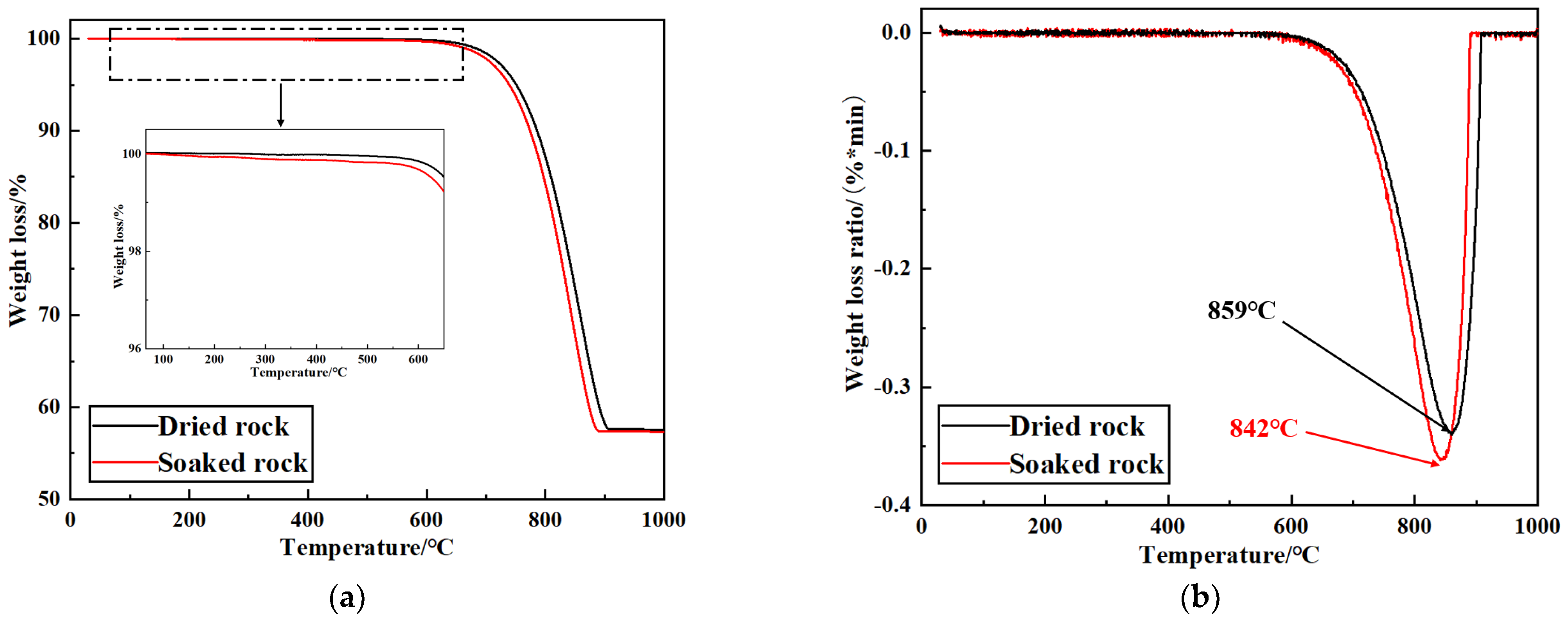
- The soaked sample began to show differences when heated at 100 °C, which was caused by the evaporation of some free water molecules in the rock. The main weight-loss temperatures of the samples occur in the range of 640 °C to 900 °C. This is because dolomite and calcite are thermally decomposed during the high temperature area. Inflection-point temperatures for the weight-loss ratio of soaked and dried samples were 842 °C and 859 °C, respectively.
Author Contributions
Funding
Institutional Review Board Statement
Informed Consent Statement
Data Availability Statement
Conflicts of Interest
References
- Rui, F.; Zhao, G.-F. Experimental and numerical investigation of laser-induced rock damage and the implications for laser-assisted rock cutting. Int. J. Rock Mech. Min. Sci. 2021, 139, 104653. [Google Scholar] [CrossRef]
- Yang, X.; Zhou, X.; Zhu, H.; Zhou, J.; Li, Y. Experimental Investigation on Hard Rock Breaking with Fiber Laser: Surface Failure Characteristics and Perforating Mechanism. Adv. Civ. Eng. 2020, 2020, 1316796. [Google Scholar] [CrossRef]
- Zhao, J.; Zhang, G.; Xu, Y.; Lin, A.; Zhao, J.; Yang, D. Enhancing rate of penetration in a tight formation with high-pressure water jet (HPWJ) via a downhole pressurized drilling tool. J. Pet. Sci. Eng. 2019, 174, 1194–1207. [Google Scholar] [CrossRef]
- Xiao, S.; Ren, Q.; Ge, Z.; Chen, B.; Wang, F. Study of the rock-breaking and drilling performance of a self-rotatory water-jet bit in water-jet drilling and its influential factors. Energy Sources Part A Recovery Util. Environ. Eff. 2020, 1, 1–17. [Google Scholar] [CrossRef]
- Olson, J.J.; Olson, K.S. ARPA-Bureau of Mines Rock Mechanics and Rapid Excavation Program. A Research Project Summary; Bureau of Mines: Pittsburgh, PA, USA, 1975.
- Lukawski, M.Z.; Anderson, B.J.; Augustine, C.; Capuano, L.E.; Beckers, K.F.; Livesay, B.; Tester, J.W. Cost analysis of oil, gas, and geothermal well drilling. J. Pet. Sci. Eng. 2014, 118, 1–14. [Google Scholar] [CrossRef]
- Nath, A.K. Laser Drilling of Metallic and Nonmetallic Substrates. In Comprehensive Materials Processing; Elsevier: Amsterdam, The Netherlands, 2014; pp. 115–175. [Google Scholar]
- Yang, Z.; Yi, X. Current Progresses on Laser Drilling Technology. Oil Field Equip. 2008, 37, 11–16. [Google Scholar]
- Hu, M.; Bai, Y.; Chen, H.; Lu, B.; Bai, J. Engineering characteristics of laser perforation with a high power fiber laser in oil and gas wells. Infrared Phys. Technol. 2018, 92, 103–108. [Google Scholar] [CrossRef]
- Wang, Y.; Jiang, J.; Darkwa, J.; Xu, Z.; Zheng, X.; Zhou, G. Experimental study of thermal fracturing of Hot Dry Rock irradiated by moving laser beam: Temperature, efficiency and porosity. Renew. Energy 2020, 160, 803–816. [Google Scholar] [CrossRef]
- Shin, J.S.; Oh, S.Y.; Park, S.; Park, H.; Kim, T.-S.; Lee, L.; Kim, Y.; Lee, J. Underwater laser cutting of stainless steel up to 100 mm thick for dismantling application in nuclear power plants. Ann. Nucl. Energy 2020, 147, 107655. [Google Scholar] [CrossRef]
- Xu, Z.; Reed, C.B.; Parker, R.A.; Gahan, B.C.; Figueroa, H. Laser rock drilling by a super-pulsed CO2 laser beam. In Proceedings of the 21st International Congress on Laser Materials Processing and Laser Microfabrication, Scottsdale, AZ, USA, 14–17 October 2002. [Google Scholar]
- Pan, H.; Hu, Y.; Kang, Y.; Chen, H.; Liu, F.; Xie, J.; Wang, X. The influence of laser irradiation parameters on thermal breaking characteristics of shale. J. Pet. Sci. Eng. 2022, 213, 110397. [Google Scholar] [CrossRef]
- Li, Q.; Zhai, Y.; Huang, Z.; Chen, K.; Zhang, W.; Liang, Y. Research on crack cracking mechanism and damage evaluation method of granite under laser action. Opt. Commun. 2022, 506, 127556. [Google Scholar] [CrossRef]
- Li, M.; Han, B.; Qi, C.; Wang, Y.; Song, L. Investigation on Nano-Self-Lubricant Coating Synthesized by Laser Cladding and Ion Sulfurization. J. Nanomater. 2015, 2015, 814038. [Google Scholar] [CrossRef] [Green Version]
- Fenech, M.; Mallia, B.; Grech, M.; Betts, J.C. Post-deposition heat treatment of co-deposited Cr3C2 and AISI 410 stainless steel using the coaxial laser deposition technique. J. Mater. Sci. 2012, 48, 2224–2235. [Google Scholar] [CrossRef]
- Graves, R.M.; O’Brien, D.G. StarWars Laser Technology Applied to Drilling and Completing Gas Wells. In Proceedings of the SPE Annual Technical Conference and Exhibition, New Orleans, LA, USA, 27–30 September 1998. [Google Scholar]
- Lu, Y.; Tang, J.; Ge, Z.; Xia, B.; Liu, Y. Hard rock drilling technique with abrasive water jet assistance. Int. J. Rock Mech. Min. Sci. 2013, 60, 47–56. [Google Scholar] [CrossRef]
- Bharatish, A.; Kumar, B.K.; Rajath, R.; Narasimha Murthy, H.N. Investigation of effect of CO2 laser parameters on drilling characteristics of rocks encountered during mining. J. King Saud Univ.—Eng. Sci. 2019, 31, 395–401. [Google Scholar] [CrossRef]
- Moavenzadeh, F.; McGarry, F.J.; Williamson, R.B. Use of Laser and Surface Active Agents for Excavation in Hard Rocks. In Proceedings of the Fall Meeting of the Society of Petroleum Engineers of AIME, Houston, TX, USA, 29 September–2 October 1968. [Google Scholar]
- O’Brien, D.; Graves, R.; O’Brien, E. Laser-Rock-Fluid Interaction: Application of Free-Electron Laser (FEL) in Petroleum Well Drilling and Completions; SPIE: Bellingham, DC, USA, 1999. [Google Scholar]
- Bazargan, M.; Habibpour, M.; Jalalyfar, H.; Geranmayehrad, A. Using the Laser Irradiation to Improve the Rate of Production of Iran South West Formation. In Proceedings of the SPE Kuwait International Petroleum Conference and Exhibition, Kuwait City, Kuwait, 12–14 December 2012. [Google Scholar]
- Batarseh, S.I.; Graves; Al Obaid, O. High power laser technology in downhole applications, reshaping the industry. In Proceedings of the Abu Dhabi International Petroleum Exhibition & Conference, Society of Petroleum Engineers, Abu Dhabi, United Arab Emirates, 13–16 November 2017. [Google Scholar]
- Gahan, B.C.; Samih, B. Laser drilling: Determination of energy required to remove rock, Society of Petroleum Engineers. In Proceedings of the SPE Annual Technical Conference and Exhibition, New Orleans, LA, USA, 30 September–3 October 2001. [Google Scholar]
- Xu, Z.; Reed, C.B.; Konercki, G.; Parker, R.A.; Gahan, B.C.; Batarseh, S.; Graves, R.M.; Figueroa, H.; Skinner, N. Specific energy for pulsed laser rock drilling. J. Laser Appl. 2003, 15, 25–30. [Google Scholar] [CrossRef]
- Batarseh, S.I.; Graves, R. Laser Perforation: Lab to the Field. In Proceedings of the Abu Dhabi International Petroleum Exhibition & Conference, Abu Dhabi, United Arab Emirates, 13–16 November 2017. [Google Scholar]
- Xu, Z.; Reed, C.B.; Graves, R.; Parker, R. Rock perforation by pulsed Nd:YAG laser. In Proceedings of the International Congress on Applications of Lasers & Electro-Optics, San Francisco, CA, USA, 4–7 October 2004. [Google Scholar]
- Li, M.; Han, B.; Zhang, Q.; Zhang, S.; He, Q. Investigation on rock breaking for sandstone with high power density laser beam. Optik 2019, 180, 635–647. [Google Scholar] [CrossRef]
- Pan, H.-Z.; Hu, Y.; Kang, Y.; Wang, Z.-F.; Liu, J.-W.; Chen, H.; Zhang, M.-D. Effect of the number of irradiation holes on rock breaking under constant laser energy. Pet. Sci. 2022, 19, 2969–2980. [Google Scholar] [CrossRef]
- Collins, J.; Gremaud, P. A simple model for laser drilling. Math. Comput. Simul. 2011, 81, 1541–1552. [Google Scholar] [CrossRef]
- Zhang, Y.; Shen, Z.; Ni, X. Modeling and simulation on long pulse laser drilling processing. Int. J. Heat Mass Transf. 2014, 73, 429–437. [Google Scholar] [CrossRef]
- Ganesh, R.K.; Faghri, A.; Hahn, Y. A generalized thermal modeling for laser drilling process—I. Mathematical modeling and numerical methodology. Int. J. Heat Mass Transf. 1997, 40, 3351–3360. [Google Scholar] [CrossRef]
- Ganesh, R.K.; Faghri, A.; Hahn, Y. A generalized thermal modeling for laser drilling process—II. Numerical simulation and results. Int. J. Heat Mass Transf. 1997, 40, 3361–3373. [Google Scholar] [CrossRef]
- Kasimova, R.G.; Obnosov, Y.V. Topology of Steady Heat Conduction in a Solid Slab Subject to a Nonuniform Boundary Condition: The Carslaw–Jaeger Solution revisited. ANZIAM J. 2013, 53, 308–320. [Google Scholar] [CrossRef] [Green Version]
- San-Roman-Alerigi, D.P.; Batarseh, S.I. Numerical Modeling of Thermal and Mechanical Effects; SPE: Houston, TX, USA, 2016. [Google Scholar]
- Chen, K.; Huang, Z.; Deng, R.; Zhang, W.; Kang, M.; Ma, Y.; Shi, M.; Yan, J. Research on the temperature and stress fields of elliptical laser irradiated sandstone, and drilling with the elliptical laser-assisted mechanical bit. J. Pet. Sci. Eng. 2022, 211, 110147. [Google Scholar] [CrossRef]
- Ndeda, R.A.; Sebusang, S.E.; Marumo, R.; Ogur, E.O. Numerical model of laser spallation drilling of inhomogeneous rock. IFAC-Pap. 2017, 50, 43–46. [Google Scholar]
- Ndeda, R.; Sebusang, S.E.M.; Marumo, R.; Ogur, E.O. On the Role of Laser Pulses on Spallation of Granite. Lasers Manuf. Mater. Process. 2017, 4, 60–75. [Google Scholar] [CrossRef]


| Mineral Composition | SiO2 | Al2O3 | Fe2O3 | CaO | MgO |
|---|---|---|---|---|---|
| Content/% | 1.8 | 2.1 | 3.1 | 53.8 | 39.2 |
| Laser Power/W | Irradiation Time/s | Specimen | |
|---|---|---|---|
| Dried rock | 90 | 90 | 1 |
| 120 | 2 | ||
| 150 | 3 | ||
| 180 | 4 | ||
| 135 | 90 | 5 | |
| 120 | 6 | ||
| 150 | 7 | ||
| 180 | 8 | ||
| Soaked rock | 90 | 90 | 9 |
| 120 | 10 | ||
| 150 | 11 | ||
| 180 | 12 | ||
| 135 | 90 | 13 | |
| 120 | 14 | ||
| 150 | 15 | ||
| 180 | 16 |
Disclaimer/Publisher’s Note: The statements, opinions and data contained in all publications are solely those of the individual author(s) and contributor(s) and not of MDPI and/or the editor(s). MDPI and/or the editor(s) disclaim responsibility for any injury to people or property resulting from any ideas, methods, instructions or products referred to in the content. |
© 2023 by the authors. Licensee MDPI, Basel, Switzerland. This article is an open access article distributed under the terms and conditions of the Creative Commons Attribution (CC BY) license (https://creativecommons.org/licenses/by/4.0/).
Share and Cite
Liu, J.; Xin, Y.; Lv, W.; Zhu, Y.; Ren, B.; Pan, H.; Hu, Y. Laser Irradiation on Limestone and Cracking: An Experimental Approach. Appl. Sci. 2023, 13, 4347. https://doi.org/10.3390/app13074347
Liu J, Xin Y, Lv W, Zhu Y, Ren B, Pan H, Hu Y. Laser Irradiation on Limestone and Cracking: An Experimental Approach. Applied Sciences. 2023; 13(7):4347. https://doi.org/10.3390/app13074347
Chicago/Turabian StyleLiu, Jiawei, Yongan Xin, Weiping Lv, Ye Zhu, Bin Ren, Haizeng Pan, and Yi Hu. 2023. "Laser Irradiation on Limestone and Cracking: An Experimental Approach" Applied Sciences 13, no. 7: 4347. https://doi.org/10.3390/app13074347