Article

Critical Current Degradation in HTS Tapes for Superconducting Fault Current Limiter under Repeated Overcurrent

1
Institute of Automatic Control, Electronics and Electrical Engineering, University of Zielona Gora, ul. Prof. Z. Szafrana 2, 65-417 Zielona Gora, Poland
2
Faculty of Electrical Engineering, Wroclaw University of Science and Technology, Wyb. Wyspiańskiego 27, 50-370 Wroclaw, Poland
3
Institute of Physics, University of Zielona Gora, ul. Prof. Z. Szafrana 4a, 65-069 Zielona Gora, Poland
4
Ekoenergetyka—Polska S.A., ul. Nowy Kisielin—Rozwojowa 7A, 66-002 Zielona Gora, Poland
*
Author to whom correspondence should be addressed.
Appl. Sci. 2023, 13(7), 4323; https://doi.org/10.3390/app13074323
Submission received: 22 February 2023 / Revised: 20 March 2023 / Accepted: 28 March 2023 / Published: 29 March 2023
(This article belongs to the Collection Advanced Power Electronics in Power Networks)

Abstract

:
Superconducting fault current limiters (SFCL) can be an alternative to conventional devices limiting short-circuit currents in power systems. SFCL use high-temperature superconducting tapes of the second generation (HTS 2G) in SFCL, which, after reaching the characteristic critical current of the tape, go into the resistive state (quenching), limiting the short-circuit current. The critical current determines the moment of activation of the SFCL. Therefore, its value should not change during the operation of the device due to repeated limitation of short-circuit currents. The constancy of the critical current is a prerequisite for proper cooperation with the power system protection devices. Multiple quenching can cause microdamage in the superconducting layers responsible for lowering of the value of the critical current of the HTS tapes. The article presents the research results on the degradation processes of 2G HTS tapes intended for the construction of SFCL due to the action of prospective short-circuit currents with values exceeding the critical current of the tested tapes. The decrease in the value of the critical current of the HTS tape as a result of multiple transitions to the resistive state was investigated. The amount of energy emitted during the test current pulse of 0.2 s duration was determined. The limitation values of the voltage drop on the tape, which does not cause accelerated degradation processes, were defined. The microstructural tests of cross-sections of new HTS tapes subjected to prospective short-circuit currents were performed.

1. Introduction

Connecting new energy sources (especially renewable energy sources) to the existing power system increases the short-circuit power at the point of their connection. As a consequence, the prospective short-circuit currents may exceed the permissible short-circuit strength of the installed network devices (circuit breakers, generators, lines and cables, transformers, protection devices, etc.), and the conditions for maintaining system stability may be even worsen [1,2].
An alternative to expensive modernization activities to increase the short-circuit strength of power system components is the use of fault current limiters (FLC). The fault current limiters can be classified as:
  • Conventional devices/methods (e.g., series reactors, high impedance transformers, Is-limiters, bus splitting [3,4]);
  • Non-superconductive FCLs (e.g., solid-state FCLs [5], saturable-core FCLs [6]);
  • Superconducting fault current limiters (SFCL) (e.g., resistive type SFCL, induction type SFCL [3,4,7]) [1,8,9].
The most prospective device is the SFCL because its main advantages are fast response, no need for additional/external control or fault detection signal, and no steady state losses [3,4,7]. High-temperature superconductor (HTS) tapes are applied in SFCL. HTS is a material characterized by zero resistance for a superconducting state, which gives near-zero resistive losses or, in other words, reduces the energy losses significantly. This advantage means that this material is used to construct cables [10,11,12], transformers [13,14,15], electrical machines [16,17], and fault current limiters [18,19]; dozens of projects/applications have been developed/tested for several decades. Modern HTS devices are expected to displace some conventional ones in the future. However, to achieve this, the reliability of the cooling system should be improved, and the cost of HTS should be lower [20]. In addition, superconducting cables, transformers, and electrical machines should operate only in the superconducting state—the ideal situation. Unfortunately, a short-circuit current can jeopardize the proper operation of HTS devices (transition to the resistive state, very high temperature), and such cases should be carefully analyzed. These devices should be designed and/or protected to remain an appropriate functionality even during a fault. The situation is different with a fault current limiter device, which is designed to transition quickly to the resistive state (quenching) (during a short circuit) at a specific instantaneous short-circuit current value, called the critical current IC.
Some SFCL prototypes have been successfully tested in a real MV power system [4,18] and even HV [19]. The literature describes the application of SFLC in many places of the power system, such as:
  • Generator or transformer feeder, busbar coupling, and power plant auxiliaries. It brings the following benefits: improvement in stability and circuit breakers, and switchgear components do not need to be replaced [21];
  • DFIG-based wind turbine, virtual power plant. It brings the following benefits: improved fault ride-through capability; the rotor side converter is protected against too much current during any faults; and it helps to meet the grid code requirements [22,23,24];
  • HVDC transmission system. It brings the following benefits: decreased short-circuit current during faults at the DC side that significantly reduces stress on the converter equipment [25,26];
  • DC circuit breaker. It brings the following benefits: limited DC fault current can be interrupted by a circuit breaker [27,28];
  • Energy storage and battery banks in microgrids. They bring the following benefits: reduction in battery current during a fault and extended battery lifetime [29,30].
The task of the SFCL is to limit the short-circuit current to a value that allows the power system equipment (e.g., breaker) to operate (PSP). The conditions for proper cooperation of the limiter and power system protection require appropriate coordination of settings to ensure adequate sensitivity and selectivity of protections [29,30,31,32]. In order to make the correct selection of settings, it is necessary to know the parameters of the SFLC, in particular, the critical current and the so-called limited current, i.e., the current value in the resistive state after the time resulting from the protection activation time. The main issue (which should be analyzed) is, therefore, the stability of the parameters of superconducting tapes during operation (with repeated activation). If the SFLC parameters are changed during operation, it may adversely affect the operation of the power system protection, and this situation should be taken into account when selecting protection settings.
The SFCL uses second-generation (HTS 2G) high-temperature superconducting tapes without a copper stabilizer [33]. There are few reports in the literature on the degradation of HTS tapes and changes in tape parameters resulting from the operation of HTS devices. In [34], it was shown that multiple thermal quenching of the first generation (1G) BSCCO/Ag HTS tapes intended for SMES leads to a drop in the critical current. In [35], the dependence of the change in the critical current value of 1G Bi-2223 and 2G YBCO tapes with a copper stabilizer resulted from heating them in a thermostatic chamber as a function of time was examined. In [36], the correlation between degradation and delamination of HTS tapes of the second generation (2G) with a stabilizer in the form of copper layers was investigated due to overcurrent impulses, which led to a change in the value of the critical current. However, these tapes are not intended for SFCL applications. During the transition of the HTS 2G tape from the superconductivity state with a current exceeding the critical current of the HTS tapes, rapid thermal and dynamic processes occur, which can cause microdamage to the tape structure, leading to the loss of its initial parameters. The course of such processes is influenced by the parameters of the tape in the resistive state and the method of cooling the tapes.
The article presents the study of changes in the parameters of 2G HTS tapes type CF (intended for SFCL) caused by multiple transitions of HTS tapes from the superconducting state by test current impulses (corresponding to different values of the prospective short-circuit current).
The changes in the value of the critical current of HTS tapes were examined. The values characterizing the HTS tapes in the process of limiting the short-circuit current were determined: the surge current, the minimum value of the limited current, and the voltage at the end of the test impulse, as well as the energy released in the HTS tapes during the operation of the current impulse. A safe range of voltage drops per unit length was established for the tested tapes, for which degradation of the tapes does not occur or is negligible.
In addition, cross-sectional studies of superconducting tapes were carried out using atomic force microscopy (AFM) and optical microscopy (OM) techniques. The tests aimed to verify the morphological changes occurring in the tested tapes.

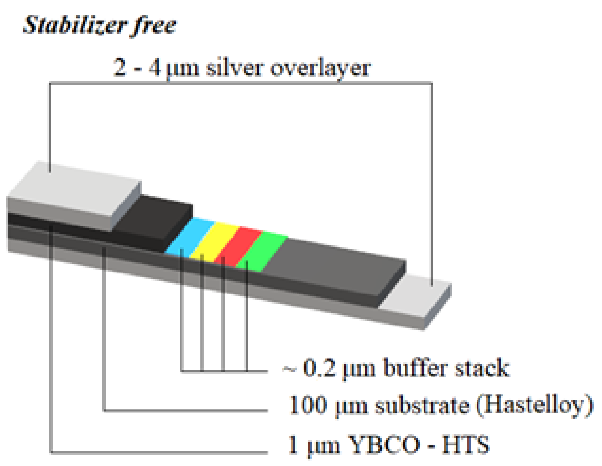
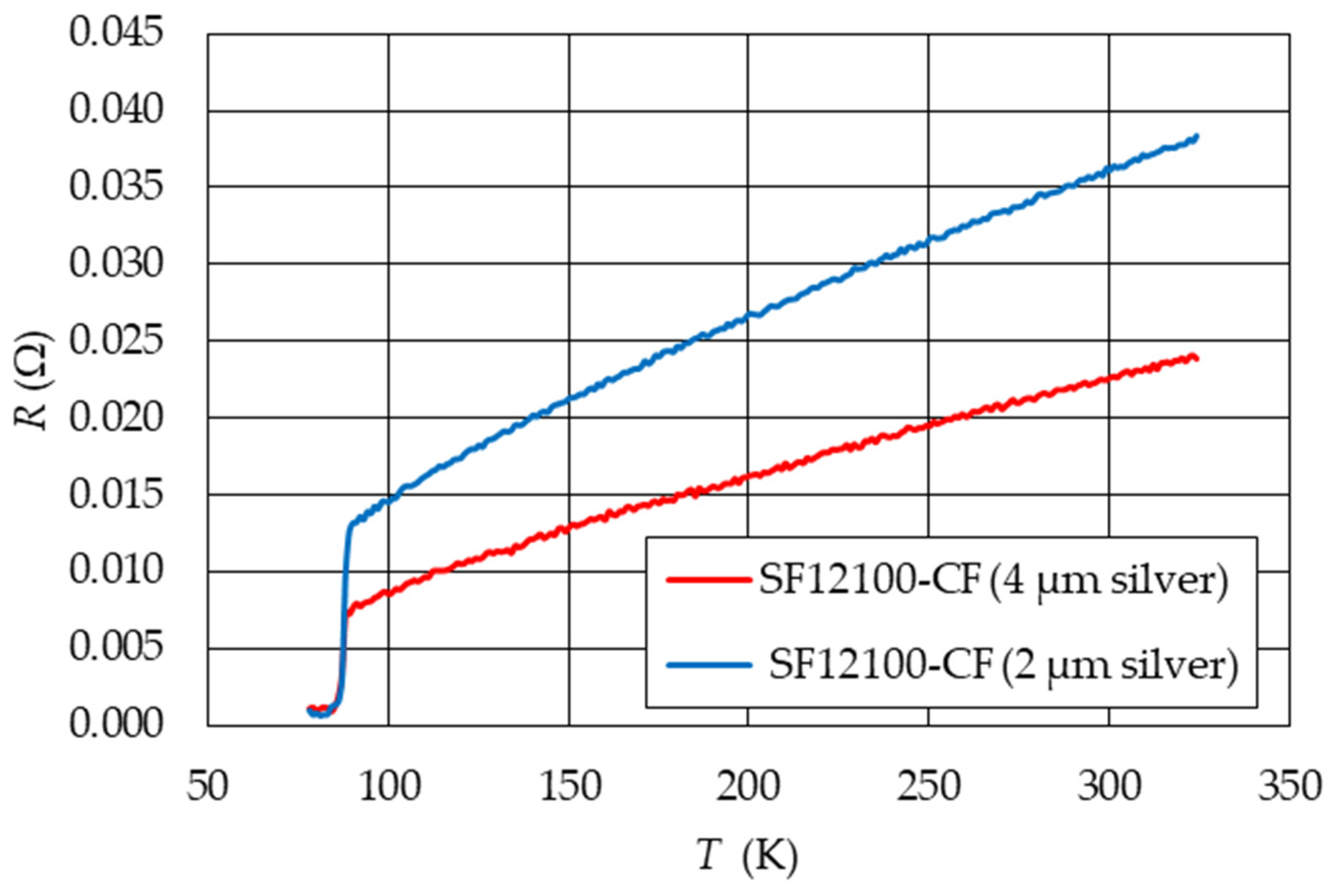
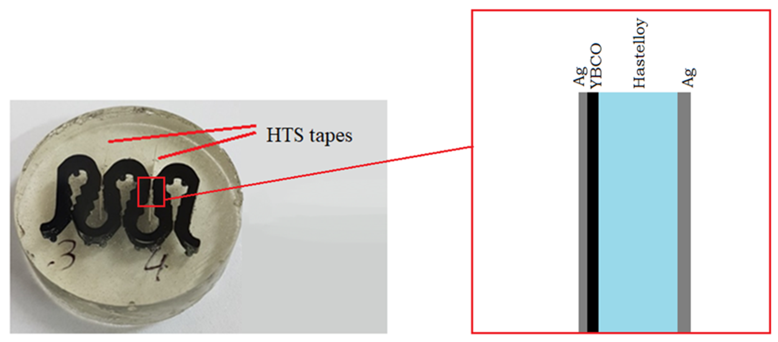
2. Characteristics of the Tested Materials

Measurements were made on tapes SF12100-CF (CF—cable formulation) with YBCO ceramic superconductors dedicated for use in SFCL [33]. The tapes were made in thin-layer technology, in which buffer layers, superconductors, and silver layers were applied successively to a metal substrate—Hastelloy (Figure 1). The parameters of the tapes are shown in Table 1. The structure of the buffer layers of the SF12100-CF tapes is shown in Table 2 [37].
Silver layers act as heat bridges, improving the thermal properties of the HTS tape and its mechanical strength. Due to the different thicknesses of the silver layer, the HTS tapes used for testing have different resistances at temperatures above the critical temperature.
Figure 2 shows the temperature characteristics of the resistance obtained for the tested HTS tapes heated at room temperature in air.
For the HTS tape immersed in liquid nitrogen, the temperature of which in the resistive state increases as a result of the current flow, the heat transfer takes place according to the Leidenfrost effect and depends on the temperature difference between the sample surface and liquid nitrogen and the processes occurring at their contact. This process has four stages: natural convection, nucleate boiling, transition boiling, and film boiling [13,38], as shown in Figure 3.

3. Measuring System, Method, and Scope of Research

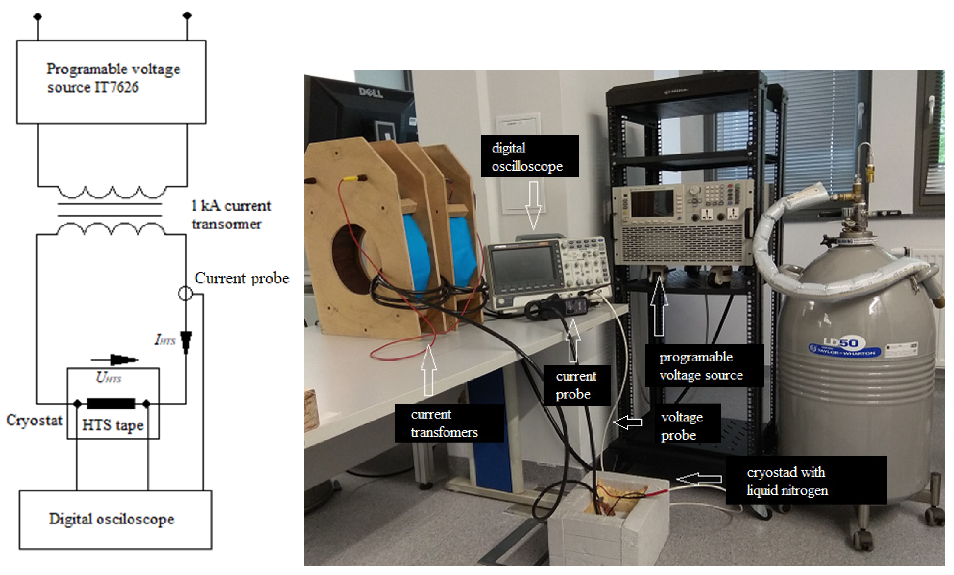
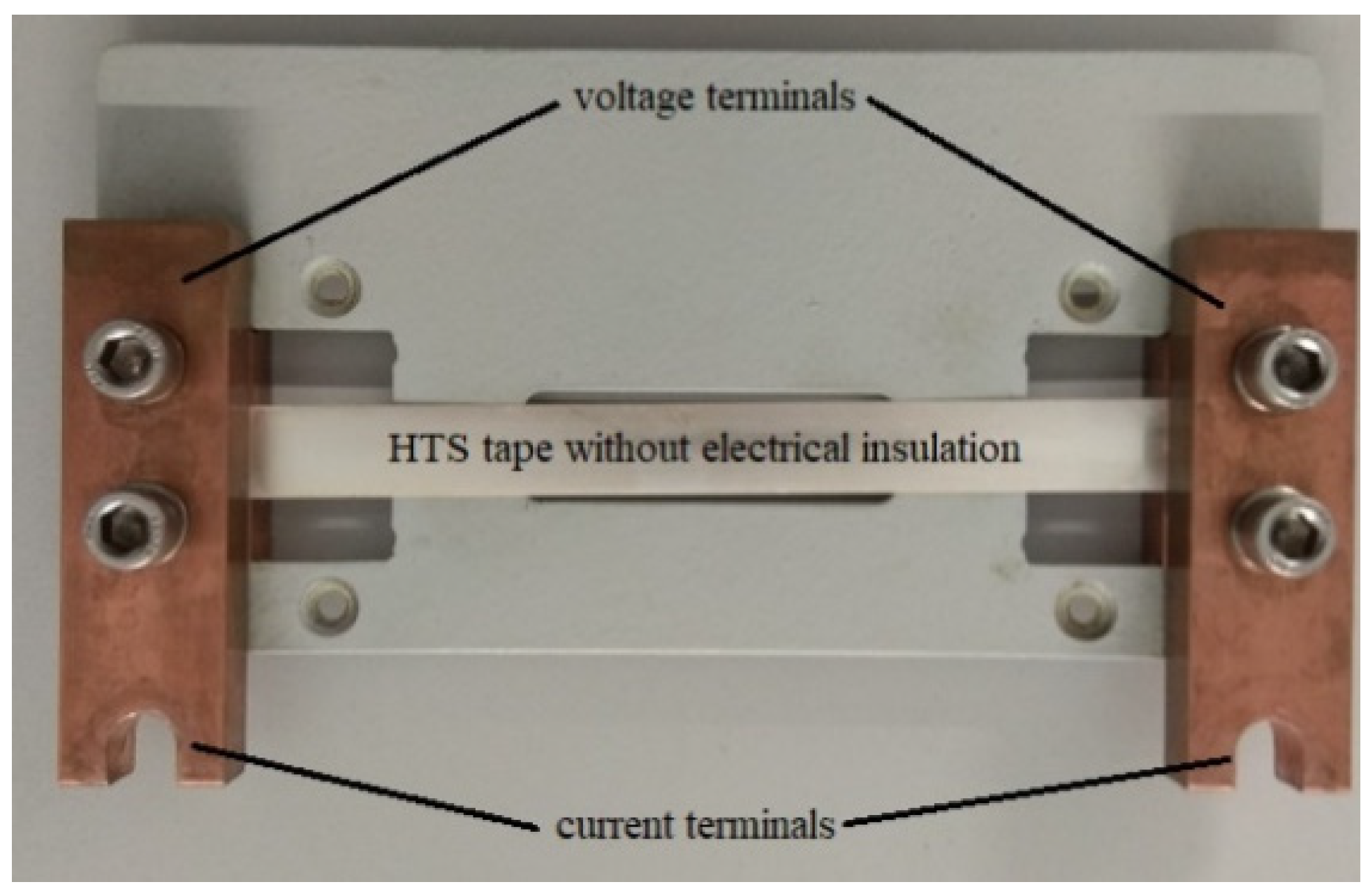
3.1. Measuring System

The measuring system shown in Figure 4 comprises a programmable voltage source IT7626, current transformers, Rigol MSO 5074 digital oscilloscope, and a cryostat with liquid nitrogen. The tape current was measured with the CP 1005 current probe. A programmable voltage source with a power of 3 kVA generates voltage waveforms with adjustable amplitude and frequency, enabling current waveforms. The method of mounting HTS tape samples with a length of 10 cm is shown in Figure 5.

3.2. Methods of Research

The prospective short-circuit current (Ip) is the current that would flow in the considered circuit if the SFCL did not limit it. On the other hand, due to the HTS tape leaving the superconducting state, the expected short-circuit current is limited. The highest possible instantaneous value of the short-circuit current is the surge current (I0max). When limiting the expected short-circuit current, due to the dynamics of the process of transition of the tape to the resistive state, the surge current (I0max) may significantly exceed the value of the critical current (IC). This process takes place in a few milliseconds. During the operation of the SFCL, there is a gradual increase in the voltage on the tape and a decrease in the current value due to the increase in temperature and, thus, the resistance of the tape. As a result of SFCL operation, the current is limited to the value Ilim, and Imin is the amplitude of the current limited at the end of the test pulse; Umax is the maximum voltage on the HTS tape at the end of the test impulse. Figure 6 shows the principle of short-circuit containment by SFCL.

3.2.1. Determination of the Critical Current of HTS Tapes

Critical current (IC) values of HTS tapes provided by manufacturers are determined with direct current forcing [39]. The method of determining the critical current with a sinusoidal excitation with a frequency of 50 Hz is shown in Figure 7.
The test sample was subjected to a test current pulse (I) of 100 ms duration. The critical current (IC) of the tested HTS tape samples was assumed to be the minimum value of the test current amplitude initiating the sample’s exit from the superconducting state. The IC value was determined by gradually increasing the amplitude of the current I in the tested sample. For test currents (I) lower than the critical current (IC), the HTS current amplitude had a constant value, and the voltage on the sample had a negligible value related to the resistance of the junctions (Figure 7a). After the tape exited the superconducting state (IIC), the voltage on the sample increased and the current decreased (Figure 7b).

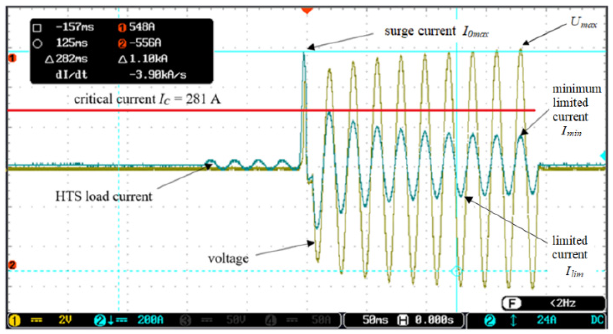
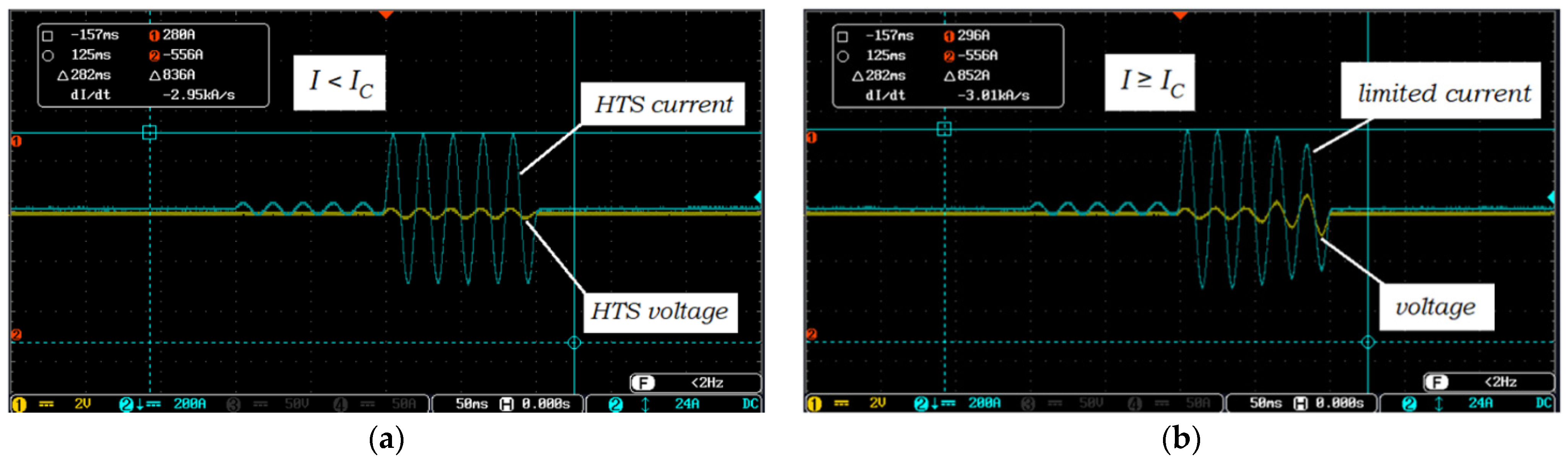
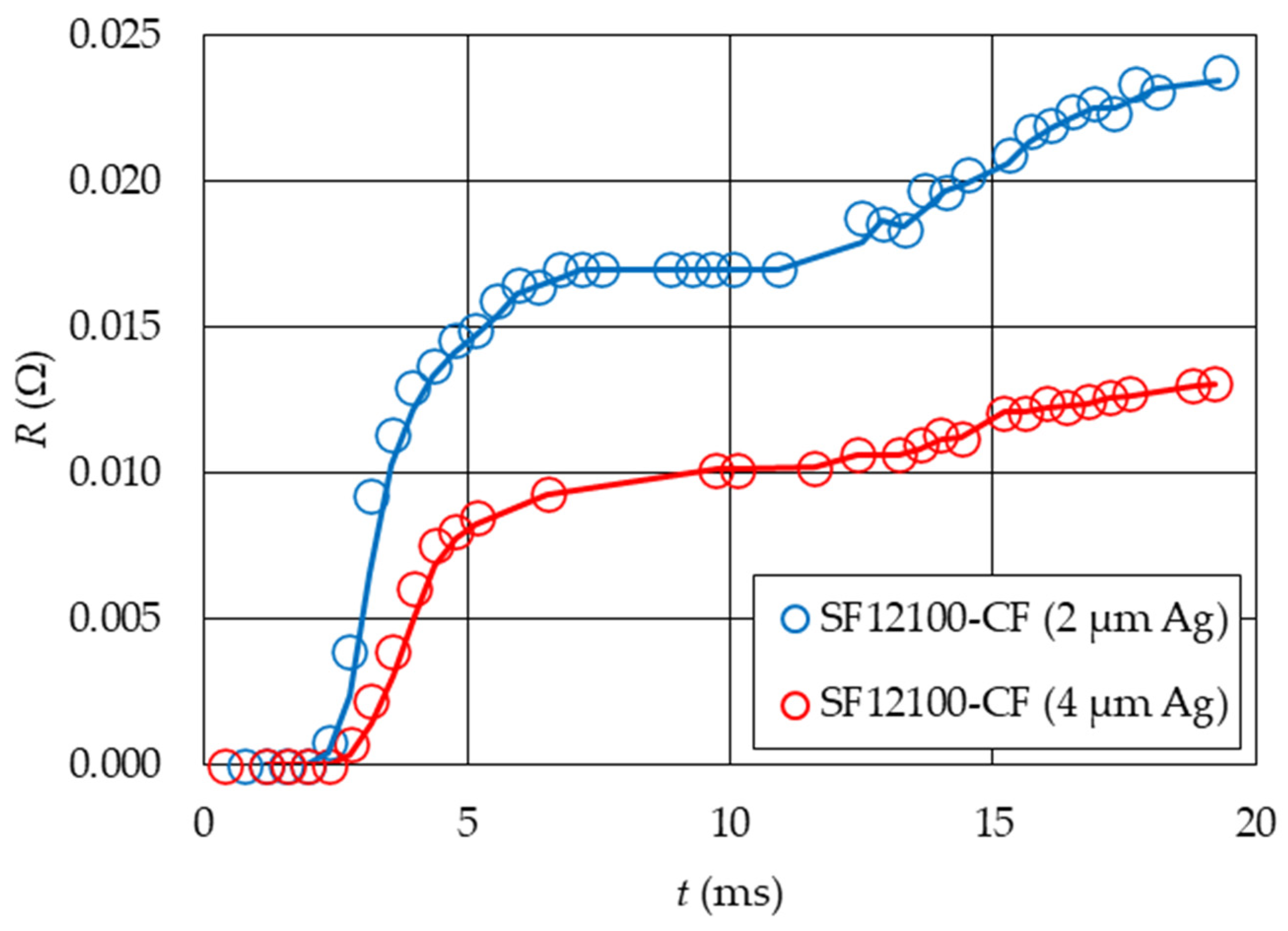
3.2.2. Determination of the Value of Surge and Limited Current and Voltage on the HTS Tape

The HTS tapes were subjected to test current impulses with amplitudes significantly exceeding the critical current value. Due to the transition of the HTS tape from the superconducting state, the expected short-circuit current was limited to the value of Imin.
There was a gradual increase in the voltage on the HTS tape and a decrease in the current value due to the increase in temperature and, thus, the tape resistance.
On the basis of the recorded waveforms, the characteristic values I0max, Imin, Umax, and the energy released in the belt for various values of the test pulse were determined:
E = Δ t n n = 1 k u n · i n
where: E—the amount of energy released on the sample, Δt—impulse duration, u—instantaneous voltage on the tape, i—the instantaneous value of the current, n—number of samples.

3.3. Scope of Research

The tests were carried out for SF12100-CF tapes with silver layers of 4 µm and 2 µm. The HTS tapes were subjected to test current impulses (corresponding to the value of the prospective short-circuit current) with a duration of 0.2 s. The research was performed for 8 values of the prospective short-circuit current in the range from 675 A to 1170 A.
The research included:
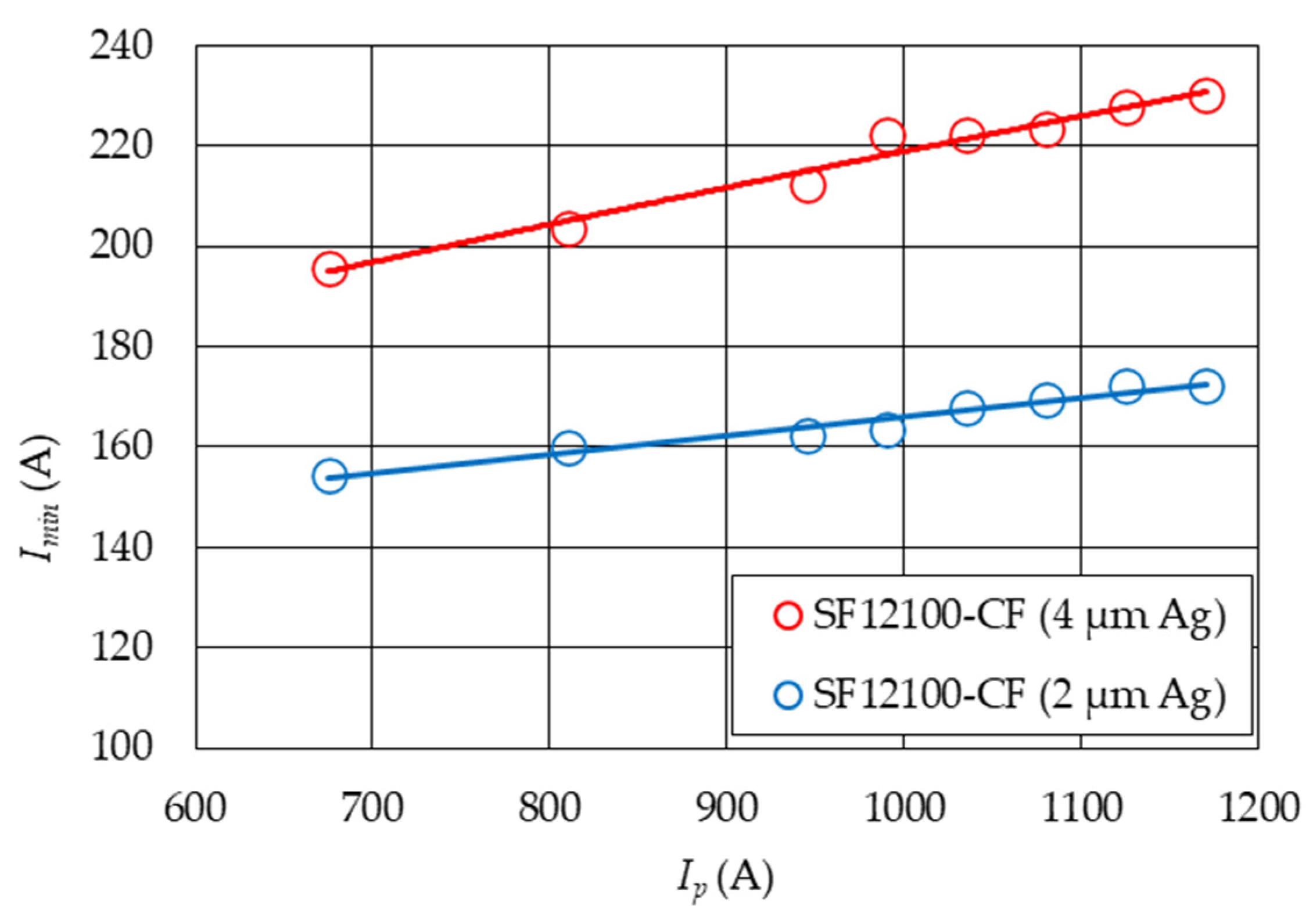
  • Determination of the values characterizing the HTS tapes in the process of limiting the prospective short-circuit current (I0max, Imin) and changes in the critical current (IC) value occurring as a result of multiple transitions of the tapes from the superconducting state. These values are important from the point of view of cooperation between SFCL and system protection;
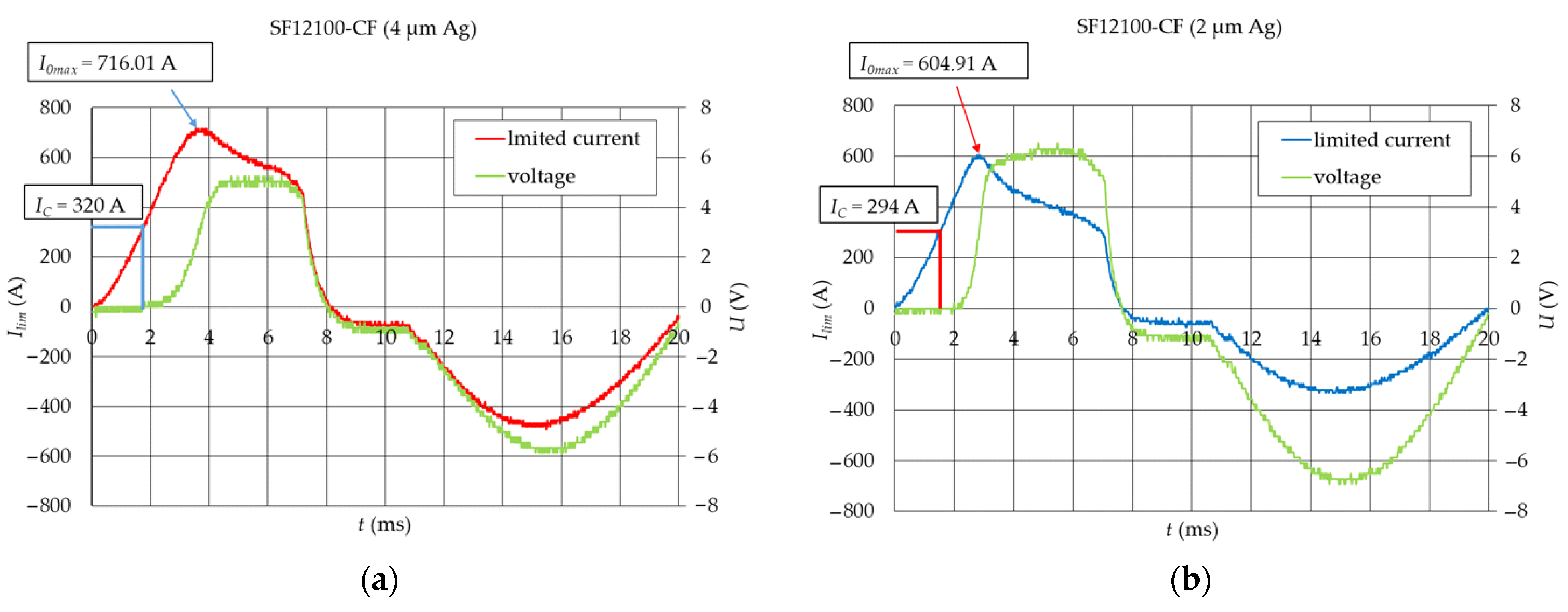
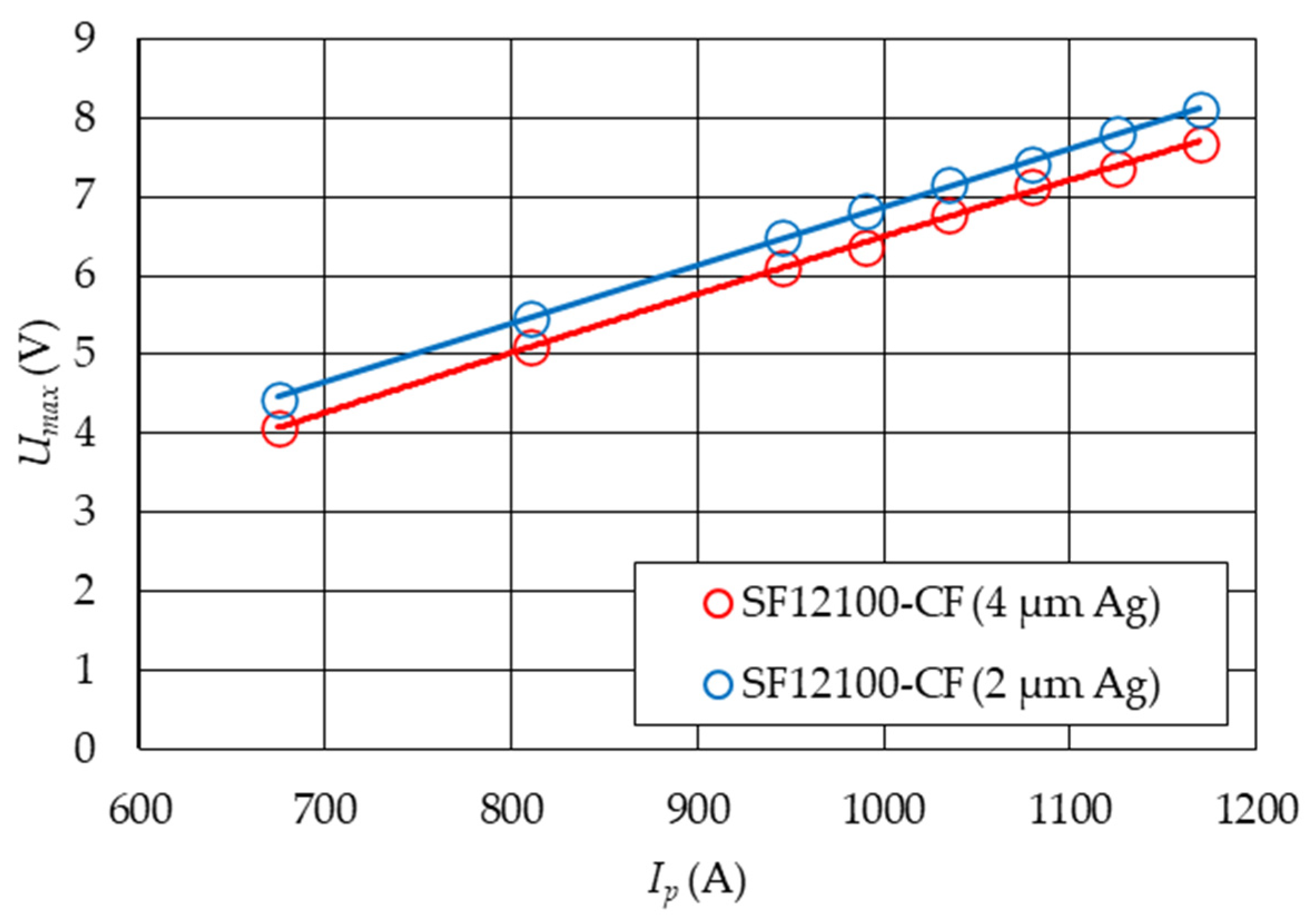
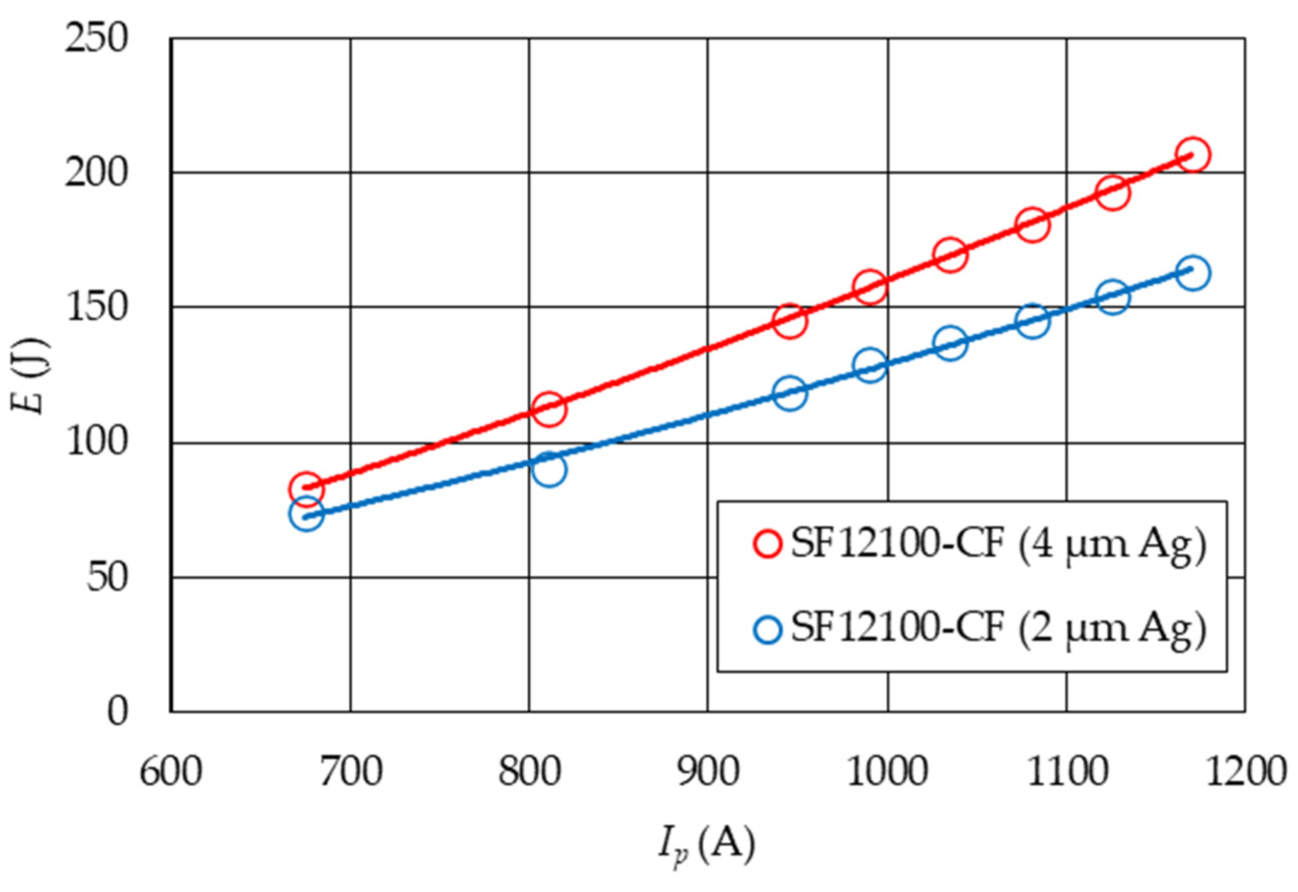
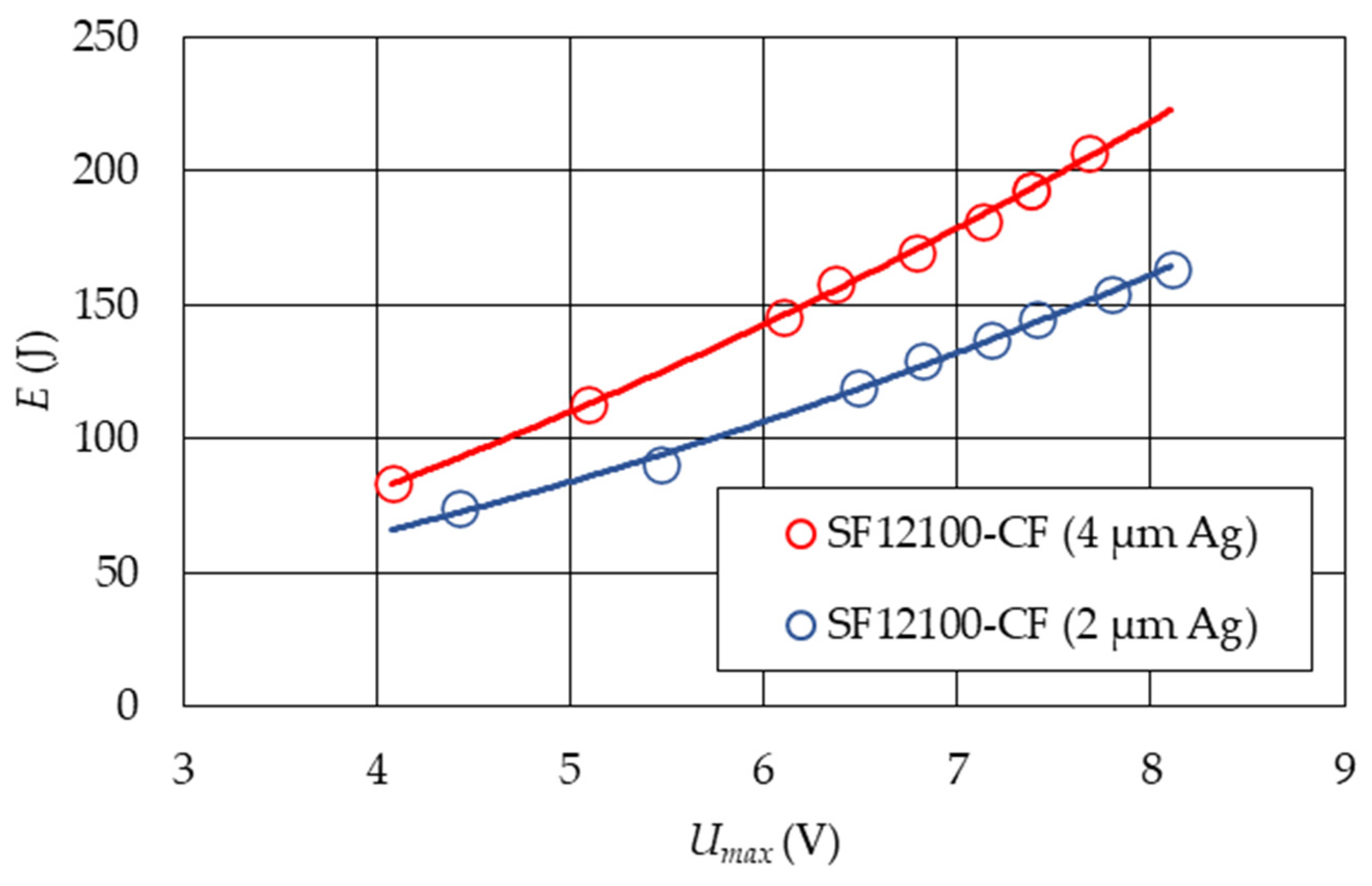
  • Determination of the voltage (Umax) and energy E released in the HTS tapes during the operation of the test current pulse for different values of the prospective short-circuit current;
  • Testing changes in quantities that characterize HTS tapes in conditions of multiple exposures to test currents;
  • Determination of the safe range of voltage drops per unit length for both tapes for which the degradation of HTS tapes does not occur or is small;
  • The above issues are important for determining the required length of the HTS tape in SFCL, operating at a specific rated voltage, so that the voltage drops on the HTS tape do not exceed the permissible values.
Additionally:
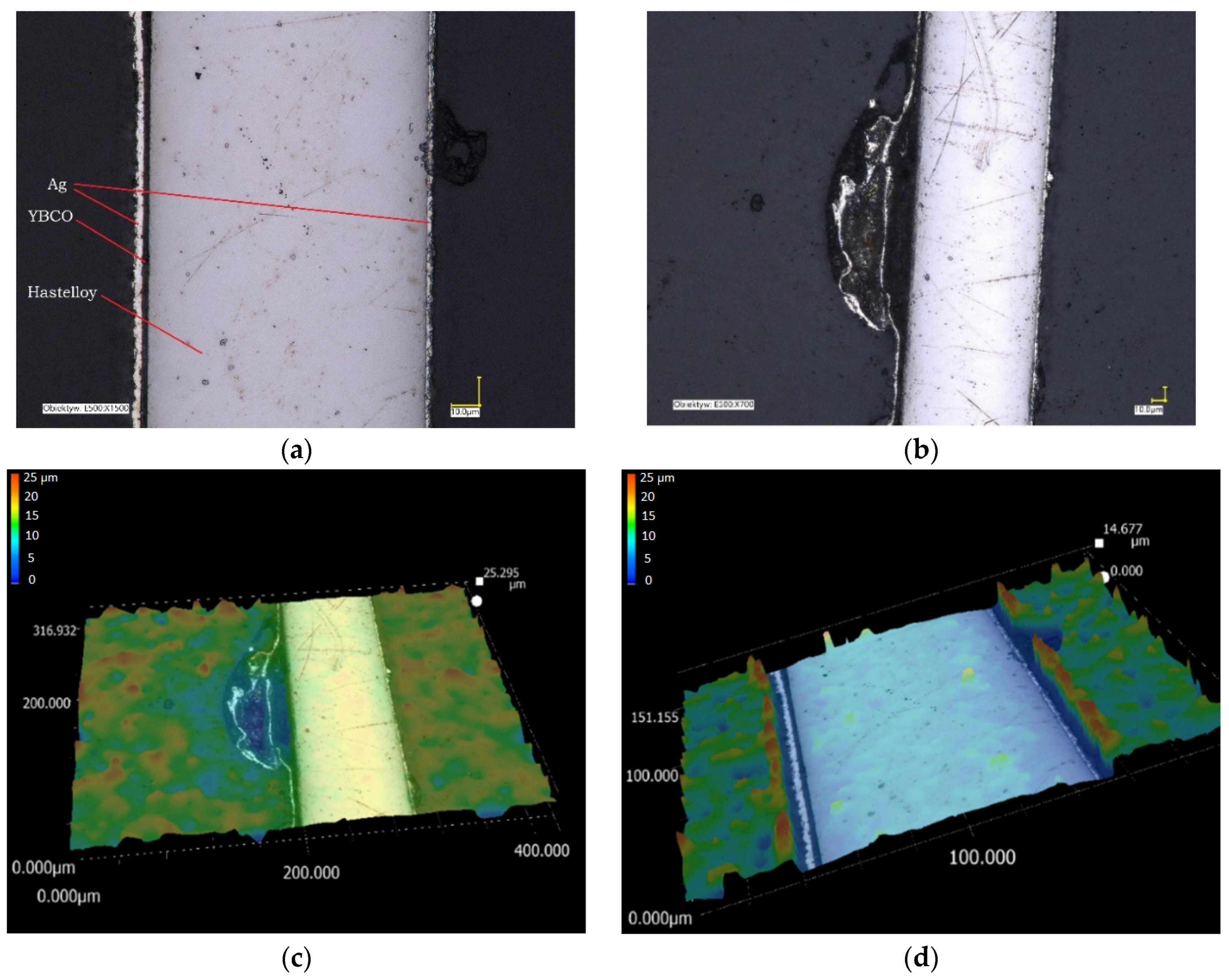
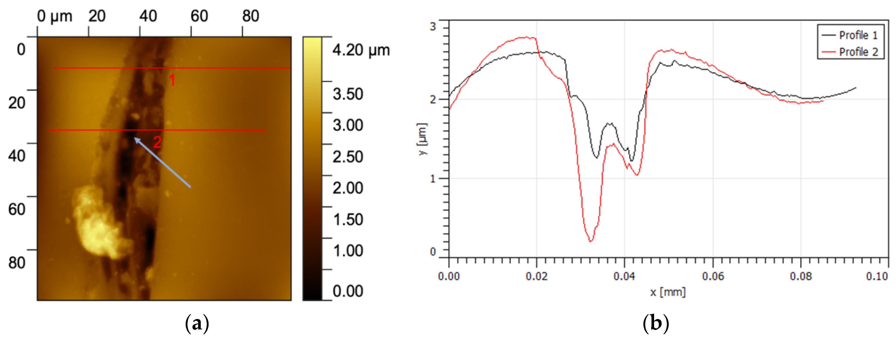
  • Microstructural tests showed changes in the HTS tape due to the current impulses test. The cross-sectional surfaces of the tapes were examined using an atomic force microscope (AFM) and an optical microscope (OM).

4. Experimental Results

As a result of the measurements, the results of I0max, Imin, Umax, and E were obtained and are presented in Table 3.

4.1. Study of Changes in the Value of Surge Currents as a Function of the Prospective Short-Circuit Current

The prospective short-circuit current Ip was limited due to the HTS tape transition from the superconducting state to the value of the surge current I0max. The values of the surge currents for the eight values of the prospective short-circuit current for the tested HTS tapes are shown in Figure 8. The green line indicates the values of the prospective short-circuit current (Ip). With the increase in the value of the prospective short-circuit current, the value of the surge current increased. The surge current reached lower values for the SF12100-CF tape with a 4 μm silver layer (Figure 8).
The surge current (I0max) recorded on the samples reached values higher than the critical current of the tested HTS tape (which is related to the dynamics of the process of the tape transition from the superconducting state), which is shown in Figure 9a,b. The exit of the tape from the superconducting state was indicated by the appearance of a non-zero voltage value on the sample. The HTS tape transitioned to a resistive state, and the resistance of the tape gradually increased as a result of the heating of the sample due to the current flow (Figure 9). The prospective short-circuit current was limited and reached the value of the surge current I0max.
Figure 10 shows changes in the resistance value of the tested HTS tapes during the first 20 ms. The dynamics of current and voltage changes on the sample can be related to the sample cooling conditions in liquid nitrogen according to the Leidenfrost effect [38]. In the initial phase of the HTS tape transition from the superconducting state, the heat exchange between the tape and liquid nitrogen takes place by natural convection, which occurs at small temperature differences between the HTS tape and the cryogenic liquid. After the current reaches the I0max value, the nucleate boiling phase begins. The temperature of the tape increases, but at the same time, a very intensive heat transfer from the HTS tape to nitrogen starts. A decrease in the current value and stabilization of the voltage value on the tape are observed, while the resistance of the tape increases very slightly. Then, in a very short period of time, there is a momentary increase in resistance (transition boiling). For both HTS tapes, the current and voltage values stabilization was observed from about 8 ms, corresponding to reaching the Leidenfrost point. The film boiling process begins with a linear relationship between the heat flow from the tape to liquid nitrogen.

4.2. Study of Changes in the Value of the Minimum Currents Limited as a Function of the Prospective Short-Circuit Current

During the test impulse (0.2 s) duration, the prospective short-circuit current was limited to the value Imin (Figure 11).
The increase in resistance during the current pulse duration for the tested HTS tapes is shown in Figure 12. In the resistive state, the silver layer mainly takes over the current conduction [40]. The degree of limiting is determined by the resistance of this layer, which justifies the higher value of the current limit for a tape with a thickness of 4 µm. The change in the resistance value over time and the value of the limited short-circuit current of HTS tapes depends on the temperature of the tape and the intensity of heat transfer from the tape to liquid nitrogen (Figure 3).

4.3. Examination of Changes in Voltage Values and Energy Dissipated on HTS Tapes as a Function of the Prospective Short-Circuit Current

At the end of the test impulse, the maximum voltage value (Umax) is set on the sample. During the duration of the test impulse, energy (E) is released on the tape. The maximum values of voltage amplitudes (Umax) on HTS tapes as a function of the prospective short-circuit current (Ip) are shown in Figure 13. Slightly higher voltage values were recorded for the SF12100-CF tape with a 2 μm silver layer.
The values of energy (E) dissipated on HTS tapes as a function of the prospective short-circuit current (Ip) are presented in Figure 14. The energy (E) values released on the samples of both HTS tapes are higher for the tape with a 4 µm silver layer.
Figure 15 shows the dependence of the energy released in the belt as a function of the voltage set on the HTS tape (Umax). As the voltage on the samples increases, the amount of energy released increases. Due to the higher energy values and higher values of surge currents for the HTS tape with a 4 µm silver layer, worse working conditions of this tape in the resistive state can be expected. The tape heats up more as a result of the test current impulses, which may result in a change in the tape parameters.

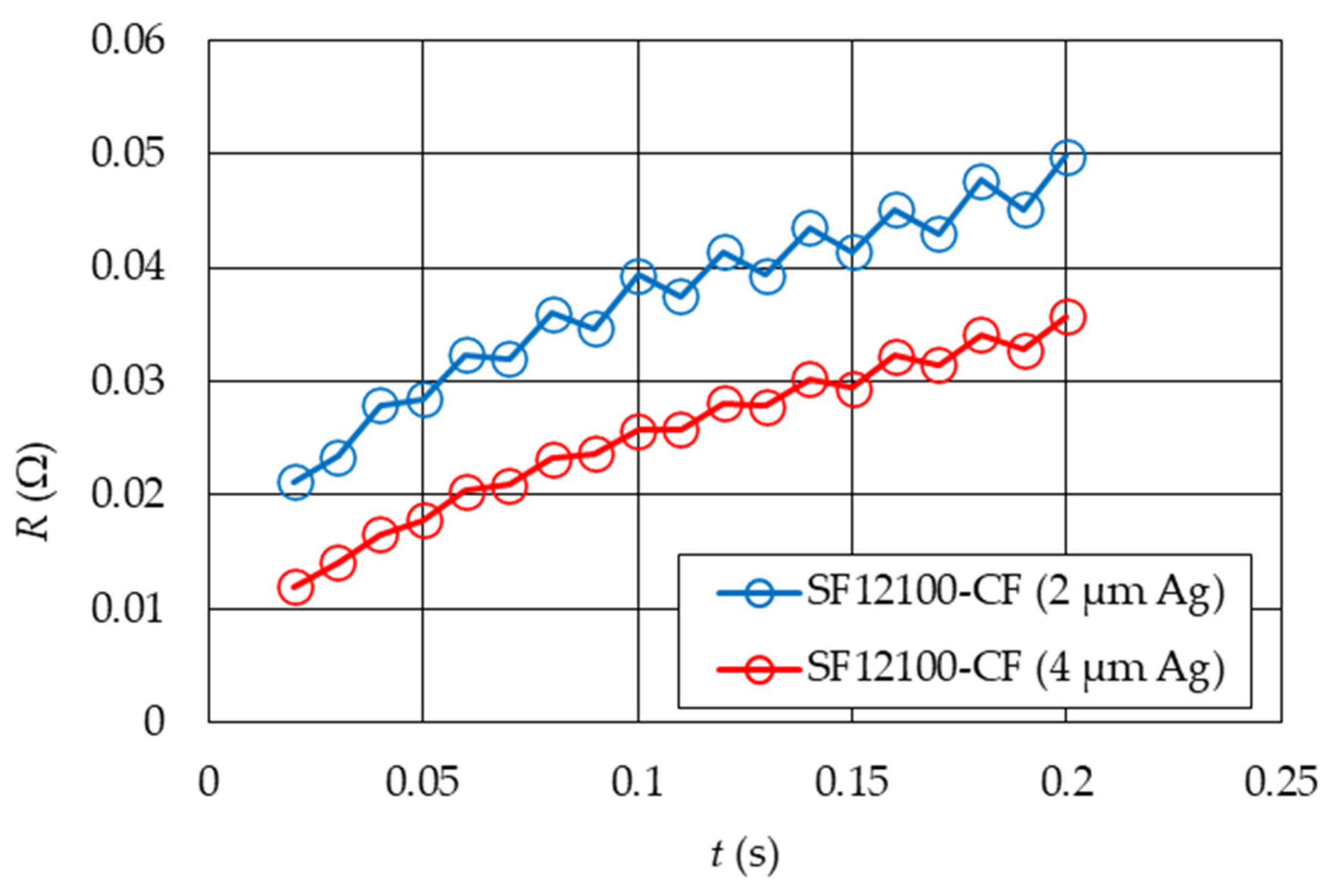
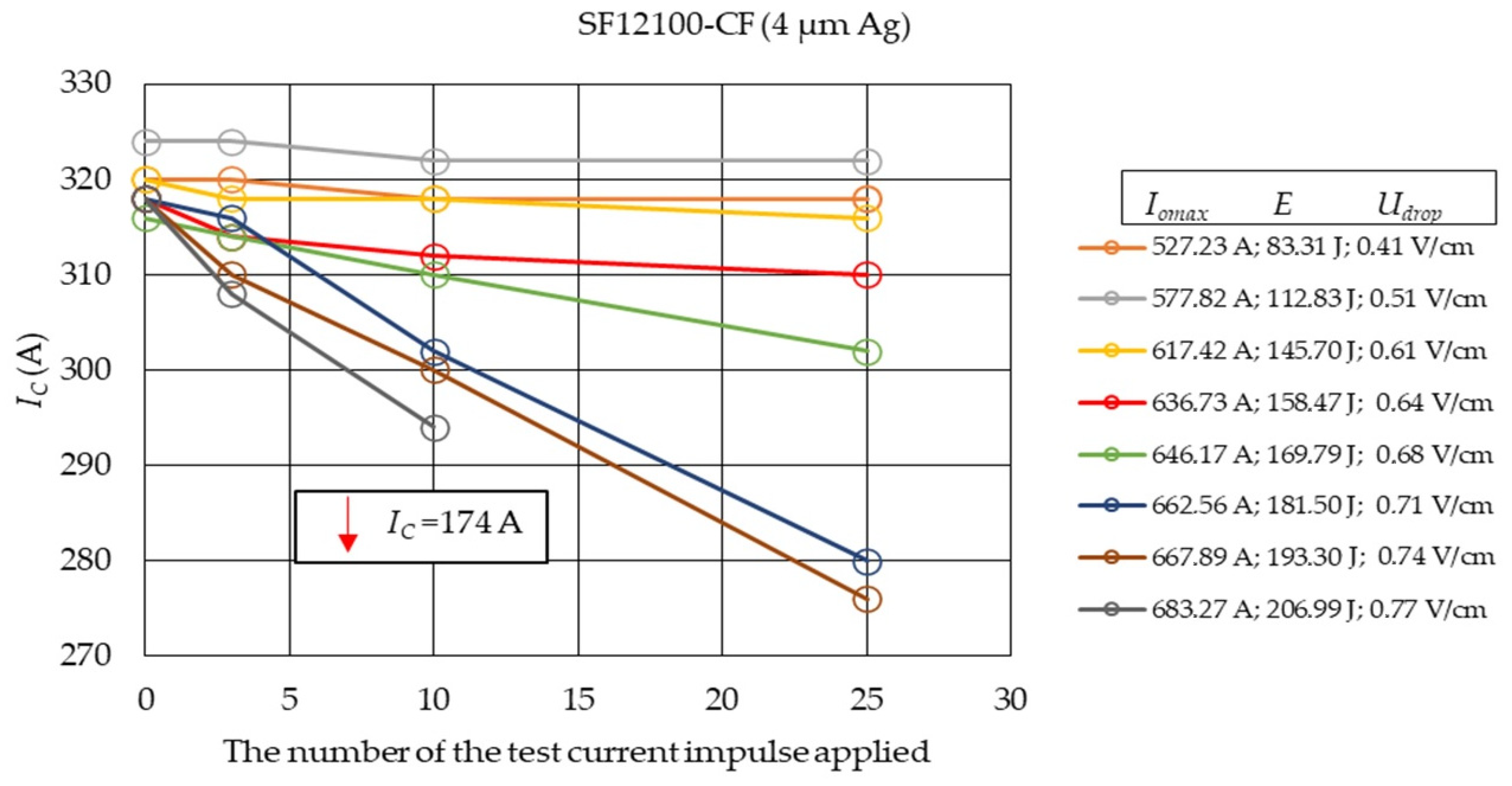
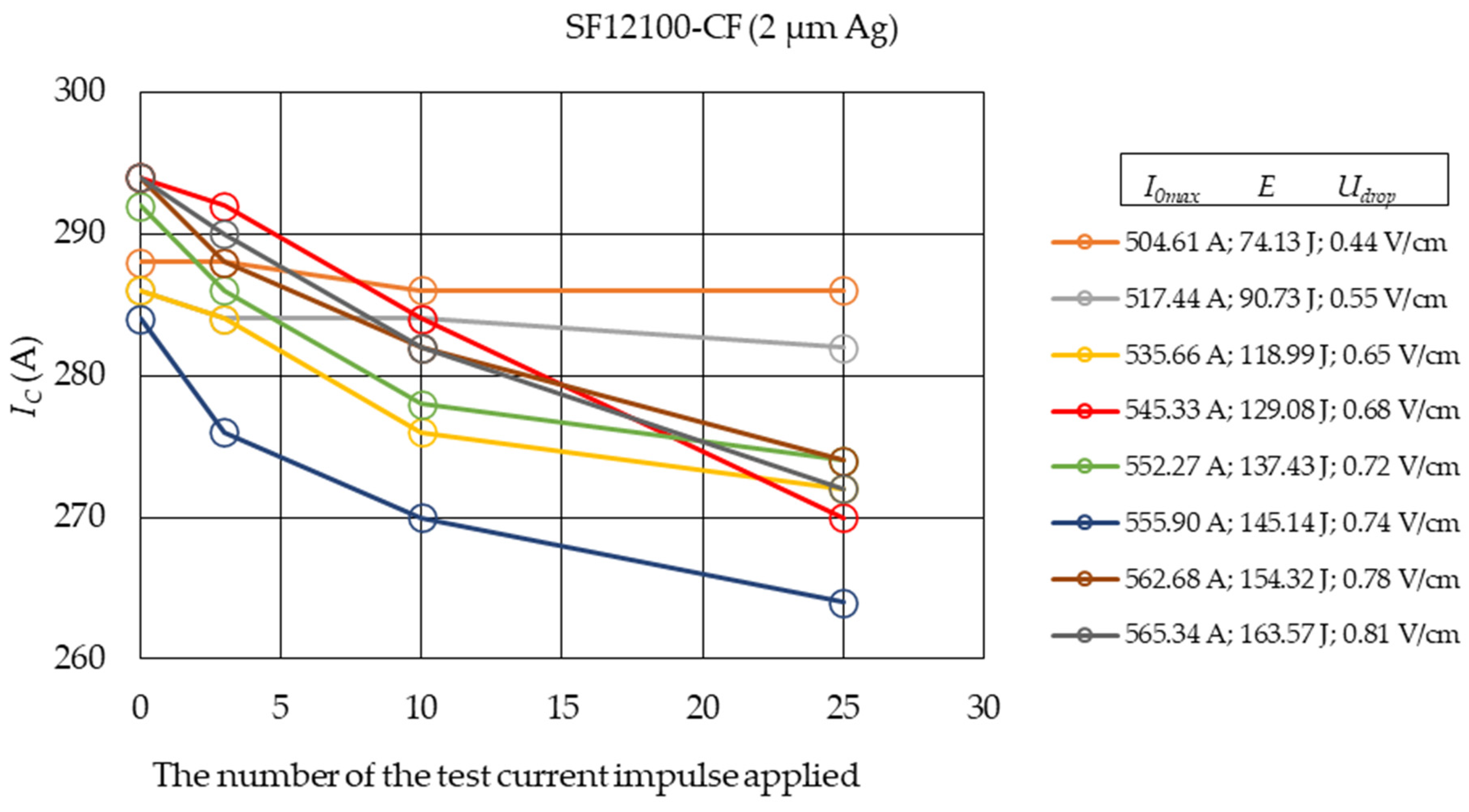
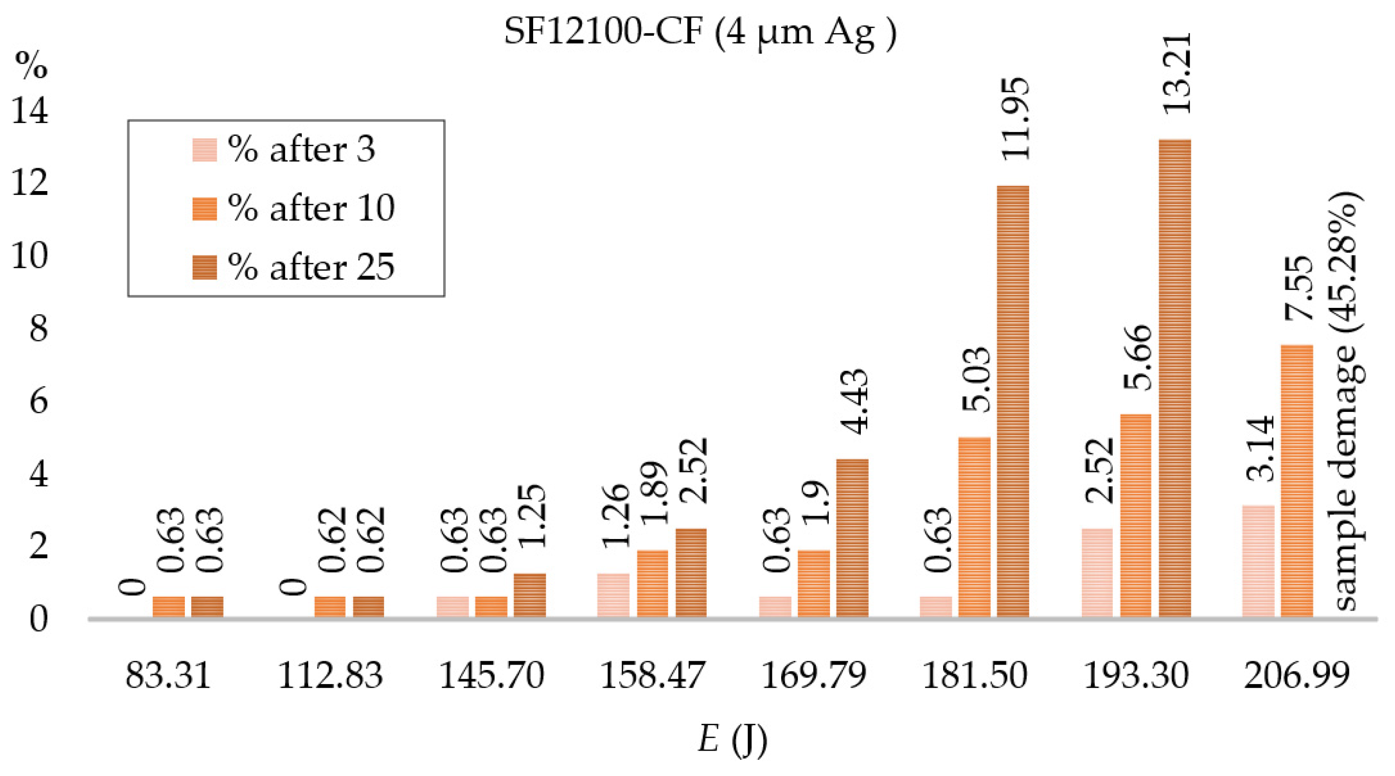
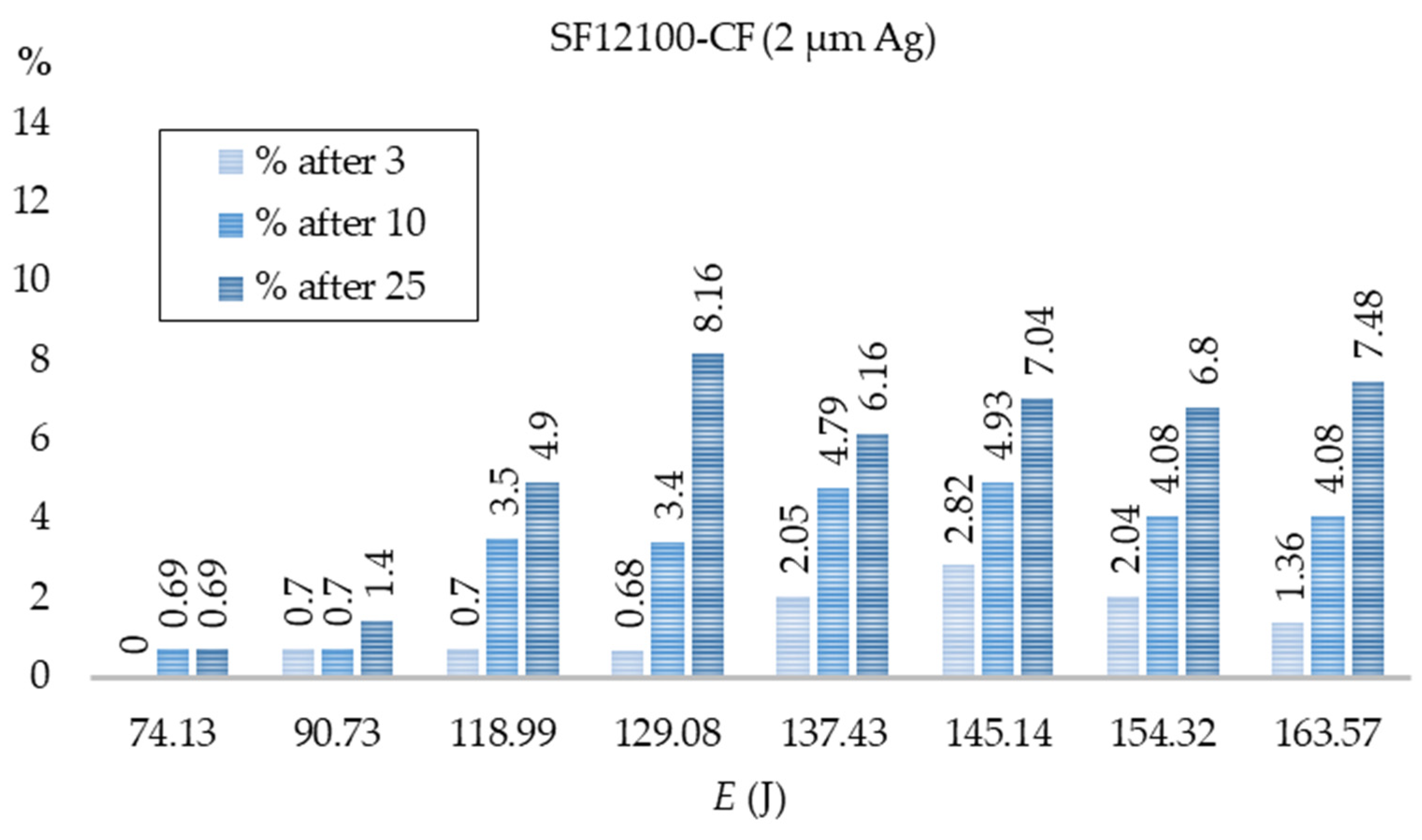
4.4. Examination of Changes in the Critical Current of HTS 2G Tapes as a Result of the Repeated Impact of Test Current Impulses

The tested HTS tapes samples were exited of the superconducting state by test current impulses with values significantly exceeding the value of the critical current (IC) of the HTS tapes for 8 different values of the prospective short-circuit current. Between the test current impulses, pauses allowed the system to return to thermal equilibrium and the state of superconductivity. The value of the critical current (IC) of the tested samples was measured for an unused sample (IC0) and then after 3 applications of the test current impulses and after applications 10 and 25. According to the manufacturer of HTS tapes, the values of the critical current (IC0) of new samples of HTS tapes may slightly differ, as was described in [33].
The results of critical current measurements for HTS SF12100-CF tape samples with 4 µm and 2 µm silver as a function of the number of test current impulses activations for 3, 10, and 25 transitions from the superconducting state are shown in Figure 16 and Figure 17. With the increase in the number of transitions from the superconducting state in the tested samples, the value of the critical current decreased. The rate of degradation of the critical current of HTS tapes depends on the value of the test current. For one of the samples of HTS tape (with an energy of 206.99 J and a voltage drop of 0.77 V/cm), after 25 applications of the test current impulse, the IC value dropped to 174 A.
During the tests of changes in the value of the critical current, the voltage drop values were also recorded, and the value of the energy released in the HTS tape during the test pulse was determined. The results are shown in Figure 18 and Figure 19. For the tested HTS tapes, a decrease in the value of the critical current was observed, increasing with the number of exits of the tapes from the superconducting state.
For the HTS tape with a 4 µm silver layer, slight decreases in the value of the critical current were observed for the test current pulses, for which the energy released on the sample did not exceed 158.47 J (IC drop below 3% for 3, 10, and 25 activations of the test current pulses). For the HTS tape with a 2 µm silver layer, similar IC changes were observed at energies of 90.73 J. For higher energy values, the degradation process was more noticeable. After 10 leads, the difference in the decrease in the critical current depending on the thickness of the silver layer was clearly marked. At the highest energies, after 10 leads, the 4 µm silver tape had a 7.55% decrease in IC and 4.08% for the 2 µm silver tape, and the 4 µm silver tape showed a 45.28% decrease in IC after 25 leads (it should be assumed that the tape has been damaged), while the 2 µm silver tape only decreased by 7.48%. For low values of prospective current (energy dissipated in the HTS tape), changes in the value of the critical current are negligible. This parameter degrades faster with the number of current test operations for higher energy values, which means the progressing process of thermal aging of the HTS tapes. The process is much more intensive for the HTS tape with a 4 µm silver layer due to the lower resistance value of the silver layer.
Based on the test results, it is possible to determine the permissible value of voltage drops for HTS tapes, at which IC degradation does not occur or occurs only slowly. Paper [41] presents a numerical model of the HTS tape SF12100, based on which the permissible value of voltage drops for a current pulse of 0.2 s duration is 0.47 V/cm. The permissible value of voltage drops is an important design parameter that determines, among other things, the minimum length of the tape used in the SFCL while ensuring the safe operation of the device. In the paper [42], from the point of view of design assumptions, the permissible value of the voltage drop was 1 V/cm.
The HTS tape with a silver layer of 4 µm thickness degrades very quickly above a certain energy value; therefore, a safe voltage drop range of 0.55 V/cm can be assumed, at which the drop in the critical current value does not exceed 3%.

4.5. Testing the Cross-Sectional Area of HTS Tapes

The Nanosurf Flex Axiom, atomic force microscope was used to assess the cross-sectional morphology of the sample of HTS tapes. Measurements were made in a non-contact mode using the NCLR probe by NanoWorld and the VHX-7100 optical microscope by Keyence.
In order to conduct a microscopic examination, samples of the tested tapes were embedded in epoxy resin and then polished (Figure 20).
The results obtained with the use of an optical microscope indicate the presence of local distortions in the form of bubbles in the superconducting layer and on the surface of the tape from the superconductor side. Figure 21b shows one of several defects in the cross-section of a superconducting tape embedded in epoxy resin. The possibility of distortions during the sample preparation process should be ruled out as no such distortions were observed in the control samples (Figure 21a).
For a more detailed analysis of defects in the samples subjected to the surge currents, measurements were carried out using the AFM technique, which is shown in Figure 22. In the topography image (Figure 22a), the profiles are marked with red lines, the curves of which are shown in Figure 22b. Profile lines guided through two areas within the defect. Due to different thermal expansion coefficients, the superconducting layer is below the Hastelloy, silver, and resin layers in both cross-sections. However, it is noteworthy that there are specific depressions in a part of the superconducting layer (marked with a blue arrow), which may be material losses in the superconducting layer.
The microscopic examinations showed the existence of bubble-like changes formed on the HTS tapes due to the impact of currents in the layers of silver and superconductor. They were observed in all samples subjected to the surge current. Control samples showed no such changes. At the same time, no differences were found at the superconductor–Hastelloy boundary, and no changes in the silver layer and the silver–Hastelloy boundary on the other side of the tape. This may indicate that the reasons for the changes are processes taking place in the superconductor, which require further research and analysis.
The bubble-type microdamage may be areas that initiate damage to the THS tape, affecting the change in the value of the critical current of the tape and the need for a faster replacement of superconducting elements in the SFCL or the entire device. Determining the degradation mechanisms of HTS tapes is essential from the point of view of the correct operation and lifetime of the SFCL and requires further research.

5. Conclusions

  • In HTS tapes subjected to multiple test current pulses (corresponding to the values of the prospective short-circuit current), the value of the critical current decreases depending on the number of transitions from the superconducting state.
  • The value of the critical current of the HTS tapes decreases with the increase in the value of the test impulse.
  • Measurements of the energy released in the sample during the operation of the test impulse allow us to determine the permissible range of energy and voltage drops that practically do not change the value of the critical current or do not exceed the permissible values from the point of view of cooperation between the SFCL and the system protection.
  • HTS tape with a silver layer of 4 µm thickness degrades very quickly above a certain energy value; therefore, a safe voltage drop range of 0.55 V/cm can be assumed, at which the drop in the critical current value does not exceed 3%.
  • Decrease in the value of the critical current of the HTS tape due to multiple occurrences of a short circuit in the SFCL system should be considered at the design stage. It should be controlled during the operation of the SFCL.
  • Morphological studies reveal that HTS tapes subjected to test current impulses (corresponding to the values of the prospective short-circuit current), causing their exit from the superconducting state, and show microdamage occurring in the superconducting layer and the boundary layer between the superconductor and silver in the form of bubbles, which may cause degradation.
  • The observed microstructural changes in HTS 2G tapes due to the effect of test currents on the parameters of HTS tapes require further research and analysis. Future research will include an extension of microstructural studies and statistical studies.

Author Contributions

Conceptualization, S.H. and A.K.; methodology, S.H., A.K., and M.M.; investigation, S.H. and J.R.; writing—original draft preparation, S.H., K.S., and M.M.; writing—review and editing, A.K. and P.S.; visualization, S.H. and M.M.; supervision, A.K. and P.S. All authors have read and agreed to the published version of the manuscript.

Funding

This research received no external funding.

Institutional Review Board Statement

Not applicable.

Informed Consent Statement

Not applicable.

Data Availability Statement

Not applicable.

Acknowledgments

The authors would like to thank Miroslaw Roman Dudek for the discussion and substantive support. The authors thank Kayen for making the measurements possible.

Conflicts of Interest

The authors declare no conflict of interest.

References

  1. Fault Current Limiters, Raport on the CIGRE WG A3.10. In Proceedings of the CIGRE WG 13.10. Available online: https://www.ewh.ieee.org/soc/pes/switchgear/presentations/tp_files/2003-2_Lunch_1_A3-10.pdf (accessed on 27 March 2023).
  2. Sung, B.C.; Park, D.K.; Park, J.W.; Ko, T.K. Study on a series resistive SFCL to improve power system tranient stability: Modeling, simulation, and experimental verification. IEEE Trans. Ind. Electron. 2009, 26, 2412–2419. [Google Scholar] [CrossRef]
  3. Rao, V.V.; Kar, S. Superconducting Fault Current Limiters—A Review. Indian J. Cryog. 2011, 36, 14–25. [Google Scholar]
  4. Nagarathna, M.C.; Murthy, H.V.; Shashikumar, R. A Review on Super Conducting Fault Current Limiter (SFCL) in Power System. Int. J. Eng. Res. Gen. Sci. 2015, 3, 485–489. [Google Scholar]
  5. Gupta, V.; Trivedi, U.; Buch, N.J. Solid State Electronic Fault Current Limiter to Limit the Fault Current in Power System. Physics 2010. [Google Scholar]
  6. Nelson, A.; Masur, L.; Moriconi, F.; De La Rosa, F.; Kirsten, D. Saturated-Core Current Limiter Field Experience at a Distribution Substation. In Proceedings of the 21st International Conference on Electricity Distribution, Frankfurt, Germany, 6–9 June 2011. [Google Scholar]
  7. Yadav, S.; Bharati, K.; Tewari, V. Sperconducting Fault Current Limiter—A Review. Int. J. Appl. Eng. Res. 2019, 14, 2. [Google Scholar]
  8. Ganev, G.I.; Hinov, K.; Karadzhov, N. Fault current limiters-Principiales and application. Siela 2012, 2012, 54–56. [Google Scholar]
  9. Alam, M.S.; Abido, M.A.Y.; El-Amin, I. Fault Current Limiters in Power Systems: A Comprehensive Review. Energies 2018, 11, 1025. [Google Scholar] [CrossRef]
  10. Yang, B.; Kang, J.; Lee, S.; Choi, C.; Moon, Y. Qualification test of a 80 kV 500 MW HTS DC cable for applying into real grid. IEEE Trans. Appl. Supercond. 2015, 25, 5402705. [Google Scholar] [CrossRef]
  11. Lee, S.J.; Yang, H.S. Recent Progresand Design of Three-Phase Coaxial HTS Power Cable in Korea. IEEE Trans. Appl. Supercond. 2019, 29, 1–5. [Google Scholar]
  12. Marian, A.; Hole, S.; Lallouet, N.; Marzahn, E. Development of Hightemperature Superconductivity Transformers for Railway Applications. IEEE Trans. Appl. Supercond. 2003, 13, 2325–2330. [Google Scholar]
  13. Yazdani-Asrami, M.; Sadeghi, A.; Seyyedbarzegar, S.; Song, W. Role of Insulation Materials and Cryogenic Coolants on Fault Performance of MW-Scale Fault-Tolerant Current-Limiting Superconducting Transformers. IEEE Trans. Appl. Supercond. 2023, 33, 1–15. [Google Scholar] [CrossRef]
  14. Schlosser, R.; Schmidt, H.; Leghissa, M.; Meinert, M.; Bruzek, C.E. Development of high temperature superconducting transformers for railway applications. IEEE Electr. Insul. Mag. 2020, 36, 30–40. [Google Scholar] [CrossRef]
  15. Song, W.; Jiang, Z.; Staines, M.; Badcock, R.A.; Zhang, J. Design of a single-phase 6.5 MVA/25 kV Superconducting traction transformer for Chinese Fuxing high-speed train. Int. J. Elect. Power Energy Syst. 2020, 119, 105956. [Google Scholar] [CrossRef]
  16. Haran, K.S.; Kalsi, S.; Arndt, T.; Karmaker, H.; Badcock, R.; Buckley, B.; Haugan, T.; Izumi, M.; Loder, D.; Bray, J.W.; et al. High power density superconducting rotating machines—Development status and technology roadmap. Supercond. Sci. Technol. 2017, 30, 123002. [Google Scholar] [CrossRef]
  17. Song, X.; Buhrer, C.; Brutsaert, P.; Krause, J.; Ammar, A.; Wiezoreck, J.; Hansen, J.; Rebsdorf, A.V.; Dhalle, M.; Bergen, A.; et al. Designing and basic experimental validation of the world’s first MW-class direct-drive superconducting wind turbine generator. IEEE Trans. Energy Convers. 2019, 34, 2218–2225. [Google Scholar] [CrossRef]
  18. Bock, J.; Bludau, M.; Dommerque, R.; Hobl, A.; Kraemer, S.; Rikel, M.O.; Elschner, S. HTS Fault Current Limiters—First Commercial Devices for Distribution Level Grid in Europe. IEEE Trans. Appl. Supercond. 2011, 21, 1202–1205. [Google Scholar] [CrossRef]
  19. Lee, S.; Yoon, J.; Yang, B.; Moon, Y.; Lee, B. Analisis model development and specification proposal of 154 kV SFCL for the application to a live grid in South Korea. Phys. C Supercond. Appl. 2014, 504, 148–152. [Google Scholar] [CrossRef]
  20. Doukas, D.I.; Blatsi, Z.D.; Milioudis, A.N.; Labridis, D.P.; Harnefors, L. Damping of electromagnetic transients in a superconducting VSC transmission system. In Proceedings of the 2015 IEEE Eindhoven PowerTech, Eindhoven, The Netherlands, 29 June–2 July 2015; pp. 1–6. [Google Scholar]
  21. Noe, M.; Steurer, M. High-temperature superconductor fault current limiters: Concepts, applications, and development statuts. Supercond. Sci. Technol. 2007, 20, R15. [Google Scholar] [CrossRef]
  22. Elshiekh, M.E.; Mansour, D.-E.A.; Azmy, A.M. Improving Fault Ride-Through Capability of DFIG-Based Wind Turbine Using Superconducting Fault Current Limiter. IEEE Trans. Appl. Supercond. 2013, 23, 5601204. [Google Scholar] [CrossRef]
  23. Zou, Z.C.; Chen, X.Y.; Li, C.S.; Xiao, X.Y.; Zhang, Y. Conceptual Design and Evaluation of a Resistive-Type SFCL for Efficient Fault Ride Through in a DFIG. IEEE Trans. Appl. Supercond. 2016, 26, 1–9. [Google Scholar] [CrossRef]
  24. Chen, L.; Li, G.; Chen, H.; Ding, M.; Zhang, X.; Li, Y.; Xu, Y.; Ren, L.; Tang, Y. Investigation of a Modified Flux-Coupling-Type SFCL for Low-Voltage Ride-Through Fulfillment of a Virtual Synchronous Generator. IEEE Trans. Appl. Supercond. 2020, 30, 5601006. [Google Scholar] [CrossRef]
  25. Lee, H.Y.; Asif, M.; Park, K.H.; Lee, B.W. Feasible Application Study of Several Types of Superconducting Fault Current Limiters in HVDC Grids. IEEE Trans. Appl. Supercond. 2018, 28, 5601205. [Google Scholar] [CrossRef]
  26. Lee, H.-Y.; Asif, M.; Park, K.-H.; Lee, B.-W. Assessment of appropriate SFCL type considering DC fault interruption in full bridge modular multilevel converter HVDC system. Phys. C Supercond. Appl. 2019, 563, 1–6. [Google Scholar] [CrossRef]
  27. Xi, J.; Pei, X.; Song, W.; Niu, L.; Liu, Y.; Zeng, X. Integration of superconducting fault current limiter with solid-state DC circuit breaker. Int. J. Electr. Power Energy Syst. 2023, 145, 108630. [Google Scholar] [CrossRef]
  28. Reddy, S.R.P.; Kar, S.; Rajashekara, K. Resistive SFCL Integrated Ultra-Fast DC Hybrid Circuit Breaker for Subsea HVDC Transmission Systems. In Proceedings of the 2021 IEEE Industry Applications Society Annual Meeting (IAS), Vancouver, BC, Canada, 10–14 October 2021; pp. 1–6. [Google Scholar]
  29. Moon, W.-S.; Won, J.-N.; Huh, J.-S.; Kim, J.-C. A Study on the Application of a Superconducting Fault Current Limiter for Energy Storage Protection in a Power Distribution System. IEEE Trans. Appl. Supercond. 2013, 23, 5603404. [Google Scholar] [CrossRef]
  30. Yehia, D.M.; Mansour, D.-E.A. Modeling and analysis of superconducting fault current limiter for system integration of battery banks. IEEE Trans. Appl. Supercond. 2018, 28, 5603006. [Google Scholar] [CrossRef]
  31. Choudhary, N.K.; Mohanty, S.R.; Singh, R.K. Protection coordination of over current relays in distribution system with DG and superconducting fault current limiter. In Proceedings of the 2014 Eighteenth National Power Systems Conference (NPSC), Guwahati, India, 18–20 December 2014. [Google Scholar]
  32. Asgharigovar, S.; Seyedi, H.; Parchehbaf Dibazari, S. Optimal coorination of overcurrent protection in the presence of SFCL and distributed generation. Turk. J. Electr. Eng. Comput. Sci. 2018, 26, 31. [Google Scholar]
  33. SuperPower®2G HTS Wier Specyfications. Available online: https://www.superpower-inc.com (accessed on 1 July 2022).
  34. Amaro, N.; Šouc, J.; Vojenčiak, M.; Pina, J.M.; Martins, J.; Ceballos, J.M.; Gömöry, F. AC Losses and material degradation effects in a superconducting tape for SMES applications. In Proceedings of the 5th IFIP WG 5.5/SOCOLNET Doctoral Conference on Computing, Electrical and Industrial Systems, DoCEIS 2014, Costa de Caparica, Portugal, 7–9 April 2014. [Google Scholar]
  35. Yazaki, S.; Karasawa, A.; Kotoyori, T.; Ishiyama, A.; Miyahora, N. Critical Current Degradation in High-Temperature Supeperconducting Tapes Caused by Temperature Rise. IEEE Trans. Appl. Supercond. 2013, 23, 4602304. [Google Scholar] [CrossRef]
  36. Ishiyama, A.; Nishio, Y.; Ueda, H.; Kashima, N.; Mori, M.; Watanabe, T.; Nagaya, S.; Yagi, M.; Mukoyama, S.; Machi, T.; et al. Degradation Characteristics of YBCO-Coated Conductors Subjected to Overcurrent Pulse. IEEE Trans. Appl. Supercond. 2009, 19, 3483–3486. [Google Scholar] [CrossRef]
  37. Xiong, X.; Lenseth, K.P.; Reeves, J.L.; Oiao, Y.; Schmidt, R.M.; Chen, Y.; Li, Y.; Xie, Y.; Selvamanckam, V. High Throughput Processing of Long-Length IBA MgO and Epi-Buffer Templates at SuperPower. IEEE Trans. Appl. Supercond. 2007, 17, 3375–3378. [Google Scholar] [CrossRef]
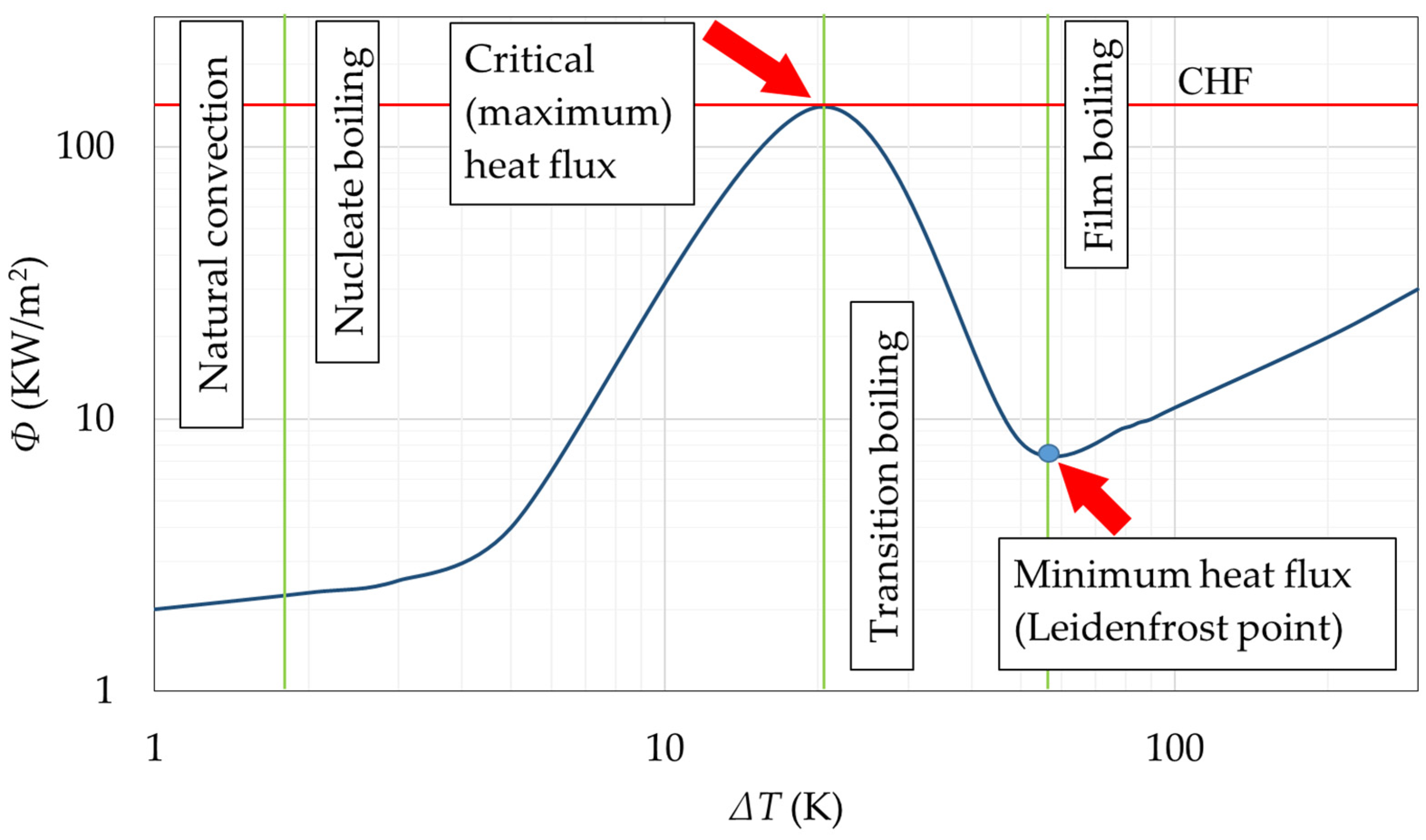
  38. Buchmuller, I. Influence of Pressure on Leidenfrost Effect; Technische Universität: Darmstadt, Germany, 2014. [Google Scholar]
  39. Kim, A.-R. Development of Critical Current Measurement System of HTS Tape Using Pulsed Current. IEEE Trans. Appl. Supercond. 2016, 26, 9001504. [Google Scholar] [CrossRef]
  40. Zhu, J.; Chen, S.; Jin, Z. Progress on Second-Generation High-Temperature Superconductor Tape Targeting Resistive Fault Current Limiter Application. Electronics 2022, 11, 297. [Google Scholar] [CrossRef]
  41. Majka, M.; Kozak, J.; Kozak, S. HTS Tapes Selection for Superconducting Current Limiters. IEEE Trans. Appl. Supercond. 2017, 27, 5601405. [Google Scholar] [CrossRef]
  42. Kar, S.; Rao, V. Step-by-step design of a single phase 3.3 kV/200 A resistive type superconducting fault current limiter (R-SFCL) and cryostat. Phys. C Supercond. Appl. 2018, 550, 107–116. [Google Scholar] [CrossRef]
Figure 1. The layer structure of HTS-2G SF12100-CF tapes [33].
Applsci 13 04323 g001
Figure 2. R(T) characteristics of the tested tapes.
Applsci 13 04323 g002
Figure 3. The intensity of heat dissipation in liquid nitrogen as a function of the temperature difference between the sample and liquid nitrogen [38].
Applsci 13 04323 g003
Figure 4. Scheme of the measuring system and measuring station.
Applsci 13 04323 g004
Figure 5. The tested SF 12100-CF tapes and their mounting method in the measuring holder.
Applsci 13 04323 g005
Figure 6. The principle of short-circuit containment by SFCL.
Applsci 13 04323 g006
Figure 7. Waveforms of current and voltage for the HTS tape: (a) sample in the superconducting state; (b) sample in the resistive state.
Applsci 13 04323 g007
Figure 8. The value of the surge current (I0max) as a function of the expected short-circuit current (Ip) for the tested HTS tapes.
Applsci 13 04323 g008
Figure 9. Example waveforms for the first period of test current pulses (ΔT = 20 ms) for HTS tapes: (a) with a silver layer of 4 μm thickness and (b) with a silver layer of 2 μm thickness.
Applsci 13 04323 g009
Figure 10. Change in the resistance value (R) of the tested tapes during the first 20 ms.
Applsci 13 04323 g010
Figure 11. The value of the minimum limited current (Imin) as a function of the expected short-circuit current (Ip) for the tested HTS tapes.
Applsci 13 04323 g011
Figure 12. Increase in resistance (R) during the operation of the current impulse for the tested HTS tapes.
Applsci 13 04323 g012
Figure 13. The voltage value (Umax) on HTS tapes as a function of prospective short-circuit current (Ip).
Applsci 13 04323 g013
Figure 14. The values of energy (E) dissipated on HTS tapes as a function of the prospective short-circuit current (Ip).
Applsci 13 04323 g014
Figure 15. The dependence of the energy released in the tape as a function of the voltage set on the HTS tape (Umax).
Applsci 13 04323 g015
Figure 16. Dependences of the critical current value of the SF12100-CF tape with 4 µm silver as a function of the number of test current pulse activations for 3, 10, and 25 transitions from the superconducting state.
Applsci 13 04323 g016
Figure 17. Dependences of the critical current value of the SF12100-CF tape with 2 µm silver as a function of the number of test current pulse activations for 3, 10, and 25 transitions from the superconducting state.
Applsci 13 04323 g017
Figure 18. Decrease in the value of the critical current of the HTS 2G tape due to its transition from the superconducting state with test current impulses after 3, 10, and 25 transitions for the HTS tape SF12100-CF (4 µm silver) without electrical insulation.
Applsci 13 04323 g018
Figure 19. Decrease in the value of the critical current of the HTS 2G tape due to its transition from the superconducting state with test current impulses after 3, 10, and 25 transitions for the HTS tape SF12100-CF (2 µm silver) without electrical insulation.
Applsci 13 04323 g019
Figure 20. THS tape sample intended for microscopic examination.
Applsci 13 04323 g020
Figure 21. The images show cross-sections of tape samples obtained with an optical microscope: (a) control sample (Lens: E500: ×1500) and (b) sample subjected to surge currents (Lens: E500: ×700). The corresponding topographic maps are presented below (c,d).
Applsci 13 04323 g021
Figure 22. AFM image of the HTS tape sample subjected to surge currents along with the cross-section in the place marked with red lines 1 and 2.
Applsci 13 04323 g022
Table 1. Parameters of the tested tapes [33].
TapeSF12100-CFSF12100-CF
the thickness of the silver layer4 μm2 μm
width12 mm12 mm
thickness0.105 mm0.105 mm
substrate thickness (Hastelloy)0.1 mm0.1 mm
minimum critical current ICmin (77 K)312 A281 A
Table 2. Structure of buffer layers in tapes SF12100-CF [33].
Buffer LayersLayer Thickness
alumina (Al2O3)~80 nm
yttria YSZ~7 nm
IBAD MgO~10 nm
homo-epi MgO~20 nm
LMO (LaMnO3)~30 nm
Table 3. The value of the surge current I0max, the minimum value of the limited current Imin, the maximum value of the voltage on the sample Umax, and energy E for HTS tapes SF12100-CF (4 μm and 2 μm silver).
Prospective Short-Circuit CurrentSF12100—4 µm Silver
ICmin (77 K) = 312 A
SF12100—2 µm Silver
ICmin (77 K) = 281 A
Ip (A)I0max (A)Imin (A)Umax (V)E (J)I0max (A)Imin (A)Umax (V)E (J)
675527.2195.74.183.3504.6154.54.474.1
810577.8203.75.1112.8517.4160.05.597.4
945617.4212.56.1145.7535.7162.26.5119.0
990636.7222.26.4158.5545.3163.76.8129.1
1035646.2222.26.8169.8552.3167.87.2137.4
1080662.6223.57.1181.5555.9169.57.4145.1
1125667.9228.17.4193.3562.7172.27.8154.3
1170683.3230.27.7207.0565.3172.28.1163.6
Disclaimer/Publisher’s Note: The statements, opinions and data contained in all publications are solely those of the individual author(s) and contributor(s) and not of MDPI and/or the editor(s). MDPI and/or the editor(s) disclaim responsibility for any injury to people or property resulting from any ideas, methods, instructions or products referred to in the content.

