1. Introduction
The statistics on tunnels and underground engineering from the Chinese Society of Civil Engineering show that China has become a world leader in speed and scale in tunnel and underground engineering construction. Against this backdrop, wireless through-the-earth communication has great social value and practical prospects. Accidental collapses are unavoidable during tunnel excavation, especially before the completion of the inverted arch and the secondary lining. Following such an accident, the collapsed rock and soil usually form a wall with a thickness ranging between 50 and 200 m between the tunnel entrance and the construction face, trapping the construction workers. All of the collapsed areas of the tunnel are effectively “cut off”, which severely impedes tunnel clearance and timely rescue. Traditional tunnel entrance communication equipment typically consists of a wired communication method or radio wave communication method, and these involve laying optical cables or communication cables down through tunnel shafts to create a unified wired or wireless communication system for the whole mine. This is currently the most commonly used solution for coal mines. However, when the mine collapses, gas leaks and other serious emergencies occur, and the communication cable is usually destroyed, resulting in the interruption of the traditional wired communication system linking the underground to the aboveground, and rescuers are unable to make timely contact with those trapped underground. As a result, this causes great difficulties in the rescue of personnel, and results in serious bodily injuries and economic losses for China. According to the experts’ estimates, since the foundation of the People’s Republic of China, the economic losses caused by sudden accidents in coal and gold mines in China have exceeded hundreds of billions of CNY, and the death rate is much higher than that in other countries. In recent years, the relevant departments in China have increased mine safety management. However, according to the data released by the State Administration of Work Safety, there are many mining accidents in China every year. Coal mine safety has become a major obstacle for the coal industry. Security has become an urgent problem that must be solved with regard to the industry’s growth. The development of through-the-ground emergency communication is urgently needed to ensure the safety of lives, family happiness, and even the harmonious and stable development of society for the majority of miners in China. The issue of mine safety has also received great attention from the State Council. Therefore, how to create wireless penetrating information transmission through masses of rock and soil from landslides has become an urgent technical issue to be solved in traffic engineering construction at home and abroad [
1,
2,
3,
4,
5].
Currently, research on wireless ground penetrating information transmission at home and abroad mainly includes the following three information transmission methods: (1) an antenna magnetically inducing near-field electromagnetic wave transmission; (2) an elastic wave transmission method using mechanical vibration waves as information carriers; (3) the transmission mode of the electric field of the ground electrode injected via the ground electrode current.
Although the antenna magnetic induction ground-penetrating information transmission method has a large coverage area and small propagation attenuation, it has two important shortcomings in practical applications. On the one hand, the antenna size of this method is huge, requiring a circular antenna with a diameter ranging from 60 m to several kilometers on the ground or underground, which is not suitable for scenes with narrow venues; on the other hand, this method has a high requirement for the layout orientation of the transceiver antenna, and the circular expansion surfaces of the transceiver antenna must be parallel to each other. Therefore, it is only suitable for scenarios such as mine construction, while in scenarios such as mountain tunnel construction, it is almost impossible to deploy a circular antenna on the mountain directly above the trapped person because the antenna must be deployed directly above the underground trapped area [
6,
7].
Elastic wave transmission through the ground does not require a large antenna, is not subject to electromagnetic interference, and is simple to generate signals. However, there are also two application drawbacks. On the one hand, its transmission attenuation is large, it is susceptible to the influence of formation media, and its elastic wave energy utilization efficiency is poor, making it unsuitable for use in complex geological conditions; on the other hand, this method is prone to secondary collapse, so it cannot be applied to wireless strong penetration information transmission in emergency rescue scenarios for tunnel engineering collapse. The information transmission mechanism of the ground electrode current field uses an extremely low-frequency electrical signal, which is applied to the two electrodes driven into the soil layer or the collapsed body of the tunnel, thereby forming a current field in the rock or soil layer, which is detected by the signal at the receiving end. We create a strong penetration wireless information transmission system. For signals with lower carrier frequencies, the field current is dominated by conduction currents, while for signals with higher carrier frequencies, the field currents are dominated by displacement currents so that the wires, electrodes, and the ground form a closed loop, equivalent to a loop antenna, which is similar to the principle of field electromagnetic wave communication.
The characteristics, advantages, and disadvantages of the above three types of wireless strong penetration information transmission technology are compared as shown in
Table 1.
2. Related Work
In the early 20th century, the famous German physicists Arnold Sommerfeld and Hermann Weyl carried out a large number of theoretical analyses and long-term mathematical formula derivations, and finally described the theoretical knowledge of through-the-ground wireless communication in detail, which is based on the assumption of conductive and semi-conductive media. It was proposed on the premise of having uniform electrical properties. In 1930, the U.S. Bureau of Mines set up a research group. Through a large number of experiments, the research group tried to use different sizes and shapes of loop antennas and radio waves of different frequencies, and they finally successfully carried out a 200 m wireless through-the-ground communication experiment. An engineer in South Africa successfully developed the first true penetrating communication system in 1949. The operating frequency of the system was 300 kHz. It also used a loop antenna as a transceiver antenna and its electromagnetic waves to successfully achieve an effective distance of 300 m of penetrating information communication. In 1974, the United States proposed and published a research report entitled “Electromagnetic Communication Through Conductive Strata”, in which the authors reported that they achieved reliable information transmission during underground nuclear explosions via electromagnetic signals through the stratum. Then, the U.S. Bureau of Mines developed an electromagnetic positioning system for locating miners trapped in mines and planned to develop a transmitter with low transmission power and a transceiver with high sensitivity and that was lightweight, which could be attached to the miner. The receiver and the transmitter could maintain communication between the up-hole and the down-hole by penetrating the ground. The 722nd Research Institute of the CSIC is a high-tech engineering technology research institute under the CSIC that specializes in equipment research, manufacturing, and the development and design of communication electronics engineering. The institute is heavily involved with the development and design of integrated communication systems and communication equipment. The wireless chamber emergency rescue communication system is widely used in the field of wireless information transmission under complex geological conditions in coal mines as well as in other mines. In 2013, a through-the-ground communication system was independently developed by the Institute, and a successful experiment was carried out in a mine in Xinzheng, Henan Province, at a depth of 469 m [
8,
9,
10,
11,
12,
13,
14,
15,
16]. In 2013, the Air Force Engineering University conducted a study on the miniaturized antenna of the ground-penetrating information transmission system. When the input power is 0.25 W, the effective transmission distance of the antenna is 30 m, and the maximum transmission distance is 180 m. In 2015, Taiyuan University of Technology conducted research on the propagation characteristics of very low frequency electromagnetic waves at the interface between a mine roadway and ore bed, in the ore bed, and between the ore bed and ground, and established a propagation model of very low frequency electromagnetic waves in the ore bed. In 2016, Beijing Jiaotong University conducted a study on the propagation and attenuation characteristics of electromagnetic waves in the layered media channel and established a layered media model and calculation model. In 2016, Beijing University of Science and Technology conducted research on a very low frequency-coupled information transmission system based on ring antennas and coupled waveguides, proposed an active noise reduction method based on dual-ring antennas, which can achieve 323 m of two-way ground-penetrating coupled information transmission, and conducted theoretical research and simulation on the propagation of electromagnetic waves at different frequencies in different stratum media. In 2017, Xi’an University of Electronic Science and Technology constructed and analyzed a geotechnical channel model, proposed a new spread spectrum weak signal acquisition algorithm, and designed a direct sequence spread spectrum information transmission system based on the current field. In 2018, China University of Mining and Technology designed a wireless underground magnetic induction information transmission system to achieve short-range wireless data transmission in the underground environment. In 2019, the research team designed an anti-multipath interference information system based on a direct sequence spread spectrum. By using highly random Logistic spread spectrum codes, the anti-multipath interference performance of the tunnel engineering ground-penetrating information system was effectively improved. In 2021, Dongkuo University in Seoul, South Korea, developed a practical deployment model for multi-hop magnetic induction wireless underground sensor networks, and evaluated transmitter-to-receiver performance in terms of the signal-to-noise ratio, channel capacity, and bit error rate [
17,
18].
Ground electrode current field communication has the advantages of small antenna size, simple structure, and good flexibility, which can realize a stable communication and long-distance transmission. Relevant research has been carried out continuously both in China and abroad. So far, there are various constraints in the existing technology, which make it incapable of being reliably applied in the closed/collapsed tunnel scenario.
This project is mainly aimed at conducting research work on the strong penetration information transmission requirements in complex geological and electromagnetic environments for emergency rescue scenarios in tunnel engineering. The wireless strong penetration information transmission method based on the ground electrode current field has the characteristics of miniaturization, low power consumption, easy on-site deployment, and relatively long penetration transmission distance. It is suitable for rapid deployment in the event of tunnel engineering collapse accidents, achieving emergency rescue information transmission assurance, and is the best information transmission method in this scenario.
3. Channel Modeling of the Ground Electrode Current Field in a Tunnel Environment
3.1. Analysis of Strong Penetration Technology Based on Ground Electrode Current Injection
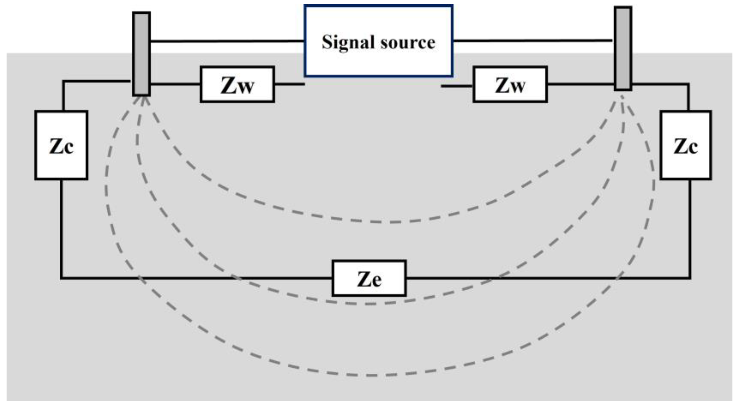
The strong penetration technology based on ground electrode current injection uses extremely low-frequency electrical signals, which are applied to the two electrodes driven into the soil layer or into the collapsed body of the tunnel, thereby forming a current field in the rock layer or soil layer. The signal detection of the terminal achieves the transmission of strong wireless penetration information, as is shown in
Figure 1 [
19].
In the landslide formed by the tunnel construction collapse accident, the penetration environment includes different media, such as rock, sand, reinforced concrete, air cavities, etc., showing the characteristics of non-uniformity. During the transmission of electromagnetic waves in the earth channel, they will be affected by the inhomogeneous media. The interaction between electromagnetic waves and the medium produces various electromagnetic effects, such as polarization, magnetization, and conduction [
20]. The influence of these electromagnetic effects on the transmission of electromagnetic waves is mainly reflected in the reflection, refraction, and attenuation of electromagnetic wave signals. The inhomogeneity of the earth medium, the influence of topographic features, and multipath transmission will all cause signal distortion, fading, or changes in the direction of electromagnetic wave propagation.
The non-uniform earth medium is a semiconductor dielectric material. Since the characteristics of the electrostatic field in the semi-conductive medium are similar to the characteristics of the constant current field in the conductive medium, when studying the propagation characteristics of the conduction current field in the conductive medium, it can be used at a certain time and is observed as a quasi-electrostatic field. Therefore, when studying the information transmission characteristics based on the ground electrode current field, the relevant knowledge of the electrostatic field can be used for analysis [
21].
3.2. Analysis of the Depth of Penetration of Different Electrode Materials and Shapes
The penetration depth of the ground electrode through the ground communication method is related to factors such as the conductivity of the formation, the signal frequency, the intensity of the current injected into the ground, the contact impedance between the electrode and the soil, and the material and shape of the electrode.
Therefore, Chinese and foreign scholars have put forward a lot of ideas and have carried out a lot of research. Yan et al. conducted an electrostatic field analysis of a line source carrying a DC current [
22].
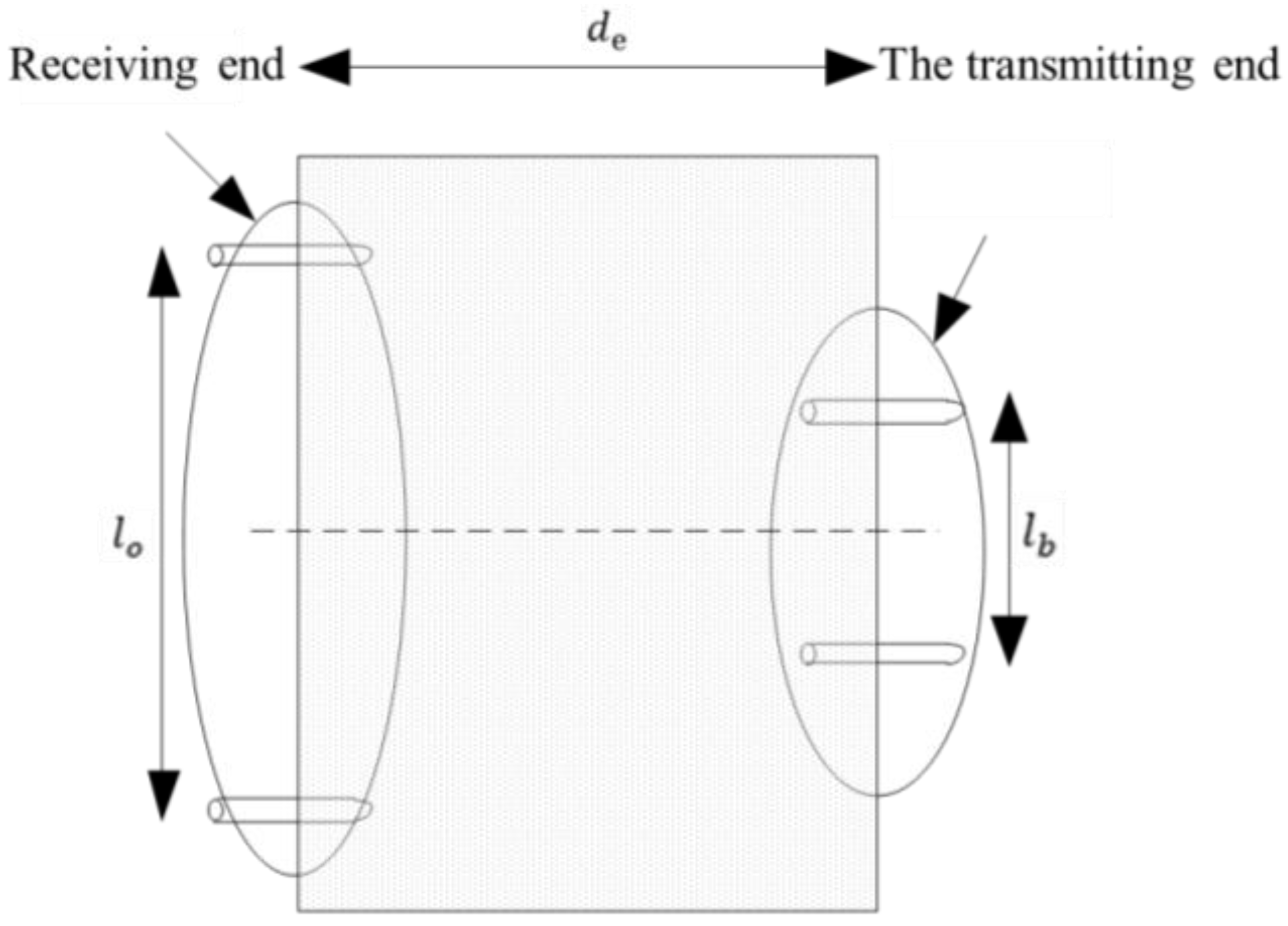
In order to simplify the analysis process, the thick collapsible layer is assumed to be an infinitely uniform conducting medium with a conductivity of
. It is assumed that the pair of transmitting and receiving electrodes can be completely aligned (the direction of the field strength at the receiving point coincides with the baseline of the electric dipole), as shown in
Figure 2, where
is the distance between the transmitting electrodes and the distance between
and the receiving electrodes, and
is the penetration distance [
23].
Then, the electric field strength in an infinite homogeneous medium can be expressed as:
In Formula (1),
, then
,
is the angular signal frequency, and
is the vacuum permeability,
. At the receiving end, the electric dipole is also used to obtain the voltage between the two poles. By integrating the electric field, the receiving voltage can be obtained as: [
24]
In Formula (2), is the emission voltage and represents the contact resistance of the emitter electrode.
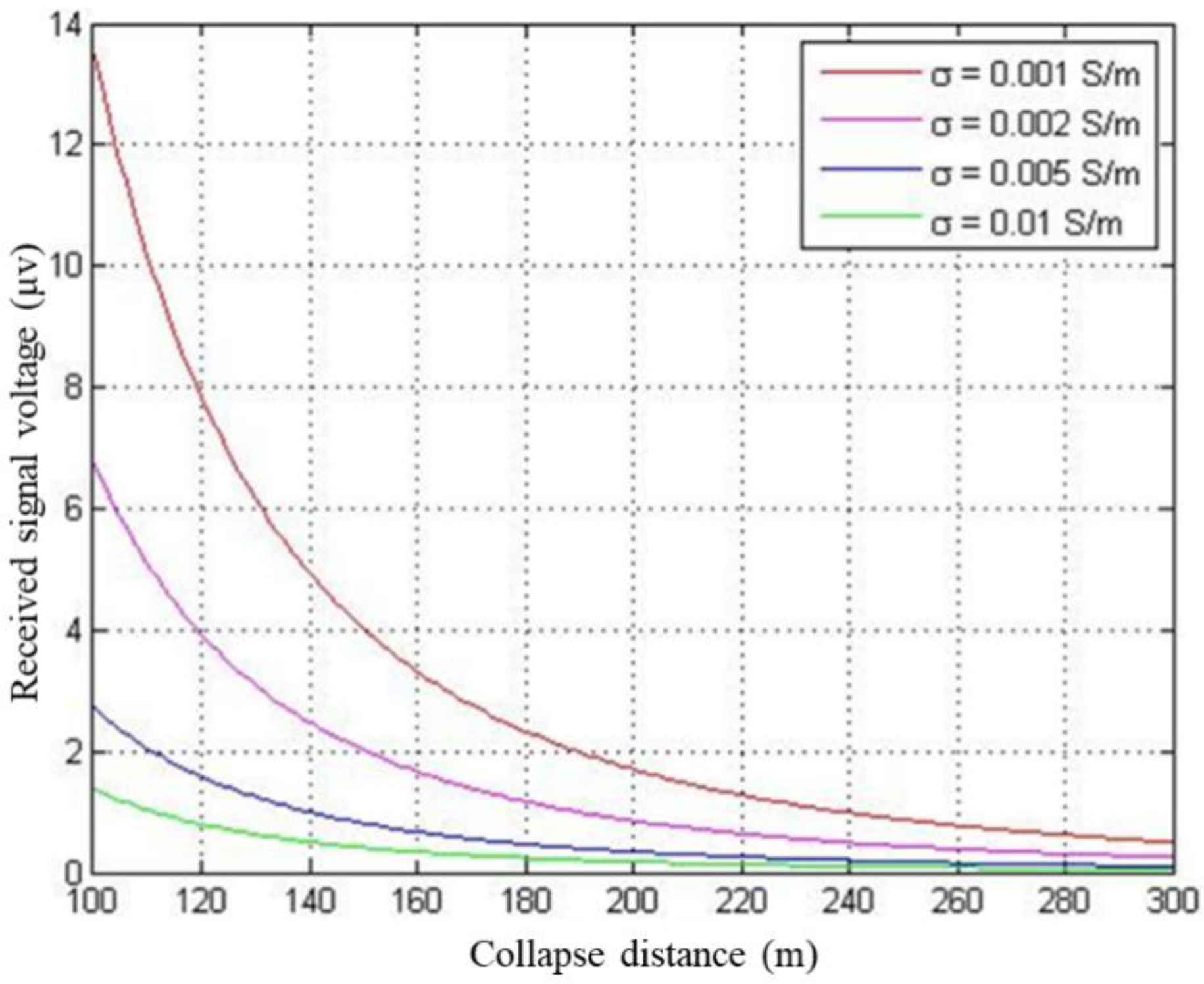
3.3. Simulation Analysis of the Relationship between the Receiving Voltage and Collapse Distance
Figure 3 shows the relationship between the received voltage and the collapse distance. It can be seen from the simulation that under different conductivities, the receiving voltage decreases sharply with the distance, and at a distance of 100 m, the receiving voltage is only μV. This puts forward the requirement for the receiving ability of the system to detect the μV signal.
The path loss based on the ground electrode current field can be expressed as:
Assuming the operating frequency f = 10 Hz, the other conditions remain unchanged except for the penetration distance, the simulation is carried out according to Formula (3), and the simulation results are shown in
Figure 4.
It can be seen from the simulation that the path loss increases significantly with the increase in the penetration distance under different conductivities. According to the relationship between the path loss and the penetration distance, the matching and selection of the power of the transmitter can be guided by the sensitivity of the designed receiving unit [
25].
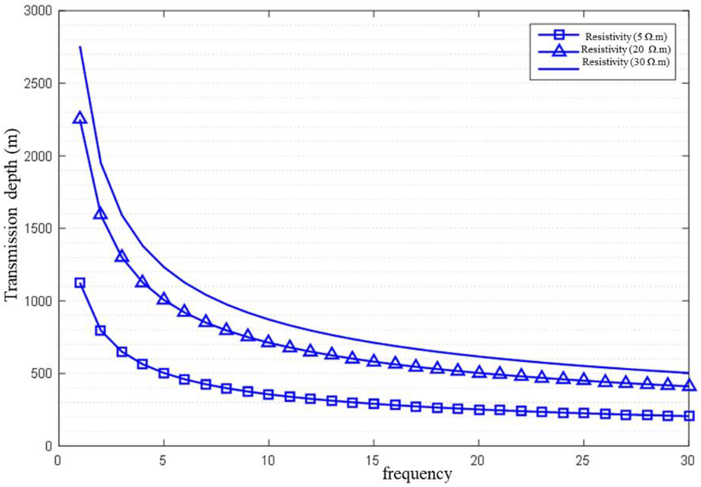
The collapsed medium is not strictly an insulator, so electromagnetic waves can still transmit information. In oil drilling, information transmission based on the ground electrode current field is widely used in MWD. The transmission characteristics of the signal in the ground and in the air are very different. The transmission attenuation in the ground is extremely fast, and the transmission depth of the electromagnetic wave in the ground is at the skin depth of the electromagnetic wave signal in the ground. The skin depth in a homogeneous medium can be expressed as:
Among them,
,
is the frequency, the unit is Hz,
is the formation resistivity, and the unit is
. We select some typical resistivity values (5 Ω·m, 20 Ω·m, 30 Ω·m) according to
Table 2.
The corresponding transmission depth obtained using the simulation is shown in
Figure 5 [
26,
27].
It can be seen from the simulation that, affected by the skin effect, if the resistivity is too small, the penetration ability of the electromagnetic wave signal will deteriorate, and if the resistivity is too high, the radiation power of the ground electrode will be low. When the resistivity is constant, the smaller the frequency, the stronger the signal penetration ability, but the information transmission rate is extremely low [
28].
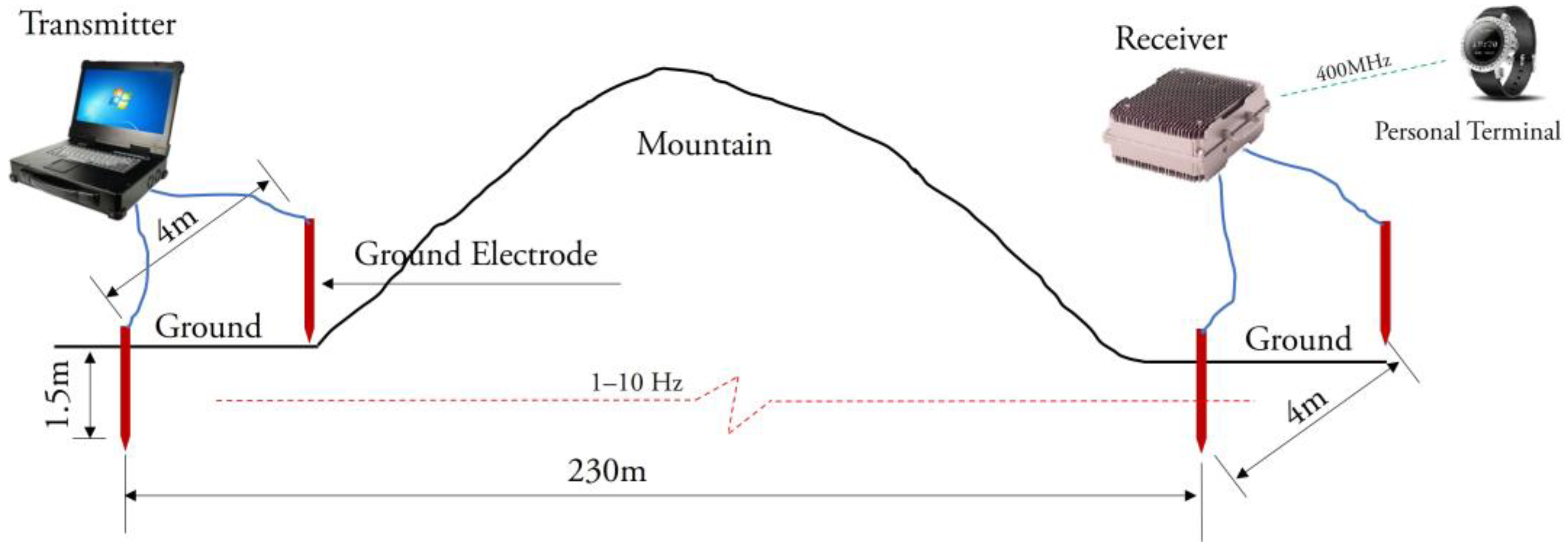
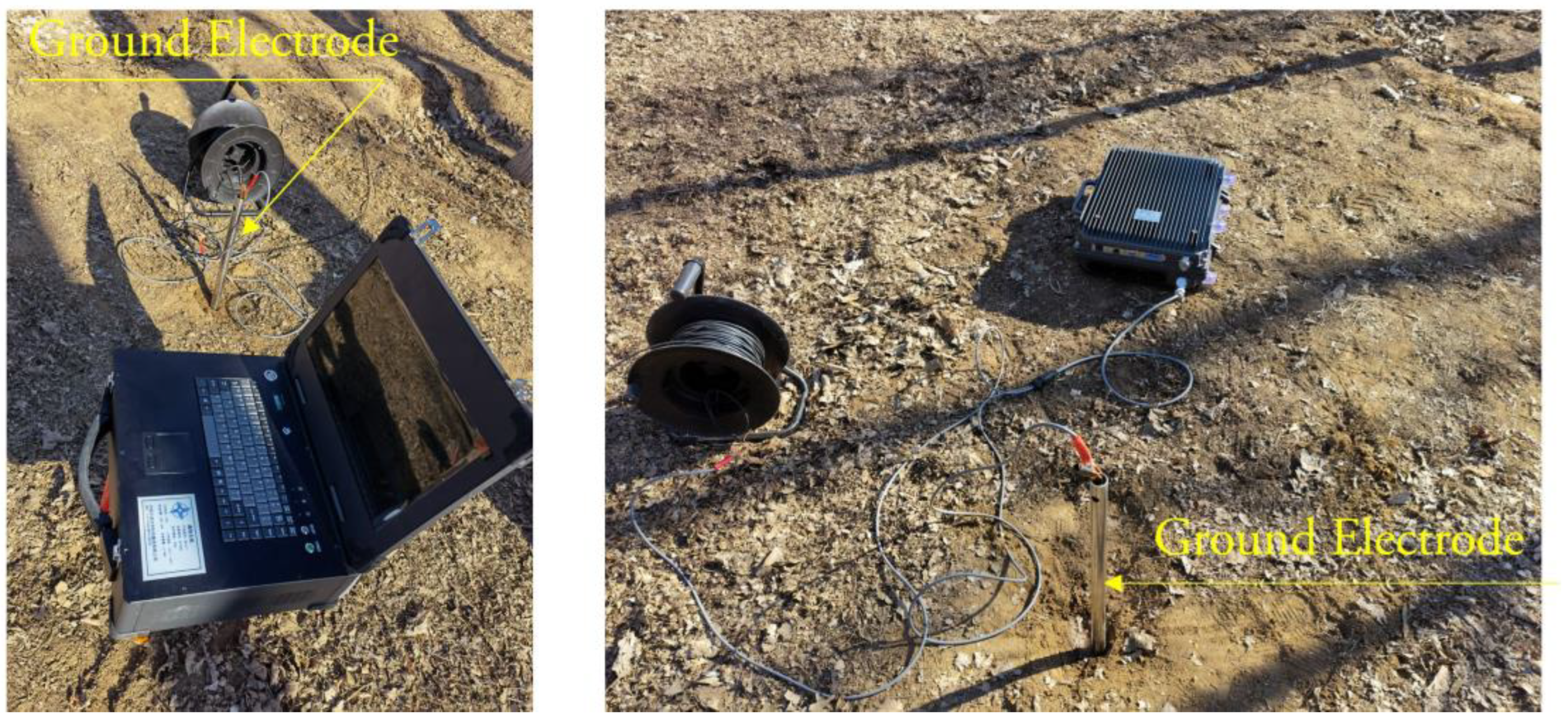
In order to verify the correctness of the path loss proposed in this article, field tests were conducted on both sides of a mountain in Changping District, Beijing. The transmitting end and receiving end of the test are 230 m apart, the ground electrode is 4 m apart, and the ground electrode is driven into the ground at a depth of 1.5 m. The test structure is shown in
Figure 6, and the test environment is shown in
Figure 7.
Transmit a single frequency sine wave signal of 1–10 Hz at the transmitting end, and after receiving the voltage at the receiving end, calculate the path loss at different frequencies according to the path loss formula
PL = −20log
10(|V
receive|/|V
transmit|) and compare it with the theoretical path loss value obtained from Formula (3), as shown in
Figure 8.
As can be seen from
Figure 8, when the transmitter frequency is 1–10 Hz, the theoretically calculated path loss and the actually measured path loss are both above 10 dB, and both increase as the frequency increases. The difference between the actual measurement value and the theoretical calculation value is that in the actual measurement value, the path loss increases with the increase in frequency by a greater amplitude, reaching 7 dB, while the theoretical calculation result is within 1 dB, indicating that in the actual channel, the path loss decreases more severely with frequency, so in order to achieve better reception effects, a lower frequency should be used as the operating frequency of the system.
4. Buried Electrode Scheme Design and Performance Analysis
The current field of the through-the-earth communication system uses electric dipoles to form a loop with the ground, applies a voltage to the loop to obtain an alternating current, and generates a current field in the ground, thereby achieving through-the-earth communication. In the information transmission method based on the ground electrode current field, the grounding method of the antenna is a key factor affecting the information transmission performance. The current intensity formula of the system can be expressed as: [
29]
In Formula (5):
is the emission current (A);
is the emission voltage (V);
is the point dipole ground impedance (Ω); and
is the transmit power (W).
It can be seen from Equation (5) that signal enhancement can be achieved by increasing the power and reducing the grounding resistance. Since the power applied to the electric dipole cannot be infinitely increased, and the safety standard in the tunnel also imposes strict requirements on the transmission power, excessive power cannot be used for transmission. Therefore, a feasible signal enhancement solution is to reduce the ground impedance of the electric dipole antenna.
Its single-ended ground impedance is mainly composed of the impedance of the wire connecting the transmitting device and the electric dipole electrode
, the contact impedance
, and the ground impedance
in series, as shown in Formula (6): [
30]
Among the above resistors, the wire impedance corresponding to electric dipole electrodes can be optimized by using high-performance transmission lines. The earth impedance is related to the medium resistivity, which is not a man-made controllable factor. Therefore, reducing the ground impedance of the electric dipole antenna should mainly start with contact impedance .
There are many ways to reduce . The purpose of reducing the grounding impedance can be achieved by increasing the number of grounding electrodes and increasing the depth of soil penetration.
4.1. Number of Ground Electrodes
Increasing the number of ground electrodes forms an antenna array. The working principle of the antenna array can be regarded as the superposition of electromagnetic waves (electromagnetic fields). For several columns of electromagnetic waves, when they are transmitted to the same area, according to the principle of superposition, the electromagnetic waves will produce vector superposition. The superposition result is not only related to the amplitude of each column of electromagnetic waves, but also to the phase difference between them in the encounter interval.
For an electric dipole whose shape, size, and surrounding environment are determined, its contact resistance can be generally expressed as follows:
In Formula (7): the function is determined by the shape and size of the electrode rod, 1/m; is the soil conductivity, S/m.
Therefore, the contact impedance of the electric dipole antenna is related to its shape and size and the conductivity of the surrounding earth. The contact resistance can be reduced by increasing the conductivity of the surrounding soil and changing the shape and size of the electric dipole. However, it is difficult for humans to change the conductivity of the earth for a long time and on a large scale. Therefore, to change the size of the contact resistance, the shape function of the ground electrode needs to be changed .
For a horizontally arranged cylindrical electrode with a length of
, a diameter of
, and a buried depth of
, its grounding impedance can be expressed by the potential midpoint method. Its model is shown in Formula (8):
For electrodes buried on the surface, when the buried depth
h is negligible, the model expression can be simplified to Equation (9):
Multiple electrodes can be used in parallel to increase the contact area between the electrodes and the ground, thereby reducing the ground impedance of the electric dipole antenna. For multiple electrodes in parallel, the grounding impedance can be expressed as:
Formula (10):
is the grounding impedance of a single electrode, Ω;
is the number of grounded clicks; and
is the utilization factor of the grounding body, which is related to the shape, quantity, and position of the grounding electrode.
It can be seen that with the increase in the number of parallel electrodes, the contact area between the electrodes and the ground increases, and the ground impedance of the electric dipole antenna decreases.
4.2. Ground Electrode Depth
To calculate the impedance of the buried electrode, see Equation (11):
For this model analysis, the effects of the following variables on the electrode impedance formula are considered: where is the soil conductivity, is the depth of the ground electrode, is the radius of the ground electrode, and is the separation distance between the two vertical electrode rods. The model reflects the effect of the insertion depth of the ground electrode on the impedance between electrodes.
5. Conclusions
Through the channel modeling of the ground electrode current field in the tunnel environment and the analysis of the buried electrode, various factors affecting the information transmission characteristics of the ground electrode current field are analyzed.
- (1)
Under different conductivities, the receiving voltage decreases sharply with the distance, and at a distance of 100 m, the receiving voltage is only μV. This puts forward the requirement for the receiving ability of the system to be able to detect the μV signal.
- (2)
Under different conductivities, the path loss increases significantly with the increase in the penetration distance. According to the relationship between the path loss and the penetration distance, the matching and selection of the transmitter power can be guided by the designed sensitivity of the receiving unit.
- (3)
Affected by the skin effect, if the resistivity is too small, the penetration ability of the electromagnetic wave signal will deteriorate, and if the resistivity is too high, the radiation power of the ground electrode will be low. When the resistivity is constant, the smaller the frequency, the stronger the signal penetration ability, but the information transmission rate is extremely low.
- (4)
As the number of parallel electrodes increases, the contact area between the electrodes and the ground increases, and the ground impedance of the electric dipole antenna decreases.
- (5)
The insertion depth of the ground electrode will affect the impedance between the electrodes. Therefore, variables, such as soil conductivity, depth of the ground electrode, radius of the ground electrode, and separation distance between the two vertical electrode rods must be considered.
Through the research of this project, using the research results, we have developed and produced an engineering prototype that can penetrate underground projects and facilities such as mines or tunnels with a thickness of 1000 m of collapse and surrounding rock and conduct instant interactive text communication with a single piece of self-compiled information that does not exceed 24 characters. It solves the communication problems between rescuers and trapped personnel after accidents in underground projects and facilities within mines or tunnels, before and during rescue operations, and provides accurate information and communication guarantees for decision-makers to formulate scientific and accurate rescue plans and programs. It will definitely make outstanding contributions to the emergency rescue of underground projects in China and the world in the future.
Author Contributions
J.H.: visualization, data curation, formal analysis, writing original draft. H.Y.: investigation, resources, funding acquisition. Z.S.: supervision, project administration. B.Z.: conceptualization, validation. Z.K.: methodology, supervision. P.S.: software. All authors have read and agreed to the published version of the manuscript.
Funding
This work was supported by the special fund for safe production of China Communications Construction Corporation (BC2020000583).
Institutional Review Board Statement
Not applicable.
Informed Consent Statement
Informed consent was obtained from all subjects involved in the study.
Data Availability Statement
The dataset can be accessed upon request.
Conflicts of Interest
No conflict of interest exist in the submission of this manuscript, and this manuscript has been approved by all authors for publication.
References
- Sun, J.; Zhang, G. Mine emergency communication system. Ind. Min. Autom. 2019, 45, 1–5. [Google Scholar]
- Meng, J. Design and Implementation of Current Field Mine Through-Ground Spread Spectrum Communication System. Master’s Thesis, Harbin Engineering University, Harbin, China, 2017. [Google Scholar]
- Fu, T.; Liu, B.; Wang, Y. A review of research on wireless communication through the ground. Sci. Technol. Eng. 2021, 21, 6993–7001. [Google Scholar]
- Durkin, J. Apparent Earth Conductivity over Coal Mines as Estimated from Through-the-Earth Electromagnetic Transmission Tests, PB84—213792; The United States Department of the Interior, Bureau of Mines: Pittsburgh, PA, USA, 1984. [Google Scholar]
- Liu, B.; Fu, T.; Wang, Y. Mathematical modeling and analysis of electric field for electric field through ground communication. Sci. Technol. Eng. 2021, 21, 12997–13001. [Google Scholar]
- Bataller, V.; Munoz, A.; Gaudo, P.M.; Mediano, A.; Cuchí, J.A.; Villarroel, Y.J.L. Electrode impedance measurement in through-the earth communication applications. IET Microw. Antennas Propag. 2012, 6, 807–812. [Google Scholar] [CrossRef]
- Jiang, Y.-z.; Zhao, P.; Zhai, Q.; Ying, W.-w.; Hu, Q.-l. Signal enhancement techniques for through-the-earth communication based on multiple references and beam forming. Int. J. Electron. Commun. 2018, 86, 86–91. [Google Scholar] [CrossRef]
- Bataller, V.; Muñoz, A.; Molina-Gaudó, P.; Mediano, A.; Cuchí, J.A.; Villarroel, J.L. Improving Medium Access in Through-the-Earth VLF-LF Communications. J. Commun. 2009, 4, 284–294. [Google Scholar] [CrossRef] [Green Version]
- Yan, L.; Waynert, J.A.; Sunderman, C. Measurements and modeling of through-the-earth communications for coal mines. IEEE Trans. Ind. Appl. 2013, 49, 1979–1983. [Google Scholar] [CrossRef]
- Van, L.; Sunderman, C. Electric field of grounded horizontal line transmitter for through-the-earth communication. In Proceedings of the 31st International Review of Progress in Applied Computational Electromagnetics (ACES), Williamsburg, VA, USA, 22–26 March 2015; pp. 22–26. [Google Scholar]
- Hil, D.A. Electromagnetic Scattering by Buried Objects of Low Constracst. IEEE Trans. Geosci. Remote Sens. 1988, 26, 195–203. [Google Scholar] [CrossRef] [Green Version]
- Gogoi, A.; Raghuram, K. Analysis of VLF Loop Antennas on the Earth Surface for Underground Mine Communication. In Proceedings of the Antennas and Propagation Society International Symposium, Baltimore, MD, USA, 21–26 July 1996; pp. 962–965. [Google Scholar]
- Gogoi, A.; Raghuram, K. Variation of field strength in underground mine area on the size of VLF loop antennas laid on the Earth surface. In Proceedings of the Antennas and Propagation Society International Symposium, Montreal, QC, Canada, 13–18 July 1997; pp. 1792–1795. [Google Scholar]
- Zhang, Y.; Kim, Y.-H.; Jiang, J. Numerical simulation of dispersion characteristics of two-dimensional TLM grids. Microw. J. 2000, 16, 178–181. [Google Scholar]
- Zhang, Y.; Kim, Y.-H.; Jiang, J. Simulation of two-dimensional and three-dimensional electromagnetic scattering near-field and far-field by TLM method. Microw. J. 2000, 16, 249–254. [Google Scholar]
- Al-Mukhtar, D.A.; Sitch, J.E. Transmission-line matrix method with irregularly graded space. IEEE Proc. 1981, 128 Pt H, 299–305. [Google Scholar] [CrossRef]
- Liu, Y.; Liu, F.; Yang, D.; Xu, J.; Zhang, Z. Type of active impulse noise suppressing method based on double-loop antennas in very low frequency/ultra-low frequency coupling communications. IET Microw. Antennas Propag. 2017, 11, 867–873. [Google Scholar] [CrossRef]
- Ishtiaq, M.; Hwang, S.-H. Performance Analysis of Multihop Underground Magnetic Induction Communication. Electronics 2021, 10, 1255. [Google Scholar] [CrossRef]
- Johns, P.; Beurle, A.L. Numerical solution of 2-dimensional scattering problems Using a transmission-line matrix. Proc. IEEE 1971, 119, 1203–1208. [Google Scholar] [CrossRef]
- Christopoulos, C. The Transmission-Line Modeling Method; IEEE Microwave Theory and Techniques Society: New York, NY, USA, 1995; pp. 61–90. [Google Scholar]
- Geyer, R.G. Theory and Experiments Relating to Electromagnetic Fields of Buried Sources with Consequences to Communication and Location. In Proceedings of the Through-the-Earth Electromagnetic Workshop, Golden, CO, USA, 15–17 August 1973; pp. 20–33. [Google Scholar]
- Wait, J.R.; Spies, K.P. Electromagnetic field of a small loop buried in a stratifeid earth. IEEE Trans. Antennas Propag. 1971, 21, 717–718. [Google Scholar] [CrossRef]
- Wait, J.R. Electromagnetic induction technique for locating a buried source. IEEE Trans. Geosci. Electron. 1971, 9, 95–98. [Google Scholar] [CrossRef]
- Sun, J. Coal mine safety production monitoring and communication technology. Chin. J. Coal 2010, 35, 1925–1929. [Google Scholar]
- Sun, J. Modern mine communication technology and system. Ind. Min. Autom. 2013, 39, 1–5. [Google Scholar]
- Xin, X.; Yi, L.; Elementary, Y.K. Analysis of communication channel of underground current field through rock formation. Coalf. Geol. Explor. 2005, 33, 77–79. [Google Scholar]
- Cheng, Y.; Dong, S.; Zhang, S. Application of ultra-low frequency electromagnetic wave remote sensing detection technology in coal exploration. Geophys. Geochem. Explor. 2009, 2, 38–42. [Google Scholar]
- Hao, J.; Wang, F. Multipath characteristics of layered earth channel for elastic wave through-the-earth communication. Chin. J. Coal 2012, 37, 695–699. [Google Scholar]
- Tao, J. Discussion on some problems of wireless communication system of very low frequency electromagnetic wave penetrating the formation. J. Taiyuan Univ. Technol. 2000, 31, 690–693. [Google Scholar]
- Tao, J. Research on antenna device of VLF electromagnetic wave penetrating formation wireless communication system. J. Taiyuan Univ. Technol. 1999, 30, 141–145. [Google Scholar]
| Disclaimer/Publisher’s Note: The statements, opinions and data contained in all publications are solely those of the individual author(s) and contributor(s) and not of MDPI and/or the editor(s). MDPI and/or the editor(s) disclaim responsibility for any injury to people or property resulting from any ideas, methods, instructions or products referred to in the content. |
© 2023 by the authors. Licensee MDPI, Basel, Switzerland. This article is an open access article distributed under the terms and conditions of the Creative Commons Attribution (CC BY) license (https://creativecommons.org/licenses/by/4.0/).


