Communication

A Compact Size Antenna for Extended UWB with WLAN Notch Band Stub

1
Department of Information and Communication Engineering, Chungbuk National University, Cheongju 28644, Republic of Korea
2
Department of Smart Device Engineering, Sejong University, Seoul 05006, Republic of Korea
3
Department of Information and Communication Engineering, Kongju National University, Gongju-si 32588, Republic of Korea
*
Author to whom correspondence should be addressed.
Appl. Sci. 2023, 13(7), 4271; https://doi.org/10.3390/app13074271
Submission received: 16 February 2023 / Revised: 23 March 2023 / Accepted: 26 March 2023 / Published: 28 March 2023
(This article belongs to the Special Issue Design, Analysis, and Measurement of Antennas)

Abstract

:
An ultra-wideband (UWB), geometrically simple, compact, and high-gain antenna with a WLAN notch band is presented for future wireless devices. The antenna is printed on the top side of the Rogers RT/Duroid 5880 substrate and has a small dimension of 10 mm × 15 mm × 0.254 mm. The primary radiator of the proposed coplanar waveguide-fed monopole antenna is comprised of a rectangular-shaped structure initially modified using a slot, and its bandwidth is further enhanced by loading a Y-shaped radiator. As a result, the antenna offers a –10 dB impedance matching bandwidth of 11.55 GHz ranging from 3–14.55 GHz, covering globally allocated C-, S-, and X-band applications. Afterward, another rectangular stub is loaded in the structure to mitigate the WLAN band from the UWB spectrum, and the final antenna offers a notched band spanning from 4.59 to 5.82 GHz. Moreover, to validate the simulated results, a hardware prototype is built and measured, which exhibits good agreement with the simulated results. Furthermore, the proposed work is compared to state-of-the-art antennas for similar applications to demonstrate its design significance, as it has a compact size, wider bandwidth, and stable gain characteristics.

1. Introduction

The recent evolution in wireless communication systems has urged us to revise the requirements for designing communicating gadgets. The high data rate transfer with low latency and low power consumption in ultra-wideband (UWB) technology has opened doors for many applications in modern society [1,2]. The UWB technology is not limited to satellite communication or military purposes, but it also finds many applications, ranging from biomedical imaging to wireless sensor networks [3,4,5]. Thus, having an eye on the advantages of the UWB spectrum, a number of antennas have been proposed in the literature [6,7,8,9,10,11,12].
The UWB antennas presented in [6,7,8] have larger physical dimensions and do not cover the UWB spectrum (3.1 GHz to 10.6 GHz) allocated globally. Thus, it results in limiting their application to modern-day compact electronics. On the other hand, the compact-sized antennas designed in [9,10] have drawbacks of structural complexity, low gain, and unstable performance, while others have the disadvantage of limited bandwidth [11,12]. Moreover, it is necessary to design notch band UWB antennas due to the existence of sub-bands inside the UWB spectrum, like Wireless Local Area Network (WLAN), Wireless Fidelity (Wi-Fi), Worldwide Interoperability for Microwave Access (WiMAX), and Industrial, Scientific, and Medical (ISM) bands. Wi-Fi interference with UWB spectrum may also cause several co-existence issues like packet capturing and degraded performance [13,14]. It is noted that the UWB antennas proposed in [6,7,8,9,10,11,12] do not offer on-demand notch band functionality. Therefore, a lot of research has been done in designing new antennas for UWB spectrum with notching characteristics. Since the 5 GHz band spectrum is widely used for a number of applications, there is a dire need to mitigate this band from the UWB region to minimize the interference with the UWB communication systems. Therefore, various UWB antenna systems in the literature [15] are focusing on efficient antenna systems offering low interference. Hence, to meet the requirement of present day UWB applications, UWB antennas should offer notch band functionality without sacrificing overall antenna performance in terms of bandwidth, gain, and stable radiation pattern [16,17].
Several UWB antennas with WLAN notch band characteristics that have the advantages of compact electrical size have been widely investigated in the literature [18,19,20,21,22,23,24,25,26,27,28,29,30]. For instance, a circular patch antenna that has a balanced notch band feature with a common mode suppression is presented in [18]. A stub-loaded circular patch-based antenna was designed to achieve UWB mode. Afterward, a bandpass filter was designed in such a way that the resonator is judiciously fed, resulting in a common notch band behavior. However, due to the utilization of a filter, the overall size of the antenna gets increased, and the optimized antenna offers a physical size of 29.38 mm × 28.25 mm. Likewise, a circular-shaped monopole antenna is designed in [26] to achieve wide operational mode ranges from 2.8–12 GHz, while an enhanced mushroom-like modified Electromagnetic Band Gap (EBG) structure is utilized to notch the desired band. However, the reported antenna has several drawbacks, including structural complexity and a larger physical dimension of 40 mm × 50 mm.
A rectangular-shaped quarter-wave monopole antenna was modified using two consecutive iterations of slots to design a modified W-shaped fractal antenna for UWB applications [27]. Additionally, a pair of two inverted L-shaped open-ended stubs were loaded with a ground plane to achieve notch band functionality. The resulting antenna operates from 3–12 GHz, a notched band of 5.2–5.8 GHz, and a set back of a large overall size of 31 mm × 27 mm. On the other hand, a multi-layered Artificial Magnetic Conductor (AMC) loaded UWB antenna is presented in [28]. At first, a rectangular monopole was modified using truncated corners to widen the bandwidth, then two modified U-shaped slots were etched to achieve a notch band, and finally, an AMC was loaded to enhance the performance of the antenna. Having the advantage of high gain and two notch bands, the antenna still has some disadvantages, including its limited bandwidth of 4.8–10 GHz and its large physical size of 33 mm × 33 mm, with an overall critical height of 7 mm.
Last but not least, a pac-man-shaped printed UWB antenna was designed to achieve two distinct notch bands [29]. However, the notch band does not have the potential for practical usage due to poor comparison between simulated and measured results.
Winding up the whole discussion, there is still a need for a UWB antenna that has notch band functionality without degrading the other design constraints like compact size, wideband, geometrically simple, high gain, and stable radiation patterns. Thus, an antenna having a wide operational bandwidth with a WLAN notch band characteristic is proposed in this paper. The organization of the remaining manuscript is as under. The design methodology of the proposed UWB antenna and respective results are presented in Section 2, while the performance parameters are analyzed in Section 3. Furthermore, Section 4 contains the comparison of the proposed work with the state-of-the-art, while the manuscript is concluded in Section 5, followed by references.

2. Design Methodology of the UWB Antenna

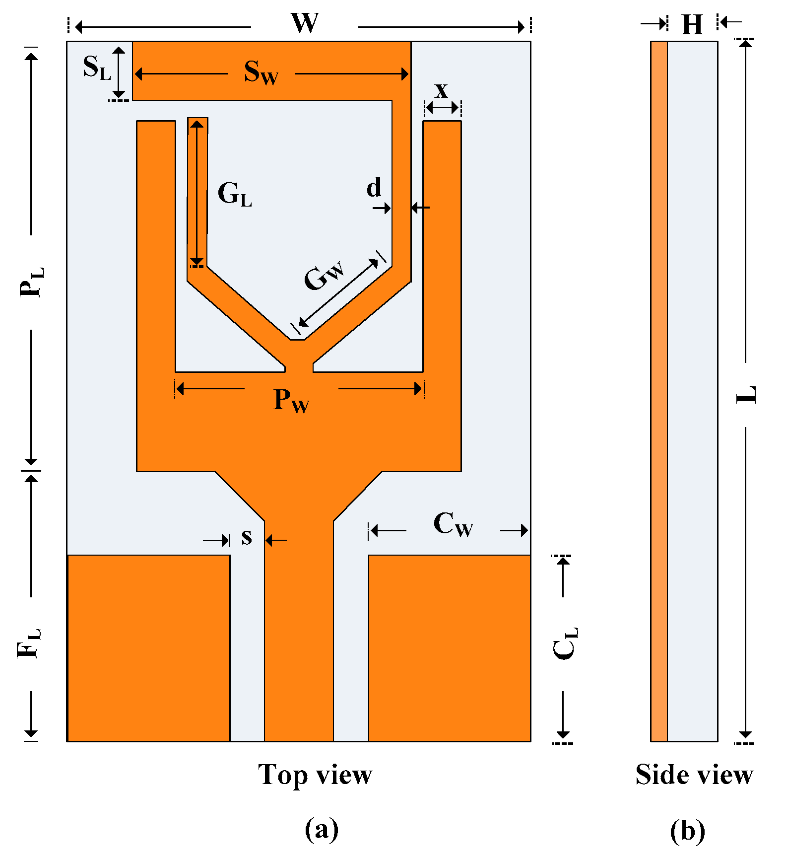
2.1. Geometry of the Proposed Antenna

The top and side perspectives of the presented UWB antenna are depicted in Figure 1. The antenna has a small footprint of only 15 mm × 10 mm (L × W). The antenna geometry has a relative electrical permittivity and a loss tangent of 2.2 and 0.002, respectively, with a thickness of 0.254 mm, and is etched on the Rogers 5880/Duroid substrate. The proposed UWB antenna consists of a Coplaner Waveguide (CPW) feedline and a rectangular patch with several stubs and slots. An additional stub is added to the modified rectangular patch radiator to enhance impedance bandwidth and get WLAN spectrum rejection. The proposed antenna is of the CPW feedline which allows for the inherent advantages of broadband performance, decreased dispersion, and ease of manufacture.
The following are the optimal dimensions of the proposed notch band UWB antenna: W = 10, L= 15, H = 0.254, Pl = 9.2, Pw = 5.4, CL = 4, CW = 3.5, s = 0.75, x = 0.8, SL = 1.25, SW = 6, d = 0.4, GL = 3.19, and GW = 2.65 (All dimensions are in millimeters).

2.2. Antenna Design Steps

The design methodology steps and their respective s-parameters are shown in Figure 2. The proposed work consists of two major phases. Phase 1 consists of designing a compact size UWB antenna, which is further utilized in phase 2 to achieve UWB behavior with a WLAN notch band spectrum.
Initially, a conventional quarter-wave monopole antenna that has a rectangular radiator was designed. The commercially available CST Microwave Studio software was used to perform the antenna simulations. The antenna is CPW-fed, a potential feeding technique to achieve compact size, easy design, and broadband impedance matching. Moreover, its uni-planar structure also eases its integration with electronic circuitry. The respective length of the rectangular radiator for the desire frequency is estimated using the following equation provided in [30]:
L fo = c 4 f o e ff
where c refers to the speed of light in the vacuum and fo is the central resonating frequency of 6.5 GHz. Furthermore, e ff is the constant representing the effective dielectric constant whose value can be approximated using Equation (2) [31]:
e f f   e r + 1 2
After a slight optimization in parameters owing to the losses in the substrate material, the antenna offers a broad bandwidth of 5.4–8.2 GHz, as depicted in Figure 2b. Afterward, a slot was etched from the radiator, as shown in Figure 2a. This helps to achieve a further wider bandwidth without affecting the overall size of the antenna. The slot results in a Y-shaped radiator, which is also a potential structure to achieve wide impedance matching to cover UWB frequency band. The working principle of the Y-shaped radiator is explained in [32]. As shown in Figure 2b, the antenna now has a |S11| −10 dB impedance bandwidth of 4.8–9.4 GHz.
In the final step in designing the proposed UWB antenna, a rectangular stub on a Y-shaped radiator is introduced, as shown in Figure 2a. The antenna operates between 5 and 14 GHz, covering more than 85% of the UWB spectrum and extended UWB spectrums of 11 and 13 GHz, as recommended by the International Telecommunication Union (ITU) [33]. Finally, to avoid the interference of the UWB antenna with sub-bands lying inside the UWB spectrum, a rectangular stub was loaded on the top side of the radiator, which notches the globally allocated WLAN band spectrum of 5.25–5.85 GHz [34]. This specific frequency band spectrum covers 4.9 GHz and 5 GHz Wireless LAN (WLAN) accessed using IEEE 802.11 communication protocols. This spectrum has a number of frequency channels, each having a dynamic bandwidth of 10 MHz, 20 MHz, 40 MHz, 80 MHz, and 160 MHz, respectively. The Radio Standard Specification (RSS) provides a transmitter output power line and equivalent isotropically radiated power (EIRP) requirements, limiting the maximum EIRP peak value to 4 Watts. Therefore, the wireless signals from WLAN spectrum have the ability to interfere with the UWB spectrum. Furthermore, the notched band channels also have weather radars operating in these bands. Thus, the most congested part of the WLAN band spectrum 4.9 GHz (802.11j) and 5 GHz (802.11a/h/j) from channel 7 to channel 161 is attenuated for low interference with the UWB spectrum. Final optimization was done to achieve the maximum possible bandwidth while keeping the notch band constant. The proposed antenna offers UWB ranges from 3–14.55 GHz, having a notched band of 4.59–5.82 GHz, as depicted in Figure 2b.

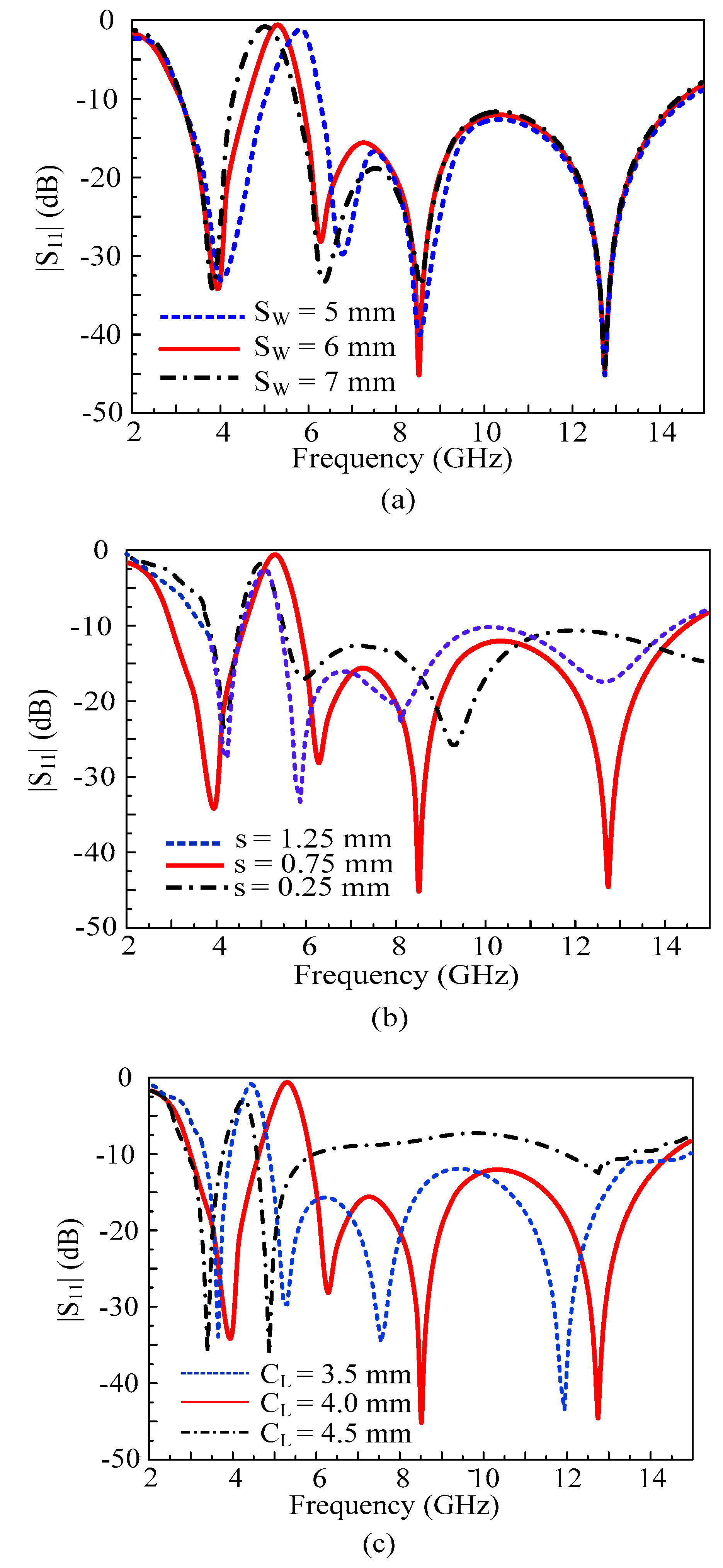
2.3. Parametric Analysis

As stated earlier, the additional stub loaded at the top edge of the UWB radiator is responsible for the notch band behavior. Thus, to further demonstrate the findings, a parametric analysis was done by varying the length of the stub (SW), and the corresponding |S11| results are depicted in Figure 3a. It can be observed from Figure 3a that when the optimized length of the stub is increased, the notch band shifts towards the left side, while the bandwidth of the notched area remains unchanged. Similarly, when the length of the stub is reduced, the notch band shifts toward the left side. When the electrical dimensions of an antenna are reduced, it results in a frequency response shift towards the right end.
Figure 3b,c demonstrate the |S11| results with respect to the variations in gap (s) and the length CL. The characteristic impedance Zo of the coplanar waveguide varies as its dimensions (s and CL) are varied. When the gap length is decreased, the notch band is shifted towards the lower end of the spectrum. Furthermore, it also causes a decrease in the bandwidth of the antenna due to mismatching of the impedance. However, when the gap length is increased, the bandwidth of the antenna decreases, and the notch band is shifted towards the left side. Similarly, when the length CL is increased from the optimized value, the notch band shifts towards the left side.

3. Results and Discussions

3.1. Hardware Prototype and Measurement Setup

To verify simulated results, the hardware prototype of the proposed compact antenna was fabricated using a commercially available substrate. Then, the return loss of the proposed work was measured using Vector Network Analyzer (VNA), while far-field parameters, including gain and radiation pattern, were measured using an electromagnetically isolated RF anechoic chamber. Figure 4 depicts the fabricated prototype along with the far-field measurement setup.

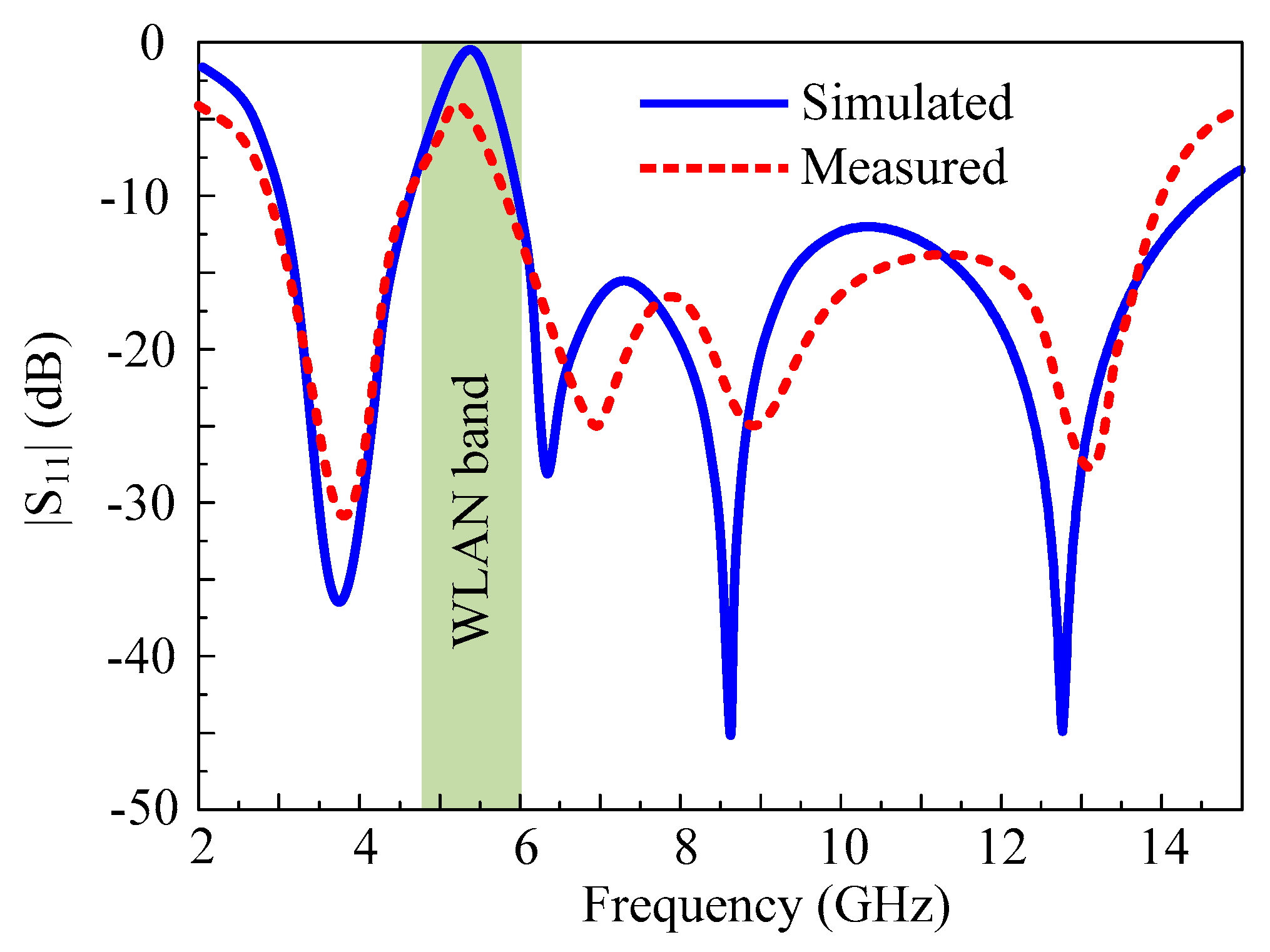
3.2. Reflection Coefficient
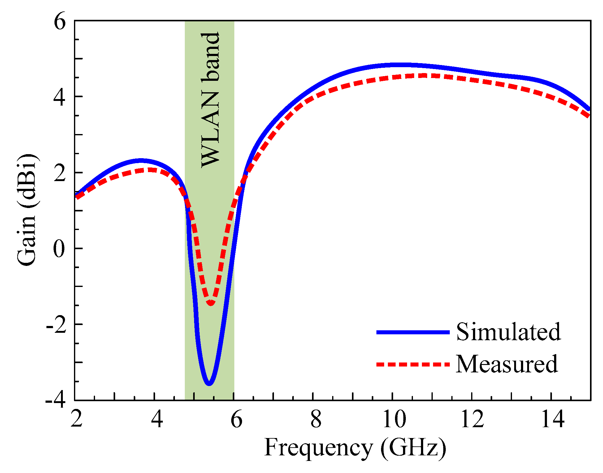
A comparison among simulated and measured reflection coefficient of the antenna is presented in Figure 5. It can be seen clearly that the antenna offers an ultra-wideband spectrum of 3–14.32 GHz when measured, having a notched band ranging from 4.59–5.82 GHz. Moreover, a strong comparison between simulated and measured results validates the findings.

3.3. Gain

The gain comparison of the proposed antenna for both simulated and measured values for the complete working region is depicted in Figure 6. The antenna has a simulated gain of more than 2 dBi in the resonating bandwidth, but it begins to decrease in the notch band, reaching a low of −3.9 dB at 5.5 GHz. The measured value of the gain also depicts similar results for both resonating and notch bandwidths. The antenna gain and far-field radiation characteristics are measured in an anechoic facility. A well-calibrated regular gain horn antenna was placed in the anechoic facility and utilized as a transmit antenna, whereas the prototype antenna acts as a receiver antenna. Low noise amplifiers were utilized for the provision of constant power reception. The antenna was rotated at a number of angles to measure the results at various configurations.

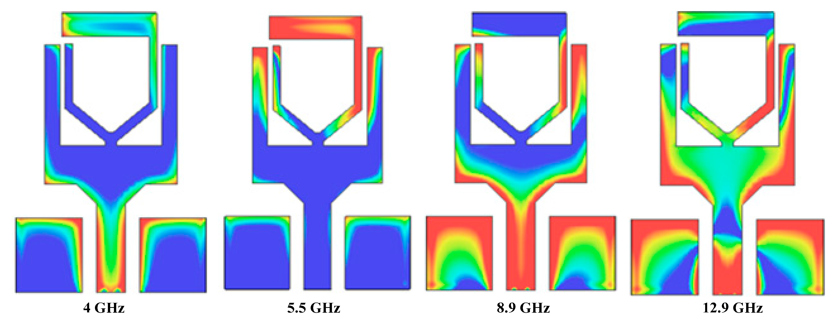
3.4. Surface Current Distribution

To further understand the resonating behavior of the proposed antenna, Figure 7 illustrates surface current distribution at various resonating and notch band frequencies. It can be observed that at the lower resonance of 4 GHz, the current distribution is lower at the upper part of the radiator, which results in the generation of that frequency. Contrary to that, at the notch band, the current show maximum value around the upper stub and across it, while at the lower side, almost no current distribution is available. This causes the mitigation of the 5.5 GHz band. Furthermore, it can also be observed from Figure 7 that current is distributed across the radiator, which causes the generation of a higher resonance. Hence, it is also verified that the upper stub (rectangular stub) is responsible for mitigating the WLAN band from the UWB spectrum.

3.5. Radiation Pattern
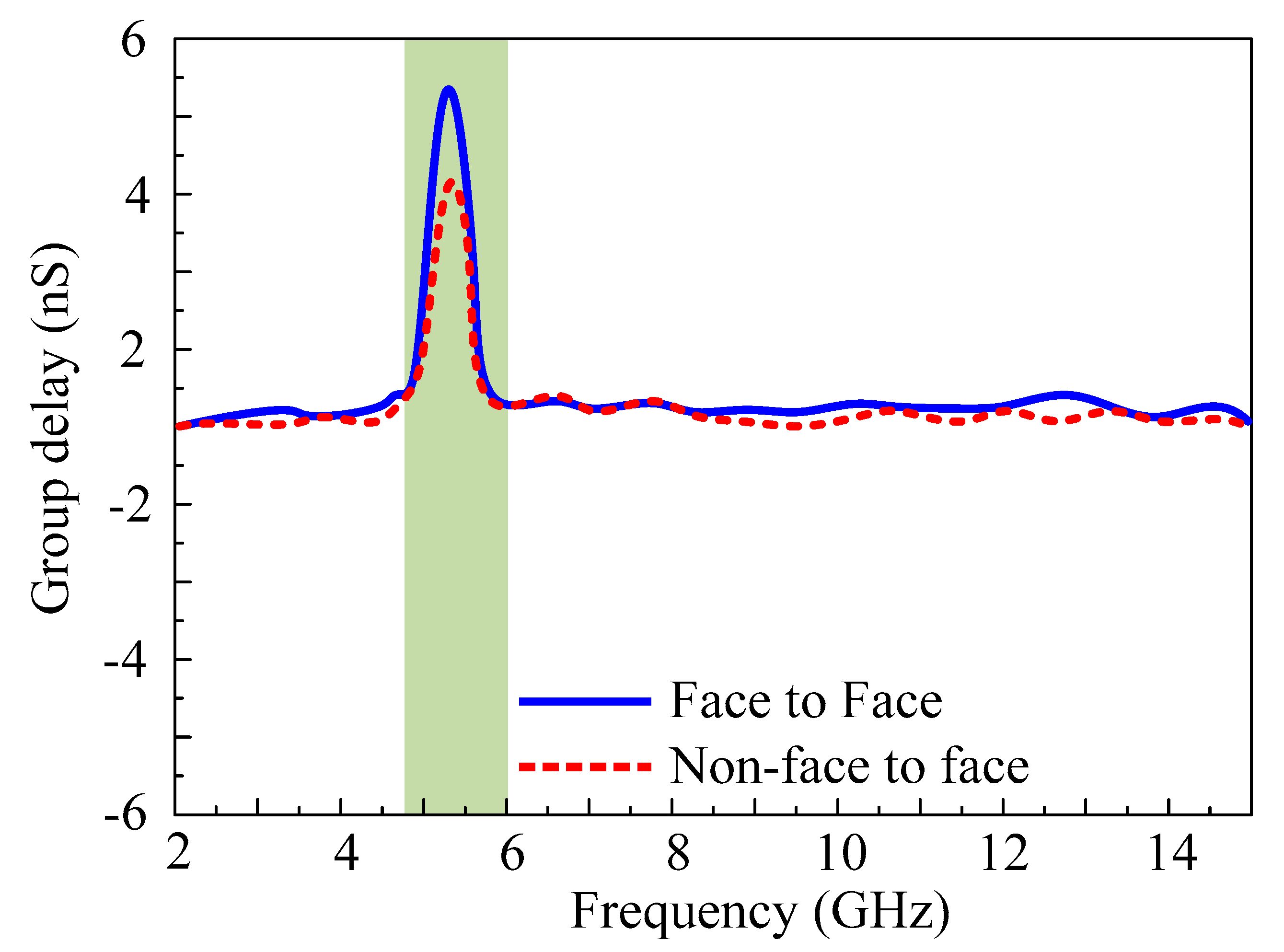
The radiation pattern of the proposed UWB antenna with a notch band is presented in Figure 8. The antenna offers a nearly omni-directional radiation pattern in the principal H-Plane for both resonating frequencies of 3.5 GHz and 6.5 GHz. On the other hand, for E-Plane, a dipole-like bidirectional radiation pattern was observed for 3.5 GHz, while a slightly tilted bidirectional radiation pattern was observed for 13 GHz, as depicted in Figure 8. In general, a strong agreement between simulated and measured results was observed for both resonating frequencies. It is worth noting that the antenna offers stable radiation patterns at all resonating frequencies, ensuring its wideband operation.

3.6. Group Delay

Group delay may be used to characterize the degree of distortion in the UWB antenna. In a UWB system, non-uniformity in group delay is desirable [31]. However, keeping the various losses with a small amount of non-uniformity is acceptable. Thus, two identical antennas are placed face-to-face and non-face-to-face at 30 cm to generate a far-field scenario. The group delay of the proposed notch band UWB is illustrated in Figure 9, where, except for the notch band, the group delay is entirely consistent. Except for the notch bands where the value is higher than >4 ns, the group delay varies less than 1 ns for the operational frequency range. Based on these results, the proposed antenna can be utilized for the UWB system, and there will be no distortion between the transmitting and receiving antennas.

4. Comparison with State-of-the-Art UWB Antennas

Table 1 summarizes the proposed antenna’s performance and its comparison with related work presented in the literature in recent years. It can be observed that the presented work offers a compact size as compared to all of the compared literature. The work reported in [15,17] offered dual-notch characteristics, but their size is twice as big as the proposed work. In addition, Refs. [17,18] offer a bit high peak gain value, but they suffer from structural complexity, along with the narrowband and big size as compared to the presented work. A semicircular-shaped printed antenna with two notch bands ranging from 3.3–4.2 GHz and 6.6–7.6 GHz was proposed in [19]. The lower notch band was realized using a modified dumbbell-shaped slot etched from the radiator, while the upper notch band was attained by employing a two-pair of capacitors, along with L-shaped slots carved from the ground plane. The antenna covers the complete UWB spectrum allocated globally. However, two pairs of capacitors along with narrow slots increase the structural complexity, while the physically large size of the antenna limits its applications for compact devices. In [20], a jug-shaped CPW antenna was presented. The antenna was fabricated on cheap FR4 substrate. However, the antenna does not offer any band rejection and may suffer from interference with WLAN spectrum. In [21], an EBG-backed monopole patch was presented. The antenna offers good notching characteristics. However, the antenna has a structurally large width of 25 mm. In [22], a metamaterial-backed monopole patch was presented, which offers a high gain. Although the presented design is a good candidate for high gain applications, the antenna offers no band-notched characteristics or interference rejection. Furthermore, an octagonal star-like monopole patch was presented in [23]. The antenna offers a fractional bandwidth of 120 percent. However, the antenna covers an area of 1275 mm2, which is geometrically larger than the presented antenna in this manuscript. In [24], a unique geometry of an antenna was presented, offering a bandwidth of 3.581–14.1 GHz. The antenna has a peak moderate gain of 3.2 dBi. This antenna does not offer any band rejection capability and may not be suitable for applications where low interference is a vital requirement. In [25], a planer stub-loaded patch was presented. The antenna offers dual band-notched characteristics. However, the presented design is about 20% structurally larger than the presented design. Based upon the above-mentioned discussion, the proposed UWB antenna with WLAN notch band overperforms all the related work by offering a compact size, wideband, comparable peak gain, and low structural complexity.

5. Conclusions

A CPW-fed antenna with compact dimensions of 15 mm × 10 mm × 0.254 mm for WLAN notch band UWB application was presented. The antenna consists of simple geometry with a modified rectangular shaped radiator loaded with a Y-shaped radiator, improving impedance bandwidth ranges 3–14.55 GHz. Hereafter, an additional stub was loaded to achieve WLAN band rejection capability. The proposed antenna offers key features of compact dimensions, wide bandwidth, and moderate gain. This UWB antenna also has band rejection at 4.59–5.82 GHz, thereby reducing the interference with the WLAN band. The specific notched band channel is the most congested part of the WLAN band spectrum 4.9 GHz (802.11j) and 5 GHz (802.11a/h/j) from channel 7 to channel 161. This spectrum is attenuated for reducing the interference with the UWB spectrum. The antenna offers a stable radiation pattern with a gain of more than 2 dBi in the pass band, while for the notch band, a minimum gain of –3.9 dB was observed. The measurement results of the fabricated antenna are well-matched to the simulation results. Moreover, the presented antenna overperforms the literature work by offering a compact size, having a notched band, a simple geometrical configuration, a moderate gain, and an ultra-wide impedance bandwidth. Therefore, the presented antenna is a worthy candidate for utilization in UWB applications where WLAN band rejection is a vital requirement for operation.

Author Contributions

Conceptualization, methodology, software, validation, and formal analysis, S.N.R.R. and N.H.; investigation, resources and data curation, D.C., S.G.P. and N.K.; writing—original draft preparation, S.N.R.R. and W.A.A.; writing—review and editing, D.C., N.H., S.G.P. and N.K.; supervision, project administration and funding acquisition, N.K. All authors have read and agreed to the published version of the manuscript.

Funding

This work was supported by the Institute of Information & Communications Technology Planning & Evaluation (IITP) grant funded by the Korean government (MSIT) (No. 2022-0-01031, Development of measured EMF big data analysis and management platform).

Institutional Review Board Statement

Not applicable.

Informed Consent Statement

Not applicable.

Data Availability Statement

Not applicable.

Conflicts of Interest

The authors declare no conflict of interest.

References

  1. Win, M.Z.; Dardari, D.; Molisch, A.F.; Wiesbeck, W.; Zhang, W.J. History and applications of UWB. Proc. IEEE 2009, 97, 198–204. [Google Scholar] [CrossRef]
  2. Kumar, O.P.; Kumar, P.; Ali, T.; Kumar, P.; Vincent, S. Ultrawideband antennas: Growth and evolution. Micromachines 2021, 13, 60. [Google Scholar] [CrossRef]
  3. Abbas, A.; Hussain, N.; Sufian, M.A.; Jung, J.; Park, S.M.; Kim, N. Isolation and gain improvement of a rectangular notch UWB-MIMO antenna. Sensors 2022, 22, 1460. [Google Scholar] [CrossRef] [PubMed]
  4. Khan, M.S.; Naqvi, S.A.; Iftikhar, A.; Asif, S.M.; Fida, A.; Shubair, R.M. A WLAN band-notched compact four element UWB MIMO antenna. Int. J. RF Microw. Comput. Aided Eng. 2020, 30, 22282. [Google Scholar] [CrossRef]
  5. Perli, B.R.; Avula, M.R. Design of wideband elliptical ring monopole antenna using characteristic mode analysis. J. Electromagn. Eng. Sci. 2021, 21, 299–306. [Google Scholar] [CrossRef]
  6. Yeom, I.; Jung, Y.B.; Jung, C.W. Wide and dual-band MIMO antenna with omnidirectional and directional radiation patterns for indoor access points. J. Electromag Eng. Sci. 2019, 19, 20–30. [Google Scholar] [CrossRef]
  7. Tangwachirapan, S.; Thaiwirot, W.; Akkaraekthalin, P. Design and analysis of antipodal vivaldi antennas for breast cancer detection. Comput. Mater. Contin. 2022, 73, 411–431. [Google Scholar]
  8. Al-Gburi, A.J.A.; Ibrahim, I.B.M.; Zakaria, Z.; Ahmad, B.H.; Shairi, N.A.B.; Zeain, M.Y. High gain of uwb planar antenna utilising FSS reflector for UWB applications. Comput. Mater. Contin. 2022, 70, 1419–1436. [Google Scholar]
  9. Jan, N.A.; Kiani, S.H.; Muhammad, F.; Sehrai, D.A.; Iqbal, A.; Tufail, M.; Kim, S. V-shaped monopole antenna with chichena itzia inspired defected ground structure for UWB applications. Comput. Mater. Contin. 2020, 65, 19–32. [Google Scholar]
  10. Jan, N.A.; Kiani, S.H.; Sehrai, D.A.; Anjum, M.R.; Iqbal, A.; Abdullah, M.; Kim, S. Design of a compact monopole antenna for UWB applications. Comput. Mater. Contin. 2021, 66, 35–44. [Google Scholar]
  11. Awan, W.A.; Choi, D.M.; Hussain, N.; Elfergani, I.; Park, S.G.; Kim, N. A frequency selective surface loaded UWB antenna for high gain applications. Comput. Mater. Contin. 2022, 73, 6169–6180. [Google Scholar]
  12. Al-Gburi, A.J.A.; Zakaria, Z.; Palandoken, M.; Ibrahim, I.M.; Althuwayb, A.A.; Ahmad, S.; Al-barwi, S.S. Super compact UWB monopole antenna for small IoT devices. Comput. Mater. Contin. 2022, 73, 2785–2799. [Google Scholar]
  13. Prasad, A.; Verma, S.S.; Dahiya, P.; Kumar, A. A case study on the monitor mode passive capturing of WLAN packets in an on-the-move setup. IEEE Access. 2021, 9, 152408–152420. [Google Scholar] [CrossRef]
  14. Brunner, H.; Stocker, M.; Schuh, M.; Schub, M.; Boano, C.A.; Romer, K. Understanding and mitigating the impact of wi-fi 6e interference on Ultra-Wideband Communications and ranging. In Proceedings of the 2022 21st ACM/IEEE International Conference on Information Processing in Sensor Networks (IPSN), Milano, Italy, 4–6 May 2022; pp. 92–104. [Google Scholar]
  15. Ramakrishna, C.; Kumar, G.S.; Reddy, P.C.S. Quadruple band-notched compact monopole UWB antenna for wireless applications. J. Electromag Eng. Sci. 2021, 21, 406–416. [Google Scholar] [CrossRef]
  16. Ojaroudi, M.; Ojaroudi, N. Ultra-wideband small rectangular slot antenna with variable band-stop function. IEEE Trans. Antennas Propag. 2013, 62, 490–494. [Google Scholar] [CrossRef]
  17. Jin, Y.; Tak, J.; Choi, J. Quadruple band-notched trapezoid UWB antenna with reduced gains in notch bands. J. Electromag Eng. Sci. 2016, 16, 35–43. [Google Scholar] [CrossRef]
  18. Lee, C.H.; Wu, J.H.; Hsu, C.I.G.; Chan, H.L.; Chen, H.H. Balanced band-notched UWB filtering circular patch antenna with common-mode suppression. IEEE Antennas Wirel. Propag. Lett. 2017, 16, 2812–2815. [Google Scholar] [CrossRef]
  19. Haider, A.; Rahman, M.; Ahmad, H.; Jahromi, M.N.; Niaz, M.T.; Kim, H.S. Frequency-agile WLAN notch UWB antenna for URLLC applications. Comput. Mater. Contin. 2021, 67, 2243–2254. [Google Scholar] [CrossRef]
  20. Ahmad, S.; Ijaz, U.; Naseer, S.; Ghaffar, A.; Qasim, M.A.; Abrar, F.; Parchin, N.O.; See, C.H.; Abd-Alhameed, R. A jug-shaped CPW-fed ultra-wideband printed monopole antenna for wireless communications networks. Appl. Sci. 2022, 12, 821. [Google Scholar] [CrossRef]
  21. Abbas, A.; Hussain, N.; Jeong, M.-J.; Park, J.; Shin, K.S.; Kim, T.; Kim, N. A Rectangular Notch-Band UWB Antenna with Controllable Notched Bandwidth and Centre Frequency. Sensors 2020, 20, 777. [Google Scholar] [CrossRef] [Green Version]
  22. Al-Bawri, S.S.; Hwang Goh, H.; Islam, M.S.; Wong, H.Y.; Jamlos, M.F.; Narbudowicz, A.; Jusoh, M.; Sabapathy, T.; Khan, R.; Islam, M.T. Compact ultra-wideband monopole antenna loaded with metamaterial. Sensors 2020, 20, 796. [Google Scholar] [CrossRef] [PubMed] [Green Version]
  23. Lakrit, S.; Das, S.; Madhav, B.T.P.; Babu, K.V. An octagonal star shaped flexible UWB antenna with band-notched characteristics for WLAN applications. J. Instrum. 2020, 15, P02021. [Google Scholar] [CrossRef]
  24. Jameel, M.S.; Mezaal, Y.S.; Atilla, D.C. Miniaturized coplanar waveguide-fed UWB Antenna for wireless applications. Symmetry 2023, 15, 633. [Google Scholar] [CrossRef]
  25. Kumar, P.; Ali, T.; MM, M.P. Characteristic mode analysis-based compact dual band-notched UWB MIMO antenna loaded with neutralization Line. Micromachines 2022, 13, 1599. [Google Scholar] [CrossRef] [PubMed]
  26. Jaglan, N.; Gupta, S.D.; Kanaujia, B.K.; Srivastava, S. Band notched UWB circular monopole antenna with inductance enhanced modified mushroom EBG structures. Wirel. Netw. 2018, 24, 383–393. [Google Scholar] [CrossRef]
  27. Xu, H.; Xu, K.D.; Nie, W.; Liu, Y.H. A coplanar waveguide fed UWB antenna using embedded E-shaped structure with WLAN band-rejection. Frequenz 2018, 72, 325–332. [Google Scholar] [CrossRef] [Green Version]
  28. Aitbar, I.; Shoaib, N.; Alomainy, A.; Quddious, A.; Nikolaou, S.; Imran, M.A.; Abbasi, Q.H. AMC integrated multilayer wearable antenna for multiband WBAN applications. Comput. Mater. Contin. 2022, 71, 3227–3241. [Google Scholar] [CrossRef]
  29. Kumar, O.P.; Kumar, P.; Ali, T. A compact dual-band notched UWB antenna for wireless applications. Micromachines 2021, 13, 12. [Google Scholar] [CrossRef]
  30. Awan, W.A.; Hussain, N.; Kim, S.; Kim, N. A frequency-reconfigurable filtenna for GSM, 4G-LTE, ISM, and 5G Sub-6 GHz band applications. Sensors 2022, 22, 5558. [Google Scholar] [CrossRef]
  31. Iqbal, A.; Smida, A.; Mallat, N.K.; Islam, M.T.; Kim, S. A compact UWB antenna with independently controllable notch bands. Sensors 2019, 19, 1411. [Google Scholar] [CrossRef] [Green Version]
  32. Mukherjee, K.; Mukhopadhyay, S.; Roy, S. Design of a wideband Y-shaped antenna for the application in IoT and 5G communication. Int. J. Commun. Syst. 2022, 35, 5021. [Google Scholar] [CrossRef]
  33. Jeong, M.J.; Hussain, N.; Bong, H.U.; Park, J.W.; Shin, K.S.; Lee, S.W.; Rhee, S.Y.; Kim, N. Ultrawideband microstrip patch antenna with quadruple band notch characteristic using negative permittivity unit cells. Microw. Opt. Technol. Lett. 2020, 62, 816–824. [Google Scholar] [CrossRef]
  34. Mekki, K.; Necibi, O.; Lakhdhar, S.; Gharsallah, A. A UHF/UWB monopole antenna design process integrated in an RFID reader board. J. Electromag Eng. Sci. 2022, 22, 479–487. [Google Scholar] [CrossRef]
Figure 1. The geometry of the proposed WLAN Notch UWB antenna. (a) Top view, (b) side view.
Applsci 13 04271 g001
Figure 2. Proposed antenna’s (a) various design steps. (b) |S11| responses.
Applsci 13 04271 g002
Figure 3. |S11| of the antenna for different values of (a) SW, (b) s, (c) CL.
Applsci 13 04271 g003
Figure 4. Proposed extended UWB antenna’s (a) prototype and (b) antenna under test.
Applsci 13 04271 g004
Figure 5. Measured and simulated |S11| of the proposed notch band extended UWB antenna.
Applsci 13 04271 g005
Figure 6. Simulated and measured gain of the proposed notch band extended UWB antenna.
Applsci 13 04271 g006
Figure 7. Current density of proposed notch band extended UWB antenna at various frequencies.
Applsci 13 04271 g007
Figure 8. The radiation pattern of proposed notch band extended UWB antenna at various frequencies.
Applsci 13 04271 g008
Figure 9. The group delay of the proposed notch band extended UWB antenna.
Applsci 13 04271 g009
Table 1. Performance comparison of the proposed antenna with existing UWB antennas in the literature.
Ref.Dimensions
o × λo × λo)
Frequency Range
(GHz)
Rejection Band
(GHz)
Peak Gain
(dBi)
Design Methodology
[15]0.3 × 0.31 × 0.022.9–14.53.1–3.6/4.9–6.1No. Info.Slot and SRR-loaded Antenna
[16]0.21 × 0.21 × 0.023.04–10.875.03–5.944.2Slot and SRR-loaded Antenna
[17]0.29 × 0.33 × 0.082.88–12.673.43–3.85/5.26–6.014.6Slot and SRR-loaded Antenna
[18]0.32 × 0.30 × 0.0052.95–10.755.01–6.195.2Band Pass Filter-loaded Antenna
[19]0.25 × 0.32 × 0.023.1–11.23.3–4.2/6.6–7.65.1Capacitor-loaded Patch
[20]0.255 × 0.222 × 0.023–11None4.1Jug-shaped Monopole Patch
[21]0.17 × 0.27 × 0.023.1–12.55–64.5EBG-backed Monopole Patch
[22]0.148 × 0.2263.08–14.1None4.54Metamaterial-backed Antenna
[23]0.44 × 0.32 × 0.083.25–135.7–6.26.7Octagonal Star-Like Patch
[24]0.32 × 0.3 × 0.023.581–14.1None3.2Slotted CPW-Fed Antenna
[25]0.24 × 0.31 × 0.013.4–11.94.5–5.3/7.2–93.9Stub-loaded Planer Patch
This Work0.11 × 0.19 × 0.0023–14.554.59–5.824.93Stub-loaded Printed Antenna
Disclaimer/Publisher’s Note: The statements, opinions and data contained in all publications are solely those of the individual author(s) and contributor(s) and not of MDPI and/or the editor(s). MDPI and/or the editor(s) disclaim responsibility for any injury to people or property resulting from any ideas, methods, instructions or products referred to in the content.

