Article

Research on the Energy Characteristics of a Transferred Arc Plasma-Chemical Reactor for Waste Treatment †

by
Rolandas Uscila
,
Viktorija Grigaitienė
*,
Vitas Valinčius
,
Romualdas Kėželis
,
Dovilė Gimžauskaitė
and
Žydrūnas Kavaliauskas
Plasma Processing Laboratory, Lithuanian Energy Institute, Breslaujos St. 3, LT-44403 Kaunas, Lithuania
*
Author to whom correspondence should be addressed.
This paper is an extended version of paper published in the international conference: 8th International Conference on Sustainable Solid Waste Management, Thessaloniki, Greece, 23–26 June 2021.
Appl. Sci. 2023, 13(7), 4221; https://doi.org/10.3390/app13074221
Submission received: 31 January 2023 / Revised: 22 March 2023 / Accepted: 24 March 2023 / Published: 27 March 2023
(This article belongs to the Section Applied Thermal Engineering)

Abstract

:

Featured Application

Plasma processing of waste; novel plasma torch development.

Abstract

This study has been performed to reveal the main characteristics of operating a direct current (DC) plasma-chemical reactor (PChR) designed for hazardous waste treatment. The PChR employs thermal plasma as the operating environment. The investigations presented in this paper were conducted to study the electrical and energy characteristics of the plasma torch and plasma-chemical reactor during the destruction of inorganic waste. The PChR is equipped with a plasma torch with a nominal capacity of 50 kW and a free-burning arc. The zone of heat release from the atmospheric pressure DC arc cathode and arc anode (melted waste) spot is combined with the area of chemical reactions. The plasma torch (PT) parameters vary in the range of arc current I = 120–180 A, arc voltage U = 250–280 V, arc length x = 0–100 mm, and gas flow rate G = 1–3 g/s at atmospheric pressure, using air as the plasma-forming gas. The experimental results confirmed that plasma technology has several advantages over conventional incineration, including higher temperatures, heat source independence from the waste being processed or additional fuel, and a shorter exposure time in the high-temperature area. It was determined that the arc current increases with increasing arc length. With increasing arc length, the initial part begins to operate in a turbulent regime. This study determines the dependence on the heat flux transferred by electrons to the anode on the arc current. The convective heat flux density distribution over the anode heating spot was measured and discussed.

1. Introduction

One of the most important issues in preserving the surrounding environment is the disposal and recycling of domestic and industry-generated waste. The processing of waste must be considered the essential link between the artificial technosphere, which generates the most significant part of the waste, including harmful and environmental [1,2]. However, until now, all broadly available waste management technologies have not satisfied modern requirements. For the sustainable management of natural resources and to reduce environmental pollution, it is necessary to seek new, environmentally friendly methods and technologies for storing, recycling, or recovering energy from all types of waste (industrial, household, or hazardous).
The technologies currently in use are insufficient for attaining the main objectives declared in the EU directives. In particular, waste containing harmful or toxic substances requires high temperatures for recycling. Thermal decomposition techniques are primarily used for this purpose. However, low-temperature pyrolysis or heat treatment (incineration) is unsuitable for decomposing such waste. At temperatures of 450–800 °C (pyrolysis) or up to 1000 °C (burning), new toxic compounds such as dioxins, furans, and other hazardous substances may form [3], which are much more harmful than the initial product. To fully counteract the effects of harmful substances on the environment and human health, it is necessary to recycle them at significantly higher temperatures, reaching 1100–1700 °C. At such temperatures, the molecules of the toxic compounds are broken into atoms, radicals, electrons, and positive ions, and simple harmless substances are formed with decreasing temperature. Thermal plasma technology is best suited for this purpose. Waste is usually destroyed using arc plasma generated by a plasma torch. The main advantage of plasma waste recycling (when compared to physiochemical or biological recycling) is its versatility, allowing for the decomposition of any kind of waste [4,5,6,7,8,9,10,11]. Therefore, waste processing technology using plasma energy sources was studied experimentally in the present work.
All hazardous waste decomposition facilities are subject to high-risk and special technical, occupational safety, and environmental requirements. They can only be guaranteed using modern scientific and technical knowledge and precision measuring equipment. The main requirement for a waste decontamination plant is not the only achievement of limited emissions of toxic substances after neutralization, which should not exceed permissible levels. Emissions must be minimized in all cases of the destruction process. This is possible when a processed substance is broken down into harmless compounds for humans and the environment. This study requires an experimental procedure to determine the necessary temperature, main and additional gas flow rates, and composition needed for chemical reactions (O2, H2, water vapor, etc.) to analyze the exhaust gas and solids formed and then start the industrial neutralization of the given material.
Currently, the destruction of hazardous substances with a melting point higher than 1400 °C is very complicated and expensive using traditional technologies. In many cases, arc plasma technologies are more economical and acceptable for ecological and environmental protection. Thermal plasma is an excellent tool that significantly accelerates all the processes involved in the processing and decomposition of materials. It is important for recycling or disposing materials with high melting points. Plasma treatment is a technology in which fundamental and applied science and manufacturing are strongly interconnected. The thermal properties of plasma, such as the very high temperature and the high concentration of energy in a small volume and the ability to be heated to the required temperature of any gas, allow for processes that are not possible at moderate temperatures at atmospheric pressure. The use of arc plasma generators (plasma torches) in the industry enables the realization of many processes, such as reducing metal oxides, the synthesis of nanoparticles of metals and materials with a very high melting point, and many others, without the use of additional chemical processing. This process can be realized using a unique plasma-chemical reactor (PChR) device. This technology is suitable for small or large-scale production runs, and the process can be fully automated.
This technology can also be used to decontaminate a variety of harmful and hazardous waste. High-temperatures and dense energy concentrations in a small volume completely break down harmful substances into their components and decompose them into environmentally friendly products. The technological circuit of this process is shown in a diagram in Figure 1. An electrical arc at atmospheric pressure usually appears as a constricted area of electrical and mechanical forces, which causes the plasma fluid to move away from the arc column. Plasma-chemical reactions occur in the reactive zone of an arc in the presence of a controlled amount of plasma-forming gas. The final product, consisting of a vitrified glass-like substance, is collected at the bottom of the reactor and is used as a raw material for a wide range of applications. The higher the temperatures reached by the arc, the more efficient the conversion of organic waste into light organics and primary elements [7,8,12,13].
When plasma activating energy is applied, it is possible to increase the rate of chemical reactions by hundreds of times and achieve stable, high average temperatures of 1800–2500 °C inside the PChR. However, developing new design equipment generating a plasma arc for the treatment of hazardous waste or waste with high melting temperatures (up to 1400 °C) is impossible without knowledge and understanding of the features of high-temperature processes occurring in the gas discharge chamber of the PT and the PChR.
The gases used as heat carriers differ significantly in their energy characteristics. Therefore, when selecting the forming plasma gas, it is necessary to consider the possibility of obtaining high enthalpy values, using this gas as a chemical reagent, and the inertness of the target products. In plasma-chemical reactors for material processing, a DC electric arc operating in an argon (Ar) atmosphere is typically used [11]. However, it is well known that, from an economic point of view, it is more beneficial to use high-enthalpy gases such as nitrogen, air, or hydrogen [10,11,14]. Plasma torches with DC electric arcs operating in an air or nitrogen atmosphere have been extensively studied [15,16,17]. However, the characteristics of the free-burning arc in the air or the nitrogen ambient, which are applicable to plasma-chemical reactors, have not been sufficiently studied. Therefore, studying arc plasma behavior in an air atmosphere is beneficial.
The efficiency, heat transfer characteristics, and interaction between a plasma jet and material in a PChR for waste destruction have been studied in many studies—for example [2,9,11]. However, the electric arc characteristics and the energy balance at the plasma torch anode were mainly investigated while working with an argon arc. A particular interest also appeared in the energy exchange between the plasma arc and the surface; the arc efficiency is higher when a plasma jet interacts with a flat surface. It is also well known that high-temperature argon gas has relatively low enthalpy and is a poor conductor of heat and electricity. Therefore, the use of a high-enthalpy molecular gas, such as air or nitrogen, for material processing using plasma technology is more advantageous [18,19]. In many papers, the authors solving fundamental energy production problems, environmental protection, public health, etc. have appropriately selected a plasma source. However, the application of plasma sources requires very complicated, expensive, and energy-receptive fundamental and applied investigations, which are necessary to create new and very effective PT. Sometimes, when plasma technology is investigated as a waste treatment tool, it is not easy to apply similarity theory or numerical simulation laws.
Modern waste recycling and disposal methods are based on high-technology processes of their gasification with the production of synthesis gas [14,20,21] or two-stage combustion using steam, gas, combined-cycle turbines, or gas engines to generate electricity [18,21,22,23,24]. This second high-temperature stage guarantees the complete neutralization of processed products from the formation of dioxins and furans. So, the emissions from modern power plants burning waste are several times lesser in terms of volume and harmfulness than emissions from gas- or coal-fired thermal power plants.
The high thermal energy density of the electric arc allows for reaching high-temperature flows in the plasma-chemical reactor and creating an environment of almost any chemical composition. The technology based on high-temperature plasma-chemical reaction until complete decomposition of recyclable products using arc plasma is considered to be implemented recently. Novel plasma-chemical reactors with liquid-metal electrodes that avoid erosion are the subject of recent research [25]. The main advantages of such reactors are the following:
versatility in the variety of processed waste and raw materials;
the absence of dioxins in final products;
the ability to use steam as plasma-forming gas instead of expensive inert gas;
there are no restrictions on the resource of electrodes.
Therefore, PT characteristics should be examined separately for different gaseous atmospheres. The careful study of PT parameters employing the electro-dynamical electric arc theory and solving problems of plasma flow diagnostics allowed for the design of a powerful plasma arc generator that operates stably for a long time in a reactive gas ambient.

2. Materials and Methods

2.1. Plasma-Chemical Method for Waste Processing

The experiments presented in this paper were performed in a PChR designed for hazardous waste treatment in the reacting arc zone. Environmental laws and strict government regulations limit the substantial destruction of hazardous substances, so less harmful materials of a similar composition were chosen for this research. So, only slightly toxic materials were selected, mixed with clay, and processed.
A DC electric arc was operated between the plasma torch cathode and graphite bath (Figure 2) located at the bottom of the PChR. PT could be moved along the axis of the arc, and thus, its length was changed. The parameters of the PT varied with the following limits: arc current I = 120 to 180 A, arc voltage U = 250 to 300 V, PT power reaches up to P = 50 kW, arc length x varies from 0 to 100 mm, and airflow rate G = 1 to 3 g/s. The experiments were conducted under atmospheric pressure. An experimental facility with a plasma source, auxiliaries, and supporting equipment is described in more detail in [26].
The operating conditions and regimes of the PT remained constant during all experiments. The capacity of PT, the total mass flow rate of air plasma, and the cooling water flow rate Gv and temperature were measured using electronic measuring devices. Experimental data were obtained using analytical equipment. During plasma measurements, the signals of primary transducers (thermocouples, pressure sensors, electric probe) were measured and recorded employing multimeters, amper voltmeters, and micro manometers. The measurement, regulation, and control of the arc current and voltage of the plasma sources were carried out by the amperemeter and voltmeter readings. A calibrated shunt with an accuracy class of 0.01 was used to measure the arc current. The data collection system “Multimeter 2700” by KEITHLEY (USA) was used to register the signals of the temperature and pressure transducers. The plasma characteristics were calculated from these data.
In our case, technological processes occur in the thermal plasma torch and its generated high-temperature ambient, which flows out of the reactor nozzle. In fact, the work of the plasma torch is related to physical phenomena of an electromagnetic, thermal, and dynamic nature. Semi-empirical methods are used for the research to generalize the integrated characteristics of the plasma source. They make it possible to experimentally determine the criterion dependencies of plasma generators of similar geometric sizes.
The analysis of the similarity of physical processes in PG made it possible to develop standard methods for their design. Despite the complexity of the process, the number of parameters determining the PG mode is small next to the number of primary criteria. Thus, non-dimensional equations are necessary for the qualitative description of physical PT processes, so in this research, the electrical characteristics were determined at a constant current and atmospheric pressure. Regarding the generalization of voltage-current characteristics, the theory of the similarity of electrical processes has been used, and a special study was conducted and described [17].
The physical and thermal properties of air and nitrogen gas were determined using [27].

2.2. Plasma-Chemical Reactor and Plasma Source

The plasma treatment process was investigated in a volume reactor consisting of a metal case lined inside with a layer of refractory and heat-insulating materials, as described in [17,26]. Such a reactor is suitable for the destruction of extremely hazardous solid substances owing to the relatively long exposure time of the material in a high-temperature zone. The authors also designed a novel experimental plasma volume reactor to create a steady non-transferred plasma environment (Figure 2). The shield of this reactor is made of metal with a high-temperature ceramic lining. It consists of a flat graphite plate used as the anode and a cooling PT that works as a cathode. A cooling graphite flat plate was mounted with thermal sensors and thermocouples with an external diameter of 4 mm. The reactor’s body and graphite plate were then grounded. During waste processing, a PT generates the high-temperature flow necessary for destroying the chemical bonds in hazardous materials [13,18]. The highly intense energy flux initiated by PT is powerful enough to degrade or detoxify hazardous waste into atoms, molecules, and radicals.
Combined heat and mass transfer occur in the electric arc plasma generator owing to the interaction of the arc, gas, and walls. When the electric current flows into an ionized gas, the electric arc energy transforms into heat, which is transferred to the flow, channel walls, and electrodes. However, only the energy transferred to the flow was beneficial.
Generally, the arc length depends on the construction of the PT and processes occurring in the reaction chamber. It is most affected by the phenomenon of electric discharge, called arc bypass, which can be significant (discharge occurs between the arc column and the anode wall) or negligible (discharge occurs between individual parts of the arc). During high-amplitude shunting, the parameters of the electric arc and, simultaneously, the gas flow change and instability increase. However, in the presented reactor, the arc length is regulated by changing the distance between the plasma source and graphite plate, that is, between the anode and cathode. It can be achieved by employing a specific mechanical device.
The gas entering the reaction chamber flows inside the PT into the arc, and the gas temperature increases, which increases the thickness of the positive column of the arc in the direction of gas flow. During the intensive cooling of the PChR, the arc cannot reach its wall, so there is always a layer of electrically non-conductive gas between the wall and the arc. When broken, it undergoes bypass processes that determine the length of the arc. The current density in the arc was 104–107 A/m2, that in the anterior part of the arc was 108–1010 A/m2, and that in the anodic part was 106–109 A/m2. The length of the pre-cathodic zone of the atmospheric pressure plasma arc was approximately 10−6 m, which is equal to several particle-free path lengths. It indicates that the thermoelectric emission of electrons from the cathode to the gas and the PChR wall is possible.
The PT hafnium cathode and copper body were intensively cooled using water (Figure 3). The sensors were electrically insulated from the anode by fluorine-plastic liners and ceramic backfilling. The anode moved across the arc; thus, the sensors measured the heat flux distribution along the spot of the arc. The values of the PT parameters used in the experiments are listed in Table 1.
The heat generated by the PT brings the waste material to temperatures that are sufficient to melt and destroy it entirely. An experimental plasma torch was constructed to determine the energy transfer peculiarities from the free electric arc to waste. A plasma torch used for waste utilization can operate with different gases such as air, nitrogen, or water vapor. The choice is generally determined by the composition of the decontaminated waste, the type of plasma torch, and the final product and economic factors to be obtained. Standard gas supply and regulation fittings were used to supply gas into the plasma torch and plasma-chemical reactor. Recently, it has become possible to use the products of reactor combustion as plasma-forming gases. If such gas is fed into the PT, it must be cleaned regarding dust, moisture, or residuals of the final product.
The experimental reactor casing is made of steel, and the casing length is 0.25 m, with an interior diameter of 0.28 m. The PChR has a jacket for cooling and an opening for probes used for exhaust gas composition analysis and velocity and temperature measurements. The inner surface of the reactor casing was covered with a high-temperature resistant liner to reduce heat loss. It consisted of two layers. The first layer (to the metal) was made of 5 mm-thick asbestos. The second layer, with a 3.7 mm thickness, was a ceramic consisting of a mixture of aluminum and zirconium oxides. The inside diameter of the channel was 0.24 m. The cover of the reactor casing was also water-cooled. The plasma torch is inserted into the reactor’s opening, and the housing is insulated from the reactor’s container.
PChR also has an opening for the input of recyclable materials (see Figure 2). It is also equipped with a plasma torch positioning device. The graphite plates at the bottom of the reactor were used as an anode. The melt formed during the experiments was released through a plate hole. The device was based on a high-temperature-resistant alumina bricks layer (Figure 2).
During the experiments, the power of the plasma torch, its temperature, gas flow rate, and cooling-water flow rate were measured. The amount of recycled material was also calculated. The plasma torch power was determined by measuring the electric arc voltage and current. The experimental facility power supply system, air supply system, cooling system, data collection system, and measuring system have been described in detail in previous work [13].
Zeolite granules and dried clay were used to determine the electrical and energy characteristics of PChR for waste processing in the future. After use in the chemical industry, waste zeolite granules and clay were processed in PChR as contaminated soil. The gas temperature distribution in the plasma-chemical reactor and the electrical potential were measured during the experiments. For this objective, a special probe was designed and constructed. The outflow gas temperature from the plasma-chemical reactor was measured using a set of chromel-alumel thermocouples.

3. Results and Discussion

The electrical characteristics of the plasma torch, also known as voltage-current characteristics (VCC), characterize the dependence of the electrical arc current and voltage on the geometry of the discharge chamber used for cathode protection and the main plasma working gas, pressure, temperature, and power supply. These parameters characterize the linear plasma torch VCC, as described in [12,13]. When using a plasma torch for waste treatment, parameters such as the plasma-chemical reactor geometry, the composition of the recycled materials, the recycling and chemical properties, and the flow rate of gases emitted during the decontamination process are evaluated. The VCC also depends on the characteristics of the plasma torch-powered source.

3.1. Characteristics of DC Arc

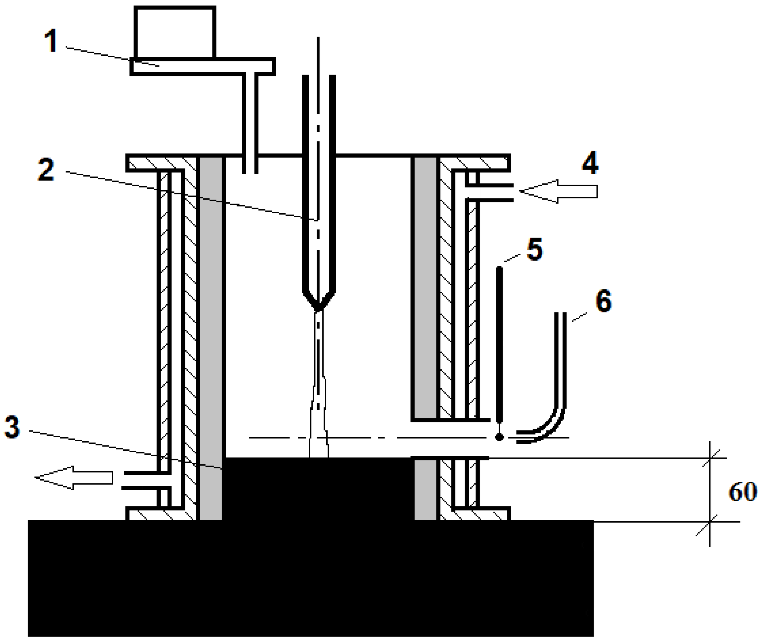
As previously mentioned, a linear plasma torch (Figure 3) with a hafnium cathode was designed and constructed for experimental waste decontamination. Insulated from the plasma-chemical reactor, the casing shell also served as an intermediate electrode for igniting an arc. The electric arc in the plasma-chemical reactor was ignited by lowering the plasma torch so that the gap between the anode and the plasma torch was 3–5 mm. A high-voltage discharge ignites the so-called initial arc between the cathode and intermediate electrode. The low-power plasma jet that reaches the anode ignites the main electric arc. When the electric arc was ignited, the plasma torch was raised; then, the expected power of the plasma torch was obtained. 
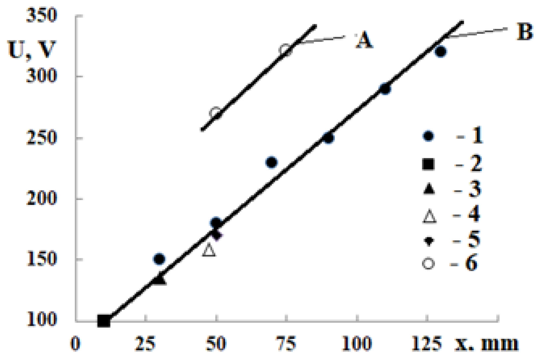
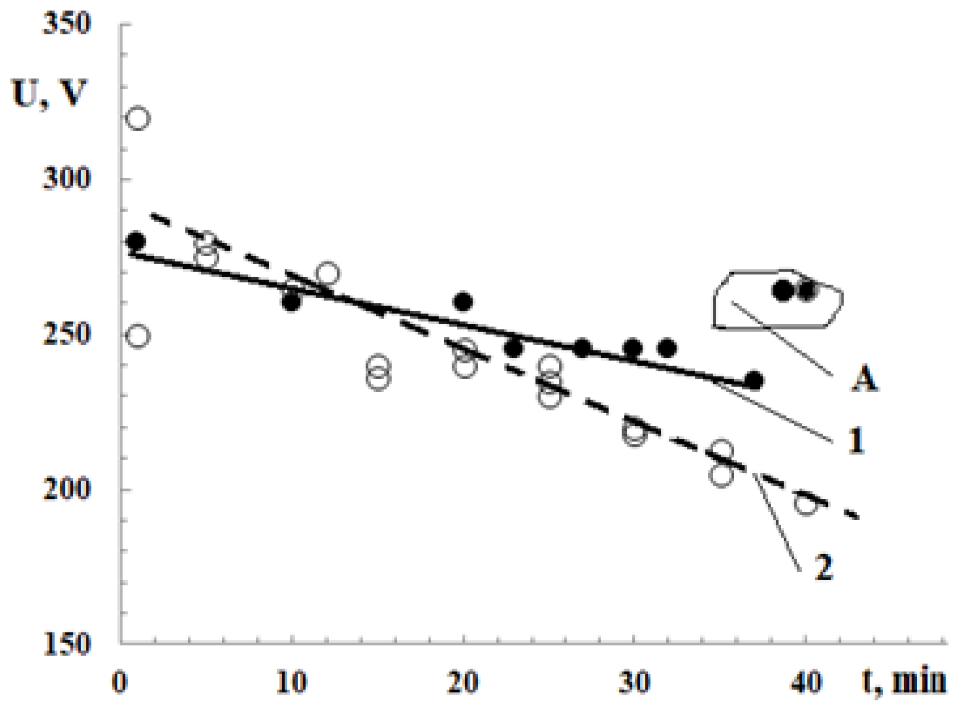
Figure 4 shows the dependence of the voltage of the electric arc on its length (between the cathode and a graphite anode). In our case, the voltage drop per unit length of the arc column has a constant value. Therefore, the arc voltage’s dependence on the arc length is linear (Figure 4). The stability of the steady arc is determined by the relationship between the current and voltage.
The electric arc in the plasma-chemical reactor is considered to be free, although the walls slightly limit its development in the reactor’s space. However, the shielding gas does not limit the arc; the gas flow only stabilizes it. Air, as plasma-forming gas in the PT, is supplied from the cathode side for its protection, while air consumption does not influence the arc characteristics. In the presence of internal energy sources, heat flux to the reactor walls can be determined according to [16].
Under the influence of electromagnetic forces, a plasma-forming gas stream flows from the cathode toward the anode [17]. Because the anode is a surface of solid processing material, the gas jets of the evaporated material outflow from it, and the vapor jet is thicker than the cathode gas stream but much shorter. These two jets collided to form a plasma plume. In such a case, the arc operation is unstable.
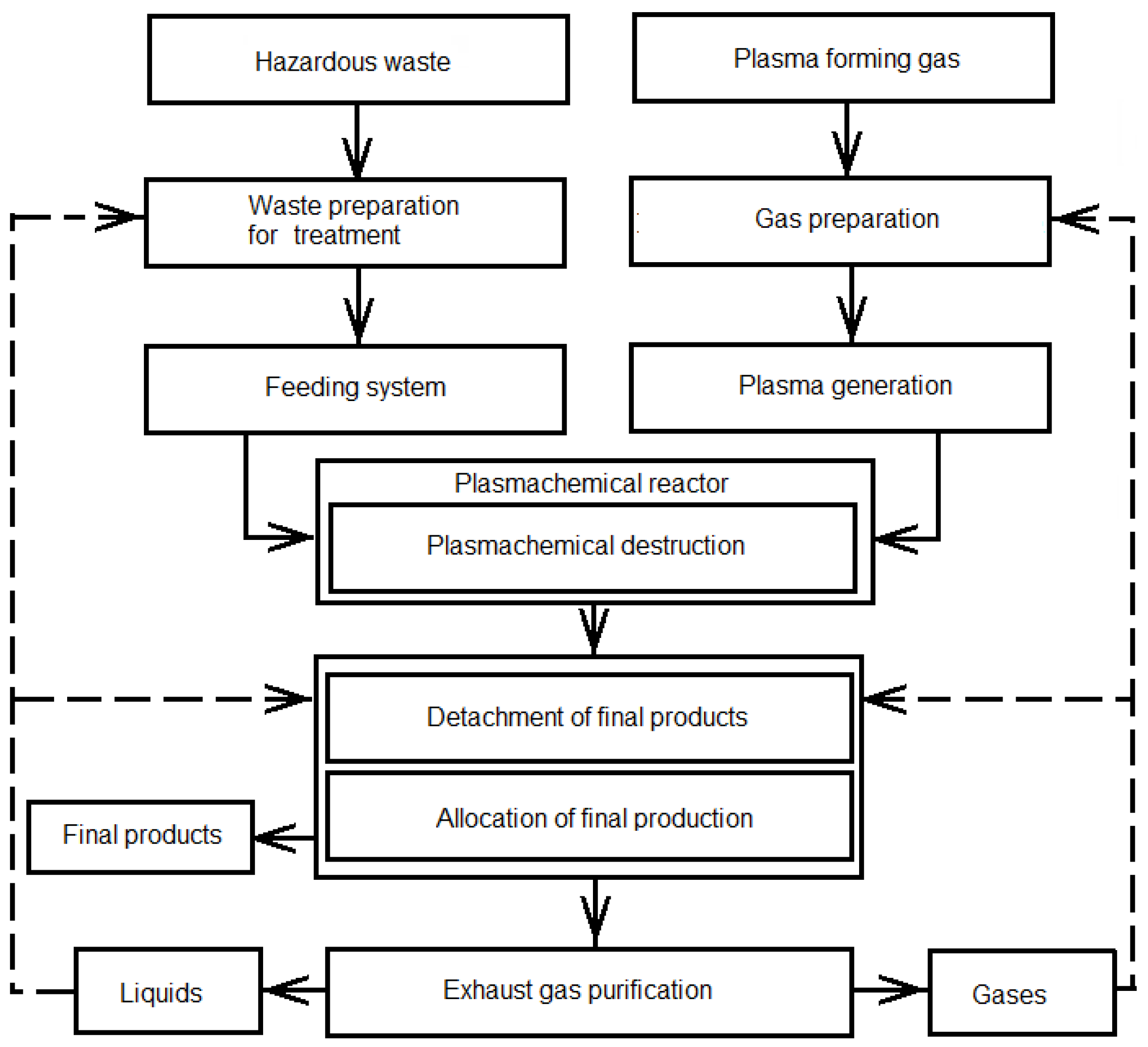
When the surface of the melted material serves as the anode (Figure 2), a plasma plume is not formed because the anode steam jet does not have a strict direction. The electric arc operates in a more stable mode than that in the case of a solid anode.
With such a PT, it is possible to generate highly concentrated heat fluxes using air as a plasma-forming gas for hazardous waste utilization. By contacting the raw material with plasma in the PChR, a high local heat flux destroys it; all organic matter and its harmful compounds are destroyed and removed from the reactor in the form of gas. Waste, an inert material with a high melting point, such as various aluminosilicates, carbides, nitrides, and inorganic metal oxides with melting points of up to 2500 K, become a melt. The melting process involves the interaction of a highly concentrated local heat flux generated by a plasma torch with inert materials. Consequently, they melted and accumulated on the graphite anode. Owing to its high melt temperature, it is an electrically conductive material; when the melt overlays the anode, the electric arc continues to burn between the anode and melt layer, maintaining its high temperature owing to its ohmic resistance. In the PChR, the VCC of a free arc in an air atmosphere with an anode as melted waste was measured at different arc lengths (Figure 4). It was observed that, up to x = 150 mm, the arc voltage was almost independent of the arc current. This implies that, by increasing the arc length, the arc voltage changes depending on the plasma torch position concerning the anode (the arc length was manually altered by changing the electrode position). The electric arc voltage also depends on the processes occurring in the reaction chamber.
The electrical arc at atmospheric pressure appeared as a constricted area of electrical and mechanical forces, which caused plasma fluid to move away from the arc column. In this case, the plasma fluid is replaced by cold gases injected into the arc-reacting zone from the outside. The processes in the electric arc zone include turbulent mixing, chemical reactions, ionization processes, the transfer of electric energy to conducting particles, and the transformation of electric power into thermal energy and radiation. The investigation of the influence of these factors requires the simultaneous characterization of the arc and its characteristics in association with gas and plasma flow parameters.
Depending on the values of the electric current strength, gas flow rate, channel diameter, and pressure, the VCC of the plasma torch falls: with an increase in the current strength, the arc burning voltage decreases. Obtaining descending characteristics, an intensive cooling of the anode (in our case, melt) is required, which is realized at a high flow rate or when the arc is compressed by the walls of the arc chamber, which is possible with intensive cooling of the PChR walls. In the presented PChR design, dropping VCC is always obtained.
The physics of the descending VCC of the arc formation in the plasma torch can be represented as follows. A so-called free-burning arc is realized when the arc burns in an unlimited space between the two electrodes. The length, diameter, and configuration of such an arc depend on gas properties and the electric current strength. In particular, with increasing current, the diameter of the arc loosely increased because there were no limiting factors in the radial direction. Because the dependence of the arc voltage on its length is linear, the arc’s diameter will also be almost constant if it is not affected by any external factors, such as cross-flow or artificial rotation of the arc spot. In the presented plasma torch, the arc burns in a volume between the chamber walls and the flow of the plasma-forming gas. Such an arc is nonstabilized, and its diameter depends on the geometry of the discharge chamber, current strength, gas flow rate through the plasma torch, and gas composition inside the reactor. The anode end diameter is determined by measuring the diameter of the cavity formed on the graphite plate during the plasma processing. Such a study was carried out in a DC electric arc volume reactor. At very low gas flow rates, the influence of flow on the arc diameter can be significant. It was found that the spot’s area exceeded the area of the cavity on the anode by approximately 1.5 times. In such a case, the arc appears as “diffused”, and its stability by the wall is impossible and takes a free form.
The arc narrows in the near-cathode area, and the arc properties differ significantly from those of the near-anode region. Therefore, by analyzing the geometry of the arc, it is possible to distinguish the physical processes occurring at the cathode, anode, and space between them. Three characteristic regions (a central zone or arc column, the anode, and the cathode) were visible from the potential distribution along the arc axis. Directly toward the cathode, the region of the cathodic potential drop occurs, which is characterized by the strength of the electric field. The region of the anode (melt) also exhibited a potential drop. The length of this region is several mean free paths of electrons. The potential drop was also insignificant (only a few volts).
The near-electrode regions are connected by a conductive channel that is homogeneous in structure, which is called the positive column of an electric arc. Unlike other parts of the arc discharge, which have specific dimensions depending on the nature of the gas, its pressure, and the strength of the discharge current, the length of the positive column is determined by the distance between the electrodes; that is, it can vary over a very wide range. For the presented type of electrical discharge (free-burning arc), the positive column was characterized by a relatively low and approximately constant electric field strength along the discharge length.
The relationship between the steady-state values of the arc voltage and current for a constant x is called static VCC. To determine the reasons for the significant difference in the VCC characteristics at arc length x < 125 mm, the dependence of the arc voltage on time was investigated (Figure 5). It was found that the arc burns in laminar flow mode; however, it looks like a rod. At I = 150 A, the laminar arc reached a distance of x = 170 mm, and noise and crackling appeared due to arc fluctuations. In order to determine the reasons for a difference in the voltage–current characteristics in laminar and turbulent modes, the dependence of arc voltage on arc length was investigated. It was found that a short arc burns in a laminar mode, whereas it looks like a rod and burns noiselessly. For example, at I = 150 A, the laminar arc reaches the distance of x = 170 mm. At x > 170 mm, noise and crackling appear due to the arc fluctuations, and a part of the arc operates in a turbulent mode and becomes a multifilament, as presented in [17]. The turbulent regime was also characterized by higher values of arc voltage.
The steady arc in the reactor, as an energy consumer, and the arc power source, such as the transformer and rectifier, form an interconnected energy system. There exist two modes of operation of this system: (1) static, when the values of voltage and current in the system do not change for a sufficiently long time; (2) transient or dynamic, when the values of voltage and current in the system are continuously changing. The current, the voltage, the size of the gap between the electrodes, and the connection between them determine the burning mode of the arc. In the arc gap, three areas exist: anode area, cathode area, and area of the arc column. The voltage drop in the anode and cathode regions is almost constant for these conditions.
It was found that the arc voltage was higher using the graphite anode than that using the melt anode. The arc voltage decreases when the melt anode is used because melted material vapors are in the arc. However, the length of the laminar part of the arc remains almost the same in both cases.

3.2. Thermal Characteristics of the Plasma-Chemical Reactor

As mentioned above, when the reactor is in the operating regime, the recycled feedstock is decomposed, all organic materials and their harmful compounds are decomposed and removed from the reactor in gaseous form, and inert materials with a high melting point accumulate on the anode surface. The melt layer grows along the entire distance between the reactors’ surfaces, starts to work as an anode, and decreases the plasma column dimensions. However, the exhaust gas temperature increased until x = 25 mm and remained constant.
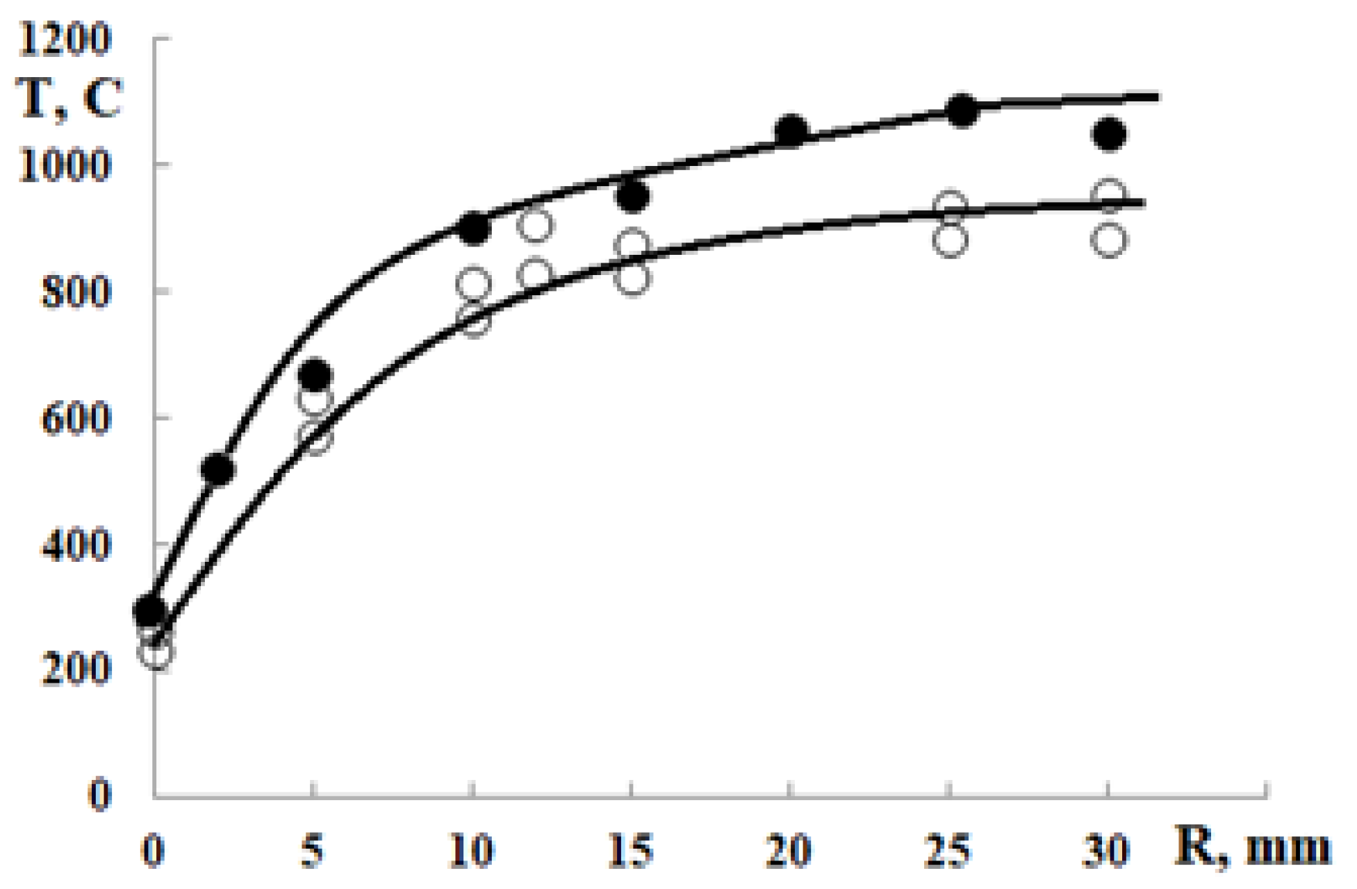
The exhaust gas temperature measured at a distance of 5 mm from the exhaust nozzle significantly depended on the nature of the waste (Figure 6). For the experiments, two different substances (without additional materials), clay and zeolites, were chosen to establish such dependence. Clay and zeolites were selected owing to their well-investigated chemical compositions.
After the melt was released, the arc voltage increased accordingly. According to the results presented in Figure 6, it may be noted that the exhaust gas temperature drops significantly compared with the gas temperature inside the reactor. At an axial distance of up to 30 mm, the behavior of the temperature profiles also depends on the PT operating time because the thermal energy flow rate increases insignificantly, and the temperature of the reactor walls increases. When the axial distance exceeded 25 mm and the reactor wall temperature stabilized, the exhaust gas temperature depended mainly on the arc current. The essential difference between the case of clay and zeolite is that the gas enthalpy of melted clay particles is much larger than that of zeolites. It was also observed that the exhaust gas flow temperature suddenly decreased because of the decrease in its full pressure and density. This phenomenon is absent in high-temperature flows, as the flow expansion possibility towards the axis counterbalances the total pressure decrease. When the surrounding gas leaves the reactor, its exhaust nozzle generates large eddy movement interacting with the surrounding gas. Thus, the processes of increasing turbulence and drawing in the surrounding flow are interrelated. During the experiments, it was noticed that the profiles of the temperatures and enthalpies in the flow direction became nearly symmetrical. This implies that the additional flow is injected into the main two-phase flow from the surrounding layers in inverse proportion to its density. Because of the large amplitudes and durations of the eddies, considerable density fluctuations and transversal mass transfer occur.
From the experimental results of thermal characteristics, it can be seen that it is also possible to establish the dependence of exhaust gas temperature on arc current and length. It was found that the PT thermal stability was reached with increasing arc current or arc length only at a distance of x > 30 mm. In this case, the region appears where the arc power is inversely proportional to the arc current. Temperature measurements (Figure 6) of the gas leaving the reactor showed that the temperature difference between the emission gases during the processing of both zeolites and clay was not high and reached approximately 200 °C (Figure 7). During the experiments, the plasma torch power was 41 kW in both cases, and the air flow was 3.63 g/s. More gas is released when only clay is used than when zeolites are used. This can also be seen by observing the flue gas flowing out of the reactor (Figure 7). The chemical composition of clay includes various metal oxides and salts (K, Mg, Na, Fe, etc.) that react with plasma gas during the treatment process and affect the color of the flame. The mixture for the plasma treatment was prepared and weighed, and its volume was determined. After performing plasma treatment, the melt and unmelted masses were collected and weighed, and the volume of the resulting melt was determined again. It was repeated in every experiment. The amount of clay raw material entering the plasma-chemical reactor was 3.59 kg, and the total amount of the melted fraction collected from the reactor was 3.4 kg. The difference between the material introduced into the reactor and the collected material was 190 g. This amount consists of the gas phase and products that exit the reactor nozzle uncontrollably. According to the obtained results, it was compared and found that the volume of the raw material and the received product differ by a factor of 1:10–1:12.
It is also known that by employing plasma technology, it is possible to process complex wastes, consisting of both organic and inorganic components, and ultimately produce stable, completely harmless end-products. At the same time, a significant reduction in the volume of waste is achieved (up to 95%), and the resulting solid residues contain harmful components in a bound, safe state [22,25,28]. These vitrified products can be stable for hundreds of years.
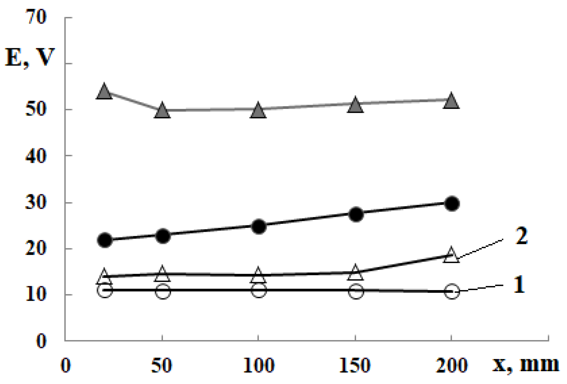
The electric field strength and gas temperature inside the plasma-chemical reactor during the operation were measured using a specially designed thermocouple system, and the measurement results are shown in Figure 8. Here, “x” is the distance from the reactor cover bottom.
The heat loss with the cooling plasma torch water was also analyzed in this study. The heat loss by the cooling PT was relatively small; at I = 50 A, P = 45 kW, and x = 200 mm, the heat loss value with the cooling water was only 1.03 kW, which is approximately 2.28% of the total PT power. Such low heat loss values were due to the presence of PT inside the PChR walls protected by a relatively cold refractory material.
The obtained results show that, in the processing of zeolites containing aluminum and silicon oxides, the electric field strength and gas temperature inside the reactor are lower than those in clay processing. These results are analogous to the reactor flue-gas measurements. The electric field strength of the arc at the start of the reactor is insignificant. However, during operation, when the operating mode is established and the ambient temperature inside the reactor is high, the voltage reaches 50–60 V (
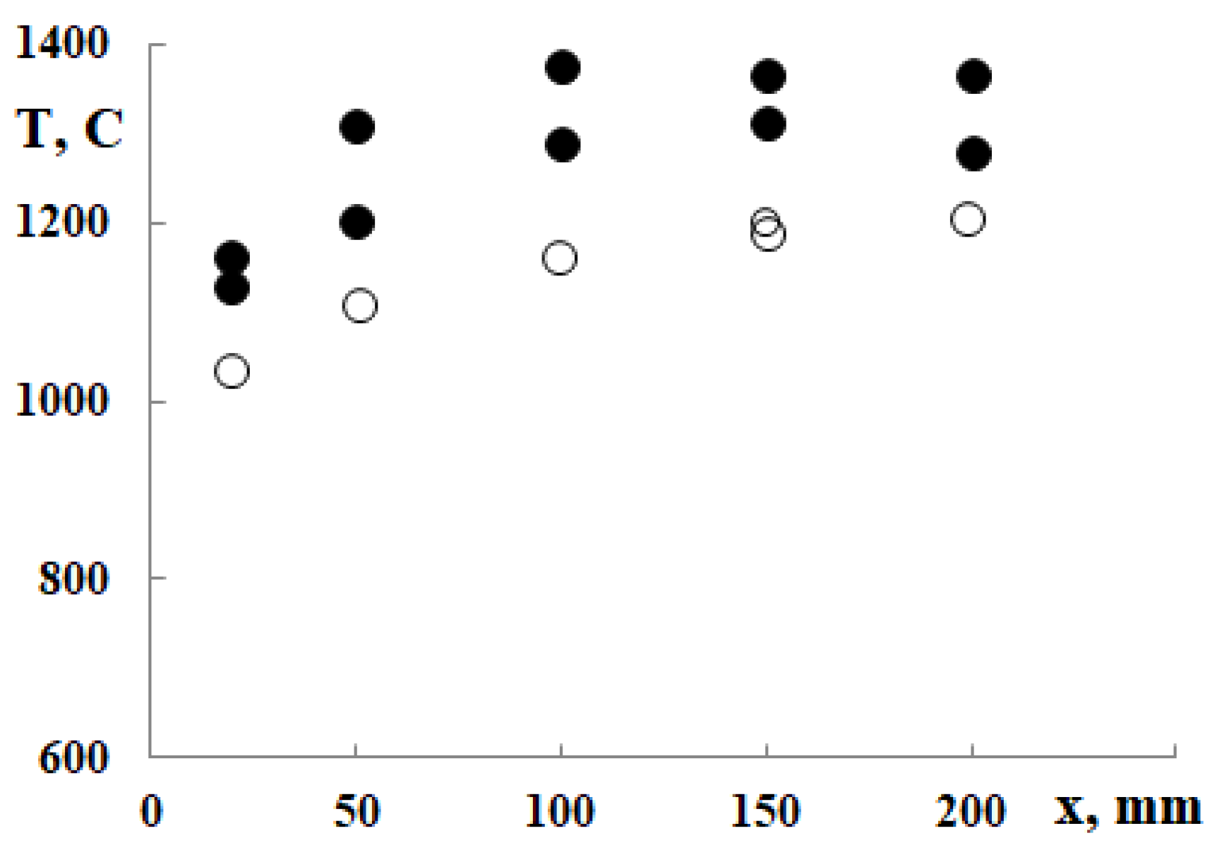
Figure 8). The temperature in the plasma-chemical reactor was measured after 15–20 min of start-up of the reactor. As can be seen from the obtained results (Figure 9), the ambient temperature in the reactor’s entire volume is practically stable.
The erosive wear of the cathode material in the plasma torch is determined by the arc power (the magnitude of the operating current), the composition of the electrode material, the mode of operation, and the properties of the plasma-forming gas. In our case, the arc power is less than 50 kW at an arc current of 180 A, the cathode material is hafnium, the mode of operation is hot cathode cooling by water, and the plasma-forming gas is air or nitrogen. At such conditions, the erosion of the hafnium cathode is about 0.2 g/h. However, the frequent stopping and restarting of the plasma torch significantly reduce the work resource of its cathode. The results of cathode erosion are described in more detail in our paper [29].

3.3. Energy Balance

When hazardous waste is treated in a plasma-chemical reactor, the organic part of waste (including toxic substances) and complex inorganic compounds are mainly decomposed by direct interaction with an electric arc and gas thermal radiation, while the non-combustible amount of waste is partially evaporated (non-combustible part of waste with a low melting point) and is removed from the reactor together with the exhaust gases. The remaining non-combustible waste is melted and accumulates at the bottom of the reactor, where it continues to function as an anode. The melt was collected at the reactor anode and transferred to a container. In order to establish thermal balance, it is necessary to evaluate all thermal processes occurring in a plasma-chemical reactor, neutralize hazardous substances and determine their performance. It would include the following:
  • Q1—plasma torch power;
  • Q2—the energy released in the reactor during exothermic reactions, if any;
  • Q3—energy loss associated with all parts of the plasma-chemical reactor cooling;
  • Q4—energy losses related to endothermal reactions in the reactor, if any are run.
So, the energy balance equation would be the following:
Q 1 + Q 2 = Q 3 + Q 4 + .   ( k W )
Here, Δ is an error that evaluates assumptions, measurements, calculations, etc.
Plasma torch and plasma-chemical reactor tests were performed using zeolite granules and clay as waste. The estimated energy consumption for the molten material amount obtained is listed in Table 2. By using the energy balance equation, the amount of energy used to process the raw material can be calculated as follows:
Q = Q 1 Q P R Q C R Q E X Q 6 .   ( k W )
Here, Q1 is the plasma torch power, which is equal to the transmission of the thermal and kinetic energies of electrons:
Q 1 = I 2.5 k T e e + V a .   ( k W )
QPR is energy loss associated with plasma-chemical reactor cooling. It consists of losses of the plasma torch cooling QP and reactor housing cooling QR.
QCR, in our case, would be heat loss by convection and radiation from the reactor anode and the sole plate.
QEX is the energy of the hot gas exiting the reactor. In our experiment, the exhaust gas flow rate is 1.1 (plasma torch) + 2.63 (shielding gas) = 3.73 g/s.
Q6 is energy loss by exhaust melted domains.
In Equation (3), k is the Boltzmann constant, J/K; Te is the electron temperature, K; e is the electron charge, C; Va is the anode potential, V; and φe is the electron work function, V.
Table 2. The energy consumption, estimated for the total amount of melt.
Q1,
kW
QP,
kW
QR,
kW
QP + QR, kWQ,
kW
Time,
s
Q,
kWh
Amount of Melt,
kg
Specific Heat Flux q,
kWh/(kg∙s)
Clay
37.16.39.215.521.60.5321.525.793.71
Zeolites
40.06.810.817.632.4 0.6726.83.67.44
Calculation methodologies should be developed to assess energy consumption and efficiency factors, etc. After estimating all losses, the numbers would be different. Table 3 lists the energy consumption of the feedstock supplied into the reactor. The plasma torch power was recorded after 15 min. of operating. Later, it begins to decrease as the electric arc length decreases, dependent on the growth of the melt layer.
In the areas where the arc contacted the PT electrodes, the heat flux reached high values through the arc spot. Local heating in this area is very intensive; for conventional PT, only the use of graphite may protect the anode from melting. When an electric arc is used for material processing, very intensive heat fluxes may destroy the material melting. Therefore, the temperature of the process must be regulated.
It is important to note that part of the energy is transmitted by electrons to heavy particles and is included in the convective heat flux. The distribution of arc radiation depends on the degree of the arc blowing from under the electrode towards the walls and the ratio of the electrode diameter and the arc length. According to the experiments, the radiation heat transfer QR for I < 100 A was negligible. According to the experimental data, the heat transfer in the air arc in the range of I = 50–70 A varied by 2–5%. Part of the convective heat flux in the energy balance at the anode side depends on the arc length.
Radially directed electromagnetic forces compress the electric arc during the current passage. In the arc of a variable cross-sectional area (for example, near the cathode), a longitudinal pressure gradient arises because of the action of electromagnetic forces, which increases the generation of a plasma stream from the sites of the constricted area. In the present case, a plasma jet flowed from the cathode toward the anode.

4. Conclusions

A direct current plasma-chemical reactor (PChR) was designed and experimentally tested for solid waste treatment. After experimental investigations to determine process efficiency and quality, it was found that plasma-chemical reactors are practical and have easy-to-use control for regulating temperature, production quantity, and time. In this study, an air plasma torch with a power of 50 kW was developed and used for industrial zeolite and clay waste treatment. The electrical and energy characteristics of the plasma torch and plasma-chemical reactor were investigated. After the plasma treatment, the selected waste was converted into an environmentally friendly melt with much lower volume levels, by approximately 10–12 times, compared to the initial material. The investigation results showed that the behavior of the DC arc burning in plasma-chemical reactors with ambient air is very complex. The voltage-current characteristics in the air flow were measured in the arc current range of I = 50–200 A and at different free arc lengths. The VCCs depend on the arc-burning regime (laminar or turbulent); the arc power increases with the arc current and length. The outflow gas temperature decreases significantly compared with the gas temperature in the volume of the plasma-chemical reactor. At arc lengths greater than 100 mm and arc currents less than 150 A, a significant part of the energy is transferred by convection. At an axial distance of up to 30 mm, the temperature profiles rise in shape and depend on the operating time of the plasma torch. When the axial distance exceeds 30 mm, the reactor’s wall temperature stabilizes, and the exhaust gas temperature depends mainly on the arc current. The proportion of energy transferred by electrons or forced convection to the anode depended on the arc length. The results obtained from the plasma-chemical reactor showed that the ambient temperature in the reactor’s entire volume is stable. The reactor prototype could be used in solid, hardly melting waste treatment processes.

Author Contributions

Methodology, V.V.; software, V.G. and R.U.; validation, D.G., R.U., and Ž.K.; formal analysis, R.U. and V.G.; investigation, V.V., R.K., and R.U.; resources, R.U.; data curation, R.U., V.G., D.G., Ž.K. and R.K.; writing—original draft preparation, V.V., R.K., and R.U.; writing—review and editing, V.V. and V.G.; visualization, V.G. and R.U.; supervision, V.V.; project administration, V.V. All authors have read and agreed to the published version of the manuscript.

Funding

This project has received funding from the Research Council of Lithuania (LMTLT), agreement No. P-LU-22-66.

Institutional Review Board Statement

Not applicable.

Informed Consent Statement

Not applicable.

Data Availability Statement

Not applicable.

Conflicts of Interest

The authors declare no conflict of interest.

References

  1. Young, G.C. Municipal Solid Waste to Energy Conversion Processes: Economic, Technical and Renewable Comparisons; Wiley: Hoboken, NJ, USA, 2010; 396p. [Google Scholar] [CrossRef]
  2. Nishikawa, H.; Ibe, M.; Tanaka, M.; Takemoto, T.; Ushio, M. Effect of DC steam plasma on gasifying carbonized waste. Vacuum 2006, 80, 1311–1315. [Google Scholar] [CrossRef]
  3. Chang, H.O. Hazardous and Radioactive Waste Treatment Technologies Handbook, 1st ed.; Chang, H.O., Ed.; CRC Press Taylor & Francis: Boca Raton, FL, USA, 2001; 792p. [Google Scholar]
  4. Zhovtyansky, V.A.; Petrov, S.V.; Lelyukh, Y.I.; Nevzglyad, I.O.; Goncharuk, Y.A. Efficiency of Renewable Organic Raw Materials Conversion Using Plasma Technology. IEEE Trans. Plasma Sci. 2013, 41, 3233–3239. [Google Scholar] [CrossRef]
  5. Luche, J.; Falcoz, Q.; Bastien, T.; Leninger, J.P.; Arabi, K.; Aubry, O.; Khacef, A.; Cormier, J.M.; Lédé, J. Plasma Treatments and Biomass Gasification. IOP Conf. Ser. Mater. Sci. Eng. 2012, 29, 012011. [Google Scholar] [CrossRef] [Green Version]
  6. Kirkok, S.K.; Kibet, J.K.; Kinyanjui, T.K.; Okanga, F.I. A review of persistent organic pollutants: Dioxins, furans, and their associated nitrogenated analogues. SN Appl. Sci. 2020, 2, 1729. [Google Scholar] [CrossRef]
  7. Zhang, L.; Xu, C.; Champagne, P. Overview of recent advances in thermo-chemical conversion of biomass. Energy Convers. Manag. 2010, 51, 969–982. [Google Scholar] [CrossRef]
  8. Gomez, E.; Amutha Rani, D.; Cheeseman, C.R.; Deegan, D.; Wise, M.; Boccaccini, A.R. Thermal plasma technology for the treatment of wastes: A critical review. J. Hazard. Mater. 2009, 161, 614–626. [Google Scholar] [CrossRef] [PubMed]
  9. Anshakov, A.S.; Urbakh, E.K.; Radko, S.I.; Urbakh, A.E.; Faleev, V.A. Electric-arc steam plasma generator. Thermophys. Aeromechanics 2015, 22, 95–104. [Google Scholar] [CrossRef]
  10. Zhovtyansky, V.; Valinčius, V. Efficiency of Plasma Gasification Technologies for Hazardous Waste Treatment. In Gasification for Low-Quality Feedstock, 1st ed.; Yun, Y., Ed.; InTech: London, UK, 2018; pp. 165–189. [Google Scholar]
  11. Fabry, F.; Rehmet, C.; Rohani, V.J.; Fulcheri, L. Waste Gasification by Thermal Plasma: A Review. Waste Biomass Valorization 2013, 4, 421–439. [Google Scholar] [CrossRef] [Green Version]
  12. Li, J.; Liu, K.; Yan, S.; Li, Y.; Han, D. Application of Thermal Plasma Technology for Solid Waste Treatment in China: An Overview. Waste Manag. 2016, 58, 260–269. [Google Scholar] [CrossRef]
  13. Sanito, R.C.; You, S.J.; Wang, Y.F. Degradation of contaminants in plasma technology: An overview. J. Hazard Mater 2022, 424, 127390. [Google Scholar] [CrossRef]
  14. Zhang, T.; Zhang, J.; Yu, Y.; Zhang, Z.; Wang, G.G. Up-rotating plasma gasifier for waste treatment to produce syngas and intensified by carbon dioxide. Energy 2023, 270, 126910. [Google Scholar] [CrossRef]
  15. Kėželis, R.; Mėčius, V.; Valinčiūtė, V.; Valinčius, V. Waste and biomass treatment employing plasma technology. High Temp. Mater. Process. 2004, 8, 273–283. [Google Scholar] [CrossRef]
  16. Valinčius, V.; Krušinskaitė, V.; Valatkevičius, P.; Valinčiūtė, V.; Marcinauskas, L. Electric and thermal characteristics of the linear, sectional dc plasma generator. Plasma Sources Sci. Technol. 2004, 13, 199–206. [Google Scholar] [CrossRef]
  17. Valinčius, V.; Kezelis, R.; Gimžauskaitė, D.; Grigaitienė, V.; Valatkevičius, P. The investigation of an electric arc in a plasma chemical reactor for hazardous waste treatment. J. Chem. Technol. Biotechnol. 2019, 95, 450–456. [Google Scholar] [CrossRef]
  18. Sikarwar, V.S.; Hrabovský, M.; van Oost, G.; Poho, M.; Jeremiáš, M. Progress in waste utilization via thermal plasma. Prog. Energy Combust. Sci. 2020, 81, 100873. [Google Scholar] [CrossRef]
  19. Rada, E.C. Thermochemical Waste Treatment: Combustion, Gasification, and Other Methodologies; Apple Academic Press, Inc.: Oakville, ON, Canada, 2021. [Google Scholar] [CrossRef]
  20. Diaz, G.; Sharma, N.; Leal-Quiros, E.; Munoz-Hernandez, A. Enhanced Hydrogen Production Using Steam Plasma Processing of Biomass: Experimental Apparatus and Procedure. Int. J. Hydrogen Energy 2015, 40, 2091–2098. [Google Scholar] [CrossRef]
  21. Rutberg, P.G.; Kuznetsov, V.A.; Serba, E.O.; Popov, S.D.; Surov, A.V.; Nakonechny, G.V.; Nikonov, A.V. Novel Three-Phase Steam–Air Plasma Torch for Gasification of High-Caloric Waste. Appl. Energy 2013, 108, 505–514. [Google Scholar] [CrossRef]
  22. Hrabovsky, M.; Jeremiáš, M.; Van Oost, G. Plasma Gasification and Pyrolysis; CRC Press, Taylor & Francis Group, LLC: Boca Raton, FL, USA, 2023; 104p. [Google Scholar] [CrossRef]
  23. Galaly, A.R.; Van Oost, G. Environmental and Economic Vision of Plasma Treatment of Waste in Makkah. Plasma Sci. Technol. 2017, 19, 105503. [Google Scholar] [CrossRef] [Green Version]
  24. Ruj, B.; Ghosh, S. Technological Aspects for Thermal Plasma Treatment of Municipal Solid Waste—A Review. Fuel Process. Technol. 2014, 126, 298–308. [Google Scholar] [CrossRef]
  25. Tazmeev, B.; Tazmeeva, R.; Pogosyan, V. Parameters of a gas discharge with a liquid electrode in the process of gasification of hydrocarbon-containing waste. E3S Web Conf. 2021, 285, 08007. [Google Scholar] [CrossRef]
  26. Snapkauskienė, V.; Valinčius, V.; Valatkevičius, P. Heat transfer in the Arc discharge channel. Heat Transf. Res. 2009, 40, 399–413. [Google Scholar] [CrossRef]
  27. Vargaftik, N.B. Tables on the Thermophysical Properties of Liquids and Gases, 2nd ed.; Halsted Press; Division of John Wiley & Sons, Inc.: New York, NY, USA, 1975; 758p. [Google Scholar]
  28. Lee, S.; Speight, J.G. Handbook of Alternative Fuel Technologies, 2nd ed.; CRC Press; Taylor & Francis Group: Boca Raton, FL, USA, 2015; 650p. [Google Scholar]
  29. Kezelis, R.; Valatkevicius, P.; Mecius, V. Cathode’s assembly design and air supply rate’s influence to industrial plasma generator’s cathode life time. Conf. Mater. SAP ETEP 1997, 97, 74–76. [Google Scholar]
Figure 1. The diagram of plasma-chemical waste decomposition.
Applsci 13 04221 g001
Figure 2. The scheme of the plasma-chemical reactor. 1—raw material input, 2—plasma torch, 3—graphite plate (anode), 4—cooling flow inlet, 5—Chromel–Alumel thermocouple, 6—cooled probe for gas sampling.
Applsci 13 04221 g002
Figure 3. Schematic of the experimental plasma torch. 1—outside casing, 2—cathode holder, 3—insulating ring, 4—hafnium cathode.
Applsci 13 04221 g003
Figure 4. Dependence of arc voltage on its length. Arc current (A): 1—160, 2 and 3—150, 4—200, 5 and 6—180. Line A—plasma torch operates with waste, B—without waste. Air inlet flow rate: plasma torch—1 g/s, protecting gas—2.63 g/s.
Applsci 13 04221 g004
Figure 5. Dependence of the electric arc voltage on the plasma-chemical reactor operating time: 1 (black dots)—recycled zeolites, 2 (white dots) —recycled clay. A is the arc voltage after the melt is released. The air flow through the plasma torch was 1 g/s, and the protective gas was 2.63 g/s.
Applsci 13 04221 g005
Figure 6. Radial distribution of gas temperature leaving the plasma-chemical reactor. White dots—when working with zeolites; black dots—with clay. The air flow through the plasma torch was 1 g/s, and the protective gas was 2.63 g/s.
Applsci 13 04221 g006
Figure 7. View of the reactor exhaust gas glow.
Applsci 13 04221 g007
Figure 8. The electric field strength in the operating reactor when working with: 1—zeolites and 2—clay. White dots—after starting the reactor, dark—after 30 min of the start. The airflow through the plasma torch was 1 g/s, and the additional gas flow rate was 2.63 g/s. The PT power was 41 kW.
Applsci 13 04221 g008
Figure 9. The axial temperature distributions in the operating plasma-chemical reactor worked with: white dots—zeolites, and black—clay. The air flow through the plasma torch was 1 g/s, and the protective gas flow rate was 2.63 g/s. The PT power was 41 kW.
Applsci 13 04221 g009
Table 1. Operating parameters of the plasma-chemical reactor.
ParameterOperating Regime
12
Arc current I, A160160
Arc voltage U, V280–235275–220
Arc power P, kW44.8–37.644.0–35.2
Plasma-forming gas flow rate G1, g/s0.90.9
Additional gas flow rate G2, g/s2.632.63
Initial distance anode–cathode x, mm100–50100–50
Operating time, min1–401–40
Table 3. Energy consumption based on the amount of feedstock.
Q1,
kW
QP,
kW
QR,
kW
QP + QR,
kW
Q,
kW
Time,
s
Q,
kWh
Amount of Melt,
kg
Specific Heat Flux q,
kWh/(kg∙s)
Clay
37.16.39.215.521.60.5321.526.13.53
Zeolites
40.06.810.817.632.4 0.6726.85.25.15
Disclaimer/Publisher’s Note: The statements, opinions and data contained in all publications are solely those of the individual author(s) and contributor(s) and not of MDPI and/or the editor(s). MDPI and/or the editor(s) disclaim responsibility for any injury to people or property resulting from any ideas, methods, instructions or products referred to in the content.

