1. Introduction
Matrix converters gained considerable interest in the sphere of research and universities in recent years [
1,
2,
3,
4]. In high power density applications [
4,
5] or applications with large temperature variations, the lack of the DC-Link capacitor or inductor is beneficial over the normal VSI design.
Direct matrix converters (DMCs) were long viewed as an appealing AC/AC choice due to their sinusoidal input/output currents, bidirectional power flow, and customizable input power factor. As a result, it is a competitive topology that may be used in a wide range of electrical equipment, including industrial pumps, cooling, refrigeration, elevators, belt transportation systems, and avionic applications [
6,
7].
Direct matrix converters (DMCs) and the bidirectional switches (BDSs) have changed throughout time. Each BDS, in an instance, can be achieved by a single monolithic device [
7], which is not yet accessible, or by some combination devices [
8,
9] to offer bidirectional current conduction when activated and bidirectional voltage blocking when deactivated. Because a bidirectional switch constructed in a single monolithic semiconductor that could conduct and block current and voltages in both directions is not available, bidirectional switches must be designed utilizing discrete components such as IGBTs, MOSFETs, or RB-IGBTs. However, recent news from new GaN technology may overcome this problem, and researchers recently focused their efforts on this area as well [
10,
11,
12].
When a high-power density is required, the power loss analysis is an important aspect of the converter design approach. If power losses are not examined under various operating situations, the cooling solution design may be insufficient. The analytical technique is a common procedure for calculating losses. This method can be time-demanding due to the extensive analysis of the matrix converter increased number of semiconductors [
13,
14,
15,
16,
17,
18,
19]. Another method is to use numerical analysis with semiconductor models. If transistor models are available, this technique is more efficient [
20].
If any operating circumstances, such as converter start-up, fault conditions, and others, must be evaluated, numerical analysis is particularly helpful. The goal of this study is to analyze the potential benefits of SiC transistors in matrix converter applications, as stated in the switch analysis part of this paper. The transistor and diode models were used to mimic the power component of the matrix converter in a 3 × 5 arrangement suited for multiphase drives [
21]. In addition, all of the power components of the matrix converter’s building parts, such as the protection network, current direction detecting circuit, and input filter, were simulated to determine the entire efficiency of the converter.
2. Bidirectional Switch Analysis
The IGBT transistor is used to provide a bidirectional switch in the majority of matrix converters [
6,
22,
23,
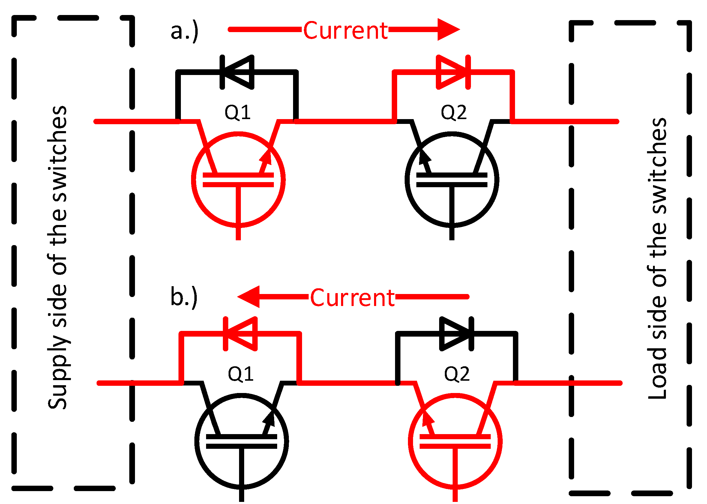
24]. Even some manufacturers, such as SEMIKRON, produce modules with IGBT switches suitable for use in matrix converters, such as the SKM150GN12T4G or SKM400GM17E4. The switches mentioned are only available in high-power designs, which are not suitable for low or mid-power applications due to their high cost, possibly large power losses, and low power density. However, IGBT switches are well established, dependable, and can even survive a short circuit current for a short period, which can be useful in matrix converter applications. The significant drawback, on the other hand, is the current flow distribution in the switch during positive or negative flow, as seen in
Figure 1.
As shown in
Figure 1a, the current travels in a positive direction (from the power source to the load) via Q1 and then, through the internal diode of Q2. Conversely, the negative current (from the load to the power supply) flows via Q2 and then through Q1 internal diode. As previously established, current will always flow via one transistor and one diode even if both transistors are fully open. This is due to the technology utilized in IGBT transistors. The resulting conducting power losses in this sort of bidirectional switch may be represented as:
where
IAV denotes the average current flowing through the bidirectional switch and
VSAT and
VF denote the IGBT saturation voltage and internal diode forward voltage, respectively. The following characteristics can be noticed while using a random average 1200 V IGBT, such as the STGW15H120DF2. The voltage drop at the separate sections of the IGBT is shown in
Table 1.
As can be observed, the diode voltage drop is quite substantial, which can result in high power losses, particularly at low power outputs, lowering the matrix converter’s efficiency dramatically. SiC technology, on the other hand, is now quite popular in power electronics due to its benefits. They provide a very high blocking voltage while also having a low RDSon of the transistor. Because the driving circuits are simple and SiC semiconductors can function at high frequencies, the overall volume of the converter’s passive components may be kept to a minimum.
Another feature of MOSFET-based SiC semiconductors is the channel ability to conduct current in both directions. This mode of operation is known as inverse conduction, and most manufacturers include a description of it in their product datasheet. The reverse conducting capability in matrix converter applications can have a significant impact on power losses and converter efficiency. If a negative voltage is given to the Drain-Source channel and the transistor is positively biased (VGS is positive), the channel will conduct current from Source to Drain if the following equation is true:
The current will pass through both the SiC channel and the intrinsic diode in the circumstance when the right side of Equation (2) is somewhat higher than the left side. If the voltage drop on the channel is less than the internal diode threshold voltage VF, current flows exclusively via the MOSFET channel. This scenario is depicted in
Figure 2.
If both transistors are positively biased and the voltage drop in the channel is less than the threshold voltage of the internal diode,
Figure 2 represents both current directions (positive and negative). We can express the power losses in this type of switch using this assumption as follows:
Because the RDSon values of SiC semiconductors can range from 20 to 110 mΩ, the power losses created in the matrix converter based on the MOSFET can be greatly decreased according to Equation (3) when compared to Equation (1) for the IGBT switch.
3. Analytical Power Losses Calculation in Matrix Converter
Due to the system symmetries, the global conduction power losses can be easily derived. In the 3 × 5 matrix converter, every output phase has three switches connected to the input phases U, V, and W. Thus, output current determines power losses in all three bidirectional switches. For the IGBT-based matrix converter, the output phase current must be split to the positive and negative components, because due to the analysis in
Figure 1, positive current flows through transistor Q1 and the internal diode of Q2, and negative current flows through transistor Q2 and the internal diode of Q1. Then, we can calculate average and rms current as follows [
15]:
where
IPK represents the peak value of the output current of the matrix converter. Losses in one bidirectional switch can be then calculated using:
Then, global power losses of one semiconductor can be calculated as follows [
15]:
With the use of formula, we can calculate the conducting power losses in the 3 × 5 IGBT-based matrix converter.
In the SiC (MOSFET)-based bidirectional switch, the situation is slightly different. Because the MOSFET transistor has channel with resistive character when conducting, bidirectional switch has only resistive power losses. Then, Equation (6) must be adjusted, and power losses in one MOSFET transistors can be calculated:
where
IPK is the peak value of the output current and r represents
RDS(on) of one MOSFET transistor in the bidirectional switch. For the global power losses in the 3 × 5 matrix converter,
r can be substituted as follows:
The components parameters were used to calculate power losses using this analytical approach and results can be seen in comparison chapter of this paper.
4. Model of the MxC Converter in MATLAB Simulink
The matrix converter simulation was carried out using the Simulink Simscape environment. For the power loss investigation, three models were simulated and investigated.
The first model used SiC transistors in the bidirectional switch. Additionally, for the proper current commutation, the direction of the current of every output phase must be known. For this purpose, additional antiparallel diodes were connected at the output of every phase of the matrix converter to reliably detect the current direction.
The second model used the IGBT transistor in bidirectional switches to compare losses to the SiC one. The current direction diodes were left in the circuit.
Finally, the third model bidirectional switches were based on IGBT transistors too, but direction diodes were removed. Instead of bidirectional diodes, the voltage drop at the transistor of the bidirectional switch was measured and evaluated. If the value was higher than 2.8 V, according to
Table 1, the current was reportedly flowing through the internal diode of the IGBT; thus, current direction was negative. If the voltage drop was below 2.8 V, the current was flowing through IGBT itself and the current was positive. This approach requires additional circuits and comparators, but the losses generated at the direction detection diodes can be eliminated, which can lead to higher efficiency.
For the simulation, indirect control using vector modulation was used. The matrix converter is virtually split into two parts, a virtual rectifier and a virtual inverter. Both parts can be controlled separately with their gains, respectively. The resultant switching pulses are then transferred from the indirect to the direct topology using the following matrix [
25]:
where individual switches correspond to the switches in the indirect and direct matrix topology, as shown in
Figure 3.
Additionally, the matrix converter requires an input filter for the proper function and for the current drawn from the grid to be sinusoidal. The filter will have additional losses; thus, the filter was modeled to the simulation too. The chosen filter was the LC damped filter due to its relatively low component count and good performance. The LC filter is unstable around its resonant frequency, which can cause problems during the matrix converter operation, especially during low output powers and step load changes. Multiple damping solutions are known for the LC filter, and for this application, the resistor parallel to the inductor as a damping component was chosen, due to its good damping, low cost, and simplicity. The parameters of the used filter are summarized in
Table 2.
5. Simulation Results
5.1. Simulation of Power Losses in IGBT-Based Bi-Switch with External Current Direction Detection Diode
During the simulations, the constant gain of the virtual rectifier q
RECT was maintained at its maximum value of 1. The gain of the virtual inverter was changed from 0.1 to its maximum value of 1.6. The load for the matrix converter was represented with a five-phase RL circuit with values of R = 7.8 Ω and L = 30 mH. The input power supply was simulated by three phase voltage sources with voltages set to 90 V RMS and frequency of 50 Hz. Three simulations were conducted with devices and parameters shown in
Table 3.
The simulation parameters of the devices used in the simulation from
Table 3 were acquired from the datasheets of the mentioned parts. Direction diode and the MOSFET were also used in the experimental verification of the power losses. First, the simulation using IGBTs as components of the bidirectional switch was simulated. The results can be seen in
Figure 4.
As can be seen, most of the power losses were represented by the bidirectional switches. This is because current is always flowing through the IGBT/Diode pair, which can be seen in
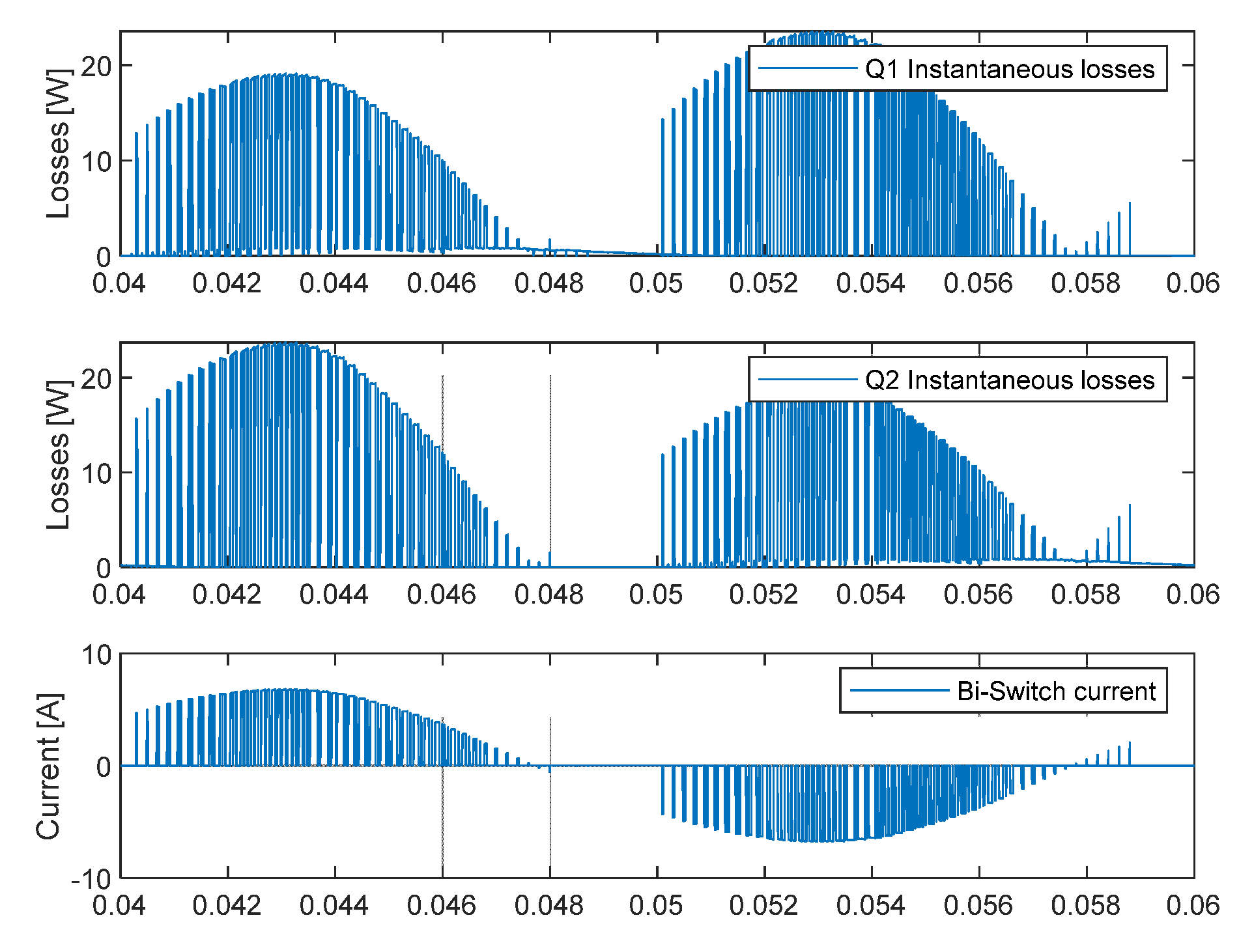
Figure 5.
The upper subplot in
Figure 5 shows power losses at the Q1, according to
Figure 1. The current flowed from the Source to the Load according to the current direction. The power losses in Q1 were generated at the IGBT itself, and in Q2, the power losses were generated at the internal diode. The internal diode losses were higher due to the higher barrier voltage and higher internal resistance of the component. Similarly, when the current flowed from the Load to the Source, the losses were turned around, the losses in Q1 were generated in the diode, and losses in Q2 were generated by the IGBT itself. Other losses generated in the MxC were in the current direction diodes as well as in the input filter. At the value of the q
INV = 1.6, the bidirectional switches losses were 130 W, direction diodes losses were 16.8 W and input filter losses were 11.25 W. The total output power at the q
INV = 1.6 was 860.78 W.
5.2. Simulation of Power Losses in IGBT-Based Bi-Switch without External Current Direction Detection Diode
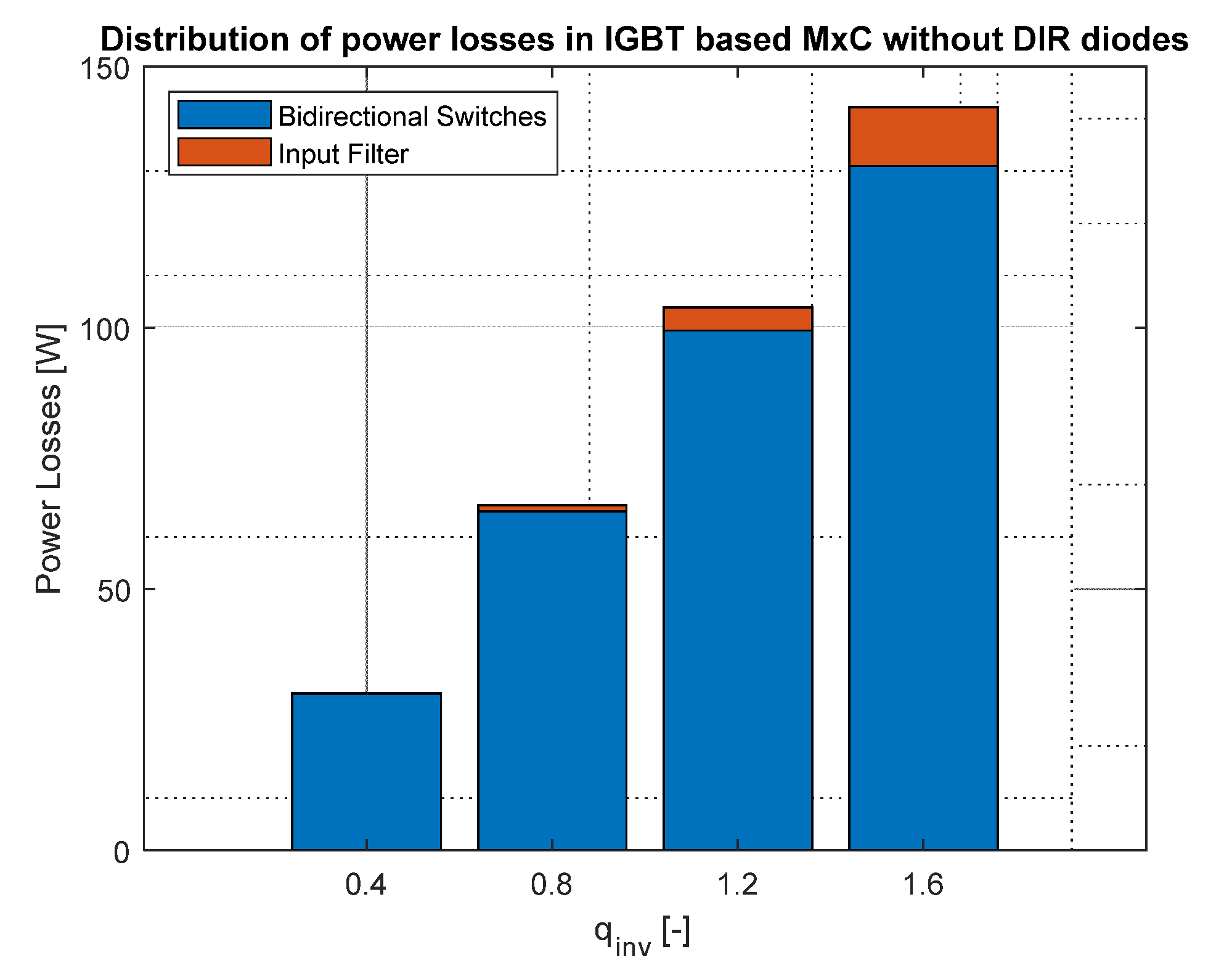
However, the direction of the current in the IGBT-based bidirectional switch can be detected using one of the IGBTs, as described earlier, the model was redesigned, and the power losses without direction-detection diodes are shown in
Figure 6.
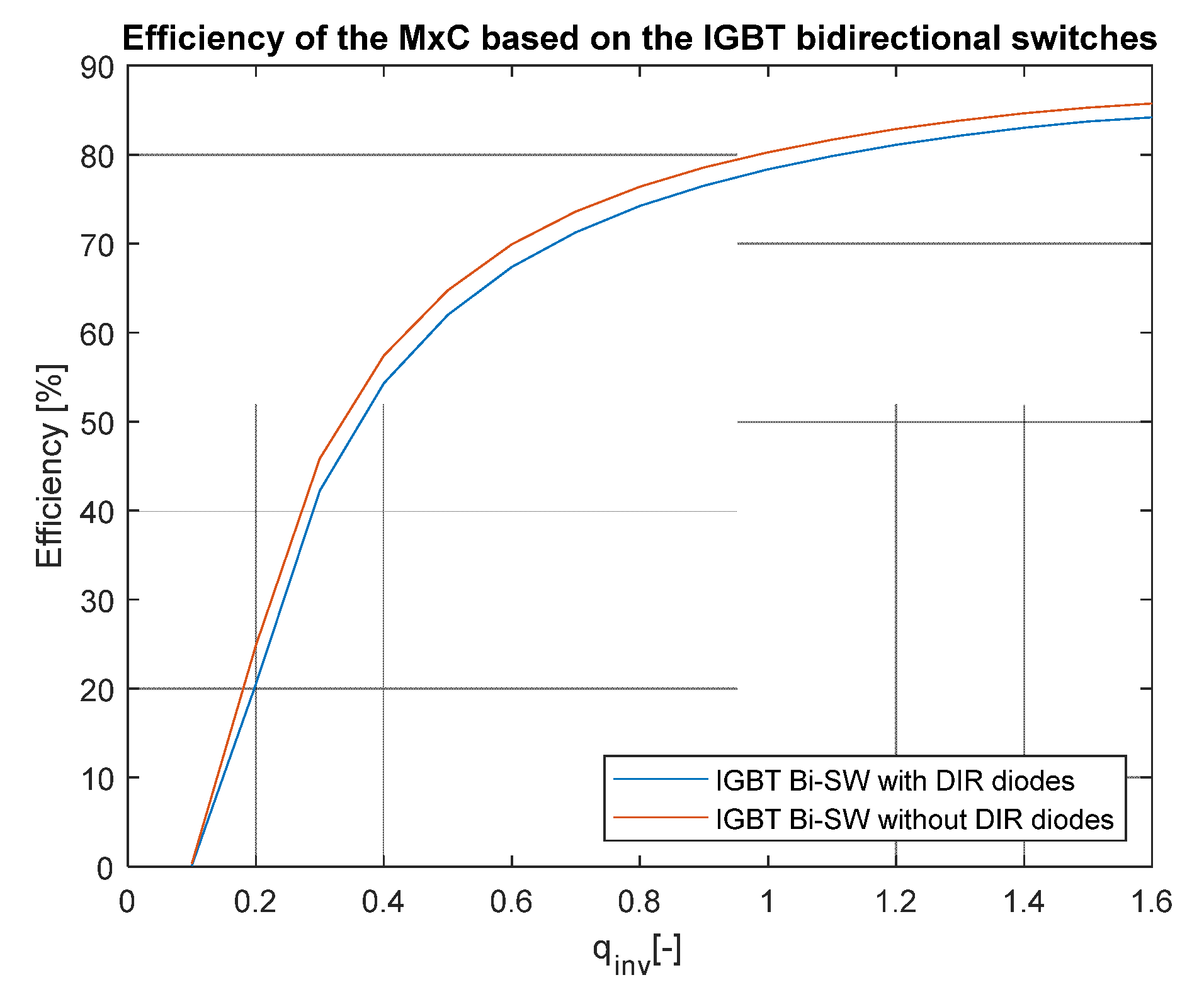
As can be seen, the power losses at higher output powers dropped significantly due to the absence of the detection diodes. The efficiency of both models is shown in
Figure 7:
The peak efficiency of the IGBT-based matrix converter with direction diodes was 84.1% at the output power of 860 W and the model without direction detection diodes reached an efficiency of 85.7% at the 874 W of output power.
5.3. Simulation of Power Losses in SiC-Based Bidirectional Switch
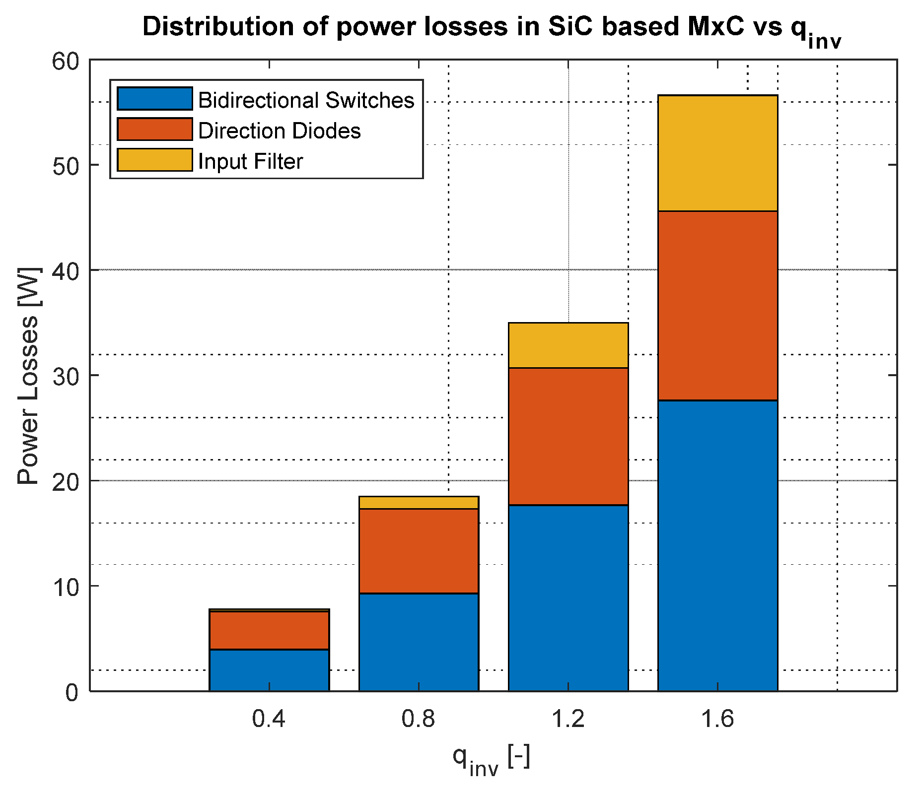
In the next simulation, the matrix converter with SiC bidirectional switches was investigated. The simulation parameters and conditions were the same as for previous models. The distribution of the power losses in the SiC MxC is shown in
Figure 8.
The columns in
Figure 8 show a significant reduction in the power losses of the bidirectional switches because MOSFET can conduct current in the reverse direction, thus effectively eliminating internal body diode losses, which were significantly higher than losses in the conducting channel. The total power losses at maximum output power were 56.6 W, from which switch losses formed 27.6 W, direction diodes were 18 W, and filter losses were 11 W. The total output power of the simulation was 945 W. The output power was higher due to the lower power losses in the power part of the matrix converter. The Simscape library was used to properly implement power losses models of the used semiconductors. Subsequently, m-file script was used to extract all data from the simulation and calculate average values of power losses used in
Figure 4,
Figure 6 and
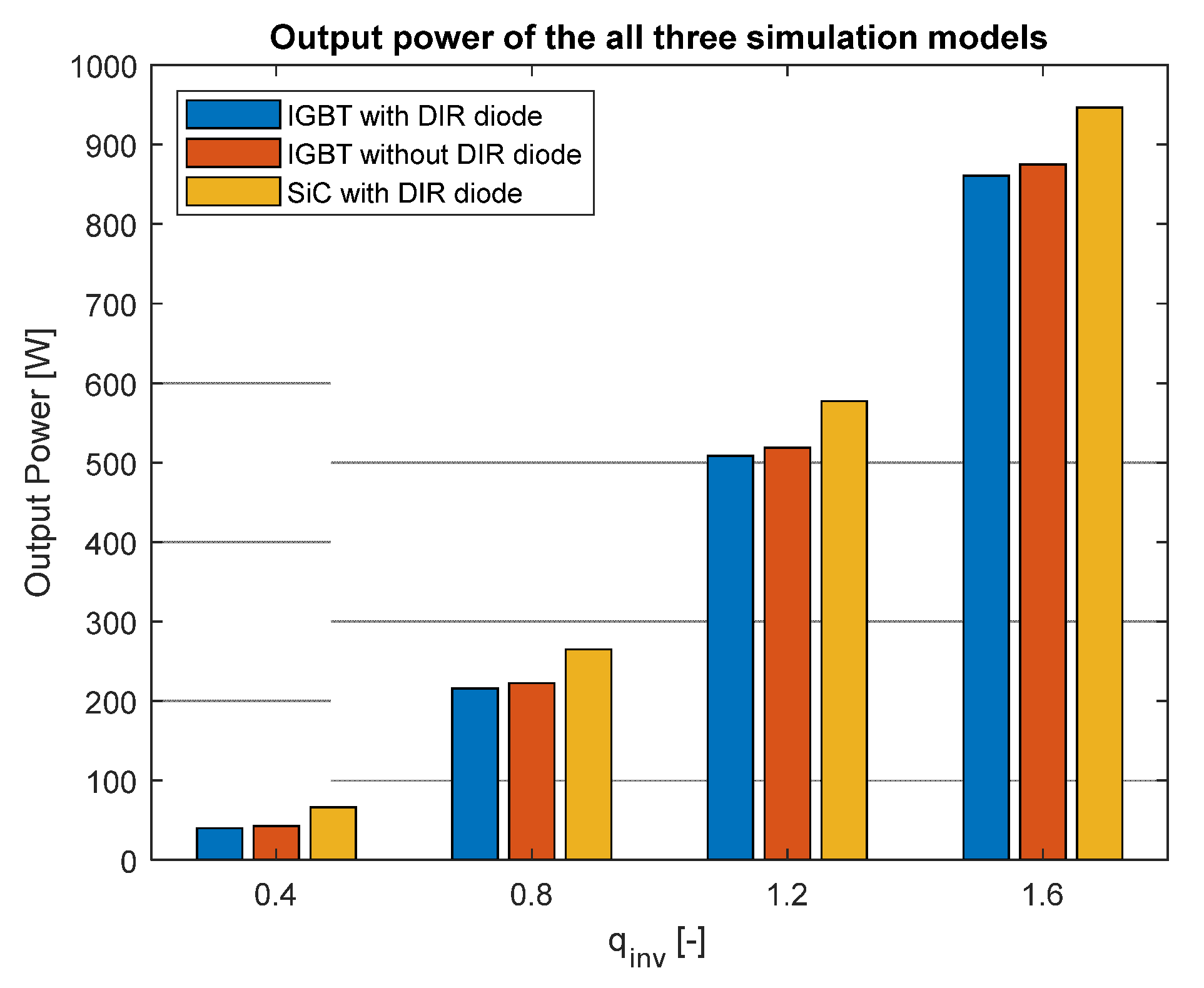
Figure 8. The total output power with every type of switch is shown in
Figure 9.
As we can see, the total output power was very similar, but the output power was higher with the SiC simulation model, due to the lower power losses. This is because the power losses were lowest in this configuration, and were transferred to the output. The efficiency of the simulation model is shown in
Figure 10.
As can be seen in
Figure 10, the highest efficiency of 94.35% was again reached at the maximum value of the q
INV.
6. Comparison with the MxC Prototype
Based on assumptions in the introduction of the paper and the simulation results, the practical prototype of the matrix converter was built. The sample was based on the SiC semiconductors to create a power part of the MxC. Due to the possible comparison with the simulation model, the same SiC and Direction diode as in the simulation was used, as can be seen in
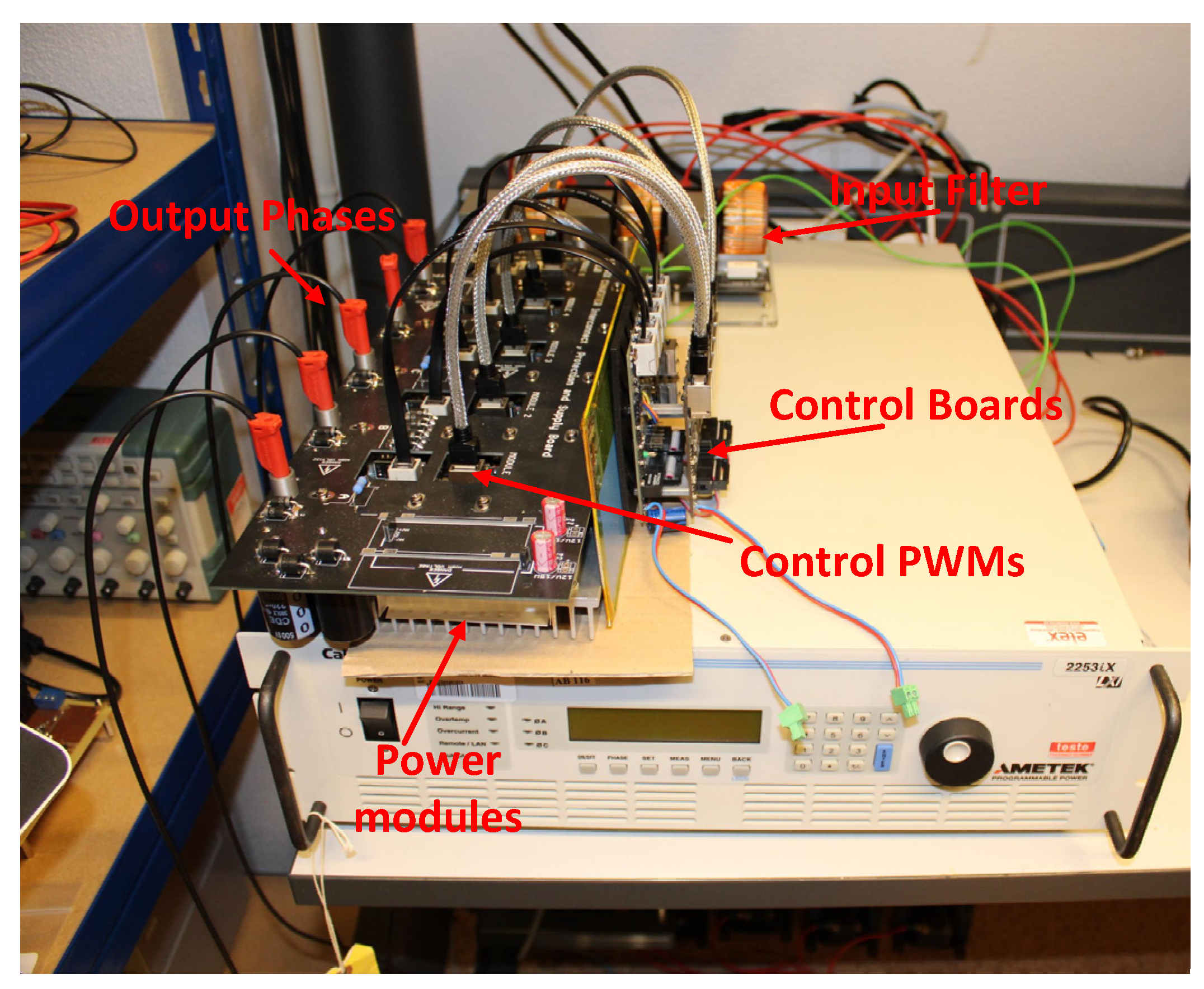
Table 3. Every module contained power transistors together with direction diodes designed at the IMS (insulated metal substrate) board for easy mounting and good cooling. The other part of the module contained drivers for the transistors, as well as the isolated power supplies for the drivers. Every module contained six SiC transistors forming the three inputs and one output configuration. Because of this arrangement, a total of five modules were needed to create a power part of the 3 × 5 matrix converter investigated in this article. The final prototype of the converter is shown in
Figure 11.
Further important parts of the converter were the input filter, control boards, and measurement boards. Control boards are divided into two separate parts: the first is DSP board, which calculates duty cycles, measures currents and voltages, and communicates with the superior system. The second part is FPGA board, which works with vectors and generates switching pulses with commutation delays [
26]. The second board was implemented due to the high computation requirements of the vector implementation and commutation times calculations.
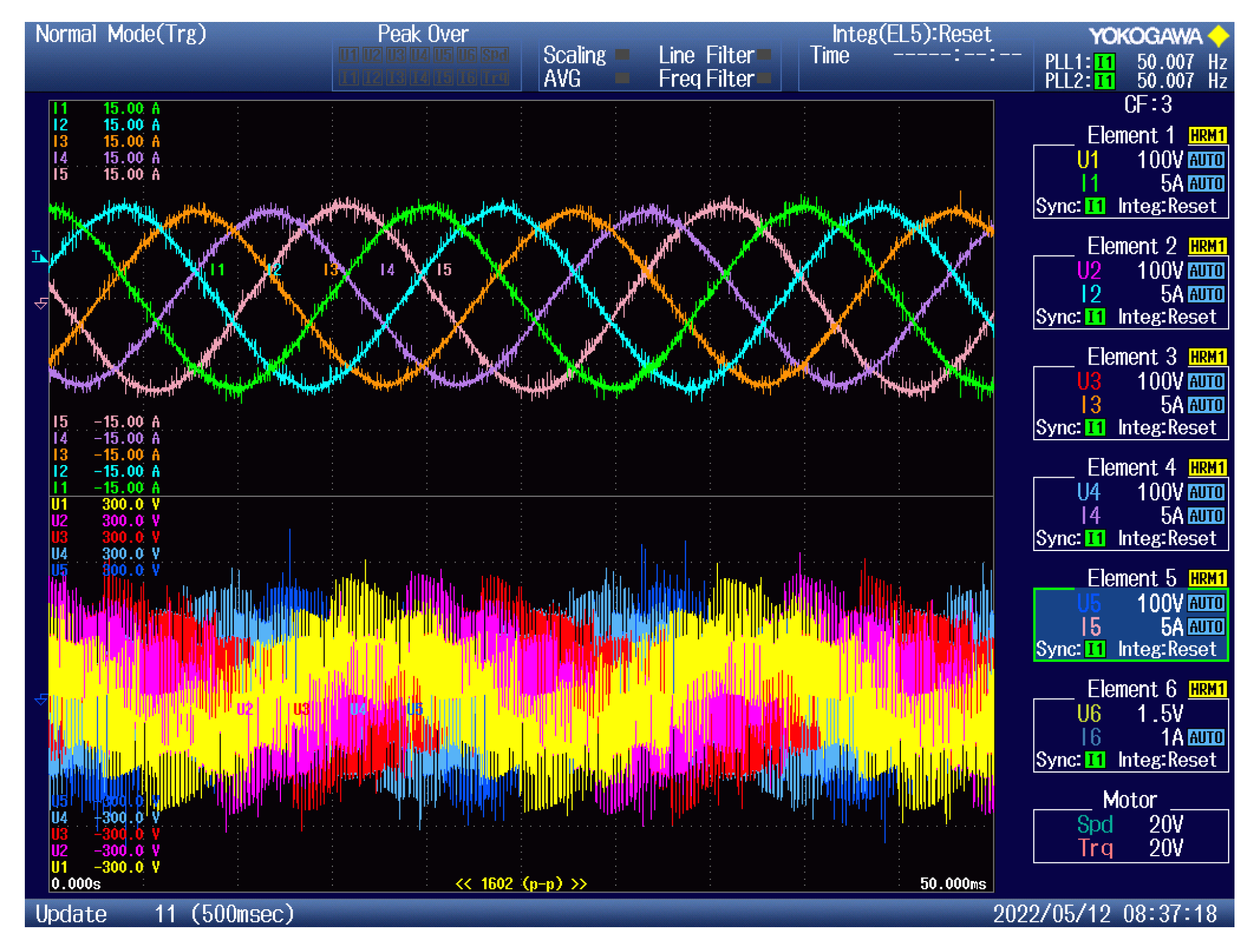
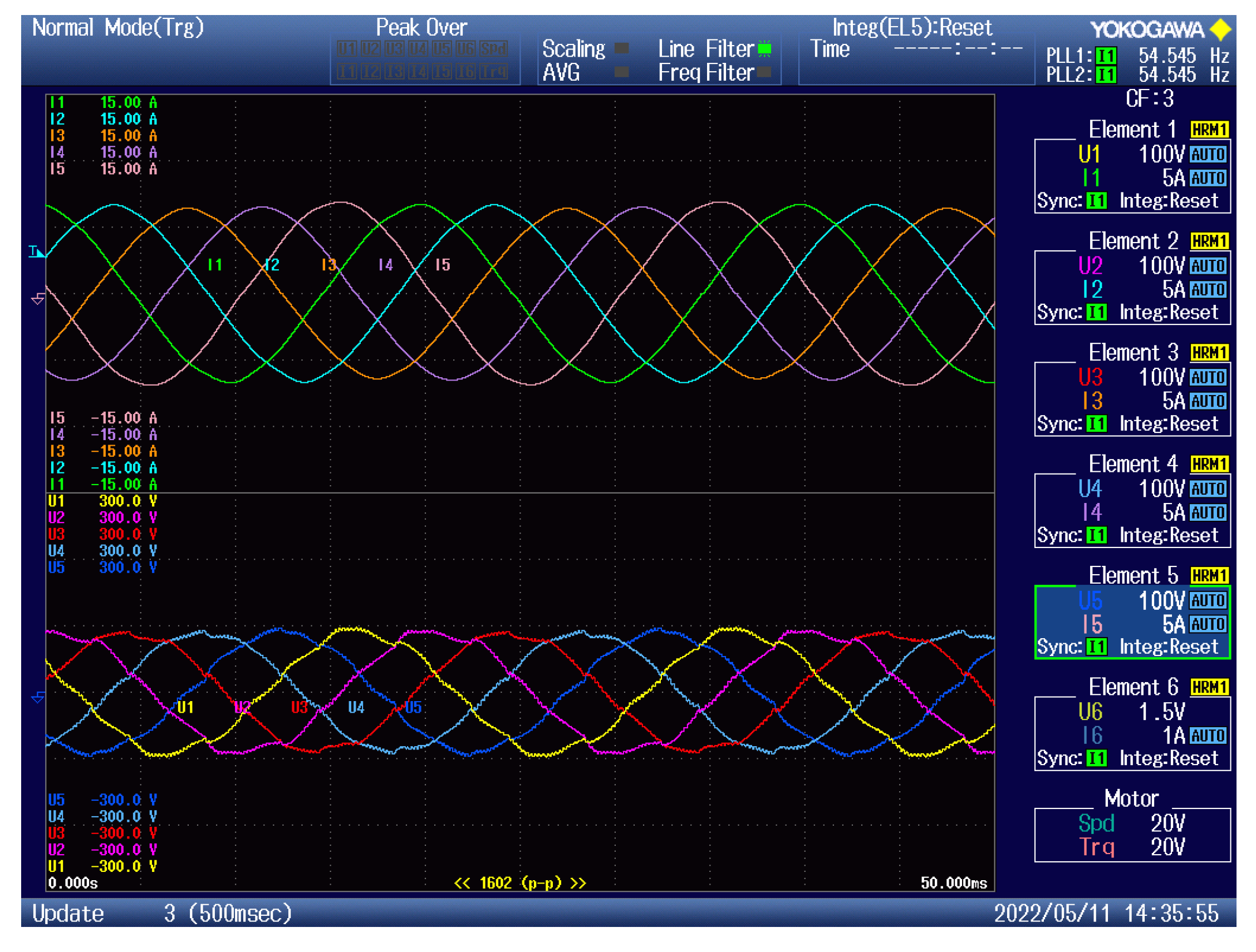
The California instruments three-phase power supply was used to supply power to the prototype of the matrix converter. For the output power measurement and evaluation, the YOKOGAWA precision power analyzer was used, which can measure six channels in total. The measured output currents at the q
INV = 1.6 are shown in
Figure 12.
The input power was measured using the input California power supply, and the output was measured using the mentioned YOKOGAVA analyzer. To phase voltages, the software filter in the YOKOGAWA analyzer was used to better observe the switched voltages and currents. The cut-out frequency of the filter was set to 1 kHz. The results can be seen in
Figure 13.
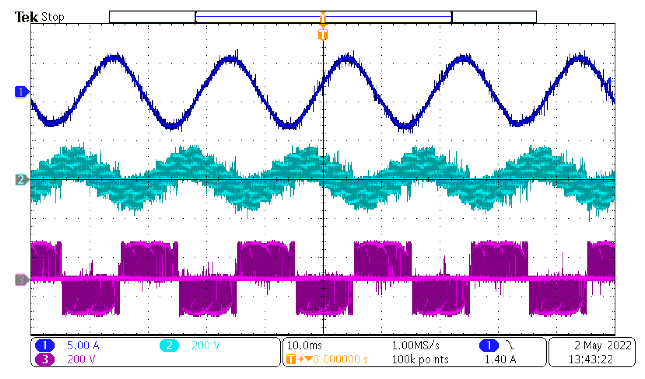
For a better view of the individual quantities at the output of the matrix converter, the measurement at the oscilloscope is presented in
Figure 14.
The waveform in
Figure 14 shows the output waveforms at the five-phase load. The voltages and current matched the theoretical assumptions presented in
Section 3 and simulations results in
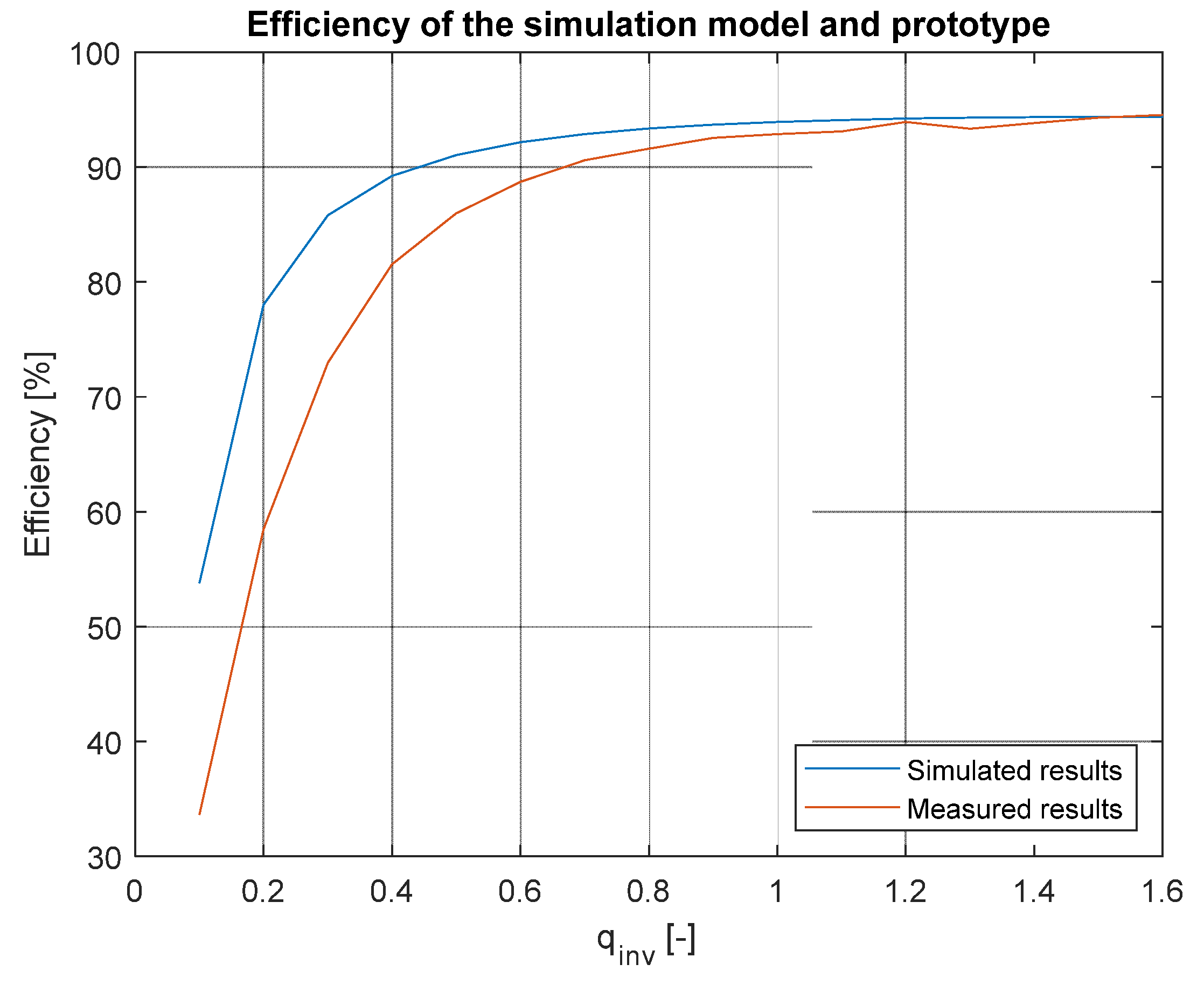
Section 5 of this paper. With the use of the YOKOGAWA analyzer, the efficiency of the converter was measured and compared to the simulation model. The results of the comparison are shown in
Figure 15.
As can be seen in
Figure 15, the simulation and prototype of the matrix converter had a very good match at the higher output powers. At the maximum output power, the difference was only 0.2%. The prototype of the matrix converter reached lower efficiency at the lower output powers because the output current was very noisy, which resulted in the lower efficiency. The simulated efficiency was 94.3% and the measured efficiency was 94.5%.
Finally, the input current and voltage waveforms were compared between the simulation and prototype. The result is shown in
Figure 16.
The match between simulation and the prototype was very good, as can be seen in
Figure 16. The current waveform matched the simulation with its shape and amplitude. This confirmed that the prototype of the MxC worked identically to the simulation model (
Table 4).
7. Conclusions
This paper focused on the investigation of power losses in matrix converters. The introduction section presented IGBT- and MOSFET-based bidirectional switches and analyzed power losses generated in every type of switch. Anylytical simulation was conducted in
Section 3 of this paper, where mathematical calculations of power losses were presented. Parameters of the used components were used in these calculations, where results are shown in
Table 3 and compared to the simulation results from MATLAB Simulink environment, described in
Section 4. These simulation models were created with IGBT and SiC switch to simulate and investigate power losses in a 3 × 5 matrix converter. Three modes were presented, one with a SiC switch and two with a IGBT switch, where the difference was only the methodology of the current direction sensing.
As can be seen in
Figure 7, the efficiency of the IGBT-based MxC was around 85%, whereas the model without direction detection diodes had slightly higher efficiency.
Figure 4 and
Figure 6 show that the majority of the power losses were generated in the IGBT/Diode pair, which significantly decreased available output power and generated the power losses which lowered the efficiency of the solution. The SiC-based MxC showed very high improvement due to the possibility of the inverse conduction of the MOSFETs, and the total efficiency reached with this type of switch was 94.3% which was almost a 10% improvement compared to the IGBT-based MxC.
Based on the simulation, the prototype of the matrix converter was built using the SiC MOSFET due to the lower power losses resulting from the simulations.
The efficiency of the prototype was lower at the lower output powers due to the noisy output power, but at the output powers from 350 W and higher, the results from the simulation and measurement showed a very good match. At the maximum output power, the error between the simulation and prototype was only 0.2%, as shown in
Figure 15.
As shown in the paper, the SiC transistors were a very good option for application in the matrix converter due to the low power losses. Even though, nowadays, the price of the SiC transistors is higher than IGBTs, if the application requires the advantages of the matrix converter as adjustable input power factor and unity power factor, the SiC transistors are a great choice in MxC application. If higher efficiency is required, the transistors in the same package but with lower RDS-ON can be used to lower power losses even more.
In the future work, the practical verification of the five-phase matrix converter on asynchronous machine will be conducted, where dynamic responses of the matrix converter can be investigated.
Author Contributions
Conceptualization, P.R. and S.K.; methodology, M.P.; software, P.R.; validation, M.P., P.R. and S.K.; formal analysis, S.K.; investigation, P.R.; resources, M.P.; data curation, P.R.; writing—original draft preparation, P.R.; writing—review and editing, S.K.; visualization, M.P.; supervision, S.K.; project administration, P.R.; funding acquisition, S.K. and M.P. All authors have read and agreed to the published version of the manuscript.
Funding
This work was supported by projects: VEGA 1/0085/21, “Research of methods for increasing the efficiency of electric multiphase motor drive systems for automotive applications” and KEGA 018ŽU-4/2021.
Institutional Review Board Statement
Not applicable.
Informed Consent Statement
Not applicable.
Data Availability Statement
Data is contained within the article.
Conflicts of Interest
The authors declare no conflict of interest.
References
- Zhang, J.; Li, L.; Dorrell, D.G. Control and applications of direct matrix converters: A review. Chin. J. Electr. Eng. 2018, 4, 18–27. [Google Scholar] [CrossRef]
- Formentini, A.; Pipolo, S.; Trentin, A.; Zanchetta, P. Optimal Control of Matrix Converters. In Proceedings of the 21st European Conference on Power Electronics and Applications (EPE ‘19 ECCE Europe), Genova, Italy, 3–5 September 2019; pp. 1–8. [Google Scholar] [CrossRef]
- Dobrucky, B.; Kascak, S.; Prazenica, M.; Resutik, P. Direct controlled [3 × 5] matrix converter supplying 5-phase pentacle IM. In Proceedings of the ELEKTRO, Taormina, Italy, 25–28 May 2020; pp. 1–5. [Google Scholar] [CrossRef]
- Cai, W.; Wang, Z.; Sun, S. A Novel Space Vector Modulation for the 3 × 5 Direct Matrix Converter. In Proceedings of the 22nd International Conference on Electrical Machines and Systems (ICEMS), Harbin, China, 11–14 August 2019; pp. 1–6. [Google Scholar] [CrossRef]
- Manivannan, S.; Saravanakumar, N.; Vijeyakumar, K.N. Dual space vector PWM technique for a three-phase to five-phase quasi Z-source direct matrix converter. Automatika 2022, 63, 756–778. [Google Scholar] [CrossRef]
- Empringham, L.; Kolar, J.W.; Rodriguez, J.; Wheeler, P.W.; Clare, J.C. Technological Issues and Industrial Application of Matrix Converters: A Review. IEEE Trans. Ind. Electron. 2013, 60, 4260–4271. [Google Scholar] [CrossRef]
- Allam, S.M.; Dabour, S.M.; Rashad, E.M. Control of Three-to-Five-Phase Matrix Converter Using Carrier-based PWM Technique. Renew. Energy Sustain. Dev. J. 2016, 2, 96–111. [Google Scholar] [CrossRef] [Green Version]
- Dai, H.; Torres, R.A.; Jahns, T.M.; Sarlioglu, B. Characterization and Implementation of Hybrid Reverse-Voltage-Blocking and Bidirectional Switches using WBG Devices in Emerging Motor Drive Applications. In Proceedings of the IEEE Applied Power Electronics Conference and Exposition (APEC), Anaheim, CA, USA, 17–21 March 2019; pp. 297–304. [Google Scholar] [CrossRef]
- Hornkamp, M.; Loddenkoetter, M.; Muenzer, M.; Simon, O.; Bruckmann, M. EconoMAC the first all-in-one IGBT module for matrixconverters. In Proceedings of the PCIM, Rosemont, IL, USA, 11–13 September 2001; pp. 1–6. [Google Scholar]
- Hirota, T.; Inomata, K.; Yoshimi, D.; Higuchi, M. Nine Switches Matrix Converter Using Bi-directional GaN Device. In Proceedings of the International Power Electronics Conference (IPEC-Niigata 2018—ECCE Asia), Niigata, Japan, 20–24 May 2018; pp. 3952–3957. [Google Scholar] [CrossRef]
- Umeda, H.; Yamada, Y.; Asanuma, K.; Kusama, F.; Kinoshita, Y.; Ueno, H.; Ishida, H.; Hatsuda, T.; Ueda, T. High power 3-phase to 3-phase matrix converter using dual-gate GaN bidirectional switches. In Proceedings of the IEEE Applied Power Electronics Conference and Exposition (APEC), San Antonio, TX, USA, 4–8 March 2018; pp. 894–897. [Google Scholar] [CrossRef]
- Guerriero, P.; Orcioni, S.; Matacena, I.; Daliento, S. A GaN based bidirectional switch for matrix converter applications. In Proceedings of the International Symposium on Power Electronics, Electrical Drives, Automation and Motion (SPEEDAM), Sorrento, Italy, 24–26 June 2020; pp. 375–380. [Google Scholar] [CrossRef]
- Wang, B.; Venkataramanan, G. Analytical Modeling of Semiconductor Losses in Matrix Converters. In Proceedings of the CES/IEEE 5th International Power Electronics and Motion Control Conference, Shanghai, China, 14–16 August 2006; pp. 1–8. [Google Scholar] [CrossRef]
- Sun, K.; Huang, L. A method of power loss calculation for RB-IGBT matrix converter. In Proceedings of the International Conference on Electrical Machines and Systems, Wuhan, China, 17–20 October 2008; pp. 1645–1648. [Google Scholar]
- Schafmeister, F.; Rytz, C.; Kolar, J. Analytical calculation of the conduction and switching losses of the conventional matrix converter and the (very) sparse matrix converter. In Proceedings of the 20th Annual IEEE Applied Power Electronics Conference and Exposition, APEC 2005, Austin, TX, USA, 6–10 March 2005; Volume 2, pp. 875–881. [Google Scholar] [CrossRef]
- Sokolovs, A.; Galkin, I. Matrix Converter Bi-directional Switch Power Loss and Cooling Condition Estimation for Integrated Drives. Sci. J. Riga Tech. Univ. Power Electr. Eng. 2010, 27, 138–141. [Google Scholar] [CrossRef] [Green Version]
- Schulte, T.; Schröder, G. Power loss comparison of different matrix converter commutation strategies. In Proceedings of the 15th International Power Electronics and Motion Control Conference (EPE/PEMC), Novi Sad, Serbia, 4–6 September 2012. [Google Scholar] [CrossRef]
- Tawfiq, K.B.; Ibrahim, M.N.; Sergeant, P. Power Loss Analysis of a Five-Phase Drive System Using a Synchronous Reluctance Motor and an Indirect Matrix Converter with Reduced Switching Losses. Machines 2022, 10, 738. [Google Scholar] [CrossRef]
- Neborak, I.; Sladecek, V.; Kuchar, M. Modelling and simulation of induction machine and frequency converter considering power losses. In Proceedings of the 16th International Scientific Conference on Electric Power Engineering (EPE), Kouty nad Desnou, Czech Republic, 20–22 May 2015; pp. 251–255. [Google Scholar] [CrossRef]
- Bernet, S.; Ponnaluri, S.; Teichmann, R. Design and loss comparison of matrix converters, and voltage-source converters for modern AC drives. IEEE Trans. Ind. Electron. 2002, 49, 304–314. [Google Scholar] [CrossRef]
- Kellner, J.; Kascak, S.; Prazenica, M.; Paskala, M. Qualitative comparison of the behavior for a five-phase induction motor in error states for different stator windings connections. In Proceedings of the International Conference on Electrical Drives & Power Electronics (EDPE), Dubrovnik, Croatia, 22–24 September 2021; pp. 30–36. [Google Scholar] [CrossRef]
- Boydak, M.; Orhan, A.; Caliskan, A. Speed Control of DC Motor Using Single Phase Matrix Converter. In Proceedings of the 2nd Global Power, Energy and Communication Conference (GPECOM), Izmir, Turkey, 20–23 October 2020; pp. 93–97. [Google Scholar] [CrossRef]
- Zhou, K.; Huang, L.; Luo, X.; Li, Z.; Li, J.; Dai, G.; Zhang, B. Characterization and Performance Evaluation of the Superjunction RB-IGBT in Matrix Converter. IEEE Trans. Power Electron. 2017, 33, 3289–3301. [Google Scholar] [CrossRef]
- Kumar, A.; Sadhu, P.K.; Mohanta, D.K.; Reddy, M.J.B. An Effective Switching Algorithm for Single Phase Matrix Converter in Induction Heating Applications. Electronics 2018, 7, 149. [Google Scholar] [CrossRef] [Green Version]
- Resutík, P.; Kaščák, S. Compact 3 × 1 Matrix Converter Module Based on the SiC Devices with Easy Expandability. Appl. Sci. 2021, 11, 9366. [Google Scholar] [CrossRef]
- Kato, K.; Itoh, J.-I. Improvement of Input Current Waveforms for a Matrix Converter Using a Novel Hybrid Commutation Method. In Proceedings of the 2007 Power Conversion Conference, Nagoya, Japan, 2–5 April 2007; pp. 763–768. [Google Scholar] [CrossRef]
Figure 1.
Current flow in IGBT-based bidirectional switch (a) Positive current flow, (b) Negative current flow.
Figure 1.
Current flow in IGBT-based bidirectional switch (a) Positive current flow, (b) Negative current flow.
Figure 2.
Current flow in SiC-based bidirectional switch.
Figure 2.
Current flow in SiC-based bidirectional switch.
Figure 3.
(a) Direct matrix converter, (b) Indirect matric converter.
Figure 3.
(a) Direct matrix converter, (b) Indirect matric converter.
Figure 4.
Distribution of power losses.
Figure 4.
Distribution of power losses.
Figure 5.
Instantaneous power losses in bidirectional switch.
Figure 5.
Instantaneous power losses in bidirectional switch.
Figure 6.
Distribution of power losses.
Figure 6.
Distribution of power losses.
Figure 7.
Efficiency comparison of IGBT simulations.
Figure 7.
Efficiency comparison of IGBT simulations.
Figure 8.
Distribution of power losses in SiC-based MxC.
Figure 8.
Distribution of power losses in SiC-based MxC.
Figure 9.
Output powers of the simulation models.
Figure 9.
Output powers of the simulation models.
Figure 10.
Simulated efficiency of the SiC-based MxC.
Figure 10.
Simulated efficiency of the SiC-based MxC.
Figure 11.
Prototype of the 3 × 5 matrix converter.
Figure 11.
Prototype of the 3 × 5 matrix converter.
Figure 12.
Measured five phase output of the MxC prototype (phase currents—top and phase voltages—bottom).
Figure 12.
Measured five phase output of the MxC prototype (phase currents—top and phase voltages—bottom).
Figure 13.
Measured five phase output of the MxC prototype (phase currents—top and phase voltages—bottom)—Software Filtered.
Figure 13.
Measured five phase output of the MxC prototype (phase currents—top and phase voltages—bottom)—Software Filtered.
Figure 14.
Waveforms at the output of the 3 × 5 matrix converter (output phase current—blue, phase to neutral voltage—cyan, phase to phase voltage—purple).
Figure 14.
Waveforms at the output of the 3 × 5 matrix converter (output phase current—blue, phase to neutral voltage—cyan, phase to phase voltage—purple).
Figure 15.
Compared efficiency (simulation vs. measurement).
Figure 15.
Compared efficiency (simulation vs. measurement).
Figure 16.
Compared input waveforms.
Figure 16.
Compared input waveforms.
Table 1.
Parameters of the IGBT STGW15H120DF2.
Table 1.
Parameters of the IGBT STGW15H120DF2.
| Parameter | VSAT [V]@10A | VF [V]@10A |
|---|
| STGW15H120DF2 | 2.6 | 3 |
Table 2.
Parameters of the input filter in the simulation.
Table 2.
Parameters of the input filter in the simulation.
| Part | Value | Unit |
|---|
| Inductor | 1.11 | mH |
| Inductor resistance | 160 | mΩ |
| Capacitor | 7 | μF |
| Capacitor resistance | 7 | mΩ |
| Damping resistor | 15 | Ω |
Table 3.
Parameters of the semiconductors used in the simulations.
Table 3.
Parameters of the semiconductors used in the simulations.
| Device | VCE [V] at 10 A | VF [V] at 10 A | RDSon [mΩ] * |
|---|
| IGBT STGW15H120DF2 | 2.6 | - | - |
| Internal diode of IGBT | - | 3 | - |
| Direction Diode V20PW15 | - | 0.9 | - |
| MOSFET NTBG080N120SC1 | - | - | 110 |
Table 4.
Calculated and simulated power losses in bidirectional switches.
Table 4.
Calculated and simulated power losses in bidirectional switches.
| Type/Loss per Switch | Analytical [W] | Simulation [W] |
|---|
| IGBT | 4.37 | 4.32 |
| SiC | 1.76 | 1.79 |
| Disclaimer/Publisher’s Note: The statements, opinions and data contained in all publications are solely those of the individual author(s) and contributor(s) and not of MDPI and/or the editor(s). MDPI and/or the editor(s) disclaim responsibility for any injury to people or property resulting from any ideas, methods, instructions or products referred to in the content. |
© 2023 by the authors. Licensee MDPI, Basel, Switzerland. This article is an open access article distributed under the terms and conditions of the Creative Commons Attribution (CC BY) license (https://creativecommons.org/licenses/by/4.0/).


