Article

Numerical Investigation of the Relationship between Anastomosis Angle and Hemodynamics in Ridged Spiral Flow Bypass Grafts

1
School of Mechanical and Manufacturing Engineering, Mapúa University, Manila 1002, Philippines
2
School of Chemical, Biological, and Materials Engineering and Sciences, Mapúa University, Manila 1002, Philippines
3
Department of Biology, School of Medicine and Health Sciences, Mapúa University, Makati 1200, Philippines
*
Author to whom correspondence should be addressed.
Appl. Sci. 2023, 13(6), 4046; https://doi.org/10.3390/app13064046
Submission received: 23 February 2023 / Revised: 15 March 2023 / Accepted: 18 March 2023 / Published: 22 March 2023
(This article belongs to the Section Fluid Science and Technology)

Abstract

:
Bypass graft failures are linked to hemodynamic disturbances resulting from poor design. Several studies have tried to improve graft patency by modifying conventional graft designs. One strategy being employed is to induce spiral flow in bypass grafts using an internal ridge which has been proposed to optimize blood flow. However, there is still no study focusing on how the anastomosis angle can affect the hemodynamics of such a design despite its huge influence on local flow fields. To fill this gap, we aimed to understand and optimize the relationship between anastomosis angle and ridged spiral flow bypass graft hemodynamics to minimize disturbances and prolong graft patency. Steady-state, non-Newtonian computational fluid dynamics (CFD) analysis of a distal, end-to-side anastomosis between a ridged graft and idealized femoral artery was used to determine the anastomosis angle that would yield the least hemodynamic disturbances. Transient, pulsatile, non-Newtonian CFD analysis between a conventional and ridged graft at the optimal angle was performed to determine if such a design has an advantage over conventional designs. The results revealed that smaller anastomosis angles tend to optimize graft performance by the reduction in the pressure drop, recirculation, and areas in the host artery affected by abnormally high shear stresses. It was also confirmed that the modified design outperformed conventional bypass grafts due to the increased shear stress generated which is said to have atheroprotective benefits. The findings of the study may be taken into consideration in the design of bypass grafts to prevent their failure due to hemodynamic disturbances associated with conventional designs and highlight the importance of understanding and optimizing the relationship among different geometric properties in designing long-lasting bypass grafts.

1. Introduction

Atherosclerosis is one of the most prevalent types of and precursor to cardiovascular diseases. It is characterized by the narrowing or complete occlusion of the arterial lumen due to the deposition of different substances such as fat or cholesterol onto the artery walls. These plaque-obstructed arteries reduce blood flow in affected tissues or organs, resulting in reduced oxygen and nutrient supply that can cause other cardiovascular conditions [1].
Bypass grafting is a common procedure used to restore normal blood flow in areas affected by atherosclerosis. Bypass grafting can be carried out using either autologous or synthetic grafts. However, both autologous and synthetic bypass grafts face significant failure rates. They commonly fail due to intimal hyperplasia, atherosclerosis, and thrombosis. These failures are often linked to disturbed hemodynamics in affected areas [2].
Disturbances in normal, physiologic hemodynamics are often linked to the development and progression of common vascular diseases. In particular, wall shear stress (WSS) has been a useful hemodynamic indicator of vascular pathogenesis. Low WSS is associated with smooth muscle cell proliferation linked to intimal thickening and an increase in adhesion molecules and low-density lipoprotein deposition linked to atherosclerosis [3]. Meanwhile, high WSS is associated with endothelial cell damage linked to thrombosis and the formation of lesions [4,5,6]. Increased synthesis of vascular endothelial growth factors at higher WSS has also been linked to intimal hyperplasia [7]. This lack of consensus as to the optimal WSS value highlights the need for caution when selecting WSS thresholds for optimization purposes. A safer approach would be to consider that normal, physiological WSS levels range from 0.1 Pa to 7 Pa [8,9].
Due to the association of disturbed hemodynamics with cardiovascular diseases, some studies have capitalized on the relationship between hemodynamics and endothelial homeostasis to manage vascular diseases. Pharmacological studies have utilized the irregular hemodynamics in diseased vessels to create shear-activated drug delivery systems. Giuliano et al., for example, looked into the possibility of using the high shear stress associated with thrombosis in delivering treatment to affected areas. Using numerical analysis, they studied how different types of drug delivery agglomerates respond to fluid dynamic stresses and what conditions are needed to optimally form these drug delivery systems. Physiologic shear conditions retain the structure of these nanoparticles while the high shear caused by clots fragments these structures and causes the release of lysing agents necessary to remove lumen occlusion [10,11]. These studies indicate great promise for using mechanical-responsive drug delivery systems in vascular diseases, but the technology is yet to be practically useful as current research is still limited [12].
Meanwhile, to prolong graft patency, the minimization of hemodynamic disturbances has become one of the most important guidelines in modern bypass graft designs. One particular line of research in bypass graft studies looks into the utility of spiral flow in improving bypass graft hemodynamics. Spiral flow is believed to be an indicator of a healthy vascular system, and it is observed to have potentially beneficial effects in bypass graft hemodynamics [13,14]. Zhang et al. determined how spiral flow affects the washout characteristics in regions prone to atherothrombosis. They used a spiral-flow-inducing mechanism to supply straight and spiral flow into 3D-printed angled conduits and used ultrasound visualization to qualitatively describe spiral flow in pipe bends which are predictable stasis zones. The authors then used CFD to analyze the impacts of spirality on these thrombosis-prone regions. The spiral flow was determined to have decreased areas of low velocity, imparted more uniform mixing, improved flow near the walls, and reduced retrograde flow [15]. In a study by Moshfegh et al., they determined the effect of spiral blood flow on the WSS in a stenosed model of the left main coronary artery. They assessed the WSS according to varying take-off angles, stenosis severity, and eccentricity using CFD. The results of their study indicate that spiral blood flow may be atheroprotective as it reduces the maximum WSS in the stenosis region and the post-stenotic regions affected by low WSS [16]. Hasan et al. showed in their study that spiral blood flow through a stenosed arterial region is beneficial. Using CFD, they observed that for an axisymmetric stenosis, swirling flow has the beneficial effect of reducing the turbulent kinetic energy in the post-stenosis region of the artery. They argued that the turbulent kinetic energy may damage blood cell materials and activate blood platelets, which may result in the development of diseases. Despite this beneficial effect, they also showed that spiral flow may induce detrimental effects on the vascular network as it may induce the development of oscillatory WSS and recirculation zones which may cause endothelial damage and thrombosis, respectively [17]. El Sayed et al. studied the use of spiral-flow-inducing grafts for arteriovenous (AV) channels. They used the spiral flow AV graft on patients with no available surficial veins for access sites in the upper arm, forearm, and chest wall. After one year of observations, they showed that the use of spiral flow grafts has patency rates superior to historic data from expanded polytetrafluoroethylene (ePTFE) grafts and heparin-bonded grafts. The results show minimal complications in subjects. This in vivo study showcases the practical use of spiral flow grafts and their effectiveness [18]. In short, these studies indicate that inducing spiral flow for the higher, atheroprotective shear stress generated by such flow is a possible strategy for improving bypass graft longevity. Further research on the application of spiral flow in bypass graft design must therefore be undertaken to capitalize on its stabilizing effects on hemodynamics.
A few studies have recently attempted to capitalize on the benefits offered by spiral flow in bypass grafts by modifying conventional bypass graft designs to induce a swirling fluid motion. In modifying the design, a practical approach must be taken to ensure fast and inexpensive design verification. Numerical simulations have become an integral part of the design process across different industries [19,20,21,22]. In bypass graft design, fluid flow simulations such as computational fluid dynamics (CFD) and fluid–structure interaction (FSI) analysis have been extremely useful. Li et al. utilized spiral folds in the inner walls of an artificial blood vessel to induce spiral flow. They performed FSI analysis and verified that such spiral folds can cause swirling flows with the three-dimensional bifurcation model. By increasing the pitch of the helix and the cross-sectional area of the artificial blood vessel, they were able to observe increased WSS and deformation [23]. In a particular in silico study, Ruiz-Soler et al. tried to improve the patency of a bypass graft for the femoral artery. They optimized its design by incorporating an internal ridge within the graft and assessing the effect of different geometric properties such as the shape, orientation, and number of ridges on blood flow. They concluded that the shape and orientation of the ridge are critical in improving bypass graft performance [24]. In another study by the same team, they compared the results of flow in peripheral artery bypass grafts designed with straight, spiral, helical, and hybrid configurations through CFD. Based on the results, it has been shown that the incorporation of spirality and/or helicity results in better hemodynamic properties with increased secondary velocity, increased time-averaged wall shear stress (TAWSS), reduced oscillatory shear index, and reduced relative residence time [25]. However, one issue in the multiple studies performed by their team is they only optimized the graft design based on the assumption that higher WSS leads to better graft performance. They did not consider that higher WSS may also lead to detrimental biological effects. Nonetheless, it has been shown that the induction of spiral flow can be achieved through the modification of conventional bypass graft geometry, and evidence suggests its effectiveness compared to traditional counterparts.
Of particular interest are the ridged bypass grafts. Their simple geometry is attractive from a manufacturing perspective, and preliminary results show promising performance. However, existing studies have not taken into consideration the effect of the anastomosis angle in their performance. In the literature it is well-documented that the angle between the bypass graft and host artery largely influences the flow field within the anastomosis region, making it a useful design criterion for optimizing the hemodynamic performance of bypass grafts. Liu et al. have shown, using CFD and particle image velocimetry, that the anastomosis angle in coronary artery bypass grafts has a positive correlation with local flow field disturbances. As the anastomosis angle increases, the number and extent of recirculation areas subsequently increase, indicating how inappropriate anastomosis angles may cause complications in treated vessels [26]. Yang et al. correlated anastomosis angles with real-world patient images of arteriovenous grafts. Patient-specific models of bypass grafts plagued with stenotic lesions were numerically observed. Their findings show that flow disturbances were observed directly in areas affected by the stenotic lesions and the extent of these disturbances was dependent on the anastomosis angle. This study brings forth real-world evidence of the role of the anastomosis angle in vascular pathogenesis [27]. Williams et al. attempted to minimize pathological flow fields in arteriovenous grafts through the optimization of the anastomosis angle. CFD revealed that intermediate values are the most suitable for bypass grafts since smaller anastomosis angles caused a substantial increase in pathologically low WSS while larger anastomosis angles caused an increase in pathologically high wall shear stress. Their study implies that the optimization of the anastomosis angle is an effective strategy for ensuring endothelial homeostasis in bypass grafting [28]. These studies show the huge impact of the anastomosis angle on the local hemodynamics of the anastomosis region, highlighting the importance of optimizing it to create more favorable blood flow conditions to prevent bypass graft failure [29,30]. However, these studies only use traditional bypass graft designs, and the effect of the anastomosis angle on spiral flow bypass grafts is yet to be explored in the literature.
In summary, we have seen from our literature review that although bypass grafting is already an established medical intervention for atherosclerosis, there is still a need for improving the technology because of the high failure rate observed for bypass grafts. These failures are linked to disturbed hemodynamics in affected areas which can effectively be controlled by altering the bypass graft geometry. The use of ridged spiral flow bypass grafts has been gaining attention in academia due to their stabilizing effects on the hemodynamics of the anastomosis region. However, there is still no study focusing on how the performance of ridged spiral flow bypass grafts is affected by the anastomosis angle. The anastomosis angle by itself is a useful tool for reducing hemodynamic disturbances within the anastomosis region due to its influence on local flow fields. The effects of anastomosis angle and spirality in blood flow must therefore be looked into since the combined effects of these two may provide a means to address the problems associated with bypass grafting.
In this paper, we aimed to address bypass graft failures by minimizing hemodynamic disturbances through the investigation and optimization of anastomosis angles for ridged spiral flow bypass grafts. We hypothesized that due to the significant influence of the junction angle in local flow fields within the anastomosis region, it can largely affect blood flow, and optimizing it could provide a synergistic effect with the spiral flow in stabilizing local hemodynamics. Steady-state CFD analysis was used to determine which angle could optimize the hemodynamics in a ridged graft design. Lower anastomosis angles were found to create more favorable flow conditions through the minimization of the pressure drop and areas affected by recirculation and abnormally high WSS. Finally, transient CFD analysis was performed to confirm that the spiral-flow-inducing graft design is more beneficial than the conventional graft design even at lower anastomosis angles.
To our knowledge, this is the first study to look into the relationship between the anastomosis angle and spiral flow in the context of ridged bypass graft design. The findings of the study may be taken into consideration in the design of bypass grafts to prevent their failure due to hemodynamic disturbances associated with previous designs. This may prove beneficial to people at risk or suffering from atherosclerosis.

2. Materials and Methods
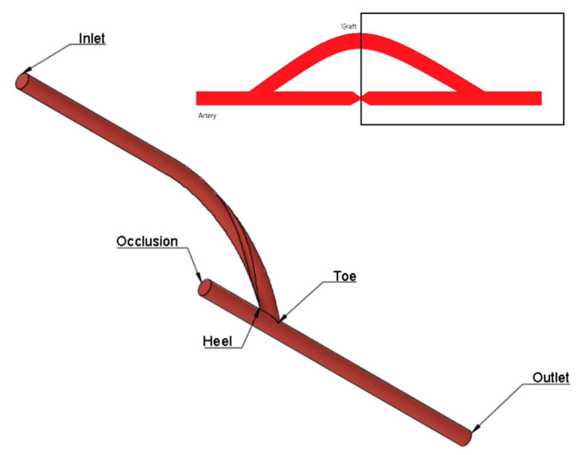
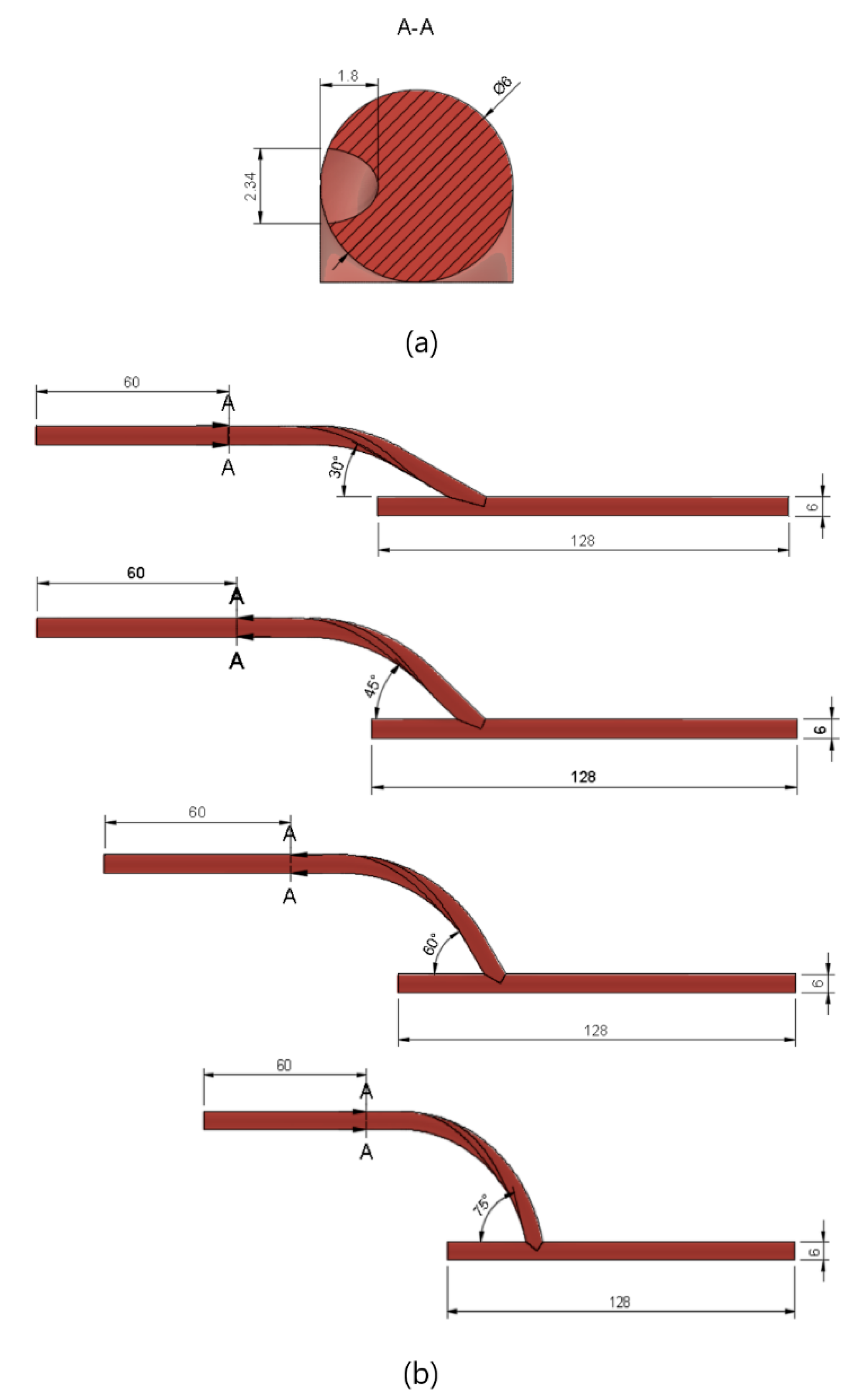
2.1. Geometry

Geometries were generated using the computer-aided drawing (CAD) software Autodesk Fusion 360 v.2.0.13881. All geometries consist of an end-to-side anastomosis between the bypass graft and an idealized model of the femoral artery. The ratio of the graft diameter to the arterial diameter was set to one. A conceptual model of geometries used is shown in Figure 1.
In the first part of the study, geometries of spiral flow graft with varying anastomosis angles were generated. The spiral flow was induced by incorporating a semi-elliptical ridge (3.157 mm2) that revolved once around the length of the entire graft. At the inlet, the ridge is oriented 180° from the standard axis. The cross-sectional profile of the graft, as in Figure 2a, was taken entirely from the reference study [24]. The bypass graft was attached to the host artery at angles of 15° increments from 30° to 75°. To ensure that the flows into and out of the grafts were fully developed, sufficient entry and exit lengths were added upstream and downstream of the grafts, respectively, as seen in Figure 2b.
In the second part of the study, the performance of the optimized spiral graft was compared with that of a conventional non-spiral graft. For the non-spiral graft model, a hollow cylindrical tube (6 mm in diameter) without a ridge was used as the graft. The conventional and the ridged grafts were both connected to the host artery with the same anastomosis angle as that optimized in the first part of the study.

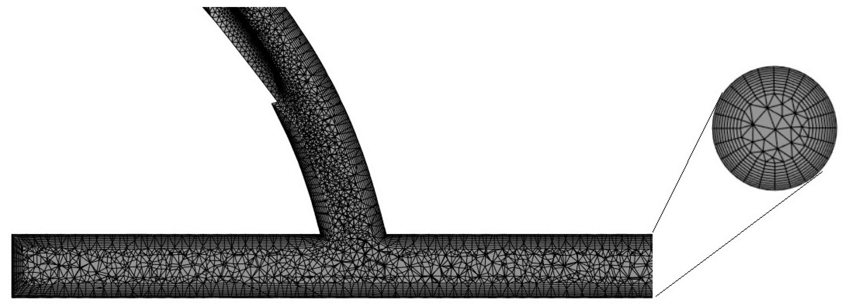
2.2. Mesh Generation

Using the ANSYS mesh generation software, a hybrid mesh was generated. Tetrahedral elements were used for the core regions while regular, prismatic elements were used near the walls to better capture the characteristics of the boundary layer, as seen in Figure 3. The number of elements was limited to 512,000 due to license limits. The orthogonal quality of the mesh was greater than 0.10 at all times to ensure a good quality mesh for the simulations.

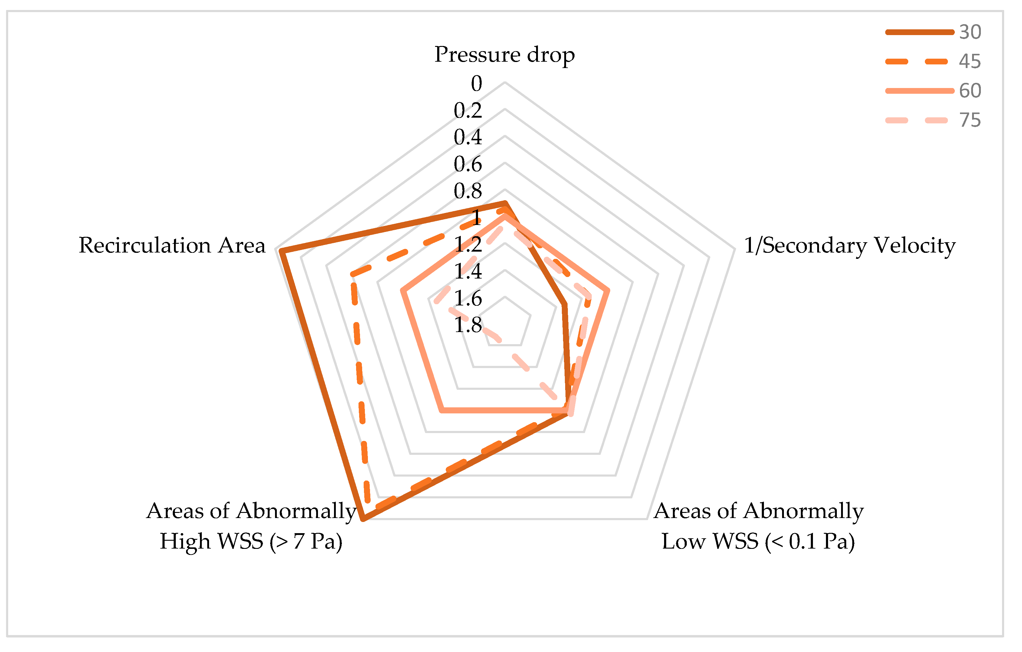
2.3. Determination of the Optimal Anastomosis Angle

Steady-state CFD analysis was performed to evaluate the effects of the anastomosis angle on the hemodynamics in the distal region of the ridged-graft-to-artery anastomosis. The fluid material was blood. It was set to have a constant density of 1050 kg/m3, and its shear-thinning properties were considered by describing the viscosity using the Carreau model (time constant = 3.313 s; power-law index = 0.3568; zero-shear viscosity = 0.056 kg m−1 s−1; infinite shear viscosity = 0.0035 kg m−1 s−1). The flow was set to be laminar, and heat transfer effects were ignored. A constant, uniform velocity of 0.317 m/s and zero pressure were imposed on the inlet and outlet, respectively. Rigid wall and non-slip assumptions were used for the walls [24].
ANSYS-Fluent 2022 R1 Student Version was used to solve the CFD problem. Convergence was ensured by reducing the continuity and velocity residuals to 10−6, monitoring the overall mass balance, and waiting for the outlet velocity value to approach a constant value with further iterations.
The best anastomosis angle was decided by the comparison of pressure drop values, secondary velocity magnitudes, and areas affected by recirculation and abnormal wall shear stress (WSS) values. An increase in the secondary velocity magnitude and a decrease in all other variables would indicate improved graft performance [24].

2.4. Comparison of Performance between a Conventional Graft and Spiral-Flow-Inducing Graft

The performance of the angle-optimized graft was compared with that of a non-spiral graft using transient CFD analysis. In setting up the CFD problem, the same mesh and material properties used in the steady-state analysis were used. For the initial boundary condition, a pulsatile blood flow was imposed using a periodic velocity waveform based on magnetic resonance (MRI) readings in the femoral artery of healthy subjects, as seen from the waveform in Figure 4 [31]. Similar to the steady-state simulations, a zero-pressure boundary condition was used for the outlet, and rigid and no-slip conditions were imposed on the walls of the models [24].
As for the solver, the SIMPLE algorithm was used. The time step size was set to 0.009 s with a maximum of 25 iterations per time step. The convergence threshold was set to 10−6. To avoid instabilities, the simulation was run for five periods, and results were extracted from the final cycle.

3. Results

3.1. Optimization of Anastomosis Angle

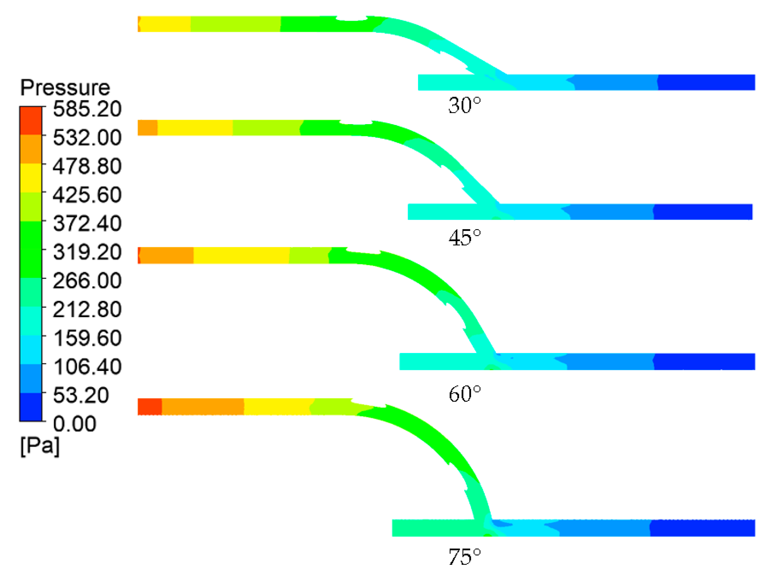
3.1.1. Pressure Drop

The human vascular system, just like any other fluid flow system, evolves to reduce flow resistance and induce fluid flow [32]. It is therefore expected for blood to flow with low resistance, thus reducing the pumping power required of the heart to circulate the fluid throughout the body. The amount of resistance is indicated by the total pressure drop between the inlet and the outlet. It represents the amount of friction, static, and acceleration pressure drops experienced by the fluid between two points [33]. Small pressure drops indicate lesser fluid flow resistance, so it must be sought when designing a bypass graft.
Looking at the pressure contour on the longitudinal section of the geometric model shown in Figure 5, it can easily be seen that the anastomosis angle heavily influenced the pressure distribution of the flow. Much of the difference between the four models can be observed in the entry length to the graft. A greater pressure reduction in this area was observed with the larger anastomosis angles. In essence, this indicates that larger anastomosis angles result in higher inflow resistance in bypass grafts.
In addition to this, another notable difference is the area around the anastomosis toe. The anastomoses with larger angles had higher pressure gradients within these regions as evidenced by lower pressure (bluer) areas on the anastomosis toe. This could be explained if we consider the anastomosis to be a pipe bend configuration. At the bend (anastomosis), the flow direction changed. At the bend exit, due to inertia, centrifugal force caused the fluid to migrate toward the outer curve or extrados (host artery bed) and away from the intrados (anastomosis toe), explaining the relatively lower pressure values at the upper region of the host artery compared to the lower region within the anastomosis region [34,35].
The results presented in Table 1 show a positive relationship between the anastomosis angle and pressure drop. The pressure drop increased by about 5–6% per an increase of 15° in the anastomosis angle. This is congruent with findings in the literature, indicating the benefit of smaller anastomosis angles in bypass graft performance through the reduction of the pressure drop [8,36,37].

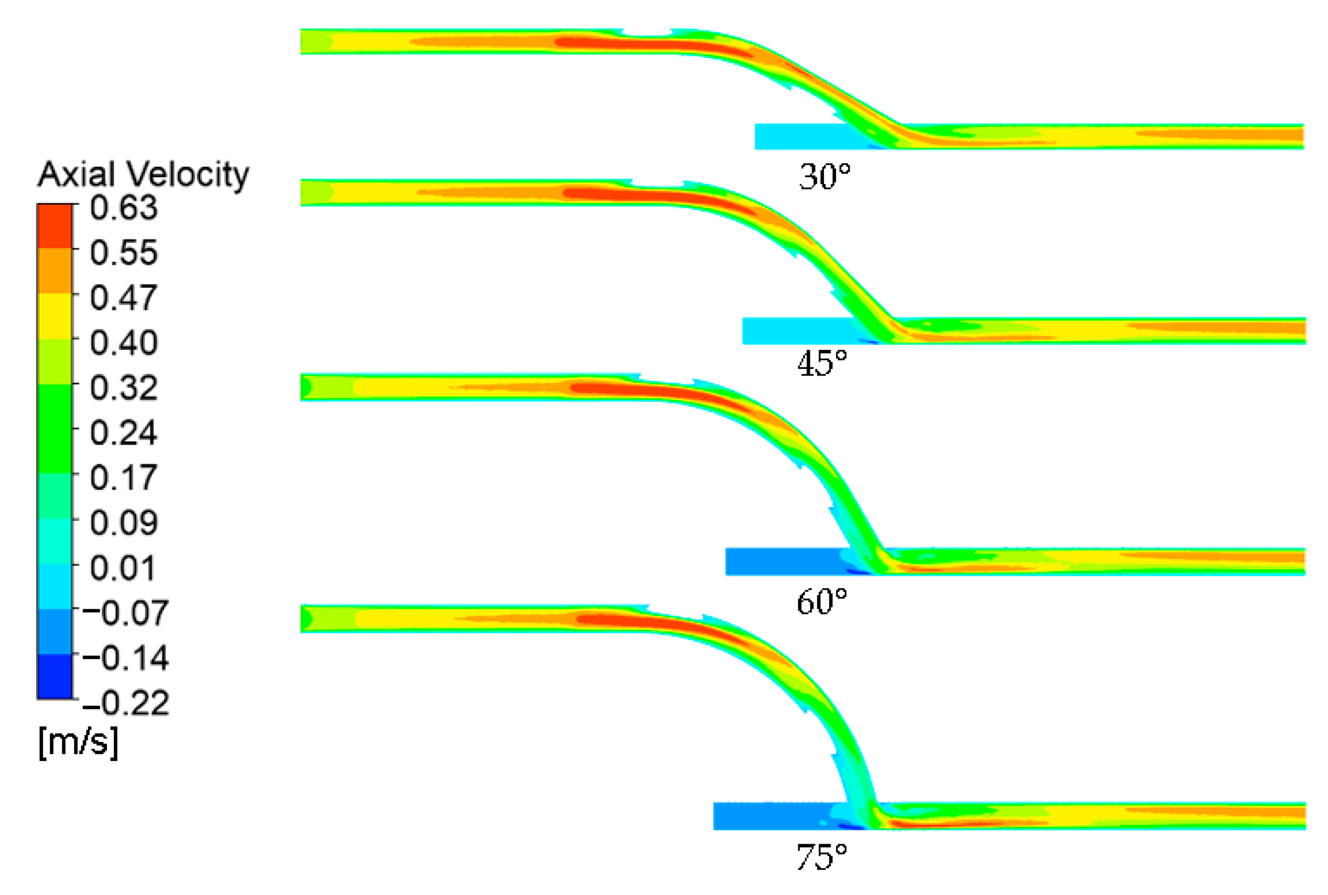
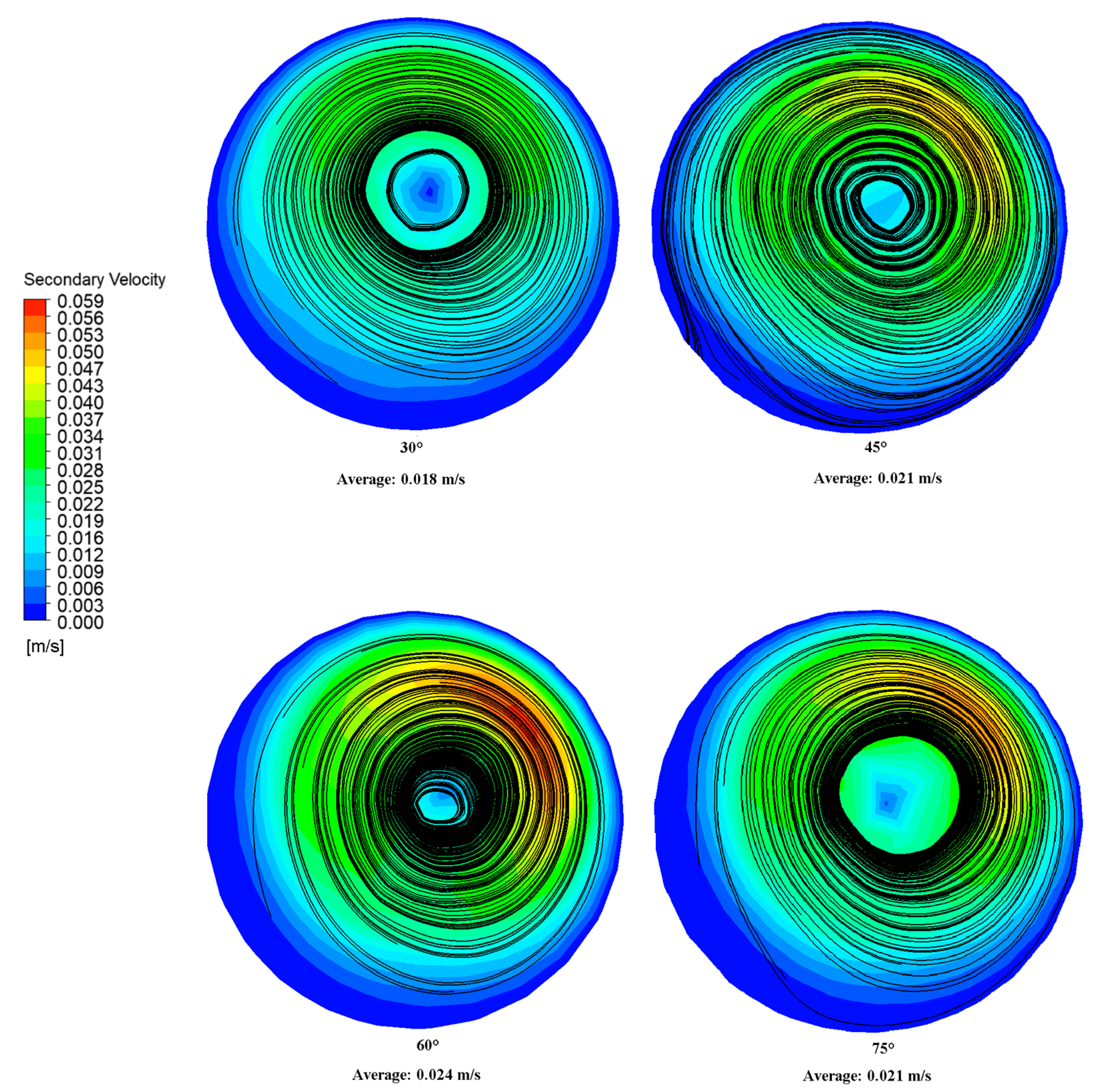
3.1.2. Axial Velocity and Secondary Velocity

The axial velocity profiles across the longitudinal section of the model across different anastomosis angles are shown in Figure 6. Linking the discussion to the pressure distributions observed, the velocity profile supported the idea of greater inflow resistance in larger anastomosis angles. At lower anastomosis angles, the flow achieved a faster velocity (orange) much earlier in the entry graft length compared to larger anastomosis angles, indicating less resistance to flow. The jump from orange to red values signified the graft inlet where the area was reduced due to the presence of the ridge, so the velocity increased based on the continuity equation.
Following the pipe bend analogy, similar observations can be made regarding the velocity profile in the anastomosis region as those relating to the pressure profile. The flow separation observed in the pressure field was confirmed by the velocity profile, showing higher velocities at the host artery bed and a dead zone in the anastomosis toe. Likewise, the same relationship between the anastomosis angle and velocity gradient was observed where a larger anastomosis angle resulted in higher velocity gradients.
Furthermore, the axial velocity contours prove that spiral flow has indeed been developed as a result of the internal ridge within the graft. At the anastomosis, the blood flow shifted toward the artery bed, as indicated by the high-velocity region in the lower portion of the artery immediately after the anastomosis. Due to inertia, the flow was expected to stay within this region if the flow had been straight [34]. Looking further downstream, near the model outlet, the high axial velocity regions had instead shifted toward the upper region of the artery, which is only possible if the flow is spiral.
Secondary velocity refers to the swirling characteristics of flow, consisting of the radial and tangential velocity components. Its magnitude is calculated using Equation (1).
v s e c o n d a r y = v r a d i a l 2 + v t a n g e n t i a l 2
A higher secondary velocity indicates the presence of greater spirality in flow, so it is expected to impart benefits to blood flow through higher, atheroprotective WSS and reduction in stagnation, recirculation, and turbulence [14,15,16,17].
Figure 7 shows the secondary velocity contours and crossflow streamlines 50 mm from the anastomosis toe. The contours indicate the magnitude of the secondary velocity. Because of the spirality of flow, the overall bulk fluid motion was shifted from the center toward the upper region of the artery, causing asymmetry. This is consistent with the higher axial velocity regions in the upper region of the artery observed near the model outlet in Figure 6. This flow asymmetry brought the bulk motion nearer to the walls, allowing higher shear stress to be developed [25]. However, it is worth noting that compared to the axial velocity, the magnitude of the secondary velocity was much smaller.
Meanwhile, the black lines in Figure 7 represent the surface streamline. This represents the paths through which zero particle masses would pass, and it is calculated using the Runge–Kutta method of vector variable integration [38]. Consistent with the secondary velocity profile, the cores of the surface streamlines were shifted toward the upper artery region. Single dominant spiral flows were observed in the 45°, 60°, and 75° grafts. Meanwhile, two concentric spiral flows, associated with significantly lower secondary velocity magnitudes, were observed for the 30° graft. Because not all of the spiral flow character was directed in the artery walls (due to some spiral character being lost in the inner spiral flow), a weaker swirling motion was experienced by the artery walls, reducing the shear forces and friction generated on the walls. This could explain the lower WSS pressure drop observed for the 30° graft relative to higher anastomosis angles [39].

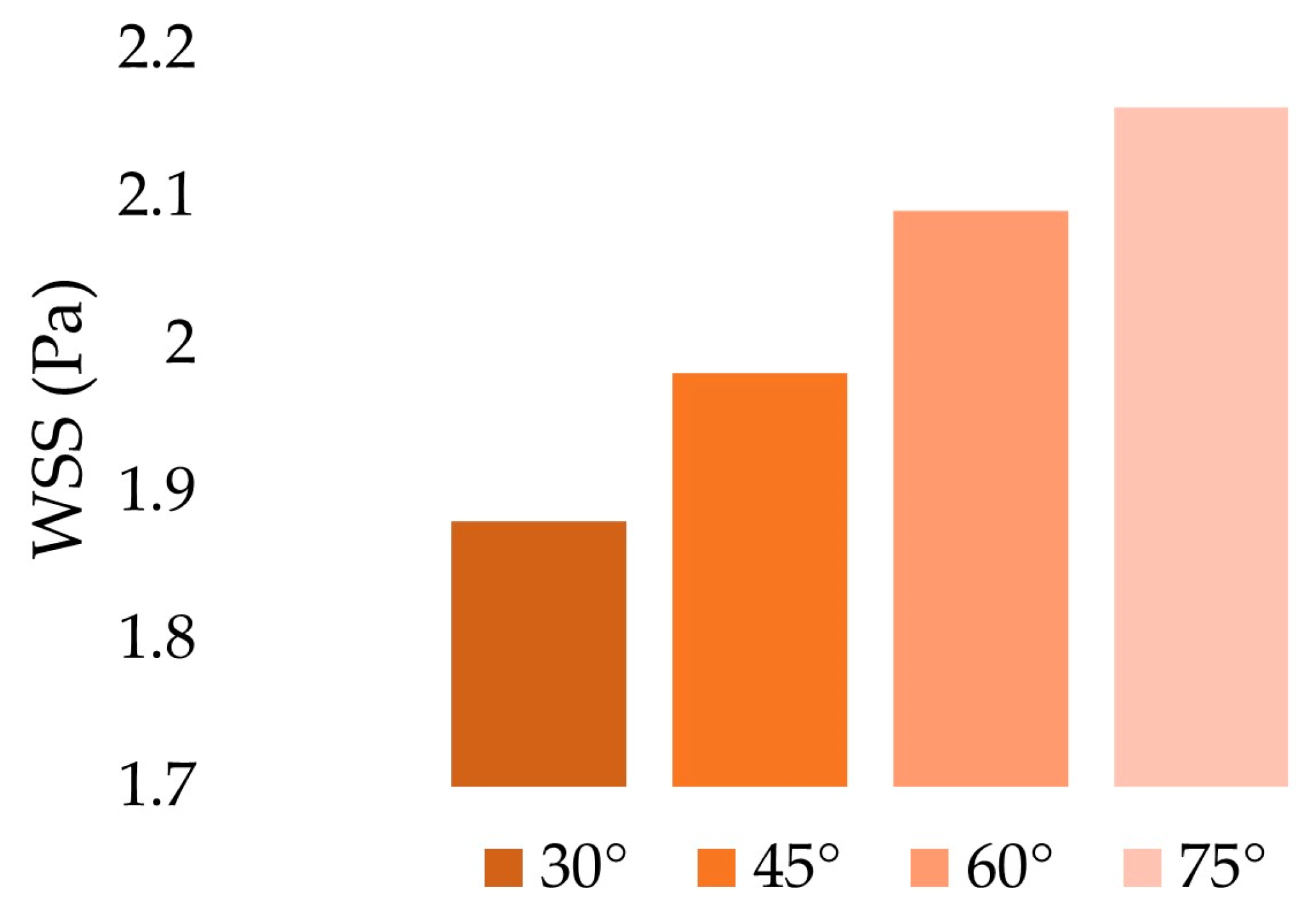
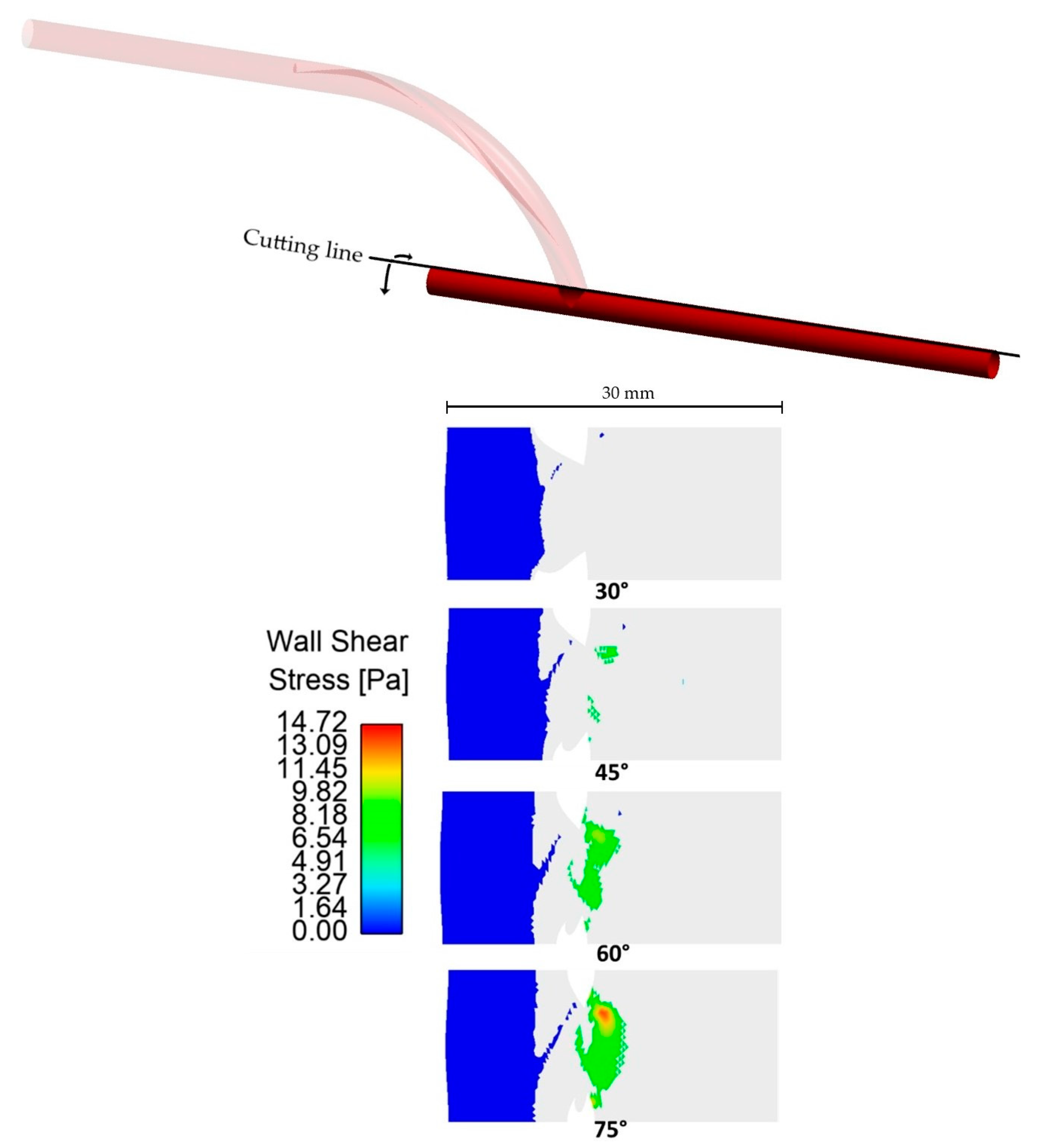
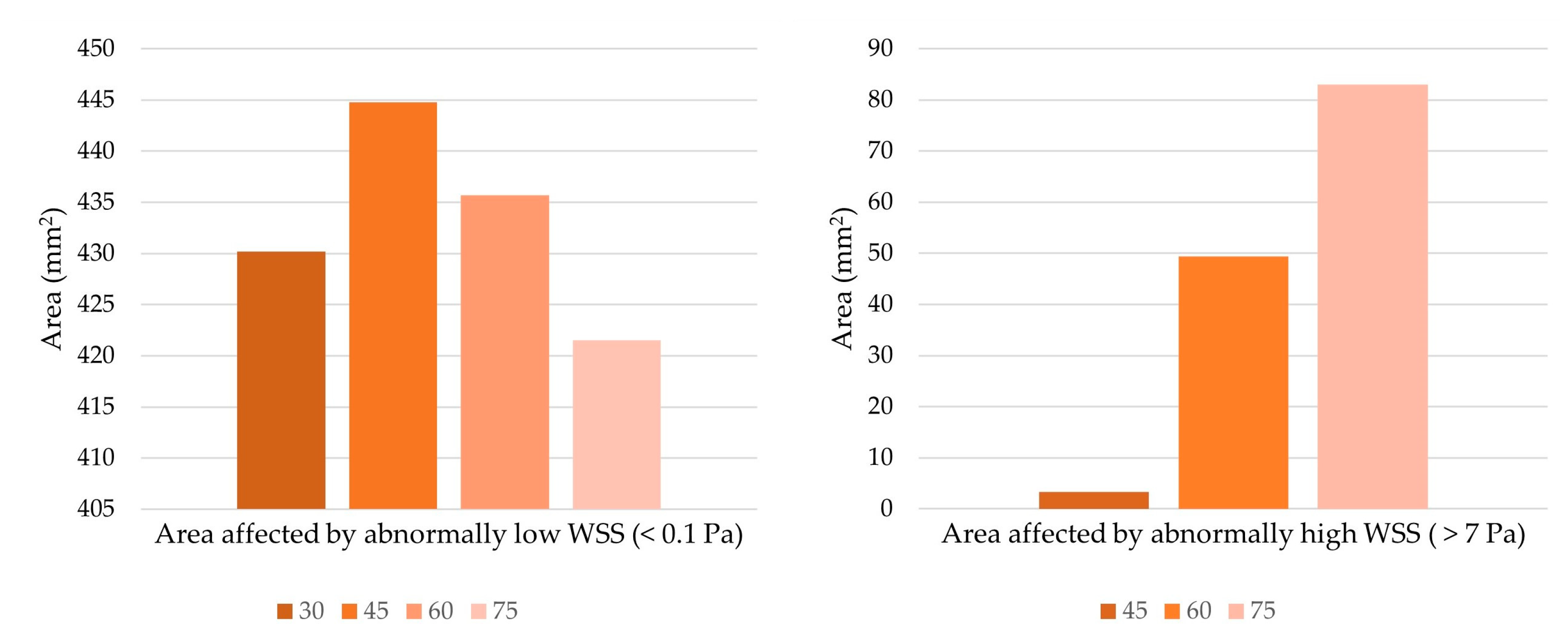
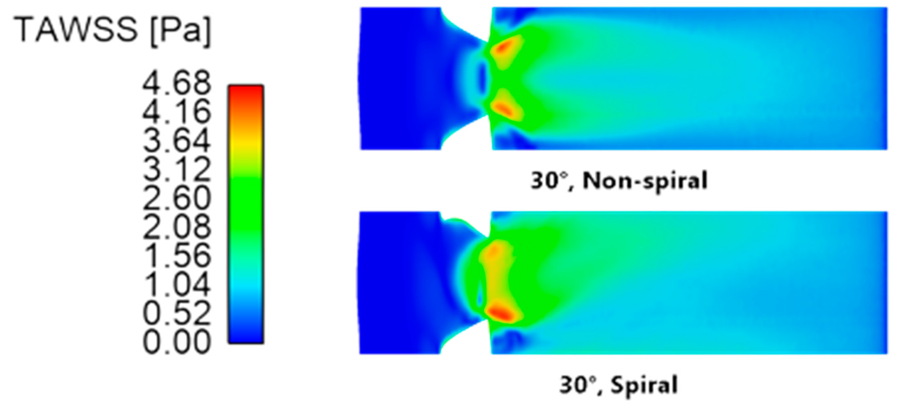
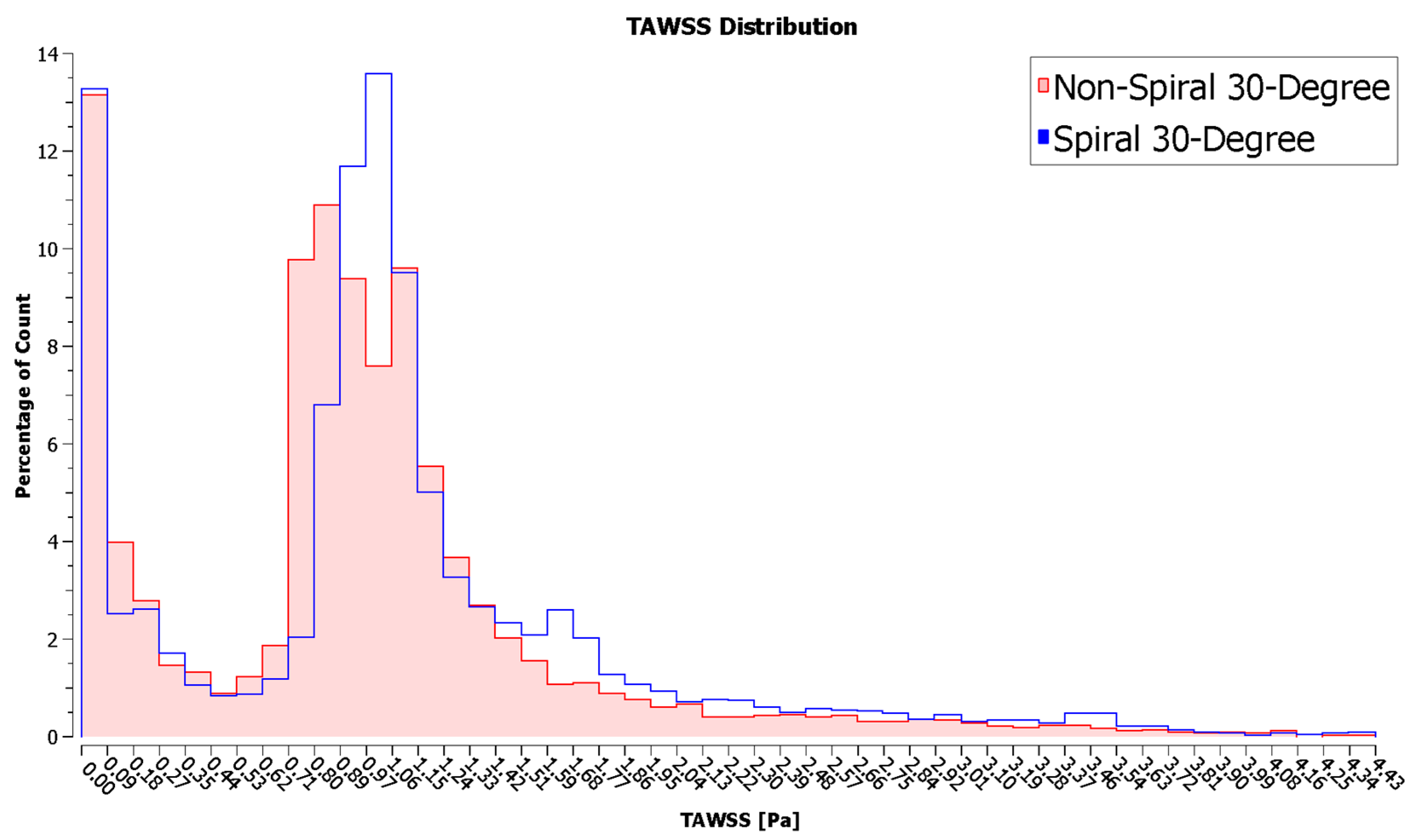
3.1.3. Wall Shear Stress

Wall shear stress (WSS) is the measure of the force exerted by a fluid motion on a solid boundary and vice versa toward the direction of the local tangent plane. The amount of shear stress generated on blood vessel walls is critical for endothelial homeostasis, so WSS is viewed as an essential predictor or indicator of cardiovascular diseases [40].
Despite the consensus that WSS is important for endothelial homeostasis, two opposing claims exist about the optimal WSS for bypass grafts. One hypothesis claims that high WSS must be sought because low WSS values cause stenosis due to the intimal thickening of vessel walls and occlusion of the blood vessel lumen due to plaque formation [3,41]. Meanwhile, the other hypothesis suggests that higher WSS may have detrimental effects on bypass graft performance as it is linked to endothelial damage that can result in thrombosis and lesions [4,5,6], and possibly, intimal thickening as well [7]. To avoid these complications, we optimized the anastomosis angle of the bypass grafts by selecting the angle that would yield WSS values that are closer to normal, physiological WSS levels (0.1–7 Pa) [8,9].
Figure 8 shows the spatial average of WSS according to the anastomosis angle. The values reported were computed over the whole wall of the host artery. The results indicated a positive linear relationship between the anastomosis angle and the spatial average values of WSS (r2 = 0.9923). This relationship may be explained by both the bulk motion and the secondary flow components of the fluid. As observed in the axial velocity contour maps (Figure 6), higher axial velocities near the walls and higher velocity gradients were observed for larger anastomosis angles which translate to increased shear stress [42]. Furthermore, the swirl motion represented by the secondary velocity also generated higher shear stress in the artery walls due to the tangential velocity vector [39]. This seemed to suggest that increasing the anastomosis angle between the graft and artery may have the beneficial effect of reducing the tendency of the graft to induce intimal thickening by increasing the WSS. However, this presented a problem wherein an increased anastomosis angle resulted in the development of pathologically high WSS.
The colored areas in Figure 9 show the regions of the unrolled artery affected by pathologically high and low WSS. These areas were only located near the anastomosis region. Hence, only pertinent regions were shown instead of the entire length of the host artery. Significant effects were observed when looking at the relationship between the anastomosis angle and areas with abnormally high WSS (>7 Pa). The areas affected by abnormally high WSS were situated in the region of the artery that directly receives blood flow from the graft outlet. Based on the axial velocity profile, upon flow separation, high-velocity fluid streams were accelerated by centrifugal force toward this region, justifying why they were exclusively found in this area. In Figure 10, large decreases in areas of abnormally high WSS were observed whenever the anastomosis angle was decreased, even being completely eliminated at a 30° angle, suggesting the effectiveness of using smaller anastomosis angles.
The anastomosis angle seems to have no significant effects when looking at areas affected by pathologically low WSS. The smallest and largest areas affected by pathologically low WSS had a percentage difference of only 5.3%, so no significant improvement would be observed whichever angle is used. Moreover, the areas affected by pathologically low shear stresses were located in the bypassed region where little to no blood is expected to flow. Improvement within this area is of little use in optimizing the performance of bypass grafts.

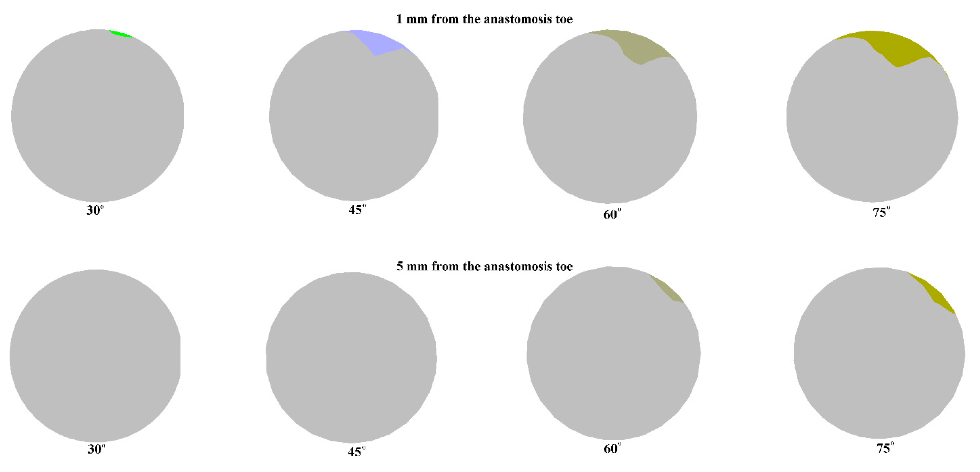
3.1.4. Recirculation

The presence of recirculation is associated with the development and progression of cardiovascular diseases. Due to flow stagnation caused by recirculating flow, substances found in the blood can easily adhere to and accumulate on blood vessel walls. As such, recirculation is linked to atherosclerosis, thrombosis, endothelial damage, as well as intimal thickening [43,44,45,46,47]. The optimal graft design must therefore be able to induce blood flow with minimal recirculation regions.
Figure 11 shows the areas affected by recirculation (negative axial velocity), as seen in the cross-section of the artery one millimeter and five millimeters away from the anastomosis toe. Recirculation regions were found in the upper regions of the artery. This is in line with the flow separation in the pressure and axial velocity contours, and it corresponds to the dead zone observed in the region. Since the centrifugal force due to inertia shifted the bulk motion outwards toward the host artery bed, a low-velocity region formed within the toe region that allowed for recirculation.
The size of recirculation is influenced by the anastomosis angle as higher anastomosis angles tend to have larger recirculation regions. This was observed in the two monitoring planes. Of particular interest is the total elimination of recirculation in the second monitoring plane at lower anastomosis angles. This size dependence of the area of recirculation on the anastomosis angle is also consistent with the pressure and velocity contours observed for the models.
The location of recirculation regions and the dependence of their size on the anastomosis angle is consistent with findings in the literature [26,48,49], indicating the advantage of smaller anastomosis angles in bypass graft design through the minimization of recirculation regions.

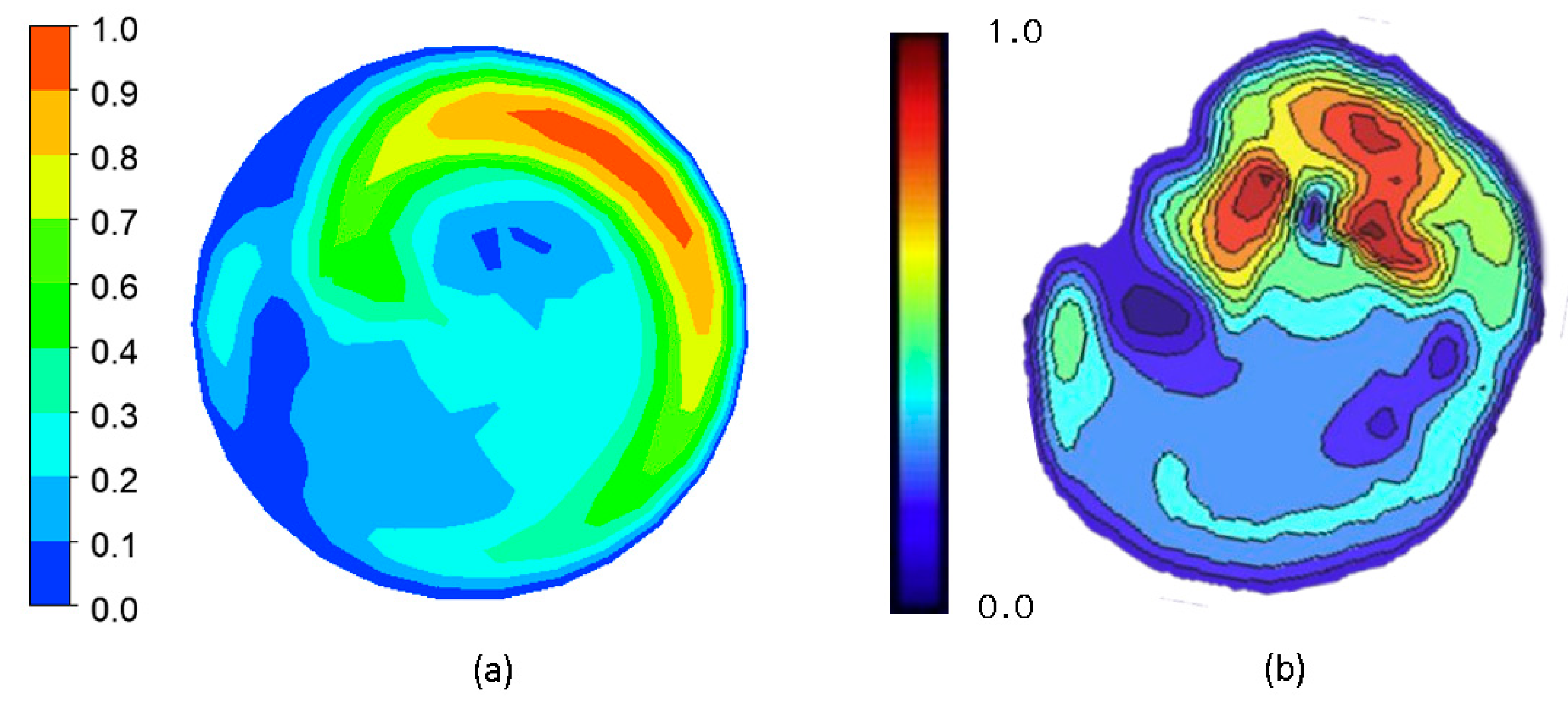
3.2. Data Validation

To validate the results of the simulation, we compared the results obtained with the simulation to data available in the literature. A qualitative comparison was performed by comparing the result of the steady-state, 60° graft simulation in Figure 12a against the measurements of Kokkalis et al. in an in vitro study characterizing the secondary flow characteristics of a ridged graft design using vector Doppler imaging, as seen in Figure 12b [50]. The secondary velocity profile of the present study was quite similar to that observed in an actual experiment. Regions of high and low secondary velocity magnitudes from the imaging procedure were successfully replicated in the present study.
To further confirm the validity of the results, a quantitative comparison was also performed. The pressure drop, secondary velocity, WSS, and recirculation values calculated from the steady-state simulation of the 60° ridged graft were compared to the results obtained in the reference study [24]. Table 2 summarizes these data.
In four out of five variables observed, the percentage difference between the reference and calculated data was reasonably low. However, of note is the percentage difference between the area affected by recirculation at Plane 2 of the previous and present studies. The data from the literature are significantly higher than the calculated value which may seem to invalidate the results of the present study. However, it must be noted that these two data sets did not come from the same, exact geometry. The reference study did not present the result for the steady-state simulation for their optimal design (one elliptical ridge, oriented at 180°). Only the simulation result for a graft with one circular ridge oriented at 180° was available for comparison. Their data showed that while keeping other variables fairly equal, the use of a tall, elliptical ridge significantly reduced the extent of recirculation at the second monitoring plane located 5 mm from the anastomosis toe compared with the use of a circular ridge [24]. This could be explained by the increased secondary velocity caused by the elliptical ridge. Zhang et al. had shown that swirling flow creates a sweeping washout effect that effectively reduces wall collisions and, in turn, both stasis and retrograde flow [15]. The increased secondary velocity of the elliptical ridge must have enhanced the washout characteristics in the outflow, thereby reducing the area affected by recirculation. This, with its possible synergistic effect with other optimized design parameters, may explain the huge difference between the recirculation percentage in the second monitoring plane despite close values for other variables.

4. Discussion

The failure of bypass grafts used in the treatment of atherosclerosis is often attributed to poor hemodynamics in affected areas. Since hemodynamics is heavily influenced by the geometry of the vessels, efforts have been made to discover the optimal geometry for improved bypass graft performance. One such effort was undertaken by the team of Ruiz-Soler et al. who designed a ridged, spiral-flow-inducing bypass graft under the assumption that swirling flow imparts atheroprotective mechanisms [24]. We sought to enhance the findings of their team by changing two factors in their methodologies. First, we evaluated how changing the anastomosis angle could affect the performance of their ridged graft design which was optimized only for a 60-degree anastomosis angle. This is motivated by numerous studies highlighting the huge influence of the anastomosis angle in local flow fields in the vicinity of an anastomosis. Second, whereas Ruiz-Soler and their team optimized their design based on the assumption that high WSS values are more favorable to bypass graft performance, we performed our optimization based on the assumption that WSS values within the normal physiologic range are favorable to bypass graft performance since extremely high WSS may induce thrombosis and endothelial damage [4,5,6].

4.1. Optimal Anastomosis Angle

The results show that local hemodynamics in the anastomosis region is heavily influenced by the anastomosis angle, so optimizing the angle is a potential strategy for improving bypass graft patency. The optimal design must display reduced pressure drops, smaller recirculation regions, and minimized areas affected by abnormally high or low WSS. Suggestions from the literature also indicate the potential benefits of spiral flow, so higher secondary velocity magnitudes could indicate better bypass graft performance.
Figure 13 summarizes the results observed for the pressure drop, secondary velocity, recirculation area, and areas of abnormally high and low WSS according to anastomosis angle. The values were normalized to the 60° graft values. The chart was arranged so that more favorable values were projected outwards; thus, the optimal graft would occupy the largest area in the chart.
The 30° graft outperformed the other grafts on three variables. Significant reduction in areas of recirculation and abnormally high WSS resulted from using a 30° anastomosis angle. The pressure drop between the inlet and outlet was also slightly reduced when using the smallest angle. In these variables, clear, negative relationships between the angle and graft performance were observed.
Looking at the areas affected by abnormally low WSS, the 30° graft was slightly outperformed by the 60° graft. However, as previously discussed, any improvement based on this variable may not be important due to the minuscule difference between the highest and smallest values observed and because little to no blood flow is expected in these areas anyway.
Lastly, the 30° graft fared the worst in terms of flow spirality, as indicated by the secondary velocity magnitude. However, it must be noted that the secondary velocity does not directly indicate superior graft performance. It is just suggested to enhance other hemodynamic metrics such as WSS, so although the 30° graft had the weakest spiral character, no direct detrimental biological effects arose from it. Increased spiral character, even if it raised WSS as observed from other anastomosis angles, may have hurt graft performance due to increased pressure drop and larger areas affected by abnormally high WSS.
Therefore, the use of smaller anastomosis angles seemed to have enhanced the hemodynamic performance of ridged, spiral-flow-inducing graft design. This is congruent with studies in the literature which state that smaller anastomosis angles are beneficial to bypass graft performance. This benefit is often attributed to less “disturbed flow” caused by smaller anastomosis angles which are characterized by reduced WSS peaks and gradients, flow separation, recirculation area, and secondary flow components [47].

4.2. Comparison of Spiral-Flow-Inducing Graft Design vs. Conventional Graft Design

To assess whether the inducement of spiral flow was beneficial to graft performance, a subsequent transient simulation was performed to compare the performance of the 30° graft with and without an internal ridge. The TAWSS was used as a basis for comparison between the two configurations. TAWSS is the temporal average of WSS in a single cardiac cycle [51].
Figure 14 shows the TAWSS contours of the host artery that has been grafted at a 30° anastomosis angle using non-spiral and spiral configurations. A qualitative analysis of the two models shows two prominent differences between the non-spiral and spiral flow. First, it can be seen that a conventional, non-spiral graft resulted in a symmetric TAWSS profile that extended distally from the anastomosis toe, whereas a ridged, spiral-flow-inducing graft resulted in an asymmetric one. This agreed with the findings of Ruiz-Soler et al. [24,25], showing that a ridged graft design resulted in an asymmetric TAWSS contour due to the bulk swirling motion in the host artery. Another noticeable difference lies in the region where the blood flow from the graft directly impinged the artery bed. In the non-spiral configuration of the graft, the said region was characterized by low TAWSS. Meanwhile, in the spiral graft configuration, elevated TAWSS was observed on the region, extending proximally from the anastomosis toe toward the occlusion. Closer inspection also shows higher TAWSS along the suture line of the anastomosis. This may also be explained by the fluid dynamics within bends where the change in fluid direction causes the fluid to shift toward the extrados due to inertial centrifugal forces. As such, the blood flow shifts toward the host artery bed where the bulk fluid motion and secondary flow components caused the generation of higher shear stresses.
Quantitatively speaking, the spiral configuration resulted in higher TAWSS. Table 3 compares the maximum and area average values of TAWSS. The values were averaged across the entire length of the host artery. The non-spiral graft yielded a higher maximum TAWSS value, but its difference from the maximum value of the spiral configuration was practically negligible. On the contrary, the spiral configuration resulted in a higher TAWSS area average than that of its counterpart. In support of this, Figure 15 shows the percentage count of elements in the model according to the TAWSS value. As can be seen, a larger area of the artery was covered with elevated TAWSS when the spiral graft configuration was used. Conversely, at lower TAWSS, the non-spiral graft configuration had higher counts.
Low TAWSS is associated with the development and progression of intimal hyperplasia. McGah et al. performed a longitudinal study to observe hemodynamic values on implanted femoral bypass grafts. Through combined ultrasound imaging and CFD processes, they correlated regions of stenosis with low TAWSS [52]. Similarly, Jackson et al. linked low values of computed TAWSS to increased intimal thickening on lower limb venous bypass grafts measured through ultrasound imaging [53]. As previously described, low shear stresses acting on endothelial cells prevent the inhibitory effects of the nitric oxide signaling pathway against smooth muscle cells and increase the presence of low-density lipoproteins, macrophages, and adhesion molecules in affected areas. These reasons may explain why low TAWSS causes graft stenosis [3,41].
The use of the internal ridge to induce spiral flow in the blood may therefore enhance graft patency and longevity by raising TAWSS. The ability of spiral-flow-inducing grafts to raise TAWSS has been documented by several computational studies [23,25,54,55]. A study by El Sayed et al. further confirmed the effectiveness of spiral flow in increasing the patency rates of arteriovenous grafts in vivo [18].

5. Conclusions

In this paper, we aimed to address bypass graft failures by minimizing hemodynamic disturbances through the investigation and optimization of anastomosis angles for ridged spiral flow bypass grafts. We hypothesized that due to the significant influence of the junction angle in local flow fields within the anastomosis region, it can largely affect blood flow, and optimizing it could provide a synergistic effect with the spiral flow in stabilizing local hemodynamics. Through CFD, we were able to determine that the anastomosis angle indeed heavily influences the local hemodynamics in bypass graft anastomosis and thus can be used in enhancing bypass graft patency and longevity. Primarily, we observed that smaller anastomosis angles tend to minimize hemodynamic disturbances associated with ridged spiral flow grafts. The smaller anastomosis angle minimized the pressure drop and areas affected by recirculation and abnormally high WSS, all of which are believed to cause bypass graft failure. This fills the research gap on how the anastomosis angle can play a role in the hemodynamic performance of ridged spiral flow grafts. Additionally, we have confirmed that the use of spiral flow bypass grafts can outperform conventional, straight flow bypass grafts as they can offer higher, atheroprotective shear conditions. Our study demonstrates how important optimizing and understanding the relationship among different geometric properties are in designing long-lasting bypass grafts. Future studies in bypass graft designs must therefore ensure that each geometric property is optimized individually and with respect to its relationship to other properties.
Several simplifying assumptions were used to reduce the complexity and computational cost of solving the problem. Geometries were idealized, so future studies may include imperfections in their geometric models, or if computational resources permit, use more accurate imaging and patient-specific models. The study did not include the proximal anastomosis region in the analysis, so it can be looked into in future research. Fluid–structure interaction (FSI) analysis may be used in future iterations to take into consideration the reciprocal effects of hemodynamics and vessel wall deformation which were neglected in this study.

Author Contributions

Conceptualization, J.J.A., L.T. and J.H.; formal analysis, J.J.A.; funding acquisition, L.T.; investigation, J.J.A.; methodology, J.J.A., L.T. and J.H.; software, J.J.A.; supervision, L.T. and J.H.; validation, J.J.A.; visualization, J.J.A.; writing—original draft, J.J.A.; writing—review and editing, J.J.A., L.T. and J.H. All authors have read and agreed to the published version of the manuscript.

Funding

This study was published through a grant provided by Mapúa University.

Data Availability Statement

The data presented in this study are available in the article.

Conflicts of Interest

The authors declare no conflict of interest.

References

  1. Aaronson, P.I.; Ward, J.T.; Connolly, M.J. The Cardiovascular System at a Glance, 4th ed.; Wiley-Blackwell: Hoboken, NJ, USA, 2012. [Google Scholar]
  2. Pashneh-Tala, S.; MacNeil, S.; Claeyssens, F. The Tissue-Engineered Vascular Graft—Past, Present, and Future. Tissue Eng. Part B Rev. 2016, 22, 68–100. [Google Scholar] [CrossRef] [PubMed] [Green Version]
  3. Braga, S.F.; Neves, J.R.; Ferreira, J.; Carrilho, C.; Simões, J.C.; Mesquita, A. Neointimal Hyperplasia. Port. J. Card. Thorac. Vasc. Surg. 2021, 26, 213–217. [Google Scholar] [CrossRef]
  4. Binns, R.L.; Ku, D.N.; Stewart, M.T.; Ansley, J.P.; Coyle, K.A. Optimal graft diameter: Effect of wall shear stress on vascular healing. J. Vasc. Surg. 1989, 10, 326–337. [Google Scholar] [CrossRef] [PubMed] [Green Version]
  5. Hathcock, J.J. Flow Effects on Coagulation and Thrombosis. Arter. Thromb. Vasc. Biol. 2006, 26, 1729–1737. [Google Scholar] [CrossRef]
  6. Malek, A.M.; Alper, S.L.; Izumo, S. Hemodynamic Shear Stress and Its Role in Atherosclerosis. JAMA 1999, 282, 2035–2042. [Google Scholar] [CrossRef]
  7. Malik, J.; Tuka, V.; Tesař, V. Local Hemodynamics of the Vascular Access for Hemodialysis. Kidney Blood Press. Res. 2009, 32, 59–66. [Google Scholar] [CrossRef]
  8. Totorean, A.F.; Bernad, S.I.; Hudrea, I.C.; Susan-Resiga, R.F. Competitive flow and anastomosis angle influence on bypass hemodynamics in unsteady flow conditions. AIP Conf. Proc. 2017, 1863, 030013. [Google Scholar] [CrossRef]
  9. Quicken, S.; de Bruin, Y.; Mees, B.; Tordoir, J.; Delhaas, T.; Huberts, W. Computational study on the haemodynamic and mechanical performance of electrospun polyurethane dialysis grafts. Biomech. Model. Mechanobiol. 2020, 19, 713–722. [Google Scholar] [CrossRef] [Green Version]
  10. Giuliano, L.V.; Buffo, A.; Vanni, M.; Frungieri, G. Micromechanics and strength of agglomerates produced by spray drying. JCIS Open 2023, 9, 100068. [Google Scholar] [CrossRef]
  11. Giuliano, L.V.; Buffo, A.; Vanni, M.; Lanotte, A.S.; Arima, V.; Bianco, M.; Baldassarre, F.; Frungieri, G. Response of shear-activated nanotherapeutic particles in a clot-obstructed blood vessel by CFD-DEM simulations. Can. J. Chem. Eng. 2022, 100, 3562–3574. [Google Scholar] [CrossRef]
  12. Ma, P.; Lai, X.; Luo, Z.; Chen, Y.; Loh, X.J.; Ye, E.; Li, Z.; Wu, C.; Wu, Y.-L. Recent advances in mechanical force-responsive drug delivery systems. Nanoscale Adv. 2022, 4, 3462–3478. [Google Scholar] [CrossRef] [PubMed]
  13. Houston, J.G.; Gandy, S.J.; Sheppard, D.G.; Dick, J.B.; Belch, J.J.; Stonebridge, P.A. Two-dimensional flow quantitative MRI of aortic arch blood flow patterns: Effect of age, sex, and presence of carotid atheromatous disease on prevalence of spiral blood flow. J. Magn. Reson. Imaging 2003, 18, 169–174. [Google Scholar] [CrossRef] [PubMed]
  14. Baratchi, S.; Chen, Y.-C.; Peter, K. Helical flow: A means to identify unstable plaques and a new direction for the design of vascular grafts and stents. Atherosclerosis 2020, 300, 34–36. [Google Scholar] [CrossRef] [PubMed]
  15. Zhang, P.H.; Tkatch, C.; Newman, R.; Grimme, W.; Vainchtein, D.; Kresh, J.Y. The mechanics of spiral flow: Enhanced washout and transport. Artif. Organs 2019, 43, 1144–1153. [Google Scholar] [CrossRef] [PubMed]
  16. Moshfegh, A.; Javadzadegan, A.; Zhang, Z.; Afrouzi, H.H.; Omidi, M. Effect of aortic spiral blood flow on wall shear stress in stenosed left main coronary arteries with varying take-off angle, stenosis severity and eccentricity. J. Mech. Sci. Technol. 2018, 32, 4003–4011. [Google Scholar] [CrossRef]
  17. Hasan, M.; Alam Maruf, M.; Ali, M. Effects of non Newtonian spiral blood flow through arterial stenosis. AIP Conf. Proc. 2016, 1754, 40013. [Google Scholar] [CrossRef]
  18. El Sayed, H.F.; Davies, M. Early Results of Using the Spiral Flow AV Graft: Is It a Breakthrough Solution to a Difficult Problem? J. Vasc. Surg. 2015, 62, 811. [Google Scholar] [CrossRef]
  19. Yaseen, M.; Rawat, S.K.; Kumar, M. Hybrid nanofluid (MoS2–SiO2/water) flow with viscous dissipation and Ohmic heating on an irregular variably thick convex/concave-shaped sheet in a porous medium. Heat Transf. 2022, 51, 789–817. [Google Scholar] [CrossRef]
  20. Kumar, S.; Kumar, G.; Murthy, D. Experimental Investigation on Thermal Performance Characteristics of Rotating Packed Bed. Exp. Heat Transf. 2022, 36, 331–343. [Google Scholar] [CrossRef]
  21. Kumar, G.; Murthy, D. A multiresolution wavelet optimised finite-difference method for simulation of thermal regenerator. Therm. Sci. Eng. Prog. 2020, 19, 100669. [Google Scholar] [CrossRef]
  22. Yaseen, M.; Rawat, S.K.; Kumar, M. Cattaneo–Christov heat flux model in Darcy–Forchheimer radiative flow of MoS2–SiO2/kerosene oil between two parallel rotating disks. J. Therm. Anal. Calorim. 2022, 147, 10865–10887. [Google Scholar] [CrossRef]
  23. Li, Y.; Shi, G.; Du, J.; Wang, J.; Bian, P. Analysis and preparation of rotational flow mechanism of artificial blood vessel with spiral folds on inner wall. Biomech. Model. Mechanobiol. 2018, 18, 411–423. [Google Scholar] [CrossRef] [PubMed]
  24. Ruiz-Soler, A.; Kabinejadian, F.; Slevin, M.A.; Bartolo, P.J.; Keshmiri, A. Optimisation of a Novel Spiral-Inducing Bypass Graft Using Computational Fluid Dynamics. Sci. Rep. 2017, 7, 1865. [Google Scholar] [CrossRef] [Green Version]
  25. Kabinejadian, F.; McElroy, M.; Ruiz-Soler, A.; Leo, H.L.; Slevin, M.A.; Badimon, L.; Keshmiri, A. Numerical Assessment of Novel Helical/Spiral Grafts with Improved Hemodynamics for Distal Graft Anastomoses. PLoS ONE 2016, 11, e0165892. [Google Scholar] [CrossRef] [PubMed] [Green Version]
  26. Liu, Z.; Yang, G.; Nan, S.; Qi, Y.; Pang, Y.; Shi, Y. The effect of anastomotic angle and diameter ratio on flow field in the distal end-to-side anastomosis. Proc. Inst. Mech. Eng. Part H J. Eng. Med. 2020, 234, 377–386. [Google Scholar] [CrossRef]
  27. Yang, C.-Y.; Li, M.-C.; Lan, C.-W.; Lee, W.-J.; Lee, C.-J.; Wu, C.-H.; Tang, J.-M.; Niu, Y.-Y.; Lin, Y.-P.; Shiu, Y.-T.; et al. The Anastomotic Angle of Hemodialysis Arteriovenous Fistula Is Associated with Flow Disturbance at the Venous Stenosis Location on Angiography. Front. Bioeng. Biotechnol. 2020, 8, 846. [Google Scholar] [CrossRef]
  28. Williams, D.; Leuthardt, E.C.; Genin, G.M.; Zayed, M. Tailoring of arteriovenous graft-to-vein anastomosis angle to attenuate pathological flow fields. Sci. Rep. 2021, 11, 12153. [Google Scholar] [CrossRef]
  29. Koksungnoen, S.; Rattanadecho, P.; Wongchadakul, P. 3D numerical model of blood flow in the coronary artery bypass graft during no pulse and pulse situations: Effects of an anastomotic angle and characteristics of fluid. J. Mech. Sci. Technol. 2018, 32, 4545–4552. [Google Scholar] [CrossRef]
  30. Dey, S.; Ibtida, T.; Roy, C.K.; Sakib, N. Effect of Varying Anastomosis Angles for Non-Newtonian Pulsatile Blood Flow through Artery Bypass Graft Models: An LES Study. In Proceedings of the 2020 IEEE Region 10 Symposium (TENSYMP 2020), Dhaka, Bangladesh, 5–7 June 2020; pp. 1494–1497. [Google Scholar] [CrossRef]
  31. Klein, W.M.; Bartels, L.W.; Bax, L.; van der Graaf, Y.; Mali, W.P. Magnetic resonance imaging measurement of blood volume flow in peripheral arteries in healthy subjects. J. Vasc. Surg. 2003, 38, 1060–1066. [Google Scholar] [CrossRef] [Green Version]
  32. Lorente, S.; Hautefeuille, M.; Sanchez-Cedillo, A. The liver, a functionalized vascular structure. Sci. Rep. 2020, 10, 16194. [Google Scholar] [CrossRef]
  33. Inumaru, J.; Hara, S.; Hasegawa, T. Future perspective and remarks. In Advances in Power Boilers; Elsevier: Amsterdam, The Netherlands, 2021; pp. 461–478. [Google Scholar] [CrossRef]
  34. Mouketou, F.N.; Kolesnikov, A. Modelling and simulation of multiphase flow applicable to processes in oil and gas in-dustry. Chem. Prod. Process Model. 2019, 14, 20170066. [Google Scholar] [CrossRef]
  35. Zhang, J.; Wang, D.; Wang, W.; Zhu, Z. Numerical Investigation and Optimization of the Flow Characteristics of Bend Pipe with Different Bending Angles. Processes 2022, 10, 1510. [Google Scholar] [CrossRef]
  36. Dutra, R.F.; Zinani, F.S.F.; Rocha, L.A.O.; Biserni, C. Constructal design of an arterial bypass graft. Heat Transf. 2020, 49, 4019–4039. [Google Scholar] [CrossRef]
  37. Impiombato, A.N.; Zinani, F.S.F.; Rocha, L.A.O.; Biserni, C. Pulsatile flow through an idealized arterial bypass graft: An application of the constructal design method. J. Braz. Soc. Mech. Sci. Eng. 2021, 43, 370. [Google Scholar] [CrossRef]
  38. ANSYS Inc. ANSYS CFD-Post User’s Guide; Swanson Analysis Systems: Housto, PA, USA, 2017. [Google Scholar]
  39. Ruvolo, G.; Pisano, C.; Bertoldo, F.; Russo, M.; Verzicco, R.; Nardi, P. A mathematical model to evaluate hemodynamic effects of the graft anastomosis in coronary surgery. Pol. J. Cardio-Thoracic Surg. 2019, 16, 106–108. [Google Scholar] [CrossRef]
  40. Katritsis, D.; Kaiktsis, L.; Chaniotis, A.; Pantos, J.; Efstathopoulos, E.P.; Marmarelis, V. Wall Shear Stress: Theoretical Considerations and Methods of Measurement. Prog. Cardiovasc. Dis. 2007, 49, 307–329. [Google Scholar] [CrossRef]
  41. Khan, M.O.; Tran, J.S.; Zhu, H.; Boyd, J.; Packard, R.R.S.; Karlsberg, R.P.; Kahn, A.M.; Marsden, A.L. Low Wall Shear Stress Is Associated with Saphenous Vein Graft Stenosis in Patients with Coronary Artery Bypass Grafting. J. Cardiovasc. Transl. Res. 2020, 14, 770–781. [Google Scholar] [CrossRef]
  42. Kim, J.T.; Kim, H.; Ryou, H.S. Hemodynamic Analysis on the Anastomosis Angle in Arteriovenous Graft Using Multiphase Blood Model. Appl. Sci. 2021, 11, 8160. [Google Scholar] [CrossRef]
  43. Javadzadegan, A.; Yong, A.S.C.; Chang, M.; Ng, A.C.C.; Yiannikas, J.; Ng, M.K.C.; Behnia, M.; Kritharides, L. Flow recirculation zone length and shear rate are differentially affected by stenosis severity in human coronary arteries. Am. J. Physiol. Circ. Physiol. 2013, 304, H559–H566. [Google Scholar] [CrossRef] [Green Version]
  44. Ko, T.; Ting, K.; Yeh, H. Numerical investigation on flow fields in partially stenosed artery with complete bypass graft: An in vitro study. Int. Commun. Heat Mass Transf. 2007, 34, 713–727. [Google Scholar] [CrossRef]
  45. Sunamura, M.; Ishibashi, H.; Karino, T. Flow patterns and preferred sites of intimal thickening in bypass-grafted arteries. Int. Angiol. 2012, 31, 187–197. Available online: https://europepmc.org/article/med/22466986 (accessed on 6 October 2022). [PubMed]
  46. Reininger, A.J.; Heinzmann, U.; Reininger, C.B.; Friedrich, P.; Wurzinger, L.J. Flow mediated fibrin thrombus formation in an endothelium-lined model of arterial branching. Thromb. Res. 1994, 74, 629–641. [Google Scholar] [CrossRef] [PubMed]
  47. Ghista, D.N.; Kabinejadian, F. Coronary artery bypass grafting hemodynamics and anastomosis design: A biomedical engineering review. Biomed. Eng. Online 2013, 12, 129. [Google Scholar] [CrossRef] [PubMed] [Green Version]
  48. Keynton, R.S.; Rittgers, S.E.; Shu, M.C.S. The Effect of Angle and Flow Rate Upon Hemodynamics in Distal Vascular Graft Anastomoses: An In Vitro Model Study. J. Biomech. Eng. 1991, 113, 458–463. [Google Scholar] [CrossRef]
  49. Staalsen, N.-H.; Ulrich, M.; Winther, J.; Pedersen, E.M.; How, T.; Nygaard, H. The anastomosis angle does change the flow fields at vascular end-to-side anastomoses in vivo. J. Vasc. Surg. 1995, 21, 460–471. [Google Scholar] [CrossRef] [Green Version]
  50. Kokkalis, E.; Hoskins, P.R.; Corner, G.A.; Stonebridge, P.A.; Doull, A.J.; Houston, J.G. Secondary Flow in Peripheral Vascular Prosthetic Grafts Using Vector Doppler Imaging. Ultrasound Med. Biol. 2013, 39, 2295–2307. [Google Scholar] [CrossRef]
  51. Malvè, M.; Finet, G.; Lagache, M.; Coppel, R.; Pettigrew, R.I.; Ohayon, J. Hemodynamic disturbance due to serial stenosis in human coronary bifurcations: A computational fluid dynamics study. In Biomechanics of Coronary Atherosclerotic Plaque: From Model to Patient; Academic Press: Cambridge, MA, USA, 2021; pp. 225–250. [Google Scholar] [CrossRef]
  52. McGah, P.M.; Leotta, D.F.; Beach, K.W.; Riley, J.J.; Aliseda, A. A Longitudinal Study of Remodeling in a Revised Peripheral Artery Bypass Graft Using 3D Ultrasound Imaging and Computational Hemodynamics. J. Biomech. Eng. 2011, 133, 041008. [Google Scholar] [CrossRef] [Green Version]
  53. Jackson, M.; Wood, N.B.; Zhao, S.; Augst, A.; Wolfe, J.H.; Gedroyc, W.M.; Hughes, A.D.; Thom, S.A.; Xu, X.Y. Low wall shear stress predicts subsequent development of wall hypertrophy in lower limb bypass grafts. Artery Res. 2009, 3, 32–38. [Google Scholar] [CrossRef] [Green Version]
  54. Dongha, H.; Hwang, D.; Choi, W.-R.; Baek, J.; Lee, S.J. Fluid-Dynamic Optimal Design of Helical Vascular Graft for Stenotic Disturbed Flow. PLoS ONE 2014, 9, e111047. [Google Scholar] [CrossRef] [Green Version]
  55. Bernad, S.I.; Bosioc, A.I.; Bernad, E.S.; Craina, M.L. Helical type coronary bypass graft performance: Experimental investigations. Bio-Med. Mater. Eng. 2015, 26, S477–S486. [Google Scholar] [CrossRef] [Green Version]
Figure 1. Conceptualized geometric model for CFD simulation.
Applsci 13 04046 g001
Figure 2. Geometric model used for CFD simulation. (a) The cross-sectional profile of the ridged bypass graft; (b) model dimensions based on anastomosis angle.
Applsci 13 04046 g002
Figure 3. Hybrid mesh generated for the discretization of the computational model.
Applsci 13 04046 g003
Figure 4. Pulsatile velocity waveform of the femoral artery for transient CFD analysis.
Applsci 13 04046 g004
Figure 5. Pressure contours across the longitudinal section of the models.
Applsci 13 04046 g005
Figure 6. Axial velocity contours across the longitudinal section of the models.
Applsci 13 04046 g006
Figure 7. Secondary velocity contours and cross-flow streamlines 50 mm from the anastomosis toe.
Applsci 13 04046 g007
Figure 8. Spatial average of WSS over the whole host artery walls.
Applsci 13 04046 g008
Figure 9. Areas on the host artery (unrolled) affected by abnormal WSS. Only pertinent regions where abnormal WSS was observed were shown instead of the whole arterial length.
Applsci 13 04046 g009
Figure 10. Extent of the area affected by abnormal WSS. The 30-degree anastomosis angle resulted in the total elimination of abnormally high WSS, so it is not present in the chart on the right.
Applsci 13 04046 g010
Figure 11. Areas affected by recirculation 1 mm and 5 mm away from the anastomosis toe.
Applsci 13 04046 g011
Figure 12. Qualitative validation of the simulation results by comparison of secondary velocity contours on the cross-section of the artery 5 mm from the distal anastomosis toe of a 60° ridged graft. (a) CFD result; (b) Doppler imaging result from Kokkalis et al. [50].
Applsci 13 04046 g012
Figure 13. Comparison of hemodynamic performance resulting from bypass grafts of varying anastomosis angles.
Applsci 13 04046 g013
Figure 14. Time-averaged wall shear stress contours of the artery (unrolled) using a 30° anastomosis angle with non-spiral and spiral graft configurations.
Applsci 13 04046 g014
Figure 15. Frequency distribution of TAWSS values in the artery.
Applsci 13 04046 g015
Table 1. Total pressure drops experienced by blood, based on anastomosis angle.
Angle (Degrees)Total Pressure Drop (Pa)
30474.8
45498.39
60526.22
75554.61
Table 2. Quantitative validation of simulation results by comparison of different variables from CFD simulation against data from the literature.
VariableData from Literature
(One Circular Ridge, Oriented at 180°)
CFD Result
(One Elliptical Ridge, Oriented at 180°)
Percentage
Difference (%)
Pressure drop (Pa)545.86526.223.66
Secondary velocity (m/s)0.0220.0248.70
WSS (Pa)2.4322.0915.13
Recirculation Plane 1 (%)5.315.211.90
Recirculation Plane 2 (%)3.521.00111.50
Table 3. TAWSS values according to graft configuration at a 30° anastomosis angle.
ConfigurationMaximum (Pa)Area Average (Pa)
Non-spiral4.6790.944
Spiral4.6631.067
Disclaimer/Publisher’s Note: The statements, opinions and data contained in all publications are solely those of the individual author(s) and contributor(s) and not of MDPI and/or the editor(s). MDPI and/or the editor(s) disclaim responsibility for any injury to people or property resulting from any ideas, methods, instructions or products referred to in the content.

