Article

Development of Infrared Reflective Textiles and Simulation of Their Effect in Cold-Protection Garments

1
Chair of Modeling and Simulation, University of Rostock, Albert-Einstein-Str. 2, 18059 Rostock, Germany
2
Department of Technology and Design, Don State Technical University, Shevchenko Str. 147, 346500 Shakhty, Russia
3
Functional Interfaces, Leibniz Institute of Photonic Technology (IPHT), Albert-Einstein-Str. 9, 07745 Jena, Germany
4
ITP GmbH-Smart Textiles Engineering, Goethepl. 3, 99423 Weimar, Germany
*
Author to whom correspondence should be addressed.
Appl. Sci. 2023, 13(6), 4043; https://doi.org/10.3390/app13064043
Submission received: 25 January 2023 / Revised: 13 March 2023 / Accepted: 21 March 2023 / Published: 22 March 2023
(This article belongs to the Special Issue Artificial Vision Systems for Industrial and Textile Control)

Abstract

:
Two ways of to enhance the heat insulation of cold-protecting garments are studied using the mathematical model, which describes the coupled transport of temperature, humidity, and bound and condensed water. The model is developed in a one-dimensional formulation. The thermal radiation transport is explicitly considered by the subdivision of the heat flux into radiative and conduction parts. The model is utilized to study the improvement of heat-insulating properties of cold protective garments using aerogel materials and thin infrared reflective textile layers. Special attention is paid to the technological aspects of manufacturing such reflective textiles. The numerical investigations show that the use of infrared reflective textiles is the most effective of the two studied methods. Due to the reflection of the radiant heat flow coming from the human body, the skin temperature rises and the thermal insulation of clothing is significantly improved.

1. Introduction

Winter climate change and the reduction of the Arctic ice cover open up prospects for the development of Arctic routes and the expansion of raw material extraction, which require the effective protection of people from the cold. Due to the intensification of work and occupancy in these regions, even for people who generally do not have to deal with these weather situations, it is necessary to develop a new type of highly efficient but still comfortable and wear-friendly clothing. Existing protective clothing uses heat-insulating components made of various fiber materials, among which are cellulose-based fibers, synthetic fibers, inorganic materials, and high-performance polymer fibers [1], as well as natural fibers. The previous cold-protecting garment followed the concept of using more conventional insulation materials made of synthetic textiles, often from polyester [2], fleece, or natural down [3]. The thermal insulation effect of such materials depends on their thickness, which must be increased with a decrease in the temperature of the environment. As a result, the clothing became thicker and heavier. A promising concept to enhance heat insulation without an increase of the garment’s weight is the utilization of infrared reflective textiles, which reflect the radiation flux generated by human body. The present work is aimed at the creation of a new generation of protective clothing made of textile fibers, which integrates a novel infrared reflective (IR) layer based on nickel or copper coating. Such IR layers would have high thermal reflection. The subdivision of clothing into areas with IR reflective layers is determined on the basis of hygienic and ergonomic criteria. As shown in [4], closing deformation caused by the wind should be taken into account.
The use of IR-reflective materials in clothing has been the subject of research by scientists from different countries. There are works in which IR-reflective materials are considered as a tool for influencing human health, without highlighting their effect on heat exchange in clothing [5]. There are works in which a general improvement in the thermal properties of clothing has been experimentally shown under real cold conditions [6]. For such a garment, a copper nanolayer can be applied to the surface of a light polyester nonwoven textile which has a layered structure [7]. Obviously, the positive effect of combining IR materials with common insulation is determined by the properties of the whole sandwich clothing structure. A similar approach was chosen by some authors in the study of equipment for the Arctic regions, in which materials with IR-reflective coatings were used. Such studies (see, for instance, [8]) were carried out on the basis of a comparison of ready-made clothing samples, among which the positive effect on its overall thermal resistance was shown by samples in which there was IR reflection, as opposed to those without reflective details. General test evaluations of the positive function of reflective materials confirm the prospects of using such materials in clothing to protect against cold, but require a deeper understanding of the processes of heat and moisture transfer in the layers of the clothing.
According to previous investigations, a reflectivity of up to 95 % (corresponding to the emissivity of 5 % ) can be achieved with the nickel coating [9]. In reality, this result has not been achieved due to the presence of the air layer between the textile structure and the IR reflection surface in the inner layer of the protective clothing. However, already with a reflectivity of about 80–90%, a substantial reflection of the body heat radiation can be attained. The increase in the insulation effect by this IR reflection layer (see [10]) can be up to 10 % with a reflectivity of 80 % . Since the undershirt textile, on the one hand, must have a very transparent structure to allow the radiation, and on the other hand must also have a high mechanical strength against compression during the wearing process of the clothing, strong restrictions on the reflectivity of the Ni layer can occur, which reduces the efficiency of IR layers.
Another technique of the heat-insulation enhancement which is studied in this paper is the utilization of aerogel materials as insulation textiles. The aerogel material has a very low thermal conduction which results in a substantial increase of heat insulation properties. This way is compared below with IR applications. Their combination is discussed at the end of the paper.
The paper consists of technological (Section 2 and Section 3) and numerical parts (Section 4, Section 5 and Section 6). Technological parts is devoted to the manufacturing of infrared reflective textiles by the metallization of textiles. The aim of this part is to show which range of emissivity can be attained using existing technologies. This range is then used in the numerical section, which aims at the examination of the two ways of improvement of the properties of cold protective garments.

2. Experimental of the Metallization of Textiles

This section describes two procedures of the textile metallization: C u and N i plating. The next section presents results of this metallization. The electroless C u plating is performed after the procedure described in [11], with slight changes due to the textile substrate in the following sequence [12,13,14]:
  • Sensitization in S n C l 2 (8 g/L, the P H value is adjusted to 1 by H C l (37 wt%) drop by drop into the solution): the textile sample is dipped in the solution for 10 minutes at room temperature (RT) one after another,
  • Rinsing in deionized water two times,
  • Activation in P d C l 2 ( 0.2 g/L): H 3 B O 3 (20 g/L) (the P H value is adjusted to 2 by H C l by adding H C l (37 wt%) drop by drop into the solution): the sensitized textile is dipped into the activation solution for 10 min at RT,
  • Rinsing thoroughly with deionized water,
  • The C u electroless plating bath consists of 10 g/L of C u S O 4 5 H 2 O , 50 g/L of K N a C 4 H 4 O 6 4 H 2 O , 10 g/L of N a O H , prior to the plating, 15 mL/L of C H O H is added as a reducing agent,
  • The activated textile is dipped into 100 mL of the prepared C u plating bath, and the process takes place at RT for 30 min. During the process, the textile is flipped several times so that the evolved gas can be released and a homogeneous coating can be realized.
The deposition is performed at room temperature for 30 min.
The electroless N i plating is performed after the procedure described by [15] with slight modifications. The sensitization and activation procedures are the same as the above-described electroless C u plating. The manufacturing process includes the following steps:
  • Sensitization in S n C l 2 (8 g/L, the P H value is adjusted to 1 by H C l (37 wt%) drop by drop into the solution). The textile sample is dipped in the solution for 10 min at RT one after another,
  • Rinsing in deionized water two times,
  • Activation in P d C l 2 (0.2 g/L): H 3 B O 3 (20 g/L) ( the P H value is adjusted to 2 by H C l ), dipped for 10 min R T ,
  • Rinsing thoroughly with deionized water,
  • The electroless nickel plating bath containing 8 g/L of N a 3 C 6 H 5 O 7 · 2 H 2 O , 5 g/L of N i S O 4 · 7 H 2 O , 18 g/L of N H 4 C l , 15 g/L of N a H 2 P O 2 · H 2 O , The P H of the solution is adjusted to P H 10 by adding N a O H (10 wt%) prior to the electroless Ni plating.
  • For each sample, 100 mL of the solution is used and the sample is plated separately. The process takes place at RT for 30 min. During the process, the textile is flipped several times so that the evolved gas can be released, and a homogeneous coating can be realized.

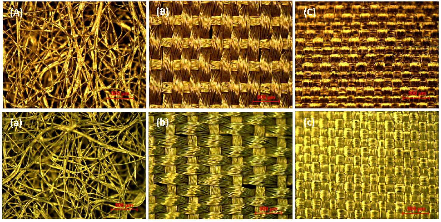
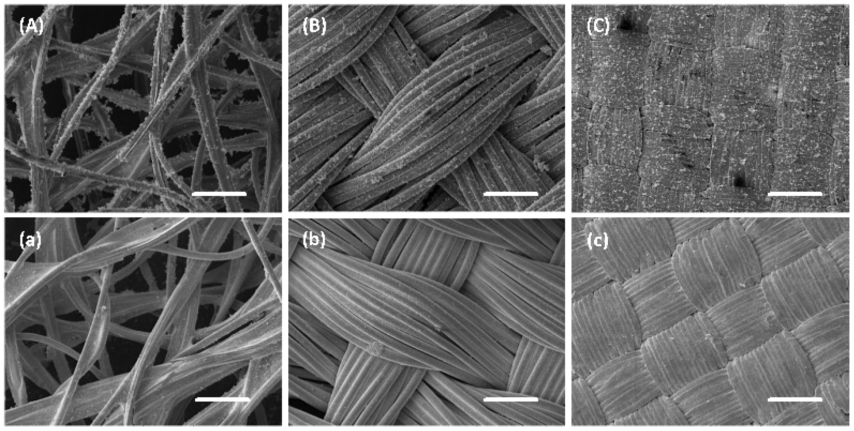
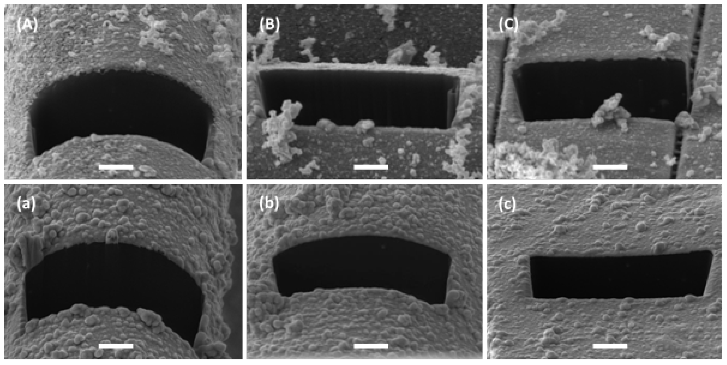
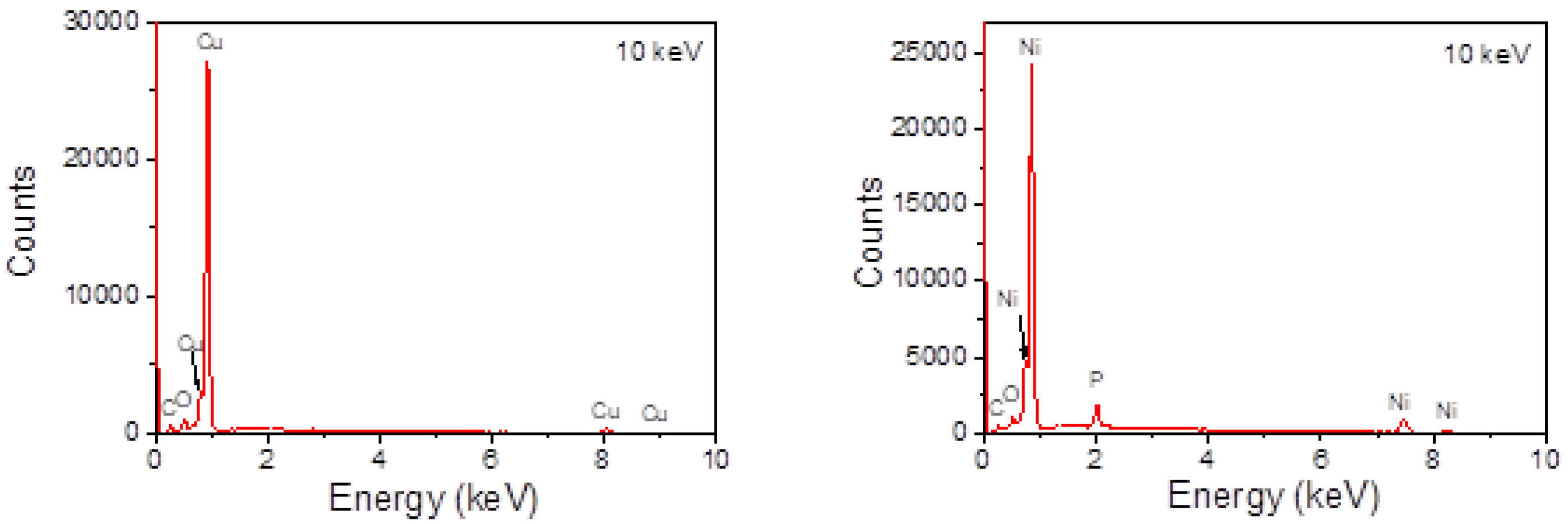
3. Results of the Metallization of Textiles

After the C u and N i electroless plating, the textiles show a metallic appearance, like copper and mickel. A homogeneous coating of C u or N i is realized on the non-conductive fibers also around the full fiber diameter. The micrograph images are shown in Figure 1.
The scanning electron microscopy (SEM) images in Figure 2 and Figure 3A–C show that there are some nanostructures on top of the homogeneous copper layer, while the nickel coated samples show a very smooth surface, almost without such nanostructures.
The energy-dispersive x-ray spectroscopy (EDX) of the copper layer shows that copper is the main element in this layer (Figure 4). The C and O peaks could be due to surface contamination or the fibers. In the nickel-coated layer, except for the main element of nickel, a small part of phosphorus is detected. The C and O peaks may be also due to surface contamination or the fibers. The phosphorus comes from the plating bath containing sodium hypophosphite monohydrate ( N a H 2 P O 2 · H 2 O ).
The average thicknesses of the metal layers deposited on the fabrics have been measured at the cross-section of the fabrics prepared by focused ion beam (FIB). The high magnification of SEM images shows a layer thickness of 175 nm (fabric produced with 55% of viscose and 45% polyester), 177 nm (100% polyestersulfone), and around 200 nm (taffeta lined and calendered polyamide textile) for the Cu-plated samples, and 375–398, 180, and 226 nm for the corresponding nickel-plated fabrics, respectively.
For experimental studies of the emissivity of reflective textiles, the standard test methods for measuring and compensating for emissions using infrared imaging radiometers (ASTM E1933) were utilized, taking into account the recommendations “Condition monitoring and diagnostics of machines-Thermography—Part 1: General procedures. Reflector method” (International standard ISO 18434-1). Selected results of the textile metallization using both Cu and Ni plating are given in Table 1. As seen, the utilization of Cu plating for the textile NL-WE-S-056 allowed us to attain an emissivity of 0.13. The lining thickness is very small ( 0.05 mm) and, therefore, the lining is neglected in the heat and humidity transport models described below. The data presented in Table 1 show the range of variations of emissivity, which is used in numerical study in Section 6.

4. Mathematical Model

The geometry of the garment is presented in Figure 5. It includes an undershirt, air layer, and thick porous fibrous batting. Thin lining reflecting the heat transported from the human body can be embedded at the boundary between the air layer and batting. The main assumption of the theoretical model is the hypothesis that the heat and moisture transport dominate in the direction which is normal to the body and garment surface, since the thickness of the garment is much less than curvature radius of the surface. The transport in the direction tangential to the body surface is neglected. This results in the one-dimensional problem formulation along the normal coordinate are designated as x.

4.1. Heat and Moisture Transport in Multi-Layer Garment

Heat transfer in a multi-layer garment is described by the partial differential equation (see, for instance, [16]):
ρ e f C P e f ( x , T ) T t = x k e f ( T ) T x + Q ( t , x , T , φ )
where T is the temperature, C P e f , ρ e f and k e f are, correspondingly, the effective heat capacity, density, and heat conduction coefficients, and φ is the relative humidity. The source term Q ( t , x , T , φ ) = ( m ˙ g s + m ˙ g l ) Δ h v a p + ( m ˙ g s + m ˙ l s ) Δ h s o r p is determined through the mass flow rate from vapor to solid m ˙ g s , the mass flow rate from liquid to solid m ˙ l s , the mass flow rate from vapor to liquid water m ˙ g l , the specific evaporation heat Δ h v a p , and the specific heat of the desorption from fibers into a gas Δ h s o r p . The moisture transport model is based on the mass conservation equation, accounting for the continuity equation:
ε g ρ v t = x D e f ( T ) ρ v x + m ˙ g s + m ˙ g l
where ρ v is the vapor density (concentration). The effective gas diffusion D e f = ε g D a / τ is expressed through the gas volume fraction ε g , the air/vapor diffusion coefficient D a and the tortuosity of fibers τ . The system of governing Equations (1) and (2) is complemented by the conservation of the bound water mass (3):
ε b w ρ w t = m ˙ g s ( t , x , T , φ ) + m ˙ l s ( t , x , T , φ )
and the liquid water (4) :
ε l ρ w t = m ˙ l s + m ˙ g l .
where ε b w is the volume fraction of the water bound in fibers, ε l is the volume fraction of the condensed water in pores, and ρ w is the water density. The effective coefficients C P e f , ρ e f and k e f are calculated from the following relations:
ρ e f = ε b w ρ w + ε g ρ g + ε d s ρ d s = ε b w ρ w + ε g ( ρ v + ρ a ) + ε d s ρ d s
ρ e f C P e f = ε b w ρ w C P w + ε g ( C P a ρ a + C P ν ρ v ) ε d s ρ d s C P d s
k e f = k g ε g k g + 1 + ε b w + ε d s k s ε g k s + 1 + ε b w + ε d s k g , k s = k w ρ w ε b w + k d s ρ d s ε d s ρ w ε b w + ρ d s ε d s
k g = k v ρ v + k a ρ a ρ v + ρ a
where ρ and k are corresponding densities and thermal conductivity coefficients, and ε d s is the volume fraction of the fiber in textile. The remaining parameters are taken from experimental approximations, published in [16,17,18,19,20,21]:
Δ h v a p = 2.792 · 10 6 160 T 3.43 T 2 , Δ h s o r p = 1.95 · 10 5 ( 1 φ ) 1 0.2 + φ + 1 1.05 φ
m ˙ g s = A s o r p ρ w ( ε b w ε b w e q ) , m ˙ l s = A s o r p ρ w ( ε b w ε b w e q ) ε l ε l , c r , ε l , c r = 0.1 ( 1 ε d s )
ε b w e q = ε d s ρ d s ρ w 0.578 R f 65 % φ 1 0.321 + φ + 1 1.262 φ , D a = 2.23 · 10 5 ( T / 273.15 ) 1.75
m ˙ g l = 4 h m ε d s d f ( ρ v ρ s a t ) , f o r   c o n d e n s a t i o n   ρ v > ρ s a t 4 h m ε d s d f ( ρ v ρ s a t ) ε l ε l , c r , f o r   e v a p o r a t i o n   ρ v ρ s a t
Here, R f 65 % is a standard value of the bound water content in fibers with respect to the mass of dry substance. This parameter referred to as also the regain is determined for the humidity of φ = 65 % . The coefficient A s o r p = 4 π D f / S f is physically responsible for the sorption rate and takes into account the form of fibers and their size distribution. It depends on the coefficient of the water diffusion in fibers D f and fiber cross section area S f = π d f 2 . The heat-exchange coefficient h t for the boundary garment environment is given. The moisture-exchange coefficient h m can be expressed through the convective heat-exchange coefficient h t using the empirical relation of Cussler (see, for instance, Formula (8) in [18]). The vapor pressure p v is determined from the perfect gas law depending on the humidity φ and the saturation pressure p v = φ p s a t ( T ) . The latter is found from the empirical relation (see Formula (9) in [18]). The density of saturated vapor ρ s a t is calculated through p s a t using the perfect gas law.
The Equations (1) and (2) require initial and boundary conditions. At the human body boundary, the heat flux q ˙ is prescribed. The boundary condition for the vapor density on the skin accounting for sweating is discussed in Section 3.3 of [18]. The Dirichlet and Neumann conditions are enforced at the boundaries between different layers (undershirt air-layer batting) for the temperature T and the vapor density ρ v . The ordinary differential Equations (3) and (4) require only the initial condition, which is defined using the equilibrium between the bound water and vapor: ε l ( x , t = 0 ) = 0 , m ˙ g s ( t = 0 ) = 0 , ε b w ( x , t = 0 ) = ε b w e q ( x , φ ( t = 0 ) ) , where the equilibrium bound water fraction ε b w e q is determined from the empirical relation (9).

4.2. Consideration of the Infrared Reflective Lining

One of the tasks of this paper is the study of the radiation heat-flux reduction using the infrared reflective lining. In this paper we use a simple model based on the decomposition of the total heat flux into the radiation flux and the heat conduction flux: Q ˙ = q ˙ r a d + q ˙ c o n d . The radiation flux q ˙ r a d is calculated using the analytical solution for the hot screens (see [22], pp. 496) between the air layer and batting, neglecting the radiation absorption in the undershirt and batting space:
q ˙ r a d = ζ σ ( T s k i n 4 T g 4 )
where σ is the Boltzmann constant, T s k i n and T g are, respectively, the temperatures of the skin and outer garment boundary, and ζ is the total radiation resistance
ζ = 1 1 ζ 1 + 1 ζ 2 + 1 ζ 3 + 1 ζ 4 2.0 + β
where ζ 1 is the emissivity of the human body (see Figure 5), ζ 2 is the emissivity of the left side of the lining, ζ 3 is the emissivity of the right side of the lining, ζ 4 is the emissivity of the left side of the batting lining, and β = 3.1 is the empiric constant chosen from the condition that the skin temperature equals to 31 C for the polyester batting of 3 cm thickness at the ambient temperature of 20 C. In the simulations presented in Section 6.1 the emissivity ζ 2 is varied, whereas other parameters are assumed to be constant ζ 1 = ζ 3 = ζ 4 = 0.9 . According to this decomposition, the Neumann boundary condition at the human body for q ˙ c o n d is reformulated as
q ˙ c o n d = Q ˙ q ˙ r a d
where Q ˙ is given. At the boundary between the garment and environment, the boundary condition reads:
q ˙ r a d k e f T x = h t
The heat-exchange coefficient h t can be taken for the turbulent flow over a plane surface with account for the radiation.

4.3. Numerical Implementation
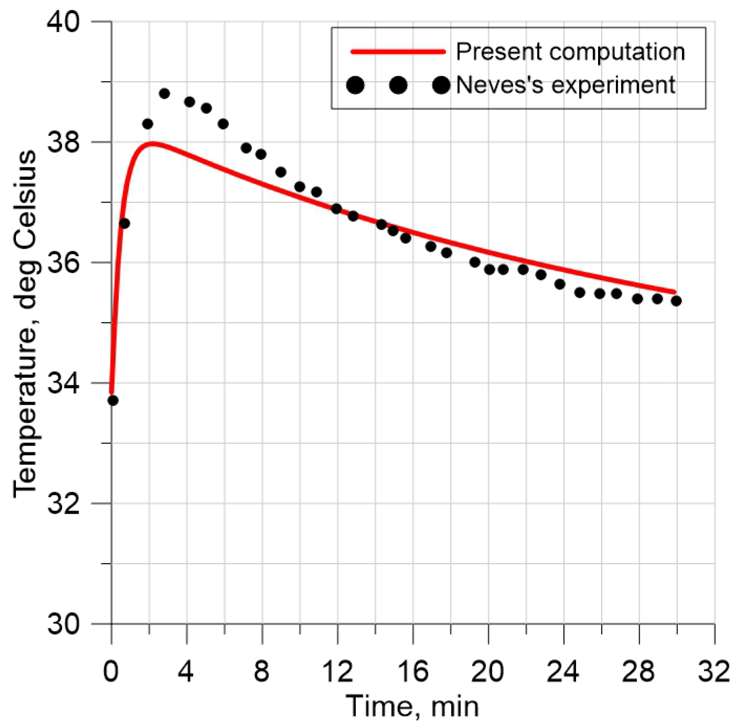
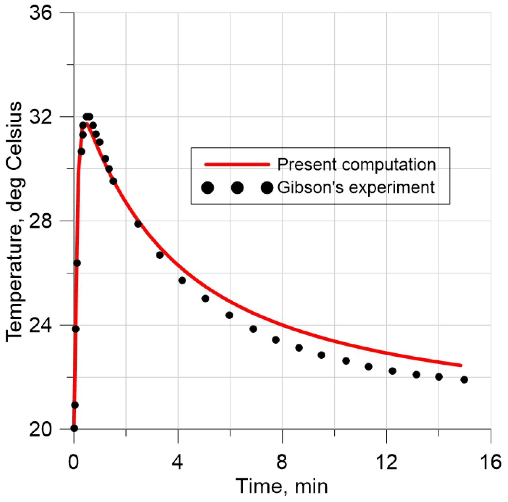
The partial differential equations involved in the mathematical model are approximated using the central difference (CDS) semi-implicit scheme. The nonlinear terms on the right-hand side of transport equations Q ( t , x , T , φ ) , m ˙ g s , m ˙ l s and m ˙ g l are treated explicitly.

5. Validation

The model and the code were thoroughly validated using numerical and experimental data available in the literature. Some selected results are presented in Figure 6 and Figure 7. The input data and calculation conditions are given in Table 2.
The experimental setup of the first validation case is shown in Figure 1 in [20]. One side of the textile sample is exposed to a saturated current of water vapor at 35 C, while the other side is exposed to a constant air flow (1 m/s) at 35 C and 40% relative humidity. The textile surface exposed to the water vapor has a plate covered by a water vapor-permeable membrane that allows only gas to pass through the plate. The temperature measured in the middle of the textile sample shows first a significant increase in time due to vapor condensation and its sorbtion by fibers. After that, the temperature tends to 35 C. For the second validation test, the measurement data were taken from [21]. The test device shown in Figure 2 in [21] uses a textile sample with both surfaces exposed to air at 20 C and 0% relative humidity. Then, the humidity rises to 100% on both sides, whereas the temperature is kept constant. Measurements for temperature performed in the middle of the textile sample show an initial increase due to condensation and sorbtion. Then, the temperature inside of the textile tends to the ambient temperature (Figure 7).
As seen, the time history for the temperature agrees well with measurements for both validation cases. Similar computations were carried out and successfully compared with [20] for cotton layers with different thicknesses and thermodynamic parameters.
Figure 6. Simulation of the temperature and comparison with measurements [20].
Applsci 13 04043 g006
Figure 7. Simulation of the temperature and comparison with measurements [21].
Applsci 13 04043 g007
Table 2. Description of validation cases.
Source[20][21]
Materialwoolwool
C p d s [J/(kg K)]13601360
ρ d s [ kg / m 3 ]13001300
k d s [W/(m K)]0.20.2
ε d s [-]0.0690.381
R e g a i n f , ( φ = 65 ) 0.150.15
[ k g H 20 k g f i b r e 1 ]
τ [-]1.182.35
h t [ W / ( m 2 K ) ]2080
h m [m/s]0.010.021
D f d f 2 [ s 1 ] 5.5 × 10 5 6.75 × 10 4
Thickness [m] 0.00857 0.001286
Initial condition
Temperature [ C]33.85 20.0
Humidity 0.35 0.0
ρ v ( 0 ) [ kg / m 3 ] 0.0125 from computations
Environment
T a m b [ C]3520
φ a m b [-] 0.4 1.0
Cell number300300
Δ t [s] 0.01 0.01
FiguresFigure 6Figure 7

6. Results of Numerical Simulations

The simulations were performed within the real time of 120 min in the garment (Figure 5) which includes an undershirt, the air layer, and batting made of a polyester or aerogel material. The material properties for the textile are given in Table 3. The width of the batting was varied in a range between 1 cm and 3 cm. The volume fraction of the fiber ε d s in the aerogel batting was changed from 0.013 to 0.313 . The heat flux from the body was set to q ˙ = 75 W / m 2 in all simulations. Simulations were performed with Δ x = 10 4 m and Δ t = 0.03 s. All simulations were performed at the ambient temperature T a m b = 20 C and humidity ϕ a m b = 0.64 . The initial conditions inside the garment were chosen for the temperature T i n = + 20 C and humidity ϕ i n = 0.4 which correspond to room parameters in the winter time. The heat-exchange coefficient at the boundary batting environment was taken as h t = 30.0 W / m 2 K .
In the calculations, the transport of humidity was taken into account, including the condensation of water in clothing.

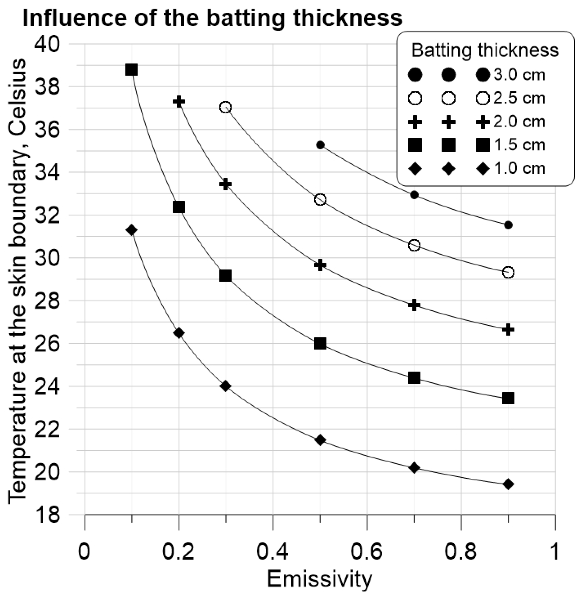
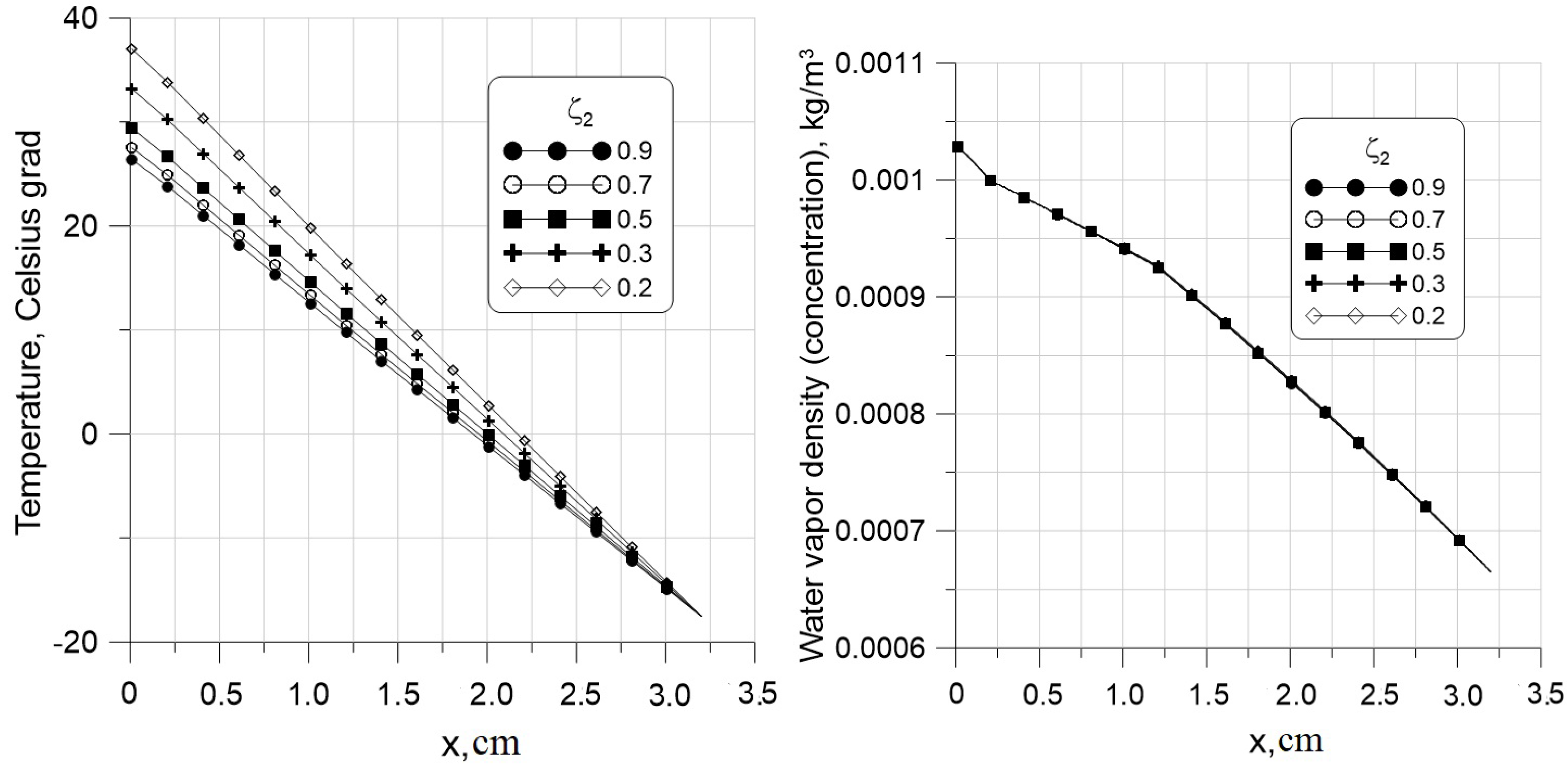
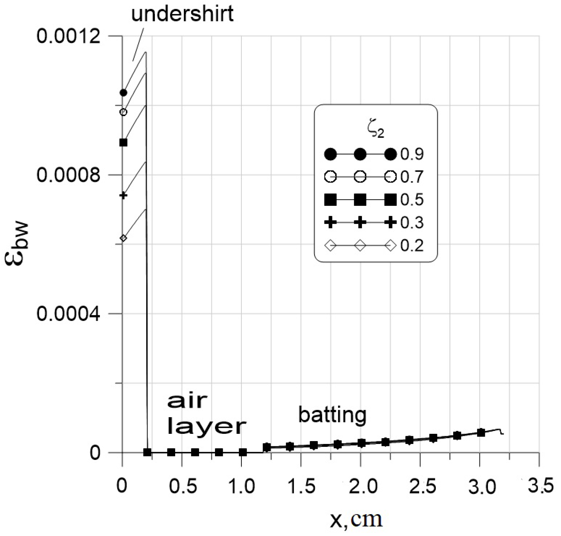
6.1. Improvement of the Protecting Garment Insulation Using the Infrared Reflective Textile

The infrared reflective lining (IR) was embedded at the boundary between the air layer and the polyester batting. It has a strong effect by reflecting back the heat transmitted from the human body (see Figure 8). The skin temperature T s k i n = 31 C can be achieved for the garment thickness of 2.5 cm for ζ 2 = 0.65 , 2.0 cm for ζ 2 = 0.4 , and 1.5 cm for ζ 2 = 0.25 . All these ζ 2 are quite achievable, as shown in the Section 3. The temperature in the domain between the body and the IR increases when the emissivity ζ 2 of the lining decreases (Figure 9, left), whereas the effect of the IR on the vapor concentration is negligible (Figure 9, right). The bound water content ε b w , depending on ζ 2 , is shown in Figure 10. Within the batting the bound water content is negligible and does not depend on the ζ 2 . On the contrary, the bound water content is substantial in the undershirt space. The smaller ζ 2 is and the higher the temperature T in the undershirt space, the lower the bound water content is in it.

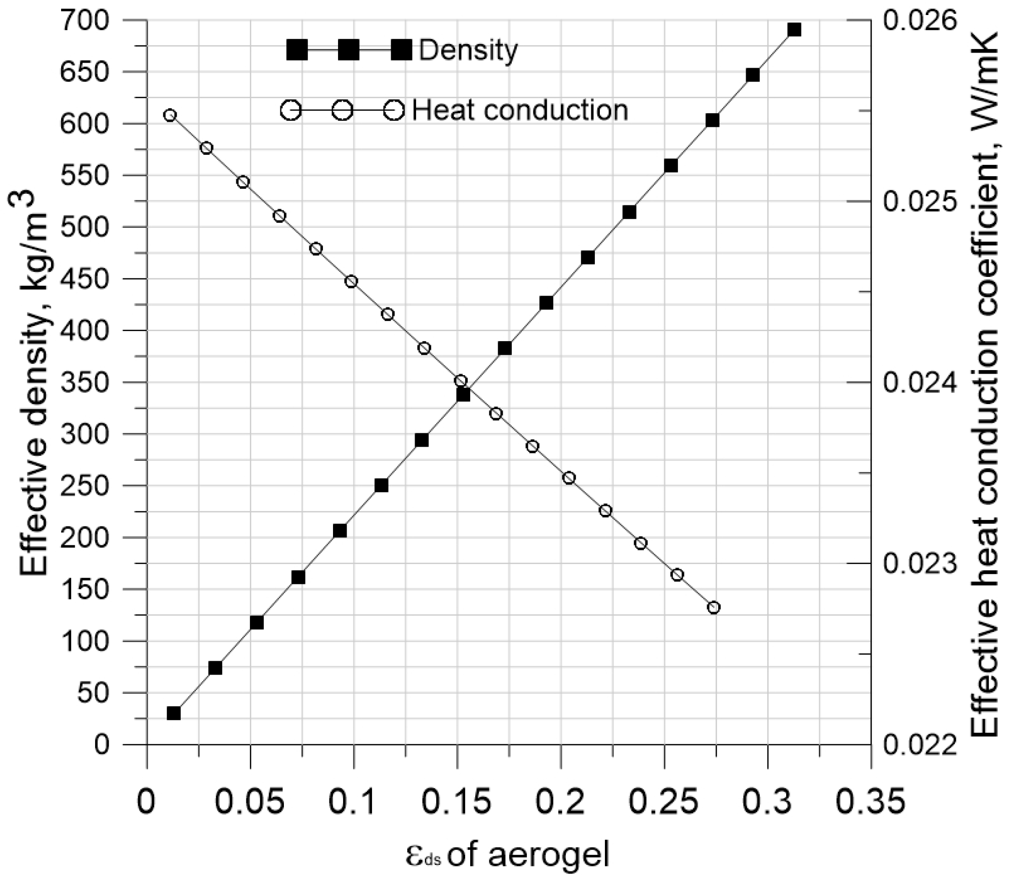
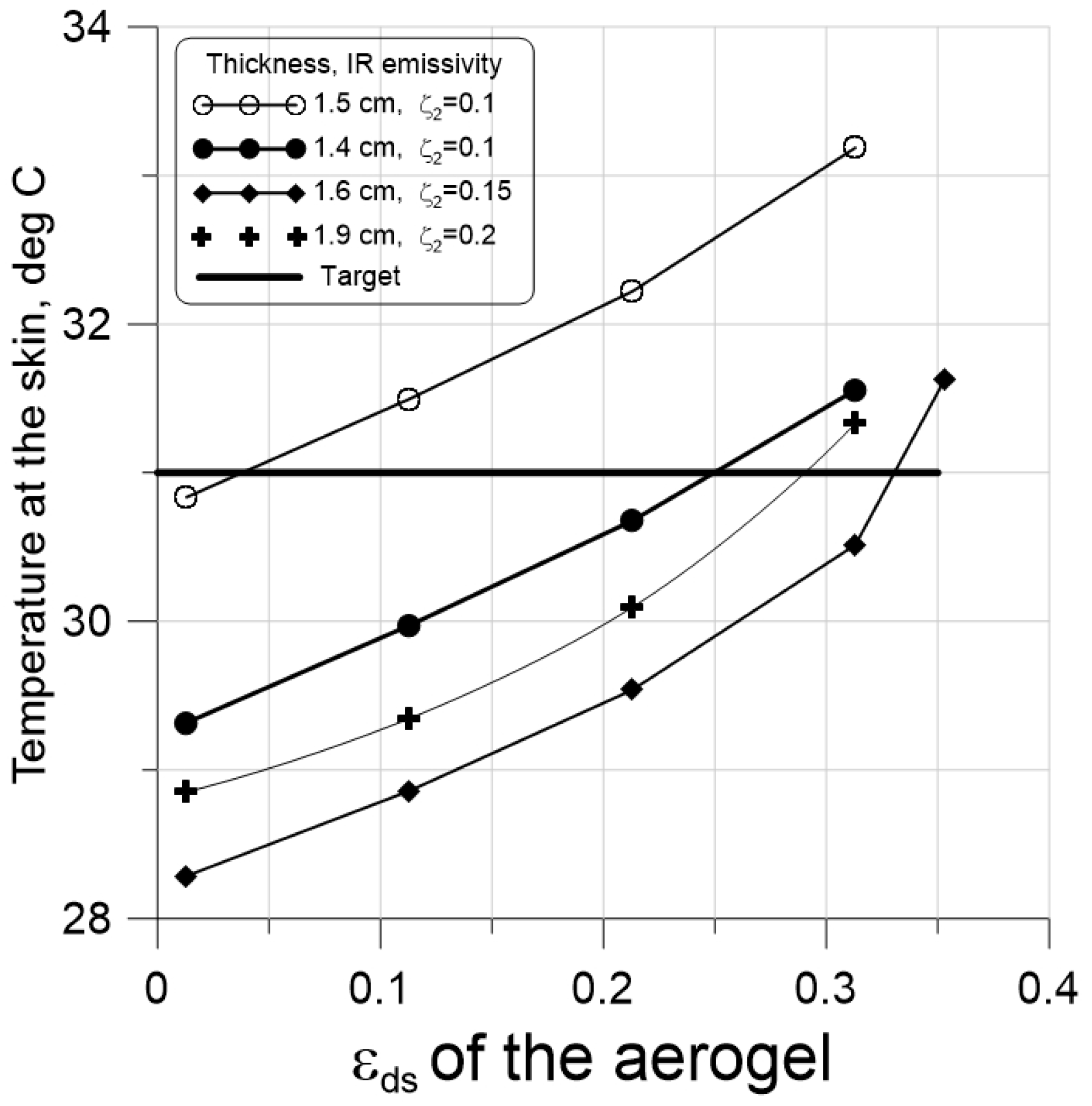
6.2. Improvement of the Protecting Garment Insulation Using the Aerogel Materials

The essence of this method of increasing the thermal insulation properties of protective clothing consists of the use of aerogel material as the main thermal insulation layer. In the study of aerogel material with a high volume fraction of fibers ε d s , initial conditions play an essential role, since the effective thermal conductivity becomes low and thermal equilibrium is achieved over long periods. In the calculations, the air in the insulating layer was gradually replaced by aerogel, which parameters are indicated in Table 3. As a result, the volume fraction of the fibers ε d s increases, which led to an increase in the effective density of the material and a decrease in the effective coefficient of thermal conductivity (Figure 11). Technically, an increase of the aerogel fraction is achieved by utilization of aerogel particles as the filling material inside of a polymer matrix consists of thick monofilament polymer fibres with a diameter of 100–200 μ m.
As follows from Figure 12, the temperature of the skin surface of 31 degrees can be achieved with a relatively low content of the aerogel ε d s = 0.013 , at which most of the insulating layer is air. The effective density of the material is only 25 kg / m 3 . To achieve T s k i n = 31 C, it is possible to reduce the thickness of the thermal insulation layer to 2.5 cm, if the volume fraction of fiber ε d s increases to 25 percent. This way cannot be considered a successful solution because the effective density of the material reaches 550 kg / m 3 , which makes the clothes significantly heavy. Humidity significantly reduces the insulating properties of protective clothing, especially with an increase in the thickness and content of fiber in the insulating layer ε d s . With a thickness of 3 cm and ε d s = 0.3 , the temperature difference between cases accounting and neglecting humidity is 1.5 degrees.
Comparing the methods of improving protective properties using aerogel with infrared reflective textiles, we note that the latter seems to be more effective, since it provides a more significant increase in temperature in the clothing space and does not lead to a significant increase in the weight of clothing.

6.3. ArTiShirt Design

The ArTishirt (Arctic t-shirt) is the concept developed by the authors of the present paper. It consists of creating thin clothing with a low weight that can protect against very cold environmental conditions. The concept is based on the use of infrared reflective textiles and aerogel materials. The simulations shown in Figure 13 give an outline of how to achieve this goal at an ambient temperature of 30 C, humidity ϕ a m b = 0.64 , and the initial conditions T i n = + 20 C and ϕ i n = 0.4 .
The skin temperature of 31 C, which we have chosen as the target, is easily achieved at ζ 2 = 0.1 already with a small fraction of aerogel 0.04 with an insulation material thickness of 1.5 cm. The reduction of the thickness by 1 mm requires an increase of the aerogel fraction to 0.25 . The increase of ζ 2 to 0.2 results in the growth of the aerogel fraction ε d s to ≈0.33 for a relatively small thickness of the insulating layer, 1.6 cm. These numerical results show that the design of cold-protection clothing with a thickness of about 1.5 cm is technically visible. These results will be confirmed during the measurements.

7. Conclusions

The paper presents a mathematical model describing the coupled transport of temperature, humidity, and bound and condensed water within a cold-protecting garment. A one-dimensional formulation of the mathematical problem is utilized, assuming that the transport in a normal direction to the human body dominates. The thermal radiation transport is explicitly considered by the subdivision of the heat flux into radiative and conduction parts to take into account the effect of infrared reflective textiles.
The study was carried out for a sandwich garment construction, including a very thin undershirt, an air layer, and batting. Two techniques of improvement of the heat-insulating properties of protective garments were examined: the use of aerogel material and infrared reflective linings (thin infrared reflective textile layers). In the first technique, an aerogel material is used which possesses a thermal conductivity much lower than the air one. By displacing the air within the batting by the aerogel material, one can substantially reduce the thermal conductivity of the whole garment. In the second technique, a thin infrared reflective layer is inserted at the inner boundary of the batting, and reflects the heat radiated by the human body back. The technological aspects of manufacturing such reflective textiles are discussed.
The numerical investigations show that:
  • The use of aerogel has been proven to be a possible way to improve the protective properties of clothing. However, it has the serious disadvantage of increasing the weight of the garment by displacing light air with the heavier aerogel material.
  • The use of the infrared reflective textile is the most effective of the two methods studied. Due to the reflection of the radiant heat flow coming from the human body, the skin temperature rises and the thermal insulation of clothing is significantly improved. It allows a substantial reduction of the thickness and weight of the garment, keeping the human skin temperature constant.

Author Contributions

Conceptualization, J.P. and K.R.; methodology, I.C.; software, N.K.; formal analysis, N.K. and K.R.; investigation, I.C. and G.J.; writing—original draft preparation, I.C., G.J., N.K. and J.P.; project administration, K.R. All authors have read and agreed to the published version of the manuscript.

Funding

This research was funded by the Federal Ministry for Economic Affairs and Climate Action (BMWK) within the IraSME program, grant number KK5037208CD1.

Institutional Review Board Statement

Not applicable.

Informed Consent Statement

Not applicable.

Data Availability Statement

The data presented in this study are available on request from the corresponding author.

Acknowledgments

The authors thank Barbara Geisenhainer (Leibniz IPHT) for supporting the wet chemical metal deposition, Andrea Dellith (Leibniz IPHT) und Jan Dellith (Leibniz IPHT) for SEM and EDX measurements.

Conflicts of Interest

The authors declare no conflict of interest.

Nomenclature

C p specific heat capacity [J/(K kg)]
Ddiffusion coefficient [m2/s]
M H 2 O H 2 O molar mass [kg/mol]
Runiversal gas constant
Ttemperature [K]
h m moisture exchange coefficient [W/(m2 Pa)]
h t heat exchange coefficient [W/(m2 K)]
kthermal conductivity [Wm/K]
mmass [kg]
m ˙ desorption rate [kg/(m3s)]
ppressure [N/m 2 ]
ttime [s]
xnormal coordinate [m]
Greek symbols
Δ h v a p specific evaporation heat [m2/s2]
Δ h s o r p specific desorption heat [m2/s2]
Δ t time step [s]
εvolume fraction [-]
ρdensity [kgm 3 ]
τtortuosity [-]
φrelative humidity [-]
ζemissivity coefficient [-]
Subscripts
aair
ambambient
bwbounded water
dsdry solid
efeffective
eqequilibrium
ffiber
ggas
ininitial
satsaturation
sorpsorption
vvapour

References

  1. Dolez, P.I.; Marsha, S.; McQueen, R.H. Fibers and Textiles for Personal Protective Equipment: Review of Recent Progress and Perspectives on Future Developments. Textiles 2022, 2, 349–381. [Google Scholar] [CrossRef]
  2. Schacher, L.; Adolphe, D.C.; Drean, J. Comparison between thermal insulation and thermal properties of classical and microfibres polyester fabrics, Int. J. Cloth. Sci. Technol. 2000, 12, 84–95. [Google Scholar] [CrossRef]
  3. Gao, J.; Yu, W.; Pan, N. Structures and Properties of the Goose Down as a Material for Thermal Insulation. Tex. Res. J. 2007, 77, 617–626. [Google Scholar]
  4. Cherunova, I.; Stenkina, M.; Kornev, N. Verification of thermal models in the design of personal protective equipment against cold. IOP Conf. Ser. Mater. Sci. Eng. 2021, 1029, 012035. [Google Scholar] [CrossRef]
  5. Yan, Q.; Xin, B.; Liu, Y. Development and Application of Infrared Radiation Materials in the Field of Textile and Clothing. J. Phys. Conf. Ser. 2021, 1790, 012054. [Google Scholar] [CrossRef]
  6. Cherunova, I.; Dhone, M.; Kornev, N. Coupled thermo-aerodynamical problems in design of protection cloth. In COUPLED VI: Proceedings of the VI International Conference on Computational Methods for Coupled Problems in Science and Engineering, Venice, Italy, 18–20 May 2015; Schrefler, B., Oñate, E., Papadrakakis, M., Eds.; International Center for Numerical Methods in Engineering (CIMNE): Barcelona, Spain, 2015; pp. 1303–1311. [Google Scholar]
  7. Militky, J.; Kremenakova, D.; Venkataraman, M.; Vecernik, J.; Martinkova, L.; Marek, J. Sandwich Structures Reflecting Thermal Radiation Produced by the Human Body. Polymers 2021, 13, 3309. [Google Scholar] [CrossRef]
  8. Breckenridge, J.R. Insulating Effectiveness of Metallized Reflective Layers in Cold Weather Clothing Systems; Technical Report; US Army Medical Research and Development Command: Natick, MA, USA, 1978; Available online: https://www.readcube.com/articles/10.21236%2Fada070463 (accessed on 21 March 2023).
  9. Arrieta, G.; Echaniz, T.; Olmos, J.M.; Fuente, R.; Urcelay-Olabarria, I.; Igartua, J.M.; Tello, M.J.; Lopeza, G.A. Evolution of the infrared emissivity of Ni during thermal oxidation until oxide layer opacity. Infrared Phys. Technol. 2019, 97, 270–276. [Google Scholar] [CrossRef]
  10. Khalili, A.; Mottaghitalab, A.; Hasanzadeh, M.; Mottaghitalab, V. Rejection of far infrared radiation from the human body using Cu-Ni-P-Ni nanocomposite electroless plated PET fabric. Int. J. Ind. Chem. 2017, 8, 109–120. [Google Scholar] [CrossRef] [Green Version]
  11. Jia, G.; Plentz, J.; Dellith, A.; Schmidt, C.; Dellith, J.; Schmidl, G.; Andrä, G. Biomimic vein-like transparent conducting electrodes with low sheet resistance and metal consumption. Nano-Micro Lett. 2020, 12, 19. [Google Scholar] [CrossRef] [Green Version]
  12. Schmidl, G.; Jia, G.; Gawlik, A.; Andrä, G.; Richter, K.; Plentz, J. Aluminum-doped zinc oxide-coated 3D spacer fabrics with electroless plated copper contacts for textile thermoelectric generators. Mater. Today Energy 2021, 21, 100811. [Google Scholar] [CrossRef]
  13. Schmidl, G.; Gawlik, A.; Jia, G.; Andrä, G.; Richter, K.; Plentz, J. 3d spacer fabrics for thermoelectric textile cooling and energy generation based on aluminum doped zinc oxide. Smart Mater. Struct. 2020, 29, 125003. [Google Scholar] [CrossRef]
  14. Schmidl, G.; Jia, G.; Gawlik, A.; Lorentz, P.; Ziegler, G.; Dellith, M.; Diegel, M.; Plentz, J. Copper iodide on spacer fabrics as textile thermoelectric device for energy generation. Materials 2023, 16, 13. [Google Scholar] [CrossRef]
  15. Geng, Y.; Lu, C.; Liang, M.; Zhang, W. Characterization and Properties of Electroless Nickel Plated Poly (ethylene terephthalate) Nonwoven Fabric Enhanced by Dielectric Barrier Discharge Plasma Pretreatment. Plasma Sci. Technol. 2010, 12, 6. [Google Scholar] [CrossRef]
  16. Gibson, P. Modeling Heat and Mass Transfer from Fabric-Covered Cylinders. J. Eng. Fibers Fabr. 2009, 4, 1–8. [Google Scholar] [CrossRef] [Green Version]
  17. Chitrphiromsri, P.; Kuznetsov, A.V.; Song, G.; Barker, R.L. Investigation of Feasibility of Developing Intelligent Firefighter-Protective Garments Based on the Utilization of a Water-Injection System. Numer. Heat Transf. Part Appl. Int. J. Comput. Methodol. 2006, 49, 27–450. [Google Scholar] [CrossRef]
  18. Chorny, A.; Cherunova, I.; Kornev, N. Thermophysical interaction in the shoe-foot system during sport activity. Int. J. Heat Mass Transf. 2021, 176, 121386. [Google Scholar] [CrossRef]
  19. Gibson, P. Multiphase flow through porous media. In Thermal and Moisture Transport in Fibrous Materials; Pan, N., Gibson, P., Eds.; CRC Press: Cambridge, UK, 2008; pp. 308–357. [Google Scholar]
  20. Neves, S.; Campos, J.; Mayor, T.S. On the determination of parameters required for numerical studies of heat and mass transfer through textiles. Methodologies and experimental procedures. Int. J. Heat Mass Transf. 2015, 81, 272–282. [Google Scholar] [CrossRef] [Green Version]
  21. Gibson, P.; Charmchi, M. The Use of Volume-Averaging Techniques to Predict Temperature Transients Due to Water Vapor Sorption in Hygroscopic Porous Polymer Materials. J. Appl. Polym. Sci. 1997, 64, 493–505. [Google Scholar] [CrossRef]
  22. Arpaci, V.S.; Kao, S.H.; Selamet, A. Introduction to Heat Transfer; Prentice-Hall: Hoboken, NJ, USA, 1999; pp. 308–357. [Google Scholar]
Figure 1. Micrograph images of copper-plated textiles NL-VL-S-016 (A), NL-WE-S-056 (B) and NL-WE-S-045 (C) and the corresponding textiles with N i plating in (ac).
Applsci 13 04043 g001
Figure 2. SEM images of copper-plated textiles consisting of 55% of viscose and 45% polyester (A), 100% polyestersulfone (B), a taffeta lined and calendered polyamide textile (C) and the corresponding fabrics (A-a, B-b and C-c) with Ni plating in (ac). Scale bar for all the images: 100 μ m.
Applsci 13 04043 g002
Figure 3. High magnification SEM images at the cross-section prepared by focused ion beam (FIB) for the determination of the coated layer thickness. Fabrics produced by 55% of viscose and 45% polyester (A), by 100% polyestersulfone (B), a taffeta lined and calendered polyamide textile (C) coated with copper, respectively. The corresponding fabrics coated with nickel are presented in (ac), respectively. Scale bar for all samples: 2 μ m.
Applsci 13 04043 g003
Figure 4. EDX measurements on the C u (left) and N i (right) layer deposited on textiles. Measurements are carried out at an electron beam energy of 10 keV.
Applsci 13 04043 g004
Figure 5. Sketch of the garment geometry. ζ i are emissivities. Circles are nodes of the computational grid.
Applsci 13 04043 g005
Figure 8. Influence of the IR on the temperature at the boundary between the skin and the undershirt after 120 min. Emissivity of the IR ζ 2 varies between 0.1 and 0.9 .
Applsci 13 04043 g008
Figure 9. Influence of the IR on the temperature (left) and the vapor concentration (right) distribution across the garment after 120 min. Polyester batting thickness is 2.0 cm.
Applsci 13 04043 g009
Figure 10. Influence of the IR on the bound water content in fibers.
Applsci 13 04043 g010
Figure 11. Influence of the volume fraction of aerogel ε d s on the effective density and coefficient of thermal conductivity in the center of the insulating layer (batting) of clothing.
Applsci 13 04043 g011
Figure 12. Influence of the volume fraction of aerogel ε d s on the temperature on the human skin at different thicknesses of the insulating layer, taking into account (solid lines) and without taking into account (dotted lines) the transport of humidity inside clothing.
Applsci 13 04043 g012
Figure 13. Influence of the volume fraction of aerogel ε d s on the skin temperature at different ζ 2 and insulation layer thickness.
Applsci 13 04043 g013
Table 1. Selected results of textile metallization.
ArticlePlatingDescriptionMaterialEmissivity
NL-VL-S-016Cuthin55% Viskose 0.50
NL-VL-S-016Nifleece+45% Polyester 0.68
NL-WE-S-045CuTaffeta lining,Polyamid 0.48
NL-WE-S-045Nicalendered, windproof 0.29
NL-WE-S-056Cublack fine fabric100% Polyester 0.13
Table 3. Properties of materials used in simulations.
MaterialThickness C pds ρ ds k ds ε ds R f τ
cmJ/ K kgkg/m 3 W/m K[-][-][-]
undershirt0.217201300 0.2 0.06 0.15 2.35
batting1–313401142 0.14 0.02 0.004 1.5
polyester
batting1–37002200 0.017 0.013 0.004 1.6
aerogel 0.313
Disclaimer/Publisher’s Note: The statements, opinions and data contained in all publications are solely those of the individual author(s) and contributor(s) and not of MDPI and/or the editor(s). MDPI and/or the editor(s) disclaim responsibility for any injury to people or property resulting from any ideas, methods, instructions or products referred to in the content.

