
Mechanical Characteristics of an Open-Buried Double-Arch Tunnel during Construction
Abstract
:1. Introduction
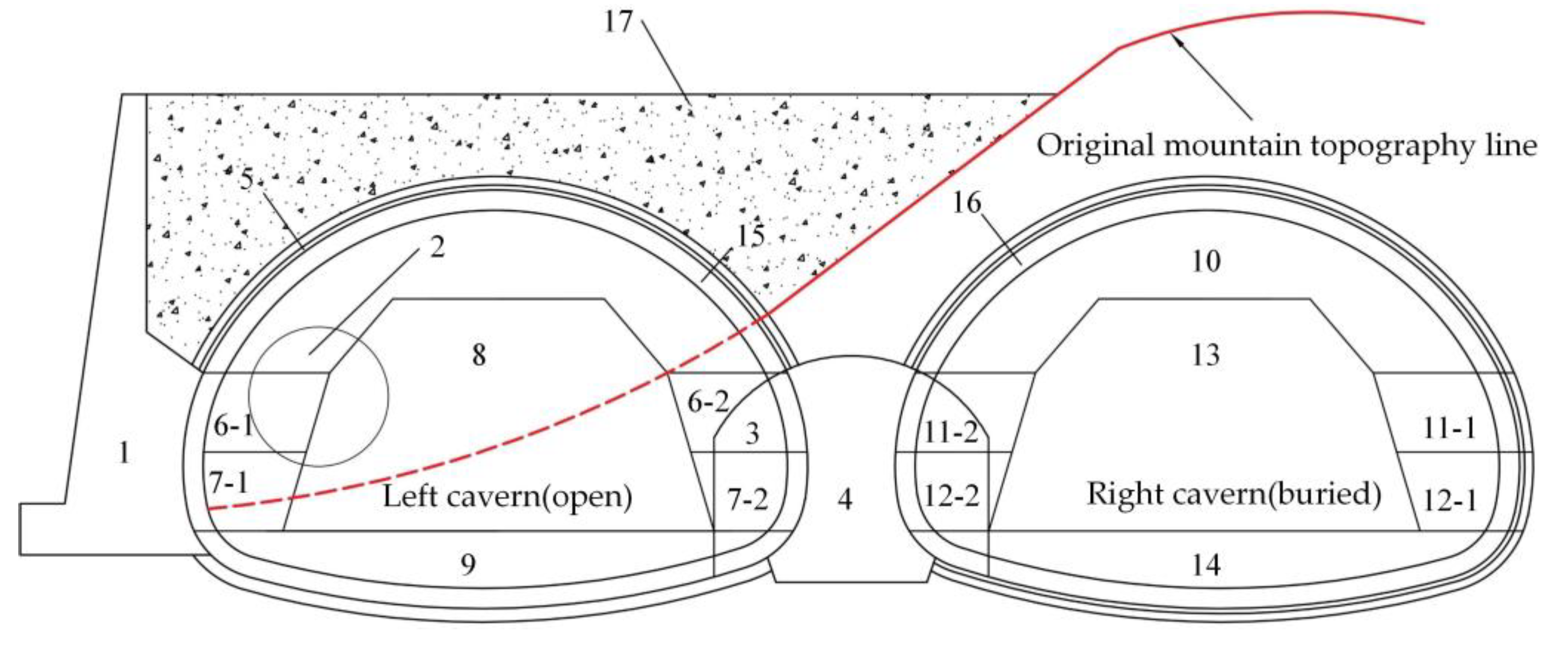
2. Project Summary
2.1. Tunnel on Xiajuan Road
2.2. Engineering Geological Condition
2.3. Construction Process of the Tunnel Entrance
3. On-Site Monitoring Program
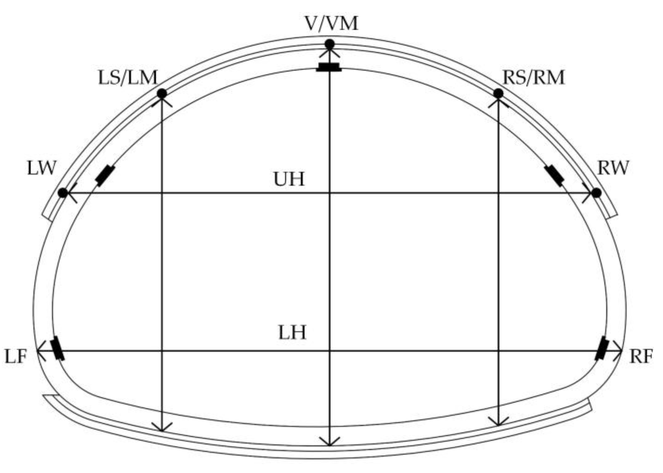
3.1. Monitoring Objects and Content
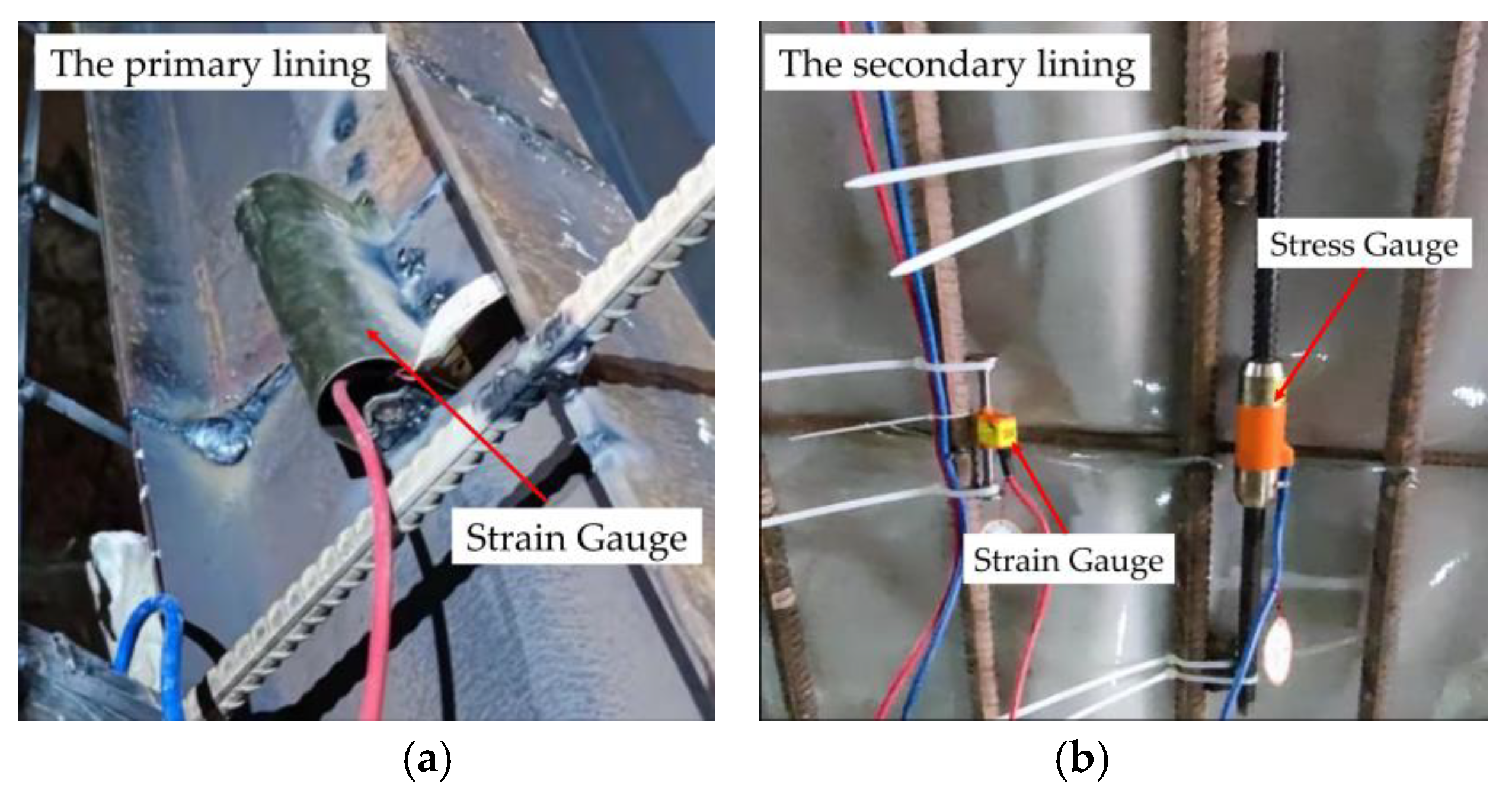
3.2. Component Arrangements
3.3. Construction Cases
4. On-Site Test Results and Analysis
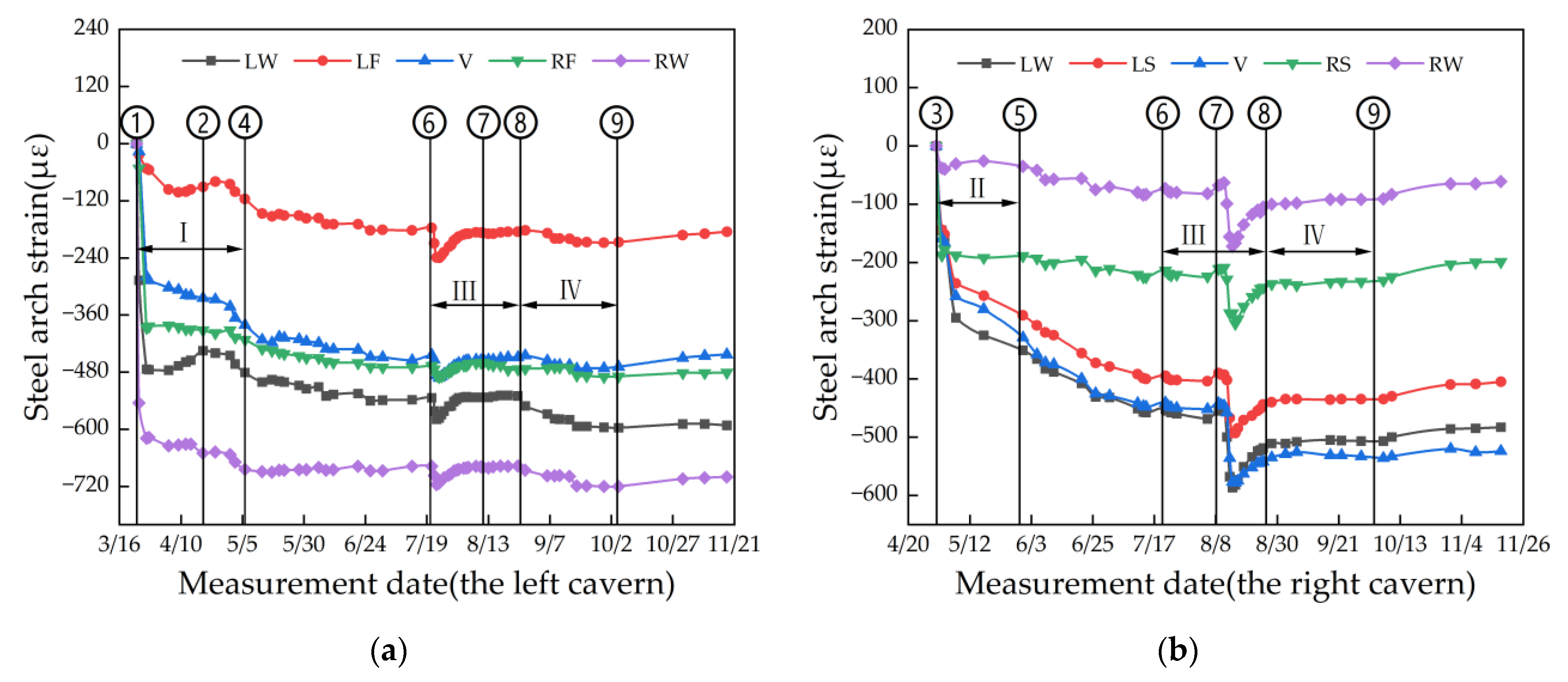
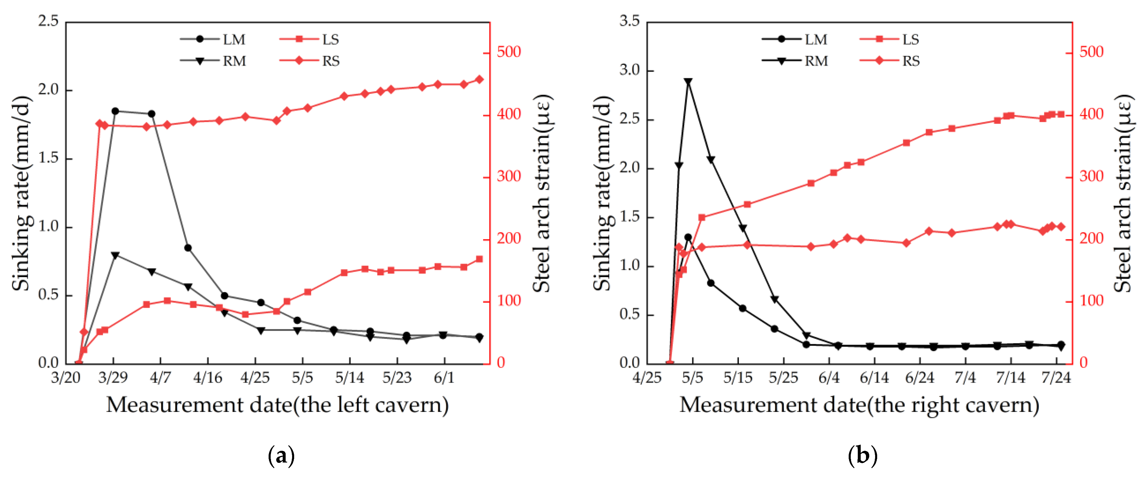
4.1. Steel Arch Strain
- (1)
- Construction stage I. The up-step of the left tunnel is located above the original hillside surface. Consequently, after the construction of the deflecting retaining wall, the primary lining at the up-step of the left tunnel is constructed (as shown in Figure 2). It is seen that after the completion of the primary lining, the strain at the steel arch shows a rapid growth trend at the early stage due to the effect of the concrete, formwork, and its own gravity. The strain development at each potion of the steel arch gradually flattens out with time. It is worth noting that the strain at the remaining measurement point continues to increase while the strain at the LW and the LS of the steel arch decreases because the right side of the steel arch that overlaps with the mid-partition wall shares part of the right side of the surrounding rock pressure. However, when the mid-step of the left cavern is excavated, the strain at the LW and the LS increases simultaneously, and the increasing trend is smaller than at other positions. This indicates that the soil displacement of the middle-lower parts of both sides of the left cavern are caused by the excavation of the mid-step, driving a stress adjustment of the surrounding rock and squeezing the steel arch to a certain extent. Under the deflecting effect of right hillside body, the mid-partition wall on the right side shows a tendency to deflect to the left cavern after the removal of surrounding rock at the left side. Consequently, the pulling and squeezing effect at the steel arch on the same side is more obvious. During the construction of the lower step of the cavern, the above phenomenon becomes more obvious, and the strain growth increases significantly. It is seen that after the construction of the open cavern by the concealed method, the primary lining plays a certain role in the supporting action, especially for the hillside body on the mid-partition wall. In summary, regarding the construction of the open-buried double-arch tunnel, although the influence of the traditional (buried tunnel) up-step excavation on the tunnel supporting system and surrounding rock can be ignored, the soil excavation of the middle-lower part of the open cavern, which is equivalent to the unloading of the slope angle, has induced a stress adjustment of the rock around the left cavern and an attitude change of the mid-partition wall. It is necessary to adopt engineering measures (e.g., installing the deflecting retaining wall) to improve the stability of the whole tunnel and slope subjected to the open cavern construction load.
- (2)
- Construction stage II. After the excavation and erection of the primary lining at the up-step of the right cavern, the surrounding rock pressure is released within 3 days. The steel arch strain increases rapidly when it begins to bear the surrounding rock pressure. As the up-step of the right cavern continues to be excavated, the strain of the steel arch at the RW and the RS is essentially stable, while the other points continue to increase until the construction of the invert begins. The reason for the above phenomenon is that the right side of the right cavern is on a higher elevation of mountain topography, while the left side is reduced in height and linked with the mid-partition wall. The caverns are in a right-to-left skewed topography. After the excavation of the up-step and the invert in the right cavern, the surrounding rock deforms towards the left side with a stress adjustment, and the left side of the steel arch bears the surrounding rock pressure. It is seen that the location of the joint area (near the mid-partition wall) is a sensitive area during the buried-cavern construction of the open-buried double-arch tunnel.
- (3)
- Construction stage III. The strain at the steel arch increases rapidly in both caverns within 3 days after the secondary lining is applied, and reaches the maximum value during the monitoring period. After 5 days, the strain at the steel arch of the left and right caverns decreases rapidly until they are essentially stable. The reason for the above phenomenon is that contact pressure arises between the primary and the secondary linings due to gravity and the solidification of the concrete when the secondary lining is completed [33]. While the secondary-lining trolley is still acting on the secondary lining, the contact pressure between the linings causes the strain at the steel arch to increase rapidly. When the secondary-lining trolley is removed, there is a certain release of interaction force between the linings. Meanwhile, the secondary lining concrete at this time tends to be stable due to its solidification. It is worth noting that the strain of the steel arch at each measurement point of the right cavern did not increase repeatedly due to the soil excavation when the secondary lining of the left cavern was completed. The strain tends to be stable after it slightly decreases during the construction of the secondary lining of the right cavern. It is seen that the supporting strength at the open cavern side in the open-buried double-arch tunnel is effectively utilized, which is of great significance to guarantee the stability of the tunnel structure system.
- (4)
- Construction stage IV. When the secondary linings of the left and right caverns reach the design strength, the soil is back-filled on the left cavern (open cavern). It is seen that the backfill presents different effects on the strain at the steel arch in both caverns. Soil backfill increases the strain at the steel arch of the left cavern again, which is especially significant at the LW, while the strain at the steel arch of the right cavern decreases at the end of backfill. Soil backfill will increase the surrounding rock pressure around the left cavern, which indicates that it causes a transformation from an “open” cavern into a “buried” cavern. The bias pressure caused by the slope is balanced, which subsequently reduces the strain at the steel arch of the right cavern, and increases the strain at the left cavern. During the whole process, the strain at each measurement point is still within the safe range.
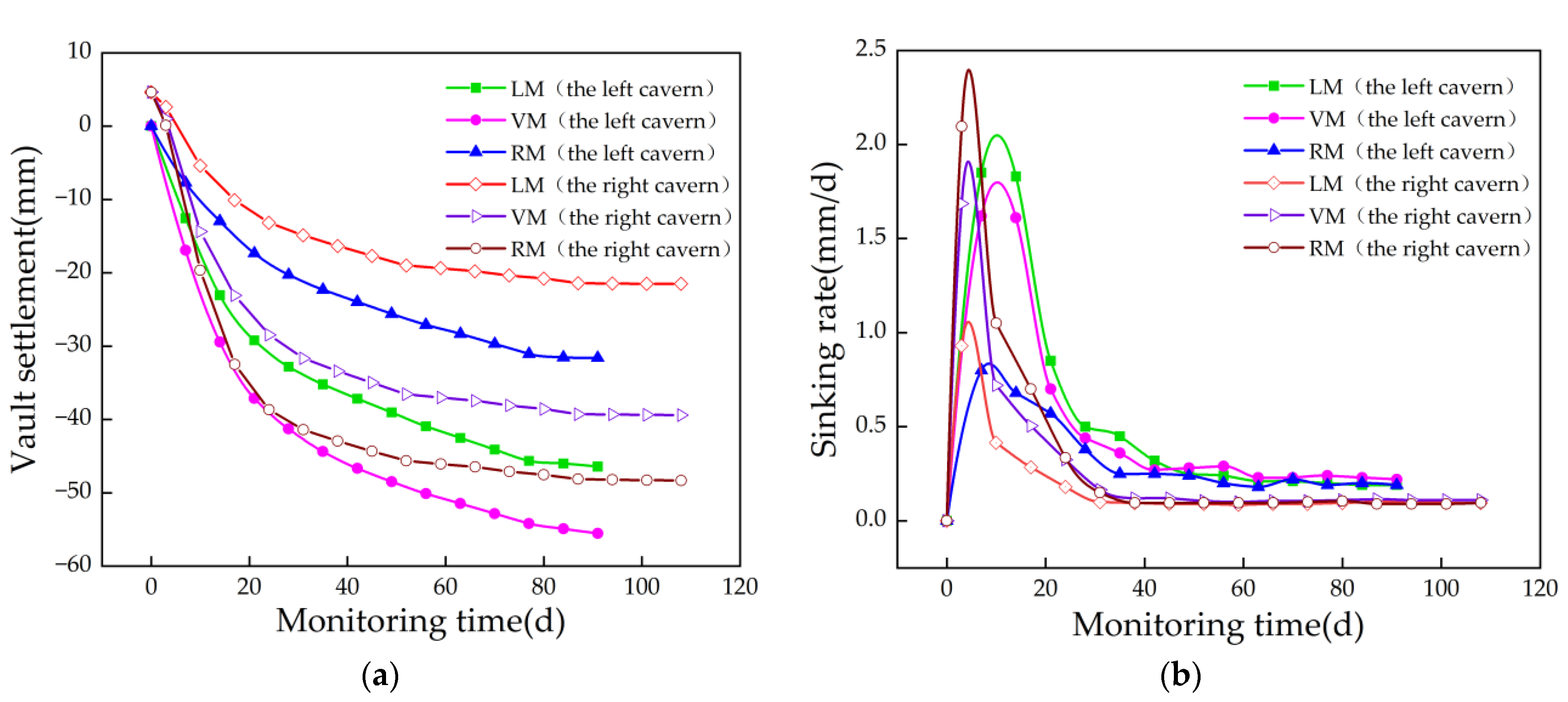
4.2. Vault Settlement
- (1)
- The process of vault settlement can be divided into three stages: the rapid development stage within 15 d after the construction of up-step, the continuous development stage before the application of the invert, and the gradual stabilization stage after the application of the invert. The vault settlement at each stage accounts for about 50%, 30%, and 20% of the total settlement. After the application of the invert, the sinking rate gradually tends to be stable.
- (2)
- The stabilization periods of vault settlement in the left and right caverns are different. It takes 42 d and 30 d for vault settlement of the left and right caverns to reach stability, respectively. At the section of 30.5 m to working face, the settlement value of the vault at the left cavern reaches about 80% of the total settlement. This result is consistent with the observation of Yuan et al. [34]. Since this study relies on an open-buried double-arch tunnel, there is no surrounding rock above the open cavern. This prompts the time for the vault settlement to reach stability, and reduces the distance from the working face between the former cavern and the later cavern.
- (3)
- The maximum vault settlement position and the sinking rate in each cavern are different. The maximum vault settlement and sinking rate of the left cavern occur at the VM, while they occur at the RM in the right cavern. The minimum settlement and sinking rates of each cavern occur in the measurement point near the mid-partition wall. The reason is that the deflecting retaining wall and the mid-partition wall effectively suppress the overall sinking of the primary lining at the measurement points. The maximum vault settlement of the left and right caverns is 55.5 mm and 49.0 mm, respectively, which are about 1/3 of the admissible value (150 mm). The open-excavation and concealed construction method is effective to control the settlement of the tunnel during the construction of the tunnel.
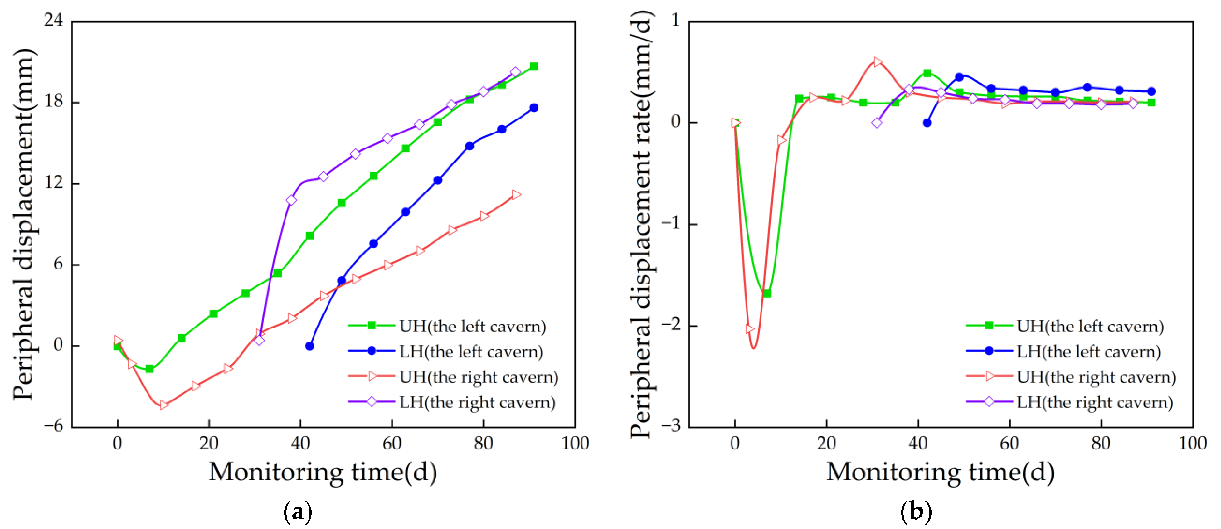
4.3. Peripheral Displacement
- (1)
- The peripheral displacement around the tunnel shows an inward convergence, and then experiences an outward extension. After the construction of the up-step of the tunnel, the peripheral displacement of the left and right caverns tends to move inwards. The main reason for this phenomenon is that the mid-partition wall moves towards the shallowly buried side (left cavern) subjected to the deflection of slope. Regarding the right cavern, after the construction of the up-step of the right cavern, the mid-partition wall moves to the right because of the construction deflection pressure caused by tunneling construction between the caverns. A similar phenomenon is also discussed by Duan et al. [35] with regard to a bias-pressure double-arch tunnel, where the bias effect caused by the asymmetric construction is not considered. When the plastic zone of the surrounding rock is initially formed, the primary lining begins to work, and the relative displacement of the cavern gradually moves toward both sides.
- (2)
- The displacement development pattern of the tunnel cavern is different when subjected to different construction stages. For the first half of the month, because of a rapid stress release of the surrounding rock, the maximum peripheral displacement rate occurs at the early stage, and it moves toward the inner side. Compared with the construction of the lower step, the mid-step construction shows a greater effect on the accumulated displacement and the displacement rate at the UH. The effect of the invert construction on the accumulated periphery displacement and the displacement rate at the UH is greater than the construction of the mid-step. The periphery displacement rate of the left and right caverns converges gradually after the invert construction, which indicates that the timely construction of the invert plays an important role in controlling the displacement of the primary lining and surrounding rock.
- (3)
- The accumulated peripheral displacement around the UH is larger than the LH because the deflecting retaining wall and the mid-partition wall restrict the horizontal displacement of the lower ling structure and surrounding rock. The accumulated peripheral displacement around the UH is smaller than the LH since there is no deflecting retaining wall on the right side of the right cave, which means that no restraint exists outside the right cave.
4.4. Correlation Analysis
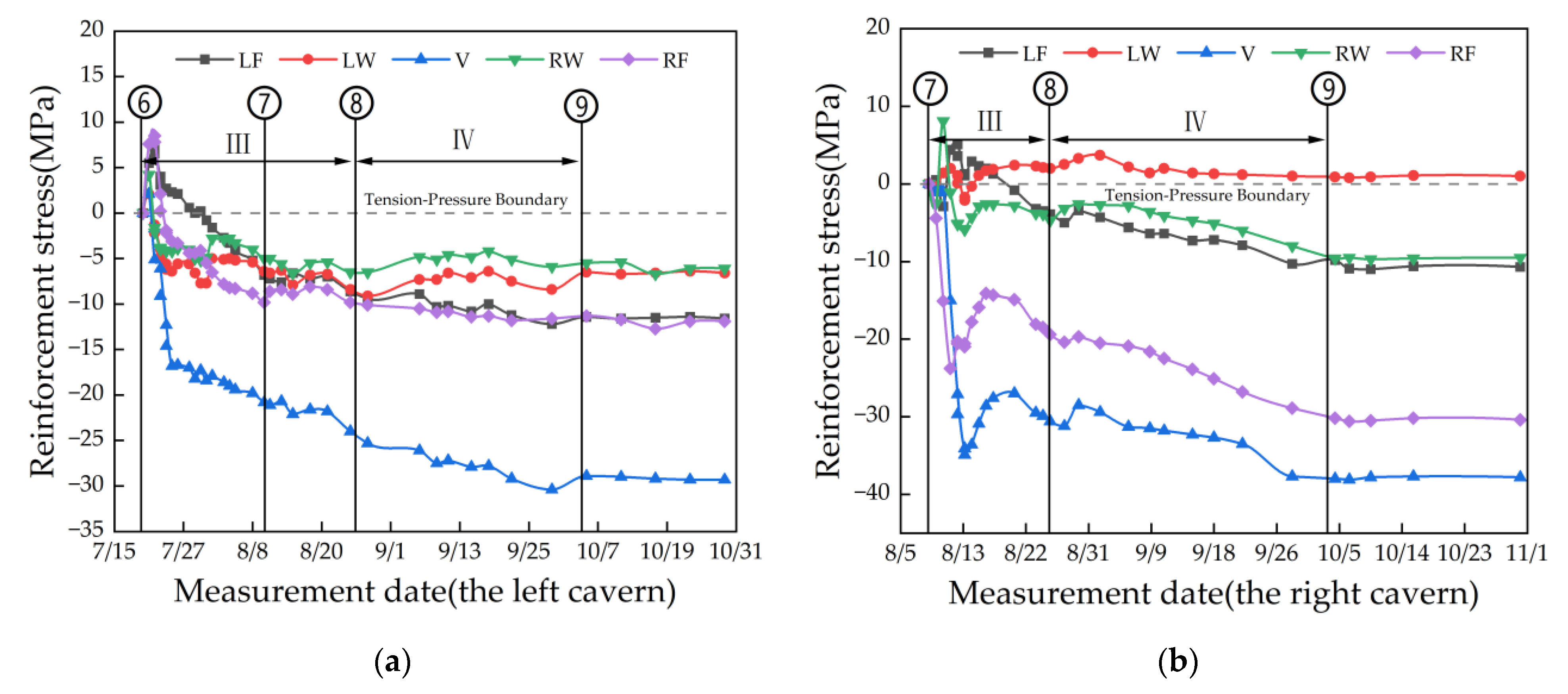
4.5. Reinforcement Stress of the Secondary Lining
- (1)
- The mechanical properties of the reinforcement in the secondary lining are measured throughout the process of concrete casting and maintenance. After the secondary lining concrete is cast in the left and right caverns of the tunnel, the secondary lining forms a temperature gradient from the inside to the outside due to a large amount of heat released from the hydration heat reaction of the concrete. When the concrete cools down and shrinks from a high temperature, this results in tensile stress (temperature stress) [36], causing a significant increase in the tensile stress in the secondary lining. When the maintenance of the secondary lining concrete is completed, it presents a dominated compressive stress.
- (2)
- Compared with the left cavern, the distribution of stress in the right cavern is more discrete, and a great difference is observed among different measurement points. The left shoulder of the right cavern is dominated by tensile stress. The supporting effect of the mid-partition wall leads to a relatively concentrated reinforcement stress at the location of the arch waist near the side of the mid-partition wall in the left and right caverns. If the mid-partition wall is taken as a central axis, the value of the reinforcement stress in the left and right caverns can be sorted as follows: vault > outer arch foot > inner arch foot > outer arch waist > inner arch waist. The reinforcement stress at the arch waist of the right cavern is smaller than that in left cavern, while the reinforcement stress at other measurement points of the right cavern is larger than those of the left cavern. Due to the supporting effect of the deflecting retaining wall and the mid-partition wall, the topographic bias will mainly affect the secondary lining of the buried cavern, which effectively controls the bias instability in the open-buried double-arch tunnel.
- (3)
- Soil backfill presents different effects on the forces of the secondary lining of the left and right caverns. After soil backfill, the surrounding rock pressure above the left cavern increases, which causes the pressure at the V, LF, and RF of the left cavern to increase, especially for the points at the V. The pressure at the LW and the RW of the left cavern shows a decreasing trend. After soil backfill, the vault is firstly subjected to the surrounding rock pressure, which will be transferred to the lower part of the structure (i.e., the arch foot). The inner arch effect produced the waist of the cavern due to a supporting effect from the deflecting retaining wall and the mid-partition wall. Unlike the left cavern, the pressure of the right cavern decreases briefly, and then increases continuously at all measurement points after soil backfill (the soil backfill is above the left cavern), especially for the points at V and RF. The deflecting loading of slope is balanced to some extent after soil backfill above left cavern. A stress adjustment occurs in surrounding rock of right cavern near the right side of slope, and the direction and the size of secondary lining of right cavern change at the same time. When the secondary lining is located at the surrounding rock of right arch foot, the force at the RF and V is most concentrated. At the end of backfilling, the reinforcement stress in the secondary lining of the left and right caverns tends to stabilize and reduce simultaneously, indicating that the interaction between the surrounding rock (including the backfill soil) and the internal linings of the tunnel is gradually balanced and stabilized.
5. Conclusions
- (1)
- The application of the secondary lining in the left cavern (open cavern) shows an inhibitory effect on the strain development of the steel arch in the right cavern (concealed cavern). The backfill balances the bias caused by the slope and reduces the strain at the steel arch of the concealed cavern.
- (2)
- The process of vault settlement can be divided into three stages: a rapid development stage within 15 d after the construction of the up-step, the continuous development stage before the application of the invert, and the stable convergence stage after the application of the invert. When the invert is applied, the settlement rate of the vault is gradually stabilized. The mid-partition wall and deflecting retaining wall effectively decrease the settlement of the primary lining and present a weakening effect on the bias effect.
- (3)
- The peripheral displacement of the tunnel experiences a process of convergence inward and extension outward. The peripheral displacement of the left and right caverns tends to move inward after the construction of the up-step. The deflecting retaining wall and mid-partition wall show a good restraining effect on the tunnel.
Author Contributions
Funding
Institutional Review Board Statement
Informed Consent Statement
Data Availability Statement
Acknowledgments
Conflicts of Interest
References
- Vitali, O.P.M.; Celestino, T.B.; Bobet, A. Analytical Solution for Tunnels Not Aligned with Geostatic Principal Stress Directions. Tunn. Undergr. Space Technol. 2018, 82, 394–405. [Google Scholar] [CrossRef]
- Chen, T.; Zhou, K.; Wei, J.; Liu, X.C.; Lin, Y.L.; Zhang, J.; Shen, Q. Analysis on the excavation influence of triangular distribution tunnels for the wind pavilion group of a metro station. J. Cent. South Univ. 2020, 27, 3852–3874. [Google Scholar] [CrossRef]
- Yang, C.; Chen, Y.H.; Guo, Z.; Zhu, W.J.; Wang, R.H. Surface Settlement Control in the Excavation of a Shallow Intersection between a Double-Arched Tunnel and a Connection Tunnel. Int. J. Geomech. 2021, 21, 04021035. [Google Scholar] [CrossRef]
- Drover, C.; Villaescusa, E.; Onederra, I. Face Destressing Blast Design for Hard Rock Tunnelling at Great Depth. Tunn. Undergr. Space Technol. 2018, 80, 257–268. [Google Scholar] [CrossRef]
- Lin, Y.L.; Li, Y.X.; Zhao, L.H.; Yang, T.Y. Investigation on the seismic response of a three-stage soil slope supported by the anchor frame structure. J. Cent. South Univ. 2020, 27, 1290–1305. [Google Scholar] [CrossRef]
- Lin, Y.L.; Lu, L.; Yang, G.L. Seismic behavior of a single-form lattice anchoring structure and a combined retaining structure supporting soil slope: A comparison. Environ. Earth Sci. 2020, 79, 78. [Google Scholar] [CrossRef]
- Lin, Y.L.; Jin, J.; Jiang, Z.H.; Liu, W.; Liu, H.D.; Li, R.F.; Liu, X. Seismic response of combined retaining structure with inclined rock slope. Struct Eng Mech. 2022, 84, 591–604. [Google Scholar]
- Huang, X.; Huang, H.; Zhang, D. Centrifuge Modelling of Deep Excavation over Existing Tunnels. Proc. Inst. Civ. Eng.-Geotech. Eng. 2014, 167, 3–18. [Google Scholar] [CrossRef]
- Lin, Y.L.; Zhao, L.H.; Yang, T.Y.; Yang, G.L.; Chen, X.B. Investigation on seismic behavior of combined retaining structure with different rock shapes. Struct. Eng. Mech. 2020, 73, 599–612. [Google Scholar]
- Lin, Y.L.; Cheng, X.M.; Yang, G.L. Shaking table test and numerical simulation on a combined retaining structure response to earthquake loading. Soil Dyn. Earthq. Eng. 2018, 108, 29–45. [Google Scholar] [CrossRef]
- Zhao, C.Y.; Yue, R.H.; Lin, Y.L.; Huang, C.J.; Jiang, X. Investigation on Deformation Behavior of the Crossing Section of two Municipal Road Tunnels during Construction. Appl. Sci. 2022, 12, 12274. [Google Scholar] [CrossRef]
- Chang, C.T.; Sun, C.W.; Duann, S.W.; Hwang, R.N. Response of a Taipei Rapid Transit System (TRTS) Tunnel to Adjacent Excavation. Tunn. Undergr. Space Technol. 2001, 16, 151–158. [Google Scholar] [CrossRef]
- Sharma, J.S.; Hefny, A.M.; Zhao, J.; Chan, C.W. Effect of Large Excavation on Deformation of Adjacent MRT Tunnels. Tunn. Undergr. Space Technol. 2001, 16, 93–98. [Google Scholar] [CrossRef]
- Fahimifar, A.; Tehrani, F.M.; Hedayat, A.; Vakilzadeh, A. Analytical Solution for the Excavation of Circular Tunnels in a Visco-Elastic Burger’s Material under Hydrostatic Stress Field. Tunn. Undergr. Space Technol. 2010, 25, 297–304. [Google Scholar] [CrossRef]
- Li, S.C.; Yuan, C.; Feng, X.D.; Li, S.C. Mechanical Behaviour of a Large-Span Double-Arch Tunnel. KSCE J. Civ. Eng. 2016, 20, 2737–2745. [Google Scholar] [CrossRef]
- Liu, X.; Sun, Q.H.; Song, W.; Bao, Y.H. Structural Behavior of Reinforced Concrete Tunnel Linings with Synthetic Fibers Addition. Tunn. Undergr. Space Technol. 2023, 131, 104771. [Google Scholar] [CrossRef]
- Xue, Y.G.; Gong, H.M.; Kong, F.M.; Yang, W.M.; Qiu, D.H.; Zhou, B.H. Stability Analysis and Optimization of Excavation Method of Double-Arch Tunnel with an Extra-Large Span Based on Numerical Investigation. Front. Struct. Civ. Eng. 2021, 15, 136–146. [Google Scholar] [CrossRef]
- Li, N.N.; Zhou, Y.Q.; Zhao, Y.Q.; Li, G.J. Analysis of Mechanical Behavior of Double Arch Tunnel by CD Method and Benching Method. IOP Conf. Ser. Earth Environ. Sci. 2020, 580, 012074. [Google Scholar] [CrossRef]
- Barla, G. Full-Face Excavation of Large Tunnels in Difficult Conditions. J. Rock Mech. Geotech. Eng. 2016, 8, 294–303. [Google Scholar] [CrossRef] [Green Version]
- Rehman, H.; Naji, A.M.; Ali, W.; Junaid, M.; Abdullah, R.A.; Yoo, H. Numerical Evaluation of New Austrian Tunneling Method Excavation Sequences: A Case Study. Int. J. Min. Sci. Technol. 2020, 30, 381–386. [Google Scholar] [CrossRef]
- Lee, J.K.; Yoo, H.; Ban, H.; Park, W.-J. Estimation of Rock Load of Multi-Arch Tunnel with Cracks Using Stress Variable Method. Appl. Sci. 2020, 10, 3285. [Google Scholar] [CrossRef]
- Dong, J.S. Study on the Soil Structure and Construction Technology of Large Span Double-Arch Tunnel Entrance. IOP Conf. Ser. Earth Environ. Sci. 2021, 804, 022080. [Google Scholar] [CrossRef]
- Cai, J. Determination of the Installation Time of Secondary Liner during Excavation of Large Cross-Section Double-Arch Tunnels. Adv. Civ. Eng. 2020, 2020, 8852181. [Google Scholar] [CrossRef]
- Li, C.L.; Wang, S.R.; Wang, Y.G.; Cui, F.; Yang, F. Skewed Pressure Characteristics of Equivalent Load in Double-Arch Tunnel. J. Eng. Technol. Sci. 2016, 48, 345–358. [Google Scholar] [CrossRef] [Green Version]
- Li, X.C.; Yang, S.; Dai, R.; Ai, Z.B.; Zhang, C.; Huang, X. Analytical Solutions for the Internal Forces of Lining Structure in Shallow Double-Arched Tunnel Subject to Unsymmetrical Loads. Earth Environ. Sci. 2020, 570, 052029. [Google Scholar] [CrossRef]
- Sui, Y.; Cheng, X.H.; Wei, J.X. Distributed Fibre Optic Monitoring of Damaged Lining in Double-Arch Tunnel and Analysis of Its Deformation Mode. Tunn. Undergr. Space Technol. 2021, 110, 103812. [Google Scholar] [CrossRef]
- Shi, C.H.; Peng, L.M. Study on construction method of double-arch tunnel with half-open and half−hidden structure. Chin. J. Rock. Mech. Eng. 2007, 26, 2809–2814. [Google Scholar]
- Lai, J.X. Design of partially buried double-arch tunnel with super-large span (2 × 4 lanes). Mod. Tunn. Technol. 2007, 44, 30–35. [Google Scholar]
- Hu, H.B.; Yang, J.S.; Yang, F. Selection of “half-lit and half-dark” or “half-road and half-tunnel” structure types for continuous arch tunnels under skewed terrain conditions. Mod. Tunn. Technol. 2008, 45, 283–288. [Google Scholar]
- Guo, J.; Yang, J.S.; Chen, W.; Shen, D.; Liu, T.; Cai, W.Y. Research on large deformation of surrounding rock and mechanical characteristics of lining of carbonaceous slate tunnel based on field measurement. Chin. J. Rock. Mech. Eng. 2019, 38, 832–841. [Google Scholar]
- Zhao, Y.; Liu, J.Y.; Tian, S.M. Experimental Study of Mechanical Characteristics of Support System for Weak Surrounding Rock of Deep Tunnels. Chin. J. Rock. Mech. Eng. 2011, 30, 1663–1670. [Google Scholar]
- Zhou, D.H.; Cao, L.Q.; Wang, X.X.; Fang, S.T. In-situ tests on lining system of double-arch tunnel with shallow large section and span. Chin. J. Geotech. Eng. 2010, 32, 1573–1581. [Google Scholar]
- Wang, W.Z.; Liang, Q.G.; Jia, G.Y.; Shi, B.D. Statistical Analysis of the Contact Pressure between the Primary Support and the Secondary Lining of Tunnel. Chin. J. Undergr. Space. Eng. 2021, 17, 1586–1597. [Google Scholar]
- Yuan, Y.; Wang, S.H.; Du, G.P.; Li, D. In-Situ Testing Study on Lining System of Double-Arched Tunnel. Chin. J. Rock Mech. Eng. 2005, 24, 480–484. [Google Scholar]
- Duan, H.P.; Xu, G.C.; Liu, B.G. Analysis of Deformation of Surrounding Rock and Stress Characteristics of Supporting Structure of FUXI Twin Tunnel. Chin. J. Rock Mech. Eng. 2006, 25, 3763–3768. [Google Scholar]
- Zhang, C.Q.; Guo, X.H.; Tian, L.D.; Zhang, P.; Chen, J.; Huang, Y.X.; Wang, C.K.; Zheng, B.Y. Influence of Restraint on Distribution of Early Thermal Stress of Tunnel Secondary Lining. Tunn. Construct. 2017, 37, 67–71. [Google Scholar]


| Number | Stratigraphic Types | Characteristic Description |
|---|---|---|
| ① | Plant layer | This layer is brown, tawny, and mainly composed of clayey soil interspersed with plant roots and mixed with a small amount of gravel in a slightly wet and loose state, which is mainly distributed on the surface of the mountain. The thickness of this layer is in the range of 0.1~0.30 m. |
| ② | Quaternary freshly deposited silt | This layer is grey-black, with a wet-saturated and flow plastic state. Its dry strength and toughness are low, with a layer thickness of <3.00 m. |
| ③ | Quaternary residual deposit silty clay | This layer is brownish-yellow or reddish-brown, locally interspersed with weathered rock blocks that have not weathered completely. It is in a slightly wet, hard plastic state and its dry strength and toughness are medium. Its layer thickness is 0.50–7.60 m, and its average thickness is 2.25 m. |
| ④ | Paleoproterozoic slate | Within the exploration depth, this layer can be divided into muddy slate and sandy slate according to its mineral composition. |
| Number | Corresponding Construction | Number | Corresponding Construction | Number | Corresponding Construction |
|---|---|---|---|---|---|
| 1 | Deflecting retaining wall construction | 7 | Lower-step excavation in the left cavern | 13 | Excavation of the core soil in the right cavern |
| 2 | Soil backfill in the left cavern | 8 | Excavation of the core soil in the left cavern | 14 | Soil excavation and primary lining and invert construction in the right cavern |
| 3 | Central guide excavation and temporary steel arch support | 9 | Soil excavation and primary lining and invert construction in the left cavern | ||
| 4 | Mid-partition wall construction | 10 | Up-step excavation and primary lining in the right cavern | 15 | Construction of the secondary lining in the left cavern |
| 5 | Erection of the up-step in the left cavern | 11 | Mid-step excavation in the right cavern and primary lining construction | 16 | Construction of the secondary lining of the right cavern |
| 6 | Mid-step excavation in the left cavern | 12 | Excavation and primary lining of the lower step in the right cavern | 17 | Soil backfill in the left cavern |
| Item | Instruments | Location and Number of Measurement Points |
|---|---|---|
| Steel arch strain | Strain gauges | Left arch waist—LW, Left arch shoulder—LS, Vault—V, Right arch shoulder-RS, Right arch waist-RW |
| Concrete strain | Strain gauges | Left arch foot—LF, Left arch waist—LW, Vault—V, Right arch waist—RW, Right arch foot—RF |
| Reinforcement stress | Stress gauges | Left arch foot—LF, Left arch waist—LW, Vault—V, Right arch waist—RW, Right arch foot-RF |
| Vault settlement | Precision level+ Micrometer | Left measurement point—LM, Vault measurement point—VM, Right measurement point—RM |
| Perimeter convergence | Digital convergence meter | Upper horizontal line—UH, Lower horizontal line—LH |
| Construction Stage | Construction Case | Specific Construction | Construction Time |
|---|---|---|---|
| I | ① | Excavation and erection of up-step in the left cavern | 24 Marh |
| ② | Excavation and erection of mid-step in the left cavern | 19 April | |
| ③ | Construction of the invert in the left cavern | 6 May | |
| II | ④ | Excavation and erection of up-step in the right cavern | 30 April |
| ⑤ | Construction of the invert in the right cavern | 30 May | |
| III | ⑥ | Construction of the secondary lining in the left cavern | 21 July |
| ⑦ | Construction of the secondary lining in the right cavern | 10 August | |
| IV | ⑧ | The beginning of soil backfills | 26 August |
| ⑨ | The ending of soil backfills | 5 October |
Disclaimer/Publisher’s Note: The statements, opinions and data contained in all publications are solely those of the individual author(s) and contributor(s) and not of MDPI and/or the editor(s). MDPI and/or the editor(s) disclaim responsibility for any injury to people or property resulting from any ideas, methods, instructions or products referred to in the content. |
© 2023 by the authors. Licensee MDPI, Basel, Switzerland. This article is an open access article distributed under the terms and conditions of the Creative Commons Attribution (CC BY) license (https://creativecommons.org/licenses/by/4.0/).
Share and Cite
Lin, Y.-L.; Guo, Y.-L.; Yang, G.-L.; Zhang, P.-R. Mechanical Characteristics of an Open-Buried Double-Arch Tunnel during Construction. Appl. Sci. 2023, 13, 3891. https://doi.org/10.3390/app13063891
Lin Y-L, Guo Y-L, Yang G-L, Zhang P-R. Mechanical Characteristics of an Open-Buried Double-Arch Tunnel during Construction. Applied Sciences. 2023; 13(6):3891. https://doi.org/10.3390/app13063891
Chicago/Turabian StyleLin, Yu-Liang, Ya-Lin Guo, Guo-Lin Yang, and Pei-Ran Zhang. 2023. "Mechanical Characteristics of an Open-Buried Double-Arch Tunnel during Construction" Applied Sciences 13, no. 6: 3891. https://doi.org/10.3390/app13063891