Article

A Digital Twin-Based State Monitoring Method of Gear Test Bench

1
School of Mechatronics Engineering, Henan University of Science and Technology, Luoyang 471003, China
2
Collaborative Innovation Center of Machinery Equipment Advanced Manufacturing of Henan Province, Luoyang 471003, China
*
Author to whom correspondence should be addressed.
Appl. Sci. 2023, 13(5), 3291; https://doi.org/10.3390/app13053291
Submission received: 30 January 2023 / Revised: 26 February 2023 / Accepted: 28 February 2023 / Published: 4 March 2023
(This article belongs to the Topic Advanced Systems Engineering: Theory and Applications)

Abstract

:
The gear test bench is important equipment for analyzing gear performance, detecting gear quality, and providing basic data for gear design and machining. In order to monitor the running state of the gear test bench, predict its running performance both timely and effectively, and guarantee its stable operation, a digital twin-based state monitoring method of the gear test bench is proposed in this paper. The state monitoring system of the gear test bench based on the digital twin model is constructed to simulate its normal running state in real time. On this basis, through the acquisition of physical information of the gear test bench, the developing of the state monitoring system, and the simulation of the digital twin model, the real-time state monitoring of the normal operation gear test bench is realized. The test results of the closed power flow gear test bench show that the digital twin simulation results of the gear test bench are basically consistent with it. The proposed state monitoring system can map the normal running state of the gear test bench, so as to realize the running state monitoring of the gear test bench.

1. Introduction

With excellent transmission characteristics (e.g., wide transmission power, high transmission efficiency, long service life, smooth movement, and compact structure), the gear is widely applied to various types of mechanical transmission systems of national industries (e.g., automobile, aviation, shipping, energy, metallurgy, and electrical power). The dynamic characteristics of the gear directly affect the equipment working performance to which it belongs. With the progress of science and technology and the continuous development of the manufacturing industry, higher requirements are also put forward for the gear performance. In the whole process of gear product design, production, manufacturing, and operation and maintenance, various performance tests of gears are indispensable.
Generally, gears are used in different transmission systems in the form of reducers or gearboxes. During the gear meshing, there may have various defects (e.g., gear tooth shape errors, tooth surface contact deformation, insufficient lubrication, gear and bearing installation errors, and insufficient lubrication) in the gearbox, which will cause some faults (e.g., pitting, fatigue peeling, wear, plastic flow, and gluing) of the gear tooth surfaces and the root crack, which may even lead to the gear fatigue and the broken teeth. Aiming at this problem, many scholars have conducted in-depth research on the design [1,2,3,4,5,6], running monitoring [7,8,9], defects [10,11,12,13], and wear [14,15,16,17,18] of the gearboxes and achieved good results, which provide useful theoretical and technical references for the design and manufacture of gears and gearboxes. Thus, in order to improve the reliability of gear transmission, on the basis of ensuring the design machining precision and assembly quality of gears, it is necessary to test the performance of gear transmission devices in the gear test bench to ensure the normal safe operation of gearboxes.
The gear test bench provides the basic data for the gear design and machining based on a series of experiments, such as strength lifetime, performance degradation measuring, noise and vibration testing, tooth contact analysis, etc. Compared with theoretical analysis methods, data-based experimental methods are more accurate and flexible, and suitable for accuracy control under variable working conditions [19,20]. In order to obtain the exact experimental data, the safe and reliable operation of gear testing has always attained widespread attention. In the running process of the gear test bench, many problems will occur, such as process data collection, running state monitoring, and performance prediction, which have a great influence on the reliability of experimental results [21]. It is particularly urgent to combine new information technologies to monitor the running state of the gear test bench and predict its timely and effective running performance.
In recent years, digital twin has become increasingly relevant with the development of the Fourth Industrial Revolution and the transition to intelligent manufacturing [22], which has become essential to modern industrial developments and production paradigms [23]. The concept of digital twin was first proposed by Professor Grieves in the early 21st century [24]. Digital twin refers to virtual and real mapping by constructing the mapping relationship between the digital virtual entity and physical entity. It maps the physical entity in the physical space to the digital space and has functions such as data mapping, analysis and decision-making, and control execution [25]. It uses data to simulate the behavior of physical entities in the real environment, so as to increase or expand the ability of physical entities through virtual real interaction feedback, data fusion analysis, decision iteration optimization, and other means [26]. Digital twin technology integrates intelligent sensing technology, co-simulation technology, data analysis technology, and intelligent control technology, which can effectively synchronize virtual and physical products by making full use of data such as physical models, sensor updates, and operation history [27,28]. It has three components: a physical entity, a virtual model corresponding to the physical entity, and the data interaction between the two [29]. Digital twin technology is able to build a bridge between virtual models of physical objects. The virtual models are used to describe the characteristics, performance, behaviors, and rules of physical entities. The dynamic behavior, actual status, and performance of physical objects are then monitored and predicted. Finally, the reverse control of physical objects is realized. By establishing a twin model of a physical entity and using sensor monitoring, data transmission, and other technologies, digital twin achieves real-time interactive mapping with the physical entity in the digital space, reflecting the full life cycle of the physical entity [30].
Although the development of digital twin is recent, it has shown a great application potential. In recent years, digital twin technology has been highly studied by many scholars, and the digital twin model has evolved from the original three-dimensional structure to a five-dimensional structural model, consisting of the physical entity, virtual model (co-simulation models), twin data, service system, and communication connections [31,32,33]. Meanwhile, the applications in equipment monitoring and prediction [34,35,36,37] of digital twin technologies are also increasingly extensive. For example, Tao et al. [38] applied digital twin technology to research equipment fault prediction and health management, proposed a five-dimensional digital twin-driven fault prognostics and health management method, presented the framework and workflow of the digital twin-driven prognostics and health management, and proved the effectiveness of the proposed five-dimensional digital twin method through a case study of gearbox prognosis. Li et al. [39] proposed a prognostics and health management system based on advanced digital twin technology. Through the finite element analysis of the digital twin model, the cable-net current safety status of the five-hundred-meter aperture spherical radio telescope (FAST) is evaluated, and the fatigue life of components in the cable-net is predicted. The prognostics and health management system has achieved good results during the commissioning of the FAST, greatly improving the maintenance efficiency and reducing its maintenance cost. Krishnan et al. [40] developed a health monitoring and prognosis of electric vehicles (EV) permanent magnet synchronous motor by creating intelligent digital twin (i-DT) in MATLAB/Simulink to realize the performance monitoring of the motor both in-house and remotely. Finally, the simulation results indicated that the developed i-DT twins the present health of the EV motor remotely and in-house and can be implemented in EVs and autonomous vehicles.
Meanwhile, digital twin technology also provides a new idea and methodology for researching the gear performance analysis and manufacturing. For instance, in terms of the gear performance prediction and evaluation, He et al. [41] reviewed digital twin-driven remaining useful life prediction methods for the gear performance degradation, from the view of a digital twin-driven physical model-based and virtual model-based prediction method. By evaluating the advantages and disadvantages of various methods, it was proved that digital twin technology is suitable for gear performance degradation assessment and remaining useful life prediction. In order to solve the dynamics characteristics problems of the gear transmission system, He et al. [42] established a digital twin model of gear transmission stability based on the three aspects of physical prototyping, twin service system, and virtual prototyping. The real-time feedback of gear transmission stability was effectively solved. Yang et al. [43] presented a hybrid approach framework driven by digital twin technology based on meta-action theory, to realize real-time monitoring and digital simulation of the mechanical transmission wear and performance degradation. This method can also apply to other mechanical transmission systems with high-performance requirements. Zhu et al. [44] established a digital twin multi-body dynamic model of a planetary gearbox for detecting the combined fault of the sun gear missing teeth and the planetary gear missing teeth or pitting under different working conditions.
Furthermore, in terms of the machining accuracy improvement of gear products, Lee et al. [45] presented the digital twin model construction of a face-milled hypoid pinion. The machine settings and the cutter parameters for the hypoid gear are obtained by minimizing the topographical error between digital twin and the sample gear using optimization software. Considering the relationship mapping model of the cutting parameters and the cutting force and temperature, Zhang et al. [46] provided a multi-physical modeling method driven by mechanism and data to establish a thermomechanical digital twin model of the gear skiving process. Lei et al. [47] proposed a new digital twin model considering low-risk transmission performances of the spiral bevel gear, which is introduced into tooth flank grinding. An improved tooth contact analysis and loaded tooth contact analysis are performed to build a bridge between low-risk performances and hypoid generator parameters based on this model. Rong et al. [48] proposed a digital twin model for the loaded contact pattern-based grinding of spiral bevel gears, which proposed different optimization strategies to realize the precise grinding of the tooth surface. In order to improve the efficiency and accuracy of measurement uncertainty evaluation, Yin et al. [49] established a measurement uncertainty model of gear profile on the gear measurement center by using digital twin technology to effectively identify various errors in the measurement software.
The above research work shows that digital twin has shown good application effect and prospects in the prediction and evaluation of gear performance, as well as the improvement of gear machining accuracy, which also provides the theoretical and technical references for the study of this paper. As we all know, the spiral bevel gear is a complex transmission with a complex gear surface. Its transmission performance is determined by many factors (e.g., the shape of the tooth surface, the position and shape of the tooth surface contact areas, the meshing trace, and the transmission errors). This experiment is a key way to test the transmission performance, which provides a basis for the dynamic characteristics, structural optimization design, and fault diagnosis of spiral bevel gear transmission under the actual running state [50,51].
In this paper, the widely used closed power flow gear test bench is applied to test the performance (e.g., strength, noise, and vibration) of spiral bevel gears. The normal operation of the test bench directly determines the various indicators’ (e.g., contact area position, contact ellipse direction, tooth surface deviations, geometric transmission errors, load transmission errors, and fatigue life) testing of the spiral bevel gear, which will have a great impact on the evaluation of spiral bevel gear manufacturing performance. However, a variety of problems will easily happened in the operation equipment (e.g., transmission shaft failure, motor failure, loading device failure, lubrication failure, and gear installation offset) during the working process of the test bench. The monitoring data acquisition is more difficult, as well as the real-time running state monitoring. Therefore, in order to realize the real-time acquisition equipment information and the running state monitoring, reduce the experimental time and predict the transmission performance accurately. It is important to ensure that the prediction results of the virtual model are basically consistent with the testing results under the actual running state. Thus, how to build a digital twin model of the gear test bench is a challenging task. Unfortunately, there is little research on the digital twin model of the gear test bench used for gear performance testing. In view of this, a state monitoring system of the gear test bench based on the digital twin model is proposed in this paper. The sensors and work machines are used to collect data under the normal running state of the gear test bench. Digital twin technology is applied to map the normal running state of laboratory gear equipment into the virtual gear test bench model, so as to realize the running state monitoring of the gear test bench and make up for the deficiency that the traditional running state monitoring cannot meet the gear test bench dynamic requirements of the experiment process.
The rest of this paper is organized as follows. The state monitoring system of the gear test bench based on the digital twin model is constructed in Section 2. Section 3 describes the physical information acquisition of the gear test bench, including the vibration and noise information acquisition, temperature acquisition, operation torque information acquisition, and the vibration acceleration signal acquisition. Section 4 describes the digital twin monitoring system development, which consists of the geometric model construction of the gear test bench, simulation environment creation of the gear test bench, and the implementation of the digital twin monitoring system. Test verification is described in Section 5, while Section 6 discusses the contribution and future research directions of this article. Finally, in Section 7, the conclusions are reported.

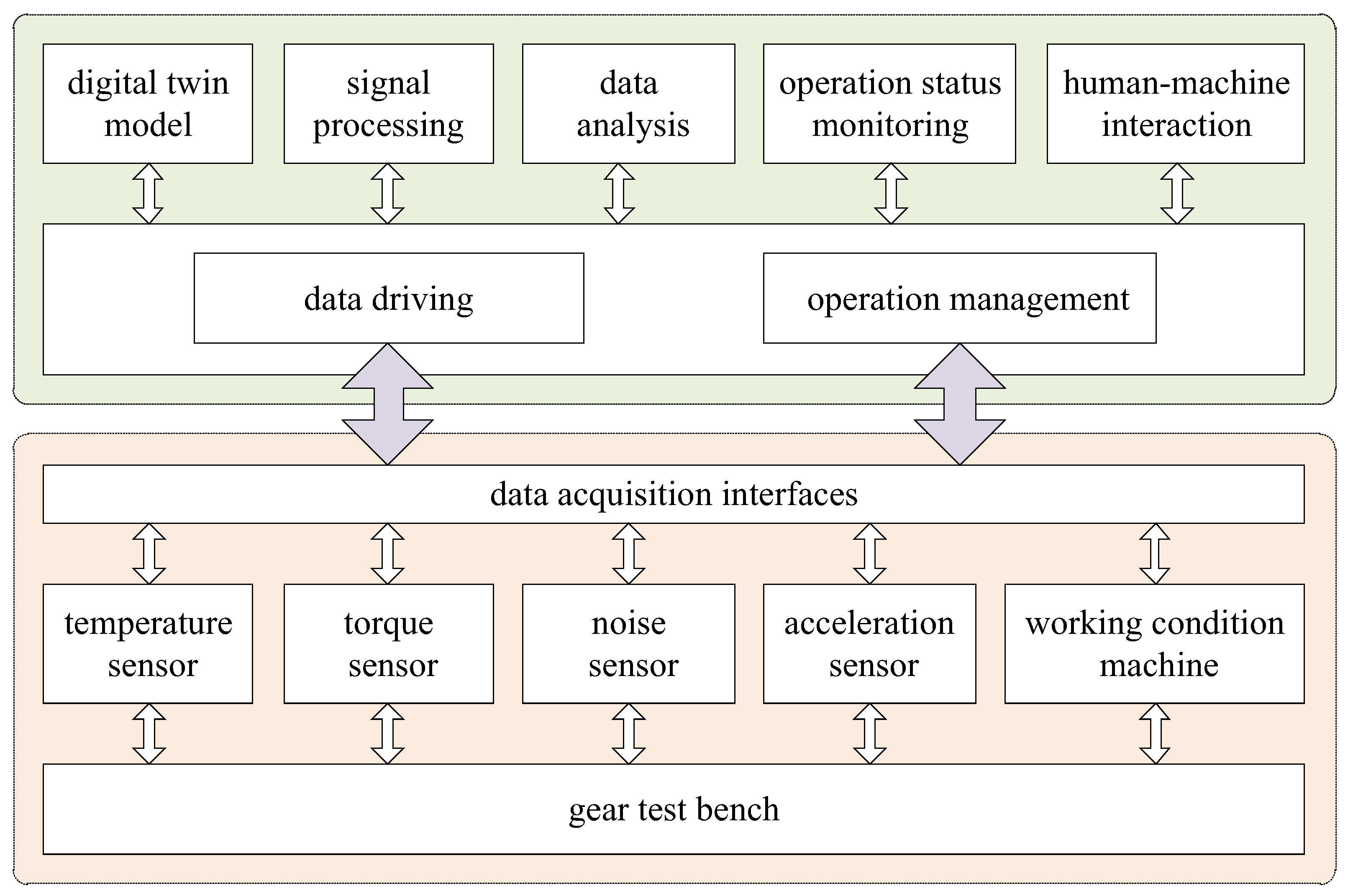
2. Construction of the State Monitoring System of the Gear Test Bench Based on a Digital Twin Model

The state monitoring system of the gear test bench based on a digital twin model is composed as follows: physical information acquisition system and digital twin monitoring system, as shown in Figure 1. Here, the physical information acquisition system is composed of the gear test bench, sensors (i.e., temperature sensor, torque sensor, noise sensor, and acceleration sensor), working condition machine, data acquisition interfaces, etc. The digital twin monitoring system consists of different modules, such as data driving, operation management, human–machine interaction, digital twin model, signal processing, running state monitoring, and data analysis.
Under the normal running state, in real time, the physical information acquisition system can collect the test bench operation data and transform it into real physical quantities through sensors during the normal operation of the gear test bench. At the same time, it connects with the equipment condition machine to obtain the real-time running state of the gear test bench equipment. The physical quantities are converted into digital data by means of the data acquisition interfaces. RS-232 and other interfaces are used to collect and convert these physical data, such as temperature, noise, vibration, acceleration, etc. The operation of the digital twin monitoring system is based on the Windows operating system and developed jointly through MATLAB, SolidWorks, ADAMS, Visual C++, and other software. The management program can access the data acquisition interface through the driver in the monitoring system, so as to obtain the real-time signal of the running state of the gear test bench. The signal processing module then conducts the acquired raw signals and maps the processed data to a digital twin model. In the end, the data analysis module can analyze the collected data and extract the data features.

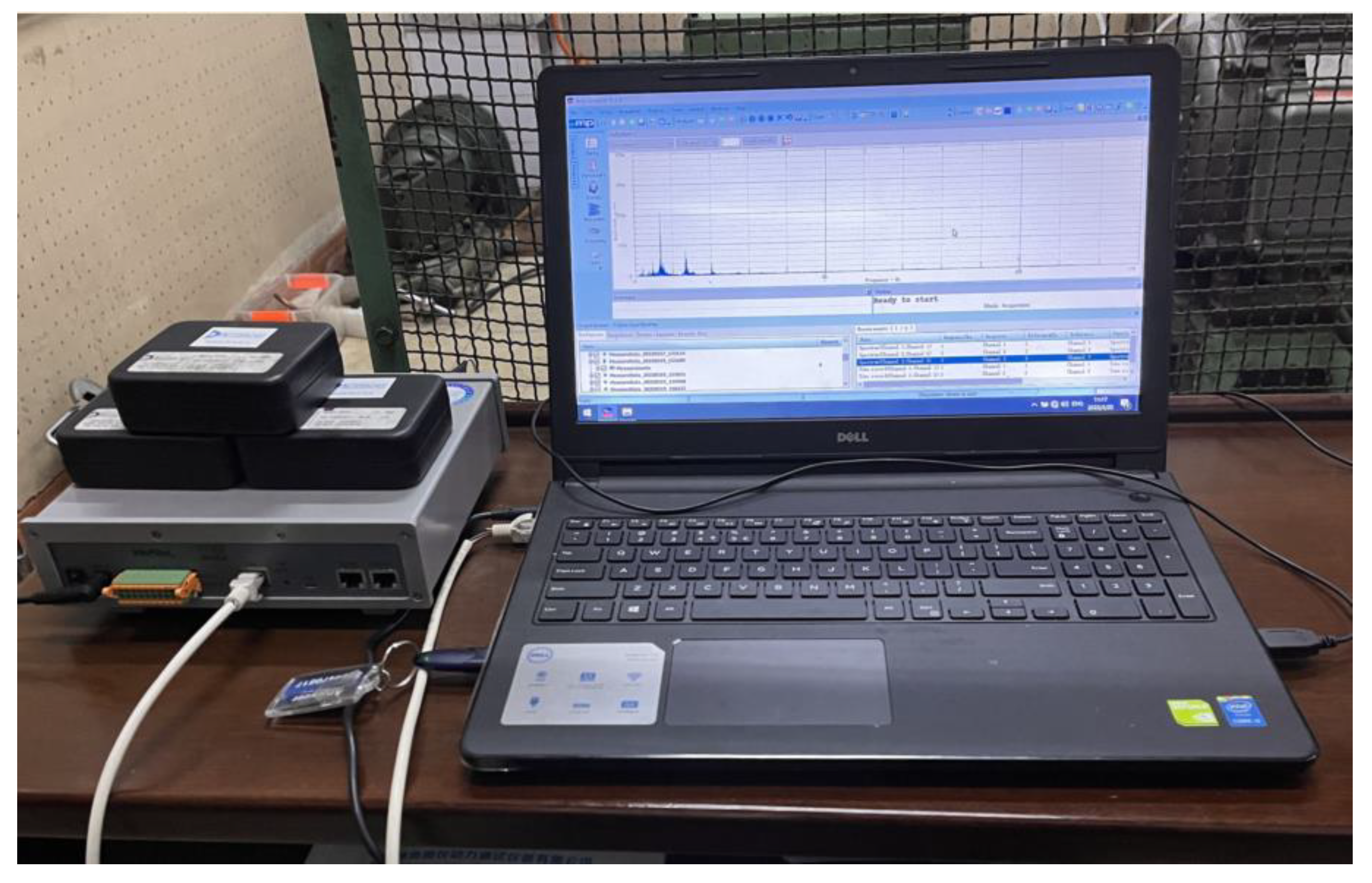
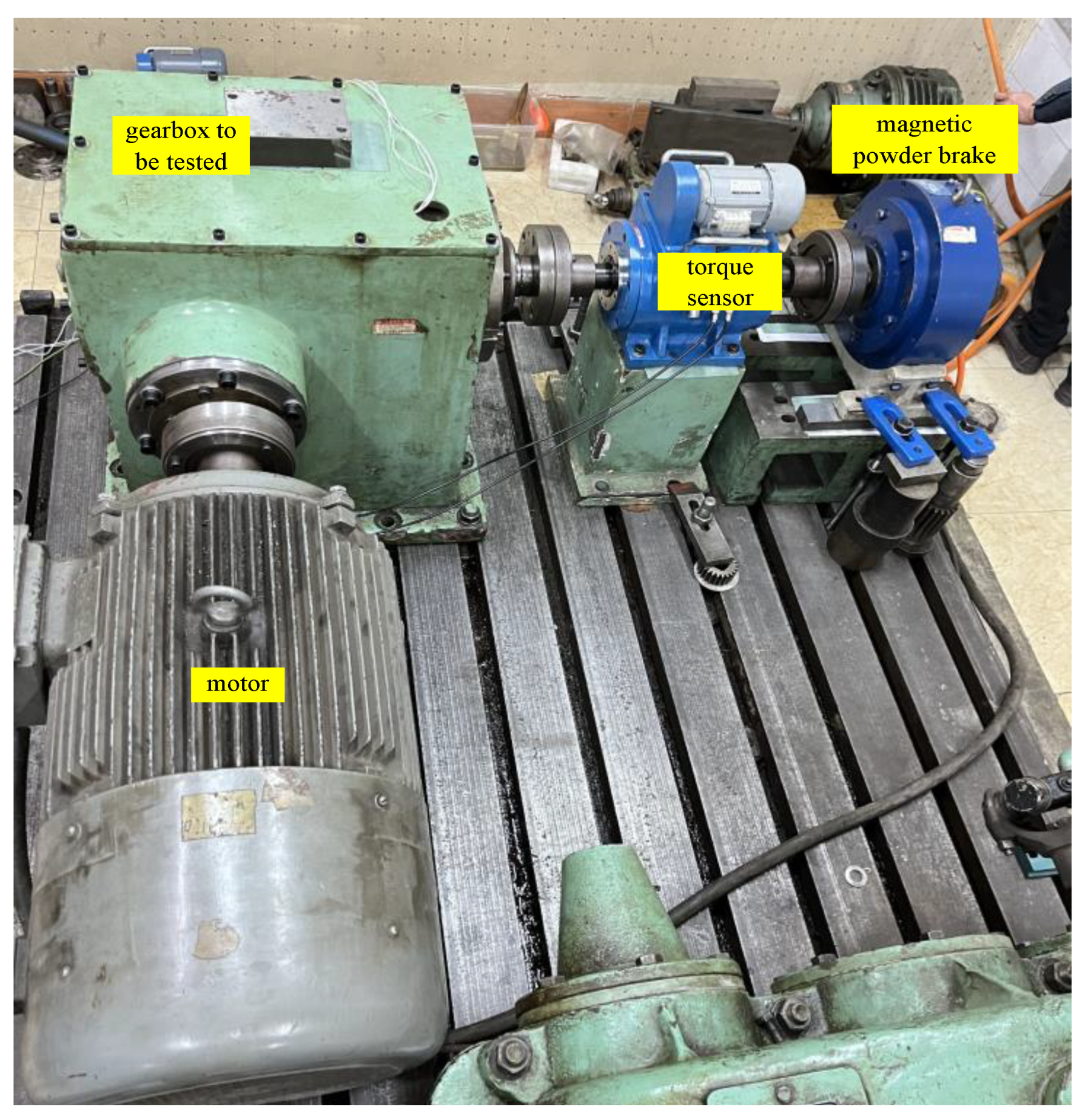
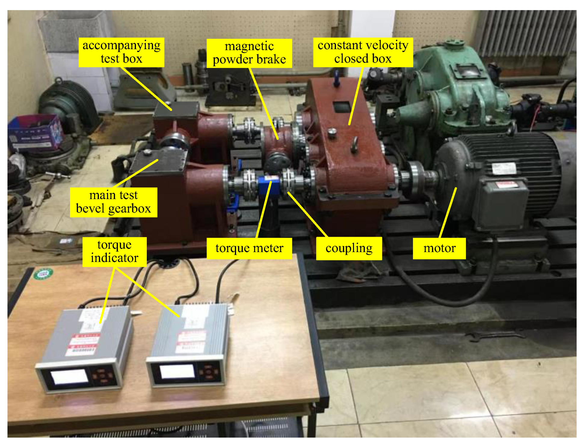
3. Physical Information Acquisition of Gear Test Bench

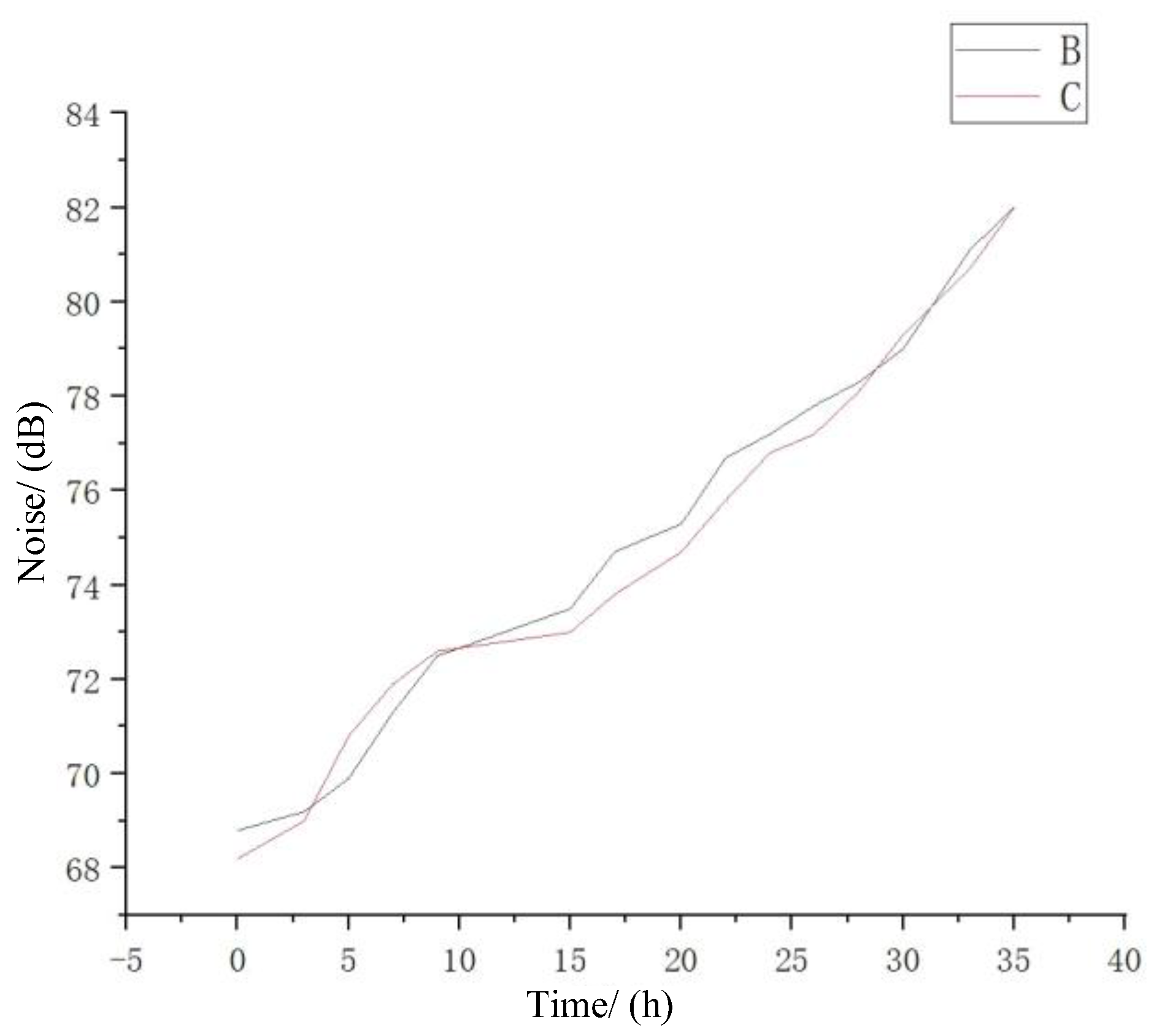
3.1. Vibration and Noise Information Acquisition of Gear Test Bench

The operation process information of the gear test bench can be reflected through the vibration signal generated during the process of the gear test equipment operation. Under the normal running state, the acquired vibration signal is smooth and free of abnormal noise, which provides a basis for monitoring the normal running state of the gear test bench. An M + P vibration tester is used in this system, which includes a data acquisition card and computer, as shown in Figure 2. A sensor with a small size, high sensitivity, and strong anti-interference ability is selected to collect vibration signals. The arrangement of sensors on the tested gearbox is shown in Figure 3. At the same time, the sensor is installed in the gearbox and the noise signal is collected by a decibel tester. Compared with the normal running state without broken gear, the abnormal operation noise will increase significantly.

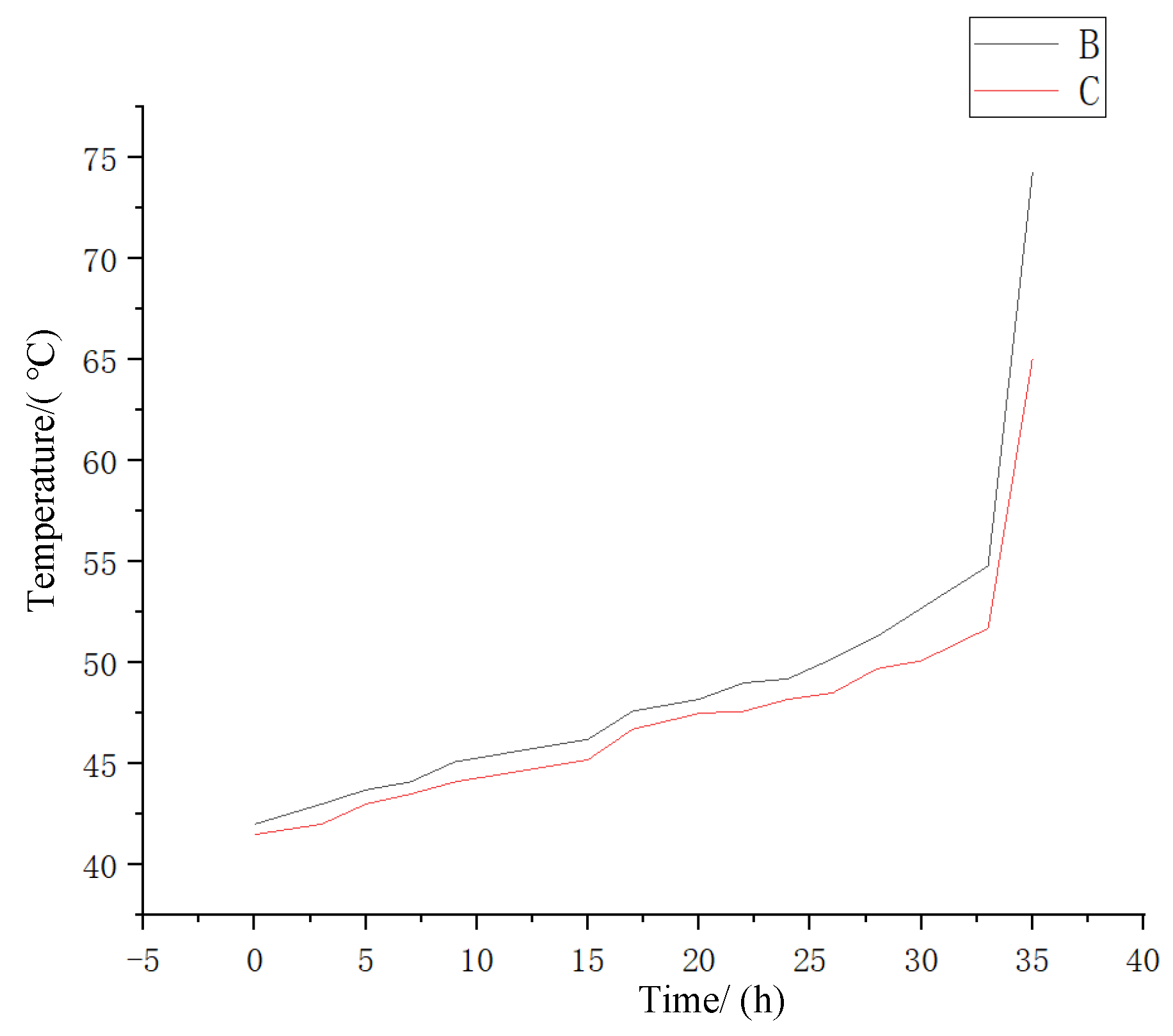
3.2. Temperature Acquisition of Gear Test Bench

During the running process of the gear test bench equipment, factors such as frictional heat and changes of laboratory temperature will result in the change of temperature of parts of the gear test bench, and the normal operation process can be disturbed. Therefore, it is necessary to measure the temperature of the gear test bench, especially the gearbox. In the gear transmission process, the generated friction heat will transfer to the gearbox and lubricating oil, causing a temperature rise of the oil. During the testing process, the lubricant temperature in the main gearbox after thermal balance shall not be higher than 80 °C, and the temperature of the main test gearbox shall not be higher than 75 °C, which is taken as the judging criteria of the gear test bench’s normal operation. During the temperature acquisition testing, an infrared temperature gun is used to measure the temperature of the main test bevel gearbox, and the normal temperature is 54.8 °C after the thermal equilibrium.

3.3. Operation Torque Information Acquisition of Gear Test Bench

The torque fluctuation of the shaft of the gear test bench reflects the changes of friction force in every direction under a normal running state. In the gear test bench, the transmission input shaft is driven by a frequency-controlled motor. By placing a torque sensor on the gear test bench and connecting it to a torque tester through a data line, the data of rotation speed and torque at the position where the torque sensor is fixed can be detected in real time. The installation diagram of the torque sensor on the gear test bench is shown in Figure 4.

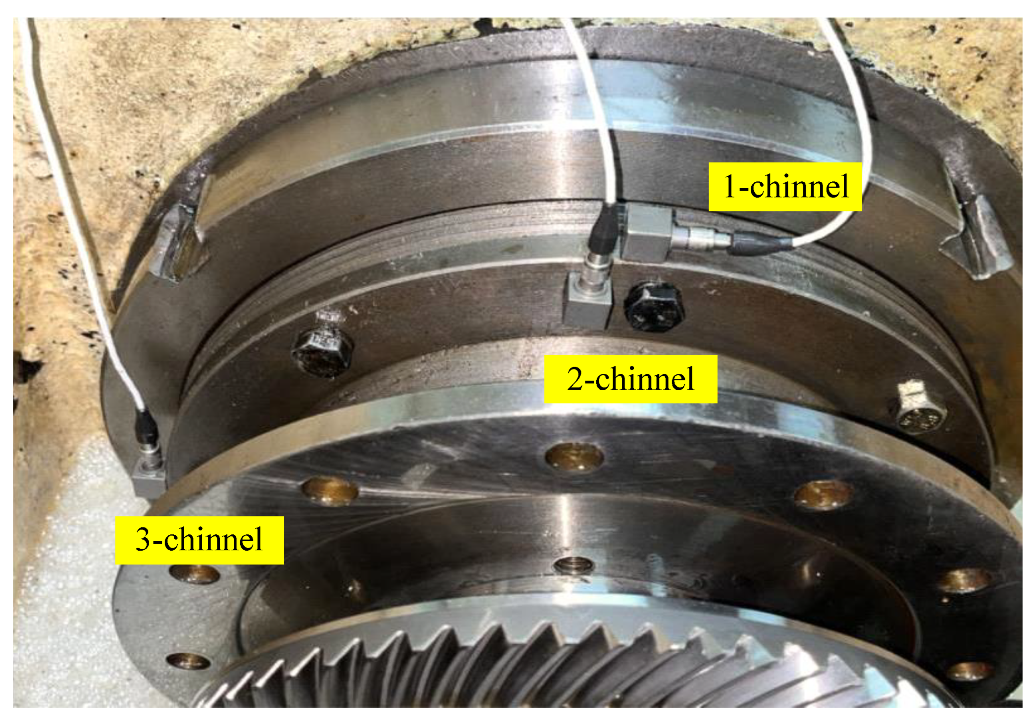
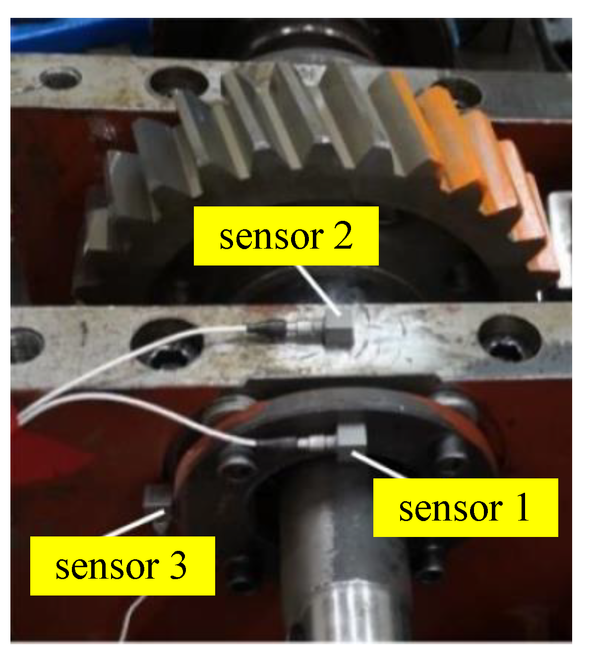
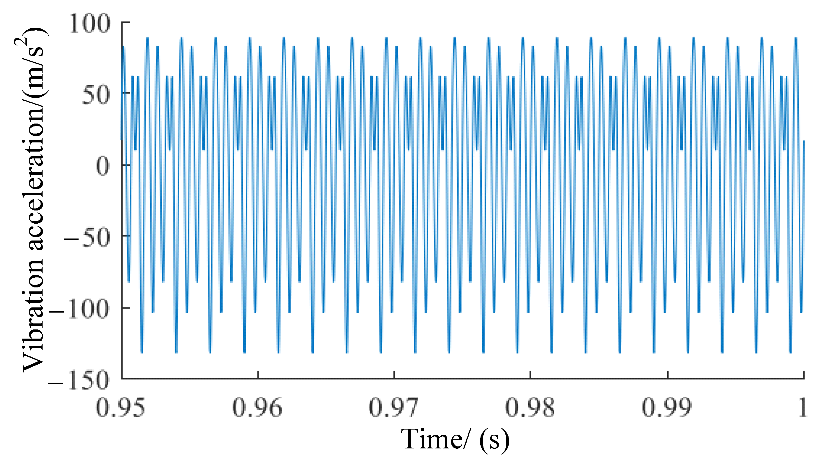
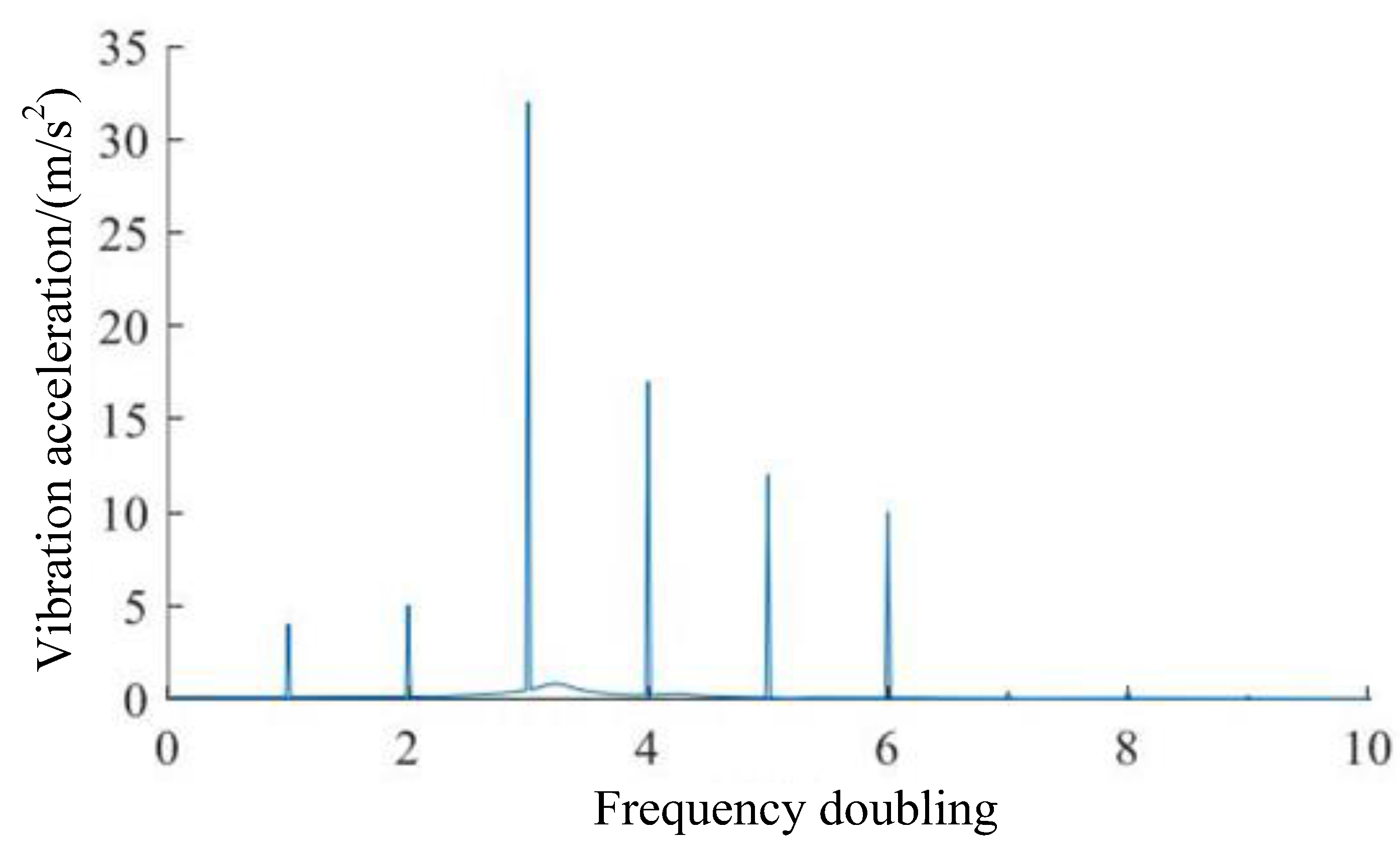
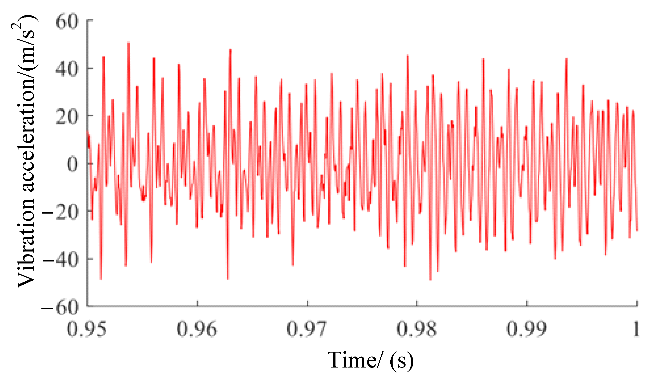
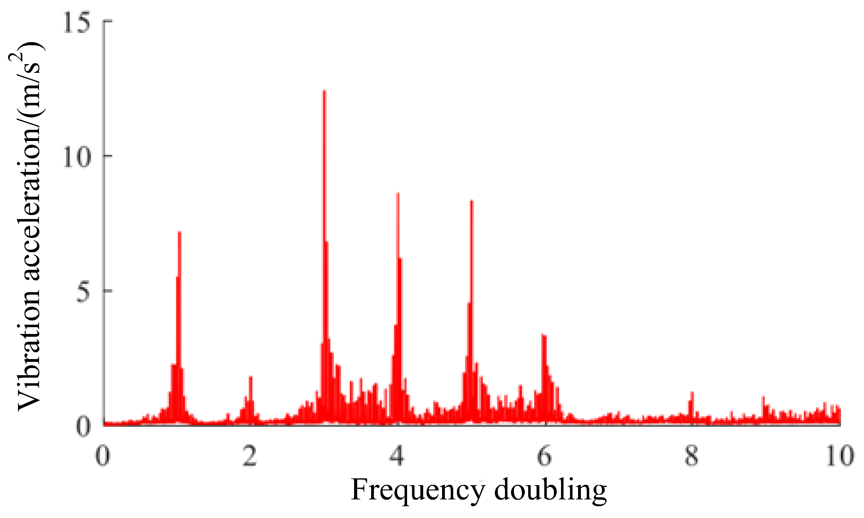
3.4. Vibration Acceleration Signal Acquisition

In the gear test bench, three acceleration sensors are used to extract the vibration response of the gear in the vertical, lateral, and axial directions, respectively, which are fixed at the output end cover and the upper surface of the gearbox. The synthesis data of the three sampled signals are approximately regarded as the vibration acceleration. The positions of the acceleration sensors are shown in Figure 5. Sensors 1, 2, and 3 correspond to the axial, vertical, and lateral directions, respectively. The gear test bench is connected to the computer by the working condition machine, which supports the running state monitoring of the equipment and the data collection of the physical information (e.g., speed, temperature, noise, and working mode) of the gear test bench through the communication protocol.

4. Digital Twin Monitoring System Development

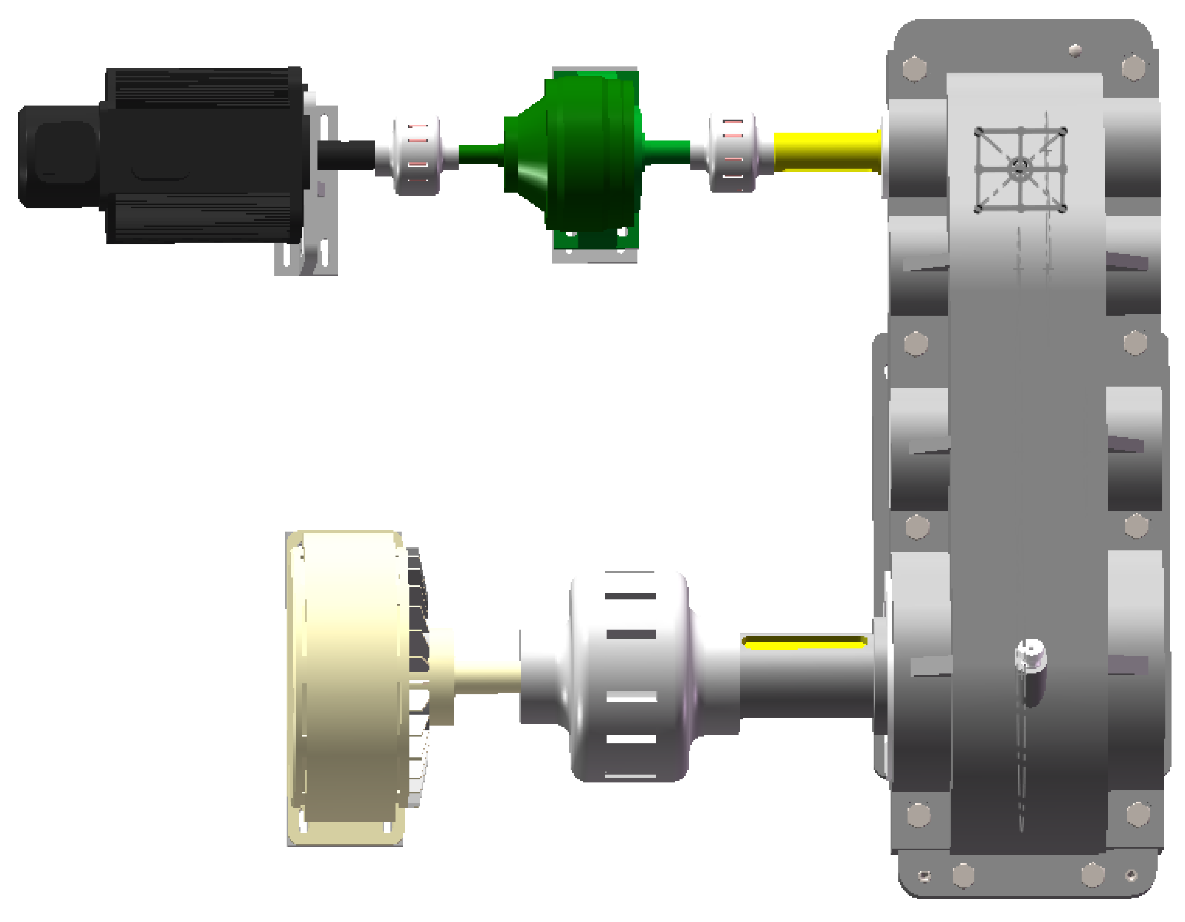
4.1. Geometric Model Construction of Gear Test Bench

All parts of the gear test bench equipment are modeled and assembled in SolidWorks. In order to display the visualization effect of the equipment, 3ds Max software is used to render the equipment by selecting the appropriate materials and rendering the model of the gear test bench. The model after the modeling and rendering operation is as consistent as possible with the real equipment to meet the requirement of realness. Meanwhile, the gear test bench model can also be imported into Unity3D software for the visualization settings. The gear test bench model is shown in Figure 6.

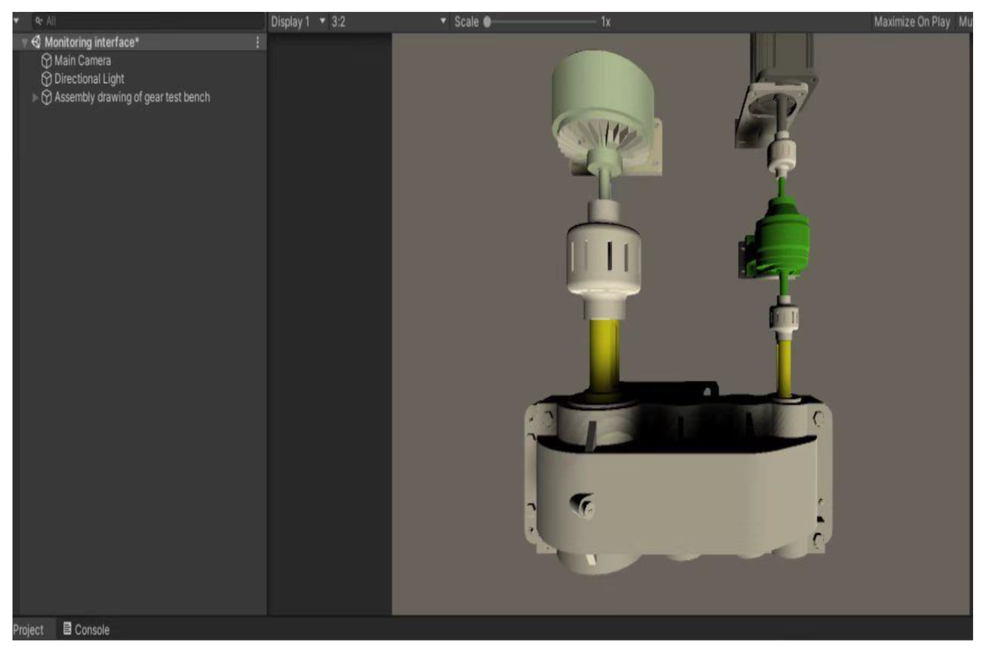
4.2. Simulation Environment Creation of Gear Test Bench

In order to map the normal operation data of the gear test bench to the digital twin model and increase the system operation speed, the geometry model of the gear test bench is lightened by means of the existing digital twin system development platform. A server is arranged in the relevant equipment of the actual gear laboratory to find the source data of the gear test bench by means of the function of address search, lookup, etc. When the gear test bench is in a normal running state, once its information is obtained, the server will summarize the collected testing data and store it into the database as soon as possible. The data-driven engine function embedded in Unity3D software is used to conduct the logical data. With the help of the data-driven engine, the running state parameters of the gear test bench can be obtained from the database through the logic layer and imported into the digital twin model for system driving, and the synchronous movement simulation between the digital twin model and the real-time monitoring of the equipment operation can be realized. Finally, the real-time information of the equipment can be displayed in three dimensions, with the digital twin interface of the gear test bench shown in Figure 7. In addition, after several tests of actual operation effects, the animation running effect is smooth, the human–machine interaction is timely, and the digital twin model is stable and reliable, which is almost the same as the actual gear test bench running state in the laboratory.

4.3. Implementation of Digital Twin Monitoring System

In the digital twin monitoring system, the recurring iterative update method is applied to ensure the running state of the digital twin model is consistent with that of the actual gear test bench in the laboratory. Firstly, the original running state data of the gear test bench can be read by calling the digital twin monitoring system driver. The conversion of physical quantities and curve fitting of the read data can then be realized in the signal processing module, and the visualization of the digital twin model can finally be achieved through the human–computer interaction interface. Furthermore, combined with ADAMS software, the dynamic motion state of the digital twin model can be observed, and the dynamic performance visualization can be displayed through the user interface of the digital twin monitoring system. The time domain and frequency domain variation results of simulation vibration are shown in Figure 8 and Figure 9, respectively.

5. Test Verification

In this paper, a closed-power flow fatigue life test bench of spiral bevel gears, which is mainly composed of a motor, constant velocity closed box, magnetic power brake, accompanying test box, main test bevel gearbox, torque meter, torque indicator, etc., is designed and assembled. The simulation effectiveness of the proposed state monitoring system is illustrated and verified by physical quantities such as vibration, noise, and temperature in the running process of the gear test bench. The material of the gearbox is ductile iron, which has the characteristics of better support stiffness. In the test, a pair of spiral bevel gears is used as the experimental object. The magnetic powder brake, main test bevel gearbox, coupling, and motor compose a closed transmission loop. According to the design standard and working range of the gear test bench, the brake torque loaded on the gear is set at 499 N.m, and the driving speed of the pinion is set at 720 r/min. The vibration signal is collected by an M + P vibration tester and the noise is collected by a decibel tester, while the temperature is measured and recorded by an infrared thermometer. The geometric parameters of the testing spiral bevel gears are shown in Table 1, while the test bench of spiral bevel gear fatigue life is shown in Figure 10.
The test process is as follows: firstly, the gear meshing running time is half an hour under one-fourth, one-half, three-fourths, and full of the brake torque, respectively. The start time of the experiment is then recorded. During the test operation periods with different brake torques, the sensors fixed in the gearbox can collect the signals, such as the temperature, noise, vibration. The data collection process is continuous until the gear tooth is broken. During the test, factors such as the tooth surface wear, extrusion, and insufficient lubrication in the gearbox will cause the rise of the gearbox temperature. The defects (e.g., tooth defect, tooth shape errors, gear tooth offset load, and insufficient bearing preload) in the gearbox can cause the edge contact on the tooth surface and the gear circumferential vibration. At the same time, under the action of alternating stress, the noise of gear mesh will be increased and the crack of the tooth will be gradually expanded, resulting in the final fracture of the tooth and the stop of the gear test bench.
Under the normal running state, the temperature and noise changes during the operation of the gear test bench equipment are shown in Figure 11 and Figure 12, respectively. More specifically, a temperature comparison between the gear test bench equipment operation and the state monitoring system simulation is shown in Figure 11, where Curves B and C represent the temperature change of the gear test bench and the state monitoring system, respectively.
It is clear that the temperature of the gearbox gradually increases from the beginning of the test. When the temperature of the box reaches about 55 °C, the crack of the broken tooth begins to occur. After that, the temperature of the gearbox rises sharply. When the temperature reaches about 75 °C, the running state of the gearbox appears abnormal and the tooth broken phenomenon occurs. The trend of noise comparison between the gear test bench equipment operation and the state monitoring system simulation is shown in Figure 12, where Curves B and C represent noise changes of the gear test bench and the state monitoring system, respectively. It can be seen that the noise gradually increases from the beginning of the test, the tooth is broken when the noise gradually increases to about 82 dB, and the gear test bench stops running at the same time.
Meanwhile, the visualized dynamic information is displayed in the state monitoring system. The time domain and frequency domain variation results of the equipment vibration under the fixed load and speed are shown in Figure 13 and Figure 14, respectively, which are collected by an M + P vibration tester under the normal running state.
By comparing Figure 8 with Figure 13 and Figure 9 with Figure 14, respectively, it can be seen that the vibration variation trends of the gear test bench equipment operation are basically identical to their of the state monitoring system simulation, which both in the time domain and the frequency domain. Under the normal running state with fixed load and speed, the vibration time domain diagram of the equipment is a stable waveform from the beginning to the tooth broken. The vibration frequency domain diagram is approximately a normal distribution, reaching a peak at the 3rd frequency doubling and then gradually declining.
In the frequency domain, both in the test and simulation results, the maximum peak value of vibration acceleration occurs at the 3rd frequency doubling, with the larger peaks mainly occurring at the 4th, 5th, and 6th frequency doubling. Meanwhile, in contrast to the simulation results, there is a high peak of the fundamental frequency in the test results, which is due to the impact of the load and speed fluctuations. In the time domain, the vibration curves of the test and simulation have similar characteristics. In the test results, there have more harmonics and the curves are more chaotic. Relatively, the time domain curves are more regular in the simulation results because there has been no consideration of the complex external factors.
The complete results of the monitoring test verify the correctness and practicability of the proposed state monitoring system, which really realized the state monitoring of the gear test bench running process based on digital twin. Furthermore, by changing the different braking torques and driving speeds, many other gear test bench running state monitoring experiments have been carried out, and the correctness and practicability of the proposed monitoring system have also been proved from the experimental results.

6. Discussion

In this paper, digital twin technology is applied to the field of running state monitoring in the gear experiment process, to make up for the deficiency that the traditional running state monitoring cannot meet the gear test bench dynamic requirements of the experiment process. By establishing a state monitoring system of the gear test bench based on a digital twin model, the running state of the gear test bench under normal working conditions is simulated in real time, and the integration and visualization of the various experimental monitoring data is realized, which lays a foundation for further research on the running state monitoring, fault diagnosis, and system maintenance of the gear test bench. During the test, various factors (e.g., tooth surface wear, extrusion, and insufficient lubrication) and defects (e.g., tooth defect, tooth shape errors, gear tooth offset load, and insufficient bearing preload) in the gearbox will cause regular changes in the working parameters (e.g., vibration, temperature, and noise) of the gearbox, which reflect the working state of the entire gear test bench. For example, from the beginning of the test, the temperature of the gearbox gradually increases, and the noise gradually increases. When the temperature of the box reaches about 55 °C, the crack of the broken tooth begins to occur. The temperature of the gearbox then rises sharply. When the temperature reaches about 75 °C, the noise reaches about 82 dB, the running state of the gearbox appears abnormal, the tooth broken phenomenon occurs, and the gear test bench stops running. Through observing the verification results of the whole process of the gear fatigue test, it is concluded that the proposed state monitoring system can be applied to the running state monitoring and the performance prediction of the gear test bench.
In this paper, the data acquisition and monitoring during the normal operation process of the gear test bench only involved the temperature, noise, and vibration. In the actual operation of the equipment, more sensors need to be installed for comprehensive data collection. Only by expanding the data collection and monitoring of various influencing factors, improving the efficiency of data collection and processing, and strengthening the function of the state monitoring system based on digital twin can the running state of equipment be monitored more effectively.
Next, researchers will continue to promote the evaluation, implementation, and application of this state monitoring system. They will verify the practicability of the evaluation method with as many types of operational status monitoring as possible, so as to enhance the persuasiveness of the theory. Furthermore, efforts are also being made to study the deep mining and analysis of the digital twin data, so as to provide a data basis for intelligent decisions (e.g., running state evaluation, fault diagnosis of equipment) and improve the service function of the state monitoring system based on a digital twin model.

7. Conclusions

In this paper, a digital twin-based state monitoring method of the gear test bench is proposed, and the state monitoring system of the gear test bench based on a digital twin model is constructed. By comparing the test and simulation results, the correctness and practicability of the proposed state monitoring system is verified, which really realized the state monitoring of the gear test bench running process based on a digital twin model. The main conclusions are as follows:
In this paper, digital twin technology is first applied to timely and effectively monitor the running state of the gear test bench, which makes the digital condition monitoring of the gear test bench possible, as well as improving the equipment monitoring efficiency and reducing the running monitoring cost.
Normal operation data of the gear test bench can be accurately and timely collected by the proposed state monitoring system. At the same time, the running law of the gear test bench can be reflected by the analysis and processing of the collected data, and the state monitoring for the gear test bench operation is achieved.
The temperature and noise variation trends of the gear test bench equipment operation are basically identical to that of the proposed state monitoring system simulation. The temperature and noise of the gearbox gradually increase from the beginning of the test. When the temperature reaches about 75 °C, the noise reaches about 82 dB, the running state of the gearbox appears abnormal, and the tooth broken phenomenon occurs.
The vibration variation trends of the gear test bench equipment operation are basically identical to that of the proposed state monitoring system simulation. Under the normal running state with fixed load and speed, the vibration time domain diagram of the equipment is a stable waveform from the beginning to the tooth broken. The vibration frequency domain diagram is approximately a normal distribution, which reaches its peak at the 3rd frequency doubling and then gradually declines.
The proposed state monitoring system provides a new idea and reliable solution for the dynamic monitoring, further fault diagnosis, and performance prediction of the gear test bench.

Author Contributions

Conceptualization, J.L.; investigation, S.W. and J.L.; methodology, S.W. and J.L.; software, S.W.; validation, H.Z. (Huijie Zhang), H.Z. (Hengbo Zhao), and S.W.; writing—original draft preparation, S.W.; writing—review and editing, J.Y. and J.L. All authors have read and agreed to the published version of the manuscript.

Funding

This research was funded by the National Natural Science Foundation of China (Grant nos. 51405135, 52275054).

Institutional Review Board Statement

Not applicable.

Informed Consent Statement

Not applicable.

Data Availability Statement

Not applicable.

Acknowledgments

The authors would like to thank all the authors of the references that gave us inspiration and help. The authors are grateful to the editors and anonymous reviewers for their valuable comments that improved the quality of this paper.

Conflicts of Interest

The authors declare no conflict of interest.

References

  1. Jin, X.Y.; Zhang, T.F.; Zhao, L.L.; Zhang, L.; Wang, Y.J. Vibration mode of gearbox in test bed of gear with intersecting axis. Appl. Mech. Mater. 2012, 121, 1779–1783. [Google Scholar] [CrossRef]
  2. Forstinger, M.; Bauer, R.; Hofer, A.; Rossegger, W. Multivariable control of a test bed for differential gears. Control Eng. Pract. 2016, 57, 18–28. [Google Scholar] [CrossRef]
  3. Wunsch, A.; Tsay, D.M.; Vajna, S.; Schabacker, M. A New Approach for Designing A Gearbox for A New Kind of Independently Controllable Transmissions. In Proceedings of the ASME International Design Engineering Technical Conferences and Computers and Information in Engineering Conference (IDETC/CIE 2013), Portland, OR, USA, 4–7 August 2013. V03AT03A008. [Google Scholar]
  4. Reddy, B.S.; Mahato, K.K. Calculation, design and analysis of two stage single speed gearbox for all terrain vehicle for baja sae. Mater. Today Proc. 2021, 46, 7187–7203. [Google Scholar] [CrossRef]
  5. Kim, J.T.; Lee, H.S.; Park, J.H.; Woo, J.K.; Choi, I.S.; Kim, Y.K.; Cho, S.J.; Ha, C.S.; Park, Y.J. Maize harvester gearbox design modification for improved fatigue life. Sci. Rep. 2022, 12, 15576. [Google Scholar] [CrossRef] [PubMed]
  6. Zhang, S.R.; Wang, L.J.; Du, X.J.; Jin, H.; Zhang, Y.H.; Sun, X.Y.; Zhang, B.Y.; Li, Y.X.; Wei, J.; Zhang, J.L.; et al. Research of Fatigue Life Prediction for Optimization of the Gearbox Design Based on MSC.Patran. Strength Mater. 2021, 53, 636–645. [Google Scholar] [CrossRef]
  7. Strakosch, F.; Nikoleizig, H.; Derbel, F. Analysis and Evaluation of Vibration Sensors for Predictive Maintenance of Large Gears with an Appropriate Test Bench. In Proceedings of the IEEE International Instrumentation and Measurement Technology Conference (I2MTC), Glasgow, UK, 17–20 May 2021. [Google Scholar] [CrossRef]
  8. Lopez de Calle, K.; Ferreiro, S.; Roldan-Paraponiaris, C.; Ulazia, A. A Context-Aware Oil Debris-Based Health Indicator for Wind Turbine Gearbox Condition Monitoring. Energies 2019, 12, 3373. [Google Scholar] [CrossRef] [Green Version]
  9. Salameh, J.P.; Cauet, S.; Etien, E.; Sakout, A.; Rambault, L. Gearbox condition monitoring in wind turbines: A review. Mech. Syst. Signal Pract. 2018, 111, 251–264. [Google Scholar] [CrossRef]
  10. Manarikkal, I.; Elasha, F.; Mba, D. Diagnostics and prognostics of planetary gearbox using CWT, auto regression (AR) and K-means algorithm. Appl. Acoust. 2021, 184, 108314. [Google Scholar] [CrossRef]
  11. Zhang, K.; Tang, B.P.; Deng, L.; Liu, X.L. A hybrid attention improved ResNet based fault diagnosis method of wind turbines gearbox. Measurement 2021, 179, 109491. [Google Scholar] [CrossRef]
  12. He, Z.Y.; Shao, H.D.; Wang, P.; Lin, J.; Cheng, J.S.; Yang, Y. Deep transfer multi-wavelet auto-encoder for intelligent fault diagnosis of gearbox with few target training samples. Knowl-Based. Syst. 2020, 191, 105313. [Google Scholar] [CrossRef]
  13. Azamfar, M.; Singh, J.; Bravo-Imaz, I.; Lee, J. Multisensor data fusion for gearbox fault diagnosis using 2-D convolutional neural network and motor current signature analysis. Mech. Syst. Signal. Pract. 2020, 144, 106861. [Google Scholar] [CrossRef]
  14. Brethee, K.F.; Ibrahim, G.R.; Mohammed, R.A.; Albarbar, A.H. Diagnosis of Induced Gear Wear in Two-Stage Helical Gearbox Based on Vibration Analysis. In Proceedings of the 2020 13th International Conference on Developments in eSystems Engineering (DESE 2020), Electr Network, 13–17 December 2020; pp. 233–238. [Google Scholar] [CrossRef]
  15. Cao, W.; Wang, W.J.; Wang, R. Wear Trend Prediction of Gearbox Based on Oil Monitoring Technology. Adv. Mater. Res. 2012, 411, 576–579. [Google Scholar] [CrossRef]
  16. Saucedo-Dorantes, J.J.; Delgado-Prieto, M.; Osornio-Rios, R.A.; Romero-Troncoso, R.D. Diagnosis methodology for identifying gearbox wear based on statistical time feature reduction. Proc. Inst. Mech. Eng. Part C J. Mech. Eng. Sci. 2018, 232, 2711–2722. [Google Scholar] [CrossRef] [Green Version]
  17. Zivkovic, P.; Ognjanovic, M.; Camagic, I.; Jovanovic, M.; Kalaba, D.; Tomic, R.; Grgic, I. Assessment of Probability of Gear Tooth Side Wear of a Planetary Gearbox. Teh. Vjesn. 2020, 27, 506–512. [Google Scholar] [CrossRef]
  18. Cao, W.; Zhang, H.; Wang, N.; Wang, H.W.; Peng, Z.X. The gearbox wears state monitoring and evaluation based on on-line wear debris features. Wear 2019, 426, 1719–1728. [Google Scholar] [CrossRef]
  19. Wang, C.; Wang, S.R.; Wang, G.Q. A method for calculating gear meshing efficiency by measured data from gear test machine. Measurement 2018, 119, 97–101. [Google Scholar] [CrossRef]
  20. Wan, X.; Wang, D.; Tse, P.W.; Xu, G.H.; Zhang, Q. A Critical Study of Different Dimensionality Reduction Methods for Gear Crack Degradation Assessment Under Different Operating Conditions. Measurement 2016, 78, 138–150. [Google Scholar] [CrossRef]
  21. Villa, L.F.; Renones, A.; Peran, J.R.; de Miguel, L.J. Statistical fault diagnosis based on vibration analysis for gear test-bench under non-stationary conditions of speed and load. Mech. Syst. Signal. Pract. 2012, 29, 436–446. [Google Scholar] [CrossRef]
  22. Brovkova, M.; Molodtsov, V.; Bushuev, V. Implementation specifics and application potential of digital twins of technological systems. Int. J. Adv. Manuf. Technol. 2021, 117, 2279–2286. [Google Scholar] [CrossRef]
  23. Lopez, C.E.B. Real-time event-based platform for the development of digital twin applications. Int. J. Adv. Manuf. Technol. 2021, 116, 835–845. [Google Scholar] [CrossRef]
  24. Grieves, M. Digital twin: Manufacturing excellence through virtual factory replication. White Paper 2014, 1, 1–7. [Google Scholar]
  25. Xiao, J.Y.; Fan, K.G. Research on the digital twin for thermal characteristics of motorized spindle. Int. J. Adv. Manuf. Technol. 2022, 119, 5107–5118. [Google Scholar] [CrossRef]
  26. Zhang, R.; Wang, F.; Cai, J.; Wang, Y.; Guo, H.F.; Zheng, J.S. Digital twin and its applications: A survey. Int. J. Adv. Manuf. Technol. 2022, 123, 4123–4136. [Google Scholar] [CrossRef]
  27. Xu, J.T.; Guo, T.J. Application and research on digital twin in electronic cam servo motion control system. Int. J. Adv. Manuf. Technol. 2021, 112, 1145–1158. [Google Scholar] [CrossRef]
  28. Guo, H.F.; Zhu, Y.X.; Zhang, Y.; Ren, Y.P.; Chen, M.S.; Zhang, R. A digital twin-based layout optimization method for discrete manufacturing workshop. Int. J. Adv. Manuf. Technol. 2021, 112, 1307–1318. [Google Scholar] [CrossRef]
  29. Hu, Z.; Fang, X.; Zhang, J. A digital twin-based framework of manufacturing workshop for marine diesel engine. Int. J. Adv. Manuf. Technol. 2021, 117, 3323–3342. [Google Scholar] [CrossRef]
  30. Kong, T.X.; Hu, T.L.; Zhou, T.T.; Ye, Y.X. Data construction method for the applications of workshop digital twin system. J. Manuf. Syst. 2021, 58, 323–328. [Google Scholar] [CrossRef]
  31. Tao, F.; Sui, F.; Liu, A.; Qi, Q.; Zhang, M.; Song, B.; Guo, Z.; Lu, S.C.Y.; Nee, A.Y.C. Digital twin-driven product design framework. Int. J. Prod. Res. 2019, 57, 935–3953. [Google Scholar] [CrossRef] [Green Version]
  32. Qi, Q.L.; Tao, F. Digital twin and big data towards smart manufacturing and industry 4.0: 360 degree comparison. IEEE Access. 2018, 6, 3585–3593. [Google Scholar] [CrossRef]
  33. Qi, Q.L.; Tao, F.; Zuo, Y.; Zhao, D.M. Digital twin service towards smart manufacturing. Procedia CIRP 2018, 72, 237–242. [Google Scholar] [CrossRef]
  34. Liu, Z.; Zhang, Q.L.; Duan, J.G.; Liu, D. Digital twin-based testing process management for large and complex equipment components. Int. J. Adv. Manuf. Technol. 2022, 121, 3143–3161. [Google Scholar] [CrossRef]
  35. Liu, Z.; Chen, W.; Zhang, C.X.; Yang, C.B.; Chu, H.Y. Data Super-Network Fault Prediction Model and Maintenance Strategy for Mechanical Product Based on Digital Twin. IEEE Access. 2019, 7, 177284–177296. [Google Scholar] [CrossRef]
  36. Aivaliotis, P.; Georgoulias, K.; Chryssolouris, G. The use of Digital Twin for predictive maintenance in manufacturing. Int. J. Comput. Integr. Manuf. 2019, 32, 1067–1080. [Google Scholar] [CrossRef]
  37. Nguyen, T.N.; Ponciroli, R.; Bruck, P.; Esselman, T.C.; Rigatti, J.A.; Vilim, R.B. A digital twin approach to system-level fault detection and diagnosis for improved equipment health monitoring. Ann. Nucl. Energy 2022, 170, 109002. [Google Scholar] [CrossRef]
  38. Tao, F.; Zhang, M.; Liu, Y.; Nee, A.Y.C. Digital twin driven prognostics and health management for complex equipment. Cirp. Ann. 2018, 67, 169–172. [Google Scholar] [CrossRef]
  39. Li, Q.W.; Jiang, P.; Li, H. Prognostics and health management of FAST cable-net structure based on digital twin technology. Res. Astron. Astrophys. 2020, 20, 067. [Google Scholar] [CrossRef]
  40. Krishnan, M.; Venkatesan, S.; Nagendran, V.; Tengenkai, N. Health monitoring and prognosis of electric vehicle motor using intelligent-digital twin. IET Electr. Power. Appl. 2019, 13, 1328–1335. [Google Scholar] [CrossRef]
  41. He, B.; Liu, L.; Zhang, D. Digital twin-driven remaining useful life prediction for gear performance degradation: A Review. J. Comput. Inf. Sci. Eng. 2021, 21, 030801. [Google Scholar] [CrossRef]
  42. He, B.; Li, T.; Xiao, J. Digital twin-driven controller tuning method for dynamics. J. Comput. Inf. Sci. Eng. 2021, 21, 031010. [Google Scholar] [CrossRef]
  43. Yang, X.; Ran, Y.; Zhang, G.B.; Wang, H.W.; Mu, Z.Y.; Zhi, S.G. A digital twin-driven hybrid approach for the prediction of performance degradation in transmission unit of CNC machine tool. Robot. Comput.-Int. Manuf. 2022, 73, 102230. [Google Scholar] [CrossRef]
  44. Zhu, D.; Li, Z.; Hu, N. Multi-Body Dynamics Modeling and Analysis of Planetary Gearbox Combination Failure Based on Digital Twin. Appl. Sci. 2022, 12, 12290. [Google Scholar] [CrossRef]
  45. Lee, Y.H.; Fong, Z.H. Study on building digital-twin of face-milled hypoid gear from measured tooth surface topographical data. J. Mech. Design. 2020, 142, 113401. [Google Scholar] [CrossRef]
  46. Zhang, L.; Liu, J.H.; Wu, X.Q.; Zhuang, C.B. Digital Twin-Based Dynamic Prediction of Thermomechanical Coupling for Skiving Process. Int. J. Adv. Manuf. Technol. 2022, 1–18. [Google Scholar] [CrossRef]
  47. Lei, D.C.; Rong, K.B.; Song, B.Y.; Ding, H.; Tang, J.Y. Digital twin modeling for tooth surface grinding considering low-risk transmission performance of non-orthogonal aviation spiral bevel gears. ISA Trans. 2022, 128, 646–663. [Google Scholar] [CrossRef] [PubMed]
  48. Rong, K.B.; Ding, H.; Kong, X.N.A.; Huang, R.; Tang, J.Y. Digital twin modeling for loaded contact pattern-based grinding of spiral bevel gears. Adv. Eng. Inform. 2021, 49, 101305. [Google Scholar] [CrossRef]
  49. Yin, P.L.; Han, F.B.; Wang, J.H.; Lu, C.X. Influence of module on measurement uncertainty of gear tooth profile deviation on gear measuring center. Measurement 2021, 182, 109688. [Google Scholar] [CrossRef]
  50. Xiang, T.M.; Lan, D.D.; Zhang, S.H.; Li, W.X.; Lin, D.Q. Experimental modal test of the spiral bevel gear wheel using the PolyMAX method. J. Mech. Sci. Technol. 2018, 32, 21–28. [Google Scholar] [CrossRef]
  51. Wang, Y.Z.; Yang, K.; Tang, W. Prediction and test of stable transmission time of spiral bevel gear during a loss-of-lubrication event in helicopter transmission system. Ind. Lubr. Tribo. 2022, 74, 111–117. [Google Scholar] [CrossRef]
Figure 1. State monitoring system of the gear test bench based on a digital twin model.
Applsci 13 03291 g001
Figure 2. M + P vibration tester.
Applsci 13 03291 g002
Figure 3. Arrangement of sensors on the tested gearbox.
Applsci 13 03291 g003
Figure 4. Installation diagram of the torque sensor on the gear test bench.
Applsci 13 03291 g004
Figure 5. Position of the acceleration sensors.
Applsci 13 03291 g005
Figure 6. Gear test bench model.
Applsci 13 03291 g006
Figure 7. Digital twin interface of the gear test bench.
Applsci 13 03291 g007
Figure 8. Time domain variation results of simulation vibration.
Applsci 13 03291 g008
Figure 9. Frequency domain variation results of simulation vibration.
Applsci 13 03291 g009
Figure 10. Test bench of spiral bevel gear fatigue life.
Applsci 13 03291 g010
Figure 11. Temperature comparison between the gear test bench equipment operation and the state monitoring system simulation.
Applsci 13 03291 g011
Figure 12. Trend of noise comparison between the gear test bench equipment operation and the state monitoring system simulation.
Applsci 13 03291 g012
Figure 13. Time domain variation result of the equipment vibration under the fixed load and speed.
Applsci 13 03291 g013
Figure 14. Frequency domain variation result of the equipment vibration under the fixed load and speed.
Applsci 13 03291 g014
Table 1. Geometric parameters of the testing spiral bevel gears.
ItemsPinionGear
Number of teeth1627
Module (mm)4.254.25
Mean spiral angle (°)3535
Normal pressure angle (°)2020
Shaft angle (°)9090
Face width (mm)1717
Hand of spiral (°)LeftRight
Outer cone distance (mm)66.69366.693
Pitch angle (°)30.650759.493
Face angle (°)35.350162.2168
Root angle (°)27.783254.6499
Addendum (mm)4.6822.542
Dedendum (mm)3.3425.482
Whole tooth height (mm)8.0248.024
Bottom (mm)0.80.8
Disclaimer/Publisher’s Note: The statements, opinions and data contained in all publications are solely those of the individual author(s) and contributor(s) and not of MDPI and/or the editor(s). MDPI and/or the editor(s) disclaim responsibility for any injury to people or property resulting from any ideas, methods, instructions or products referred to in the content.

