1. Introduction
Due to the limitations of fully autonomous technology, there are certain shortcomings of automated robots in complex and unstructured environments. As an important research area in robotics, teleoperation robotics can combine the initiative of operators with the high precision of a robot [
1]. Telerobotics is still superior to intelligent programming methods in terms of making quick decisions and handling emergency cases [
2,
3].
However, the performance of teleoperation largely depends on the operator’s skill, and the implementation of a remote robot to perform complicated and delicate tasks is still challenging, especially when a human operator lacks training. The operator’s position errors may cause serious rigid collisions, and even slight negligence can result in unnecessary loss. Position errors may be caused by hand jitters, motion positioning errors, visual aberrations, or data processing delays in sending and receiving from relay stations. Unfortunately, due to the physiological limitations of the operator and the performance limitations of the equipment, position errors will always exist. This increases collision risk in teleoperation tasks, especially in precise assembly scenarios.
To alleviate the rigid collisions caused by position errors and increase the safety of teleoperation, researchers have proposed various high-performance control methods. To mitigate the operating errors caused by human tremors and improve the accuracy of teleoperation, Yang et al. [
4] designed a filter based on a support vector machine (SVM) for attenuating human tremors. To alleviate the rigid collisions, a novel virtual fixture generation method on a point-set implicit surface was proposed in [
5,
6,
7], and guidance virtual fixtures were generated with a robot-centric potential force field model, as further elaborated upon in [
8]. Rubagotti et al. [
9] presented a semi-autonomous robot teleoperation system with obstacle avoidance via model predictive control. Wang and Liang [
10] proposed an adaptive fault-tolerant prescribed-time control method for a class of teleoperation systems with actuator faults and position error constraints. Using the concept of artificial force fields, Xu et al. [
11] provided operators with a teleoperation guidance force to avoid serious collisions due to operator error. This concept is also reflected in [
12]. With the introduction of these methods, the performance of teleoperation systems has been optimized in terms of stability, safety, and precision. However, these methods reduce the flexibility of teleoperation, and are more suitable for collision-free motion guidance; additionally, they are not capable of handling operations when requiring contact.
To realize a flexible assembly, the concept of impedance control was proposed [
13], which can achieve the desired mechanical interaction between the robotic equipment and its environment [
14]. Human–machine interaction and mechanical manipulation are two main areas of applied impedance control, including rehabilitation robots [
15,
16,
17,
18], collaborative robots [
19,
20,
21], and some industrial robots [
22]. Some studies have also applied impedance control to improve the safety and accuracy of robots. A local compliance controller was proposed by Cheng et al. [
23] to avoid positioning errors between the robot and the environment. Lo et al. [
24] proposed a virtual impedance control for safe human–robot interaction. The virtual impedance control regulates the dynamics with the chosen damping ratio and bandwidth and forces the system away from the obstacles. Li et al. [
25] developed a data-efficient learning variable impedance control method that enables industrial robots to automatically learn to control the contact force. In [
26], the proposed adaptive impedance control algorithm provides a safe interaction between human and robot. Additionally, Luo et al. [
27] proposed an impedance controller based on internal force control to improve the robustness and transparency of the system. These studies have effectively improved the stability and accuracy of the robots, enabling compliant and precise assembly. However, this requires the position and shape of the component to be known; adaptability is insufficient in complex and changing situations.
To accomplish precise and flexible assembly by manual teleoperation, a teleoperation assembly system was proposed in this paper. A wearable positioner with a large working space and flexible movement was designed to perform motion tracking. Additionally, in order to alleviate the rigid collisions caused by position errors in the teleoperation inserting assembly, an integrated position/force control method which takes the demonstration position as the desired position was implemented. The output position command was a combination of the operator guide position and the compliant correction position, achieving the combination of the initiative of the operator and the compliance of impedance control. Finally, through experiments, we illustrate the system’s advantages compared with the traditional position control and impedance method.
The main contributions of this article are:
To build a wireless teleoperation assembly system based on wearable trackers to achieve flexible handling, allowing the user to operate the robot in a much more natural way.
To design a manual/automatic mixed control strategy which realizes the combination of efficient manual manipulation guidance and full-automatic precise and flexible assembly.
To propose an integrated position/force control method which possesses the capacity to weaken collision force caused by hand jitters or misoperation, and achieves the combination of the operator’s initiative and the precision of automatic assembly.
Apart from
Section 1, the paper is organized as follows:
Section 2 presents the composition of the teleoperation assembly system. Then, the human motion tracking method is presented in
Section 3.
Section 4 describes the control algorithms including master–remote position controller, a manual/automatic mixed controller based on Cartesian impedance control, and the novel integrated position/force controller. Next, in
Section 5, the designed control methods are verified and analyzed experimentally. The proposed methodology is discussed in
Section 6. Finally,
Section 7 concludes the research of this paper and suggests future work.
2. Teleoperation Assembly System
To achieve remote assembly tasks in hazardous and inaccessible environments, such as assembling printed components into a mammoth structure system in space, the idea of a teleoperation assembly system has been proposed. The aim is to use this system to assemble small, fragmented components into a large system structure.
Figure 1 shows the proposed teleoperation assembly system. The system includes the local subsystem, which is manipulated by the user, and the remote assembly systems that deal with the remote environment.
The remote assembly system is composed of a 6-DOF (Degree of Freedom) robot (Universal Inc., Odense, Denmark, robots UR5), and an adaptive gripper with a 50 mm movement range (Robotiq Inc., Lévis, QC, Canada, hand_E) to perform assembly tasks. The stereo cameras were fixed beside the worktable to monitor the remote scenarios. A 6-DOF force/torque sensor (Robotiq Inc., FT300) produced by Robotiq Inc. was equipped at the wrist of the arm. This was used to observe and record hand–environment contact forces in teleoperation. The assembled components were placed randomly on the side of the operating table.
The wireless positioner can significantly improve mobility, allowing a user to control the virtual object in a much more natural way [
28]. On the local side, a wearable, high-precision positioner, the HTC VIVE tracker, was selected as the wireless wearable locator for motion tracking. The self-developed data glove [
29] integrated with force feedback and bending sensing was applied to manipulate the gripper. The communication between the local side and the remote robot was performed by protocol/internet protocol (TCP/IP). All of the functions were performed on an AMD Core R5-4600 CPU and Windows 10 system. When the operator sends a command to the remote side through the motion-tracking device, the remote robot follows the trajectory of the locator device. After the communication delay, the remote robot is controlled by the commands, and the visual and contact force information are feed back to the operator.
3. Operator Motion Tracking
The tracking of the operator motion at the local site was performed by a wireless locator system. The locator system consists of two lighthouses and a wearable VIVE Tracker. The tracker is controlled by the operator, and the lighthouse base stations measure the tracker attitude through infrared light scanning. Since the coordinate system of the tracker is determined by the direction of the base station, the position of the base stations needs to be kept in a straight line with the position of the tracker to achieve the consistency of the movement direction from the operator to the robot [
30]. The distance between the base station and the tracker is recommended to be about 40–300 cm for ideal results. It should be noted that the display helmet is optional in the application. The number of base stations and trackers can be expanded. With an increase in the number of base stations, the positioning accuracy can be increased.
As shown in
Figure 2, at the local site, the tracker was manipulated by the operator. The position information of the hand was reconstructed in real-time. This involved the following steps:
Step1: The acquisition of original positioning data from the tracker.
After the locator services had been placed in the required position, the initial data of the tracker were obtained through the functions provided by the Py_Openvr open source library. Then, the tracker’s data were cut and processed to obtain the tracker’s position information.
Step2: The relationship between quaternions and rotation vectors and their conversion.
The original attitude data captured by the tracker are described by a quaternion, and the control of the attitude of the robot was performed using the direction vector. For any attitude date
described by quaternion, the corresponding rotation vector
described by the direction vector can be calculated using the following equation:
where the direction of the rotation vector is the axis of rotation and its modular is the angle of counterclockwise rotation.
Step3: Calculating the command pose of the robot from the tracker’s position information.
Since the initial position of the tracker is relevant to the operator’s initial position and the operator’s initial position is uncertain, the use of the absolute coordinate values of the tracker may cause the uncertainty of the robot’s initial position. We adopted the relative position variation in the tracker to achieve control of the robot. Based on the set initial position, the relative movement of the operator can be calculated, and the command position of the robot is calculated using the following equation:
where
is the current control position of the robot,
refers to the initial position of the robot setup,
represents the relative position variation in the tracker, and
and
are the current measured and the first measured position of the tracker, respectively. The orientation of the robot is determined by the absolute tracker attitude.
4. Control Algorithms
To achieve precise and flexible assembly by teleoperation and mitigate severe damage caused by position errors in the inserting process, a master–remote position control, a manual/automatic mixed control based on Cartesian impedance control, and a novel integrated position/force control method taking the demonstration position as the desired position were implemented in this research. A detailed discussion of these control algorithms will be presented in this section.
4.1. Master–Remote Position Controller
As a traditional algorithm, a simple position control method was carried out in the remote assembly robot. The remote manipulator tracked the trajectory of the operator based on the captured motion information, and the remote gripper opened or closed according to the signal of bending sensors on the fingers. When the object was grasped, the grasping force was mapped to the operator’s perception with haptic feedback gloves. Since the wearable wireless tracker has a wide workspace, we were able to set a position scaling factor “K” between the movement of the operator and the motion of the remote robot to achieve a more precise remote assembly. For comparison with the method below, in this study, we set “K” to 1.
4.2. Manual/Automatic Mixed Control Based on Impedance Control
In the teleoperation assembly system, the end of the robot was mounted with a 6-DOF force/torque sensor to measure the force between the gripper and the environment. Based on this force sensor, an impedance controller was developed. As a compliance control method, the Cartesian impedance control does not control the desired position directly. Instead, it converts the error between the desired force and the real contact force into a position command, thus achieving the desired contact force. The Cartesian impedance control was designed for achieving remote compliance assembly based on the force/torque sensor.
The Cartesian impedance controller establishes a mass–damper–spring relationship between the Cartesian position
and the Cartesian force
, expressed by Equation (4):
where
, , and
are the virtual inertia, damping, and stiffness, respectively, and
and
represent the real and desired position, respectively.
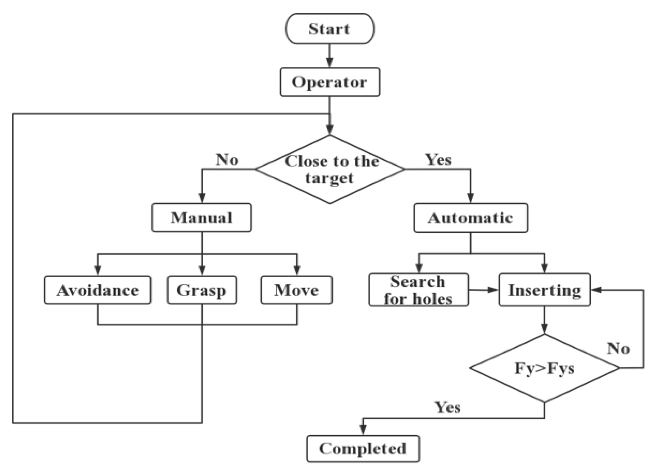
The strategy of manual/automatic mixed control strategy based on Cartesian impedance control is shown in
Figure 3. When the task starts, the motion-tracking device is operated by the operator, and the command position is transmitted to the remote robot or the virtual environment. During the period from the starting point to the target point, the manual operation mode is adopted. The operator controls the remote manipulator to approach the target position flexibly with the assistance of vision and human intelligence. According to the requirement that enables automated hole finding [
31], when the operator observes that more than half of the cross-sectional area of the rod is projected in the hole, the signals for control mode conversion are sent by the operator, and the automatic assembly method is carried out. The robot arm moves gradually toward the current axis direction and realizes hole searching through planar Archimedes spiral search strategy. Then, the remote robot accomplishes automatic and compliant peg-in-hole assembly with the Cartesian impedance control algorithm.
4.3. Integrated Position/Force Control Method Taking the Demonstration Position as the Desired Position
As a compliant control algorithm, the impedance control algorithm shows great performance in automatic control, such as in involved automatic hole finding [
32,
33] and automatic compliance hole assembly [
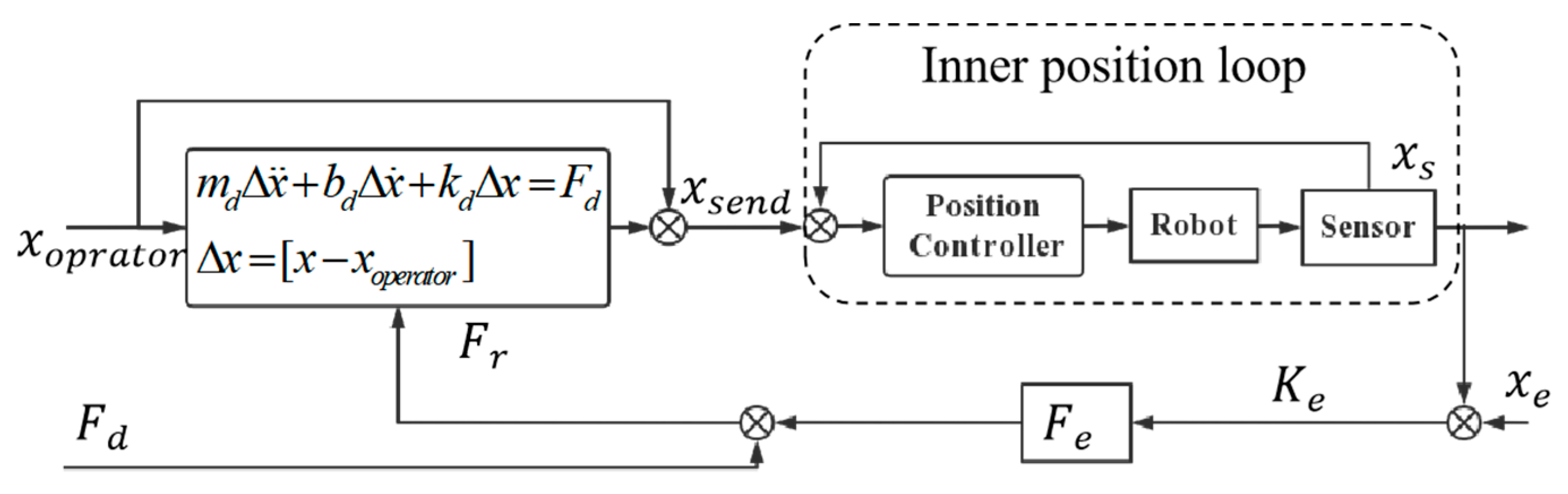
34]. However, the application in combination with teleoperation requires further investigation. In this control strategy, to eliminate hand jitters and achieve accurate assembly by manual teleoperation, we designed an integrated force/position impedance control method in which the operator position was taken as the desired position. Human manipulation was incorporated into the autonomous conductance control loop to combine the human operational initiative and the compliance of impedance control.
Figure 4 shows the structure of this controller.
The position correction controller at the end of the remote robot is a typical impedance controller:
where
,
, and
still represent the virtual inertia, damping, and stiffness of the system, respectively. Unlike the automatic compliant assembly method discussed in
Section 4.2, the desired position in
is no longer a theoretically expected value, but rather the operator’s command position
, which is directly controlled by the operator’s demonstration position; that is:
The output command position of the integrated position/force controller is a combination of the operator movement position and the compliant correction position
where
is the adjusted command position sent to the remote robot.
5. Experimental Validation
5.1. Experimental Setup
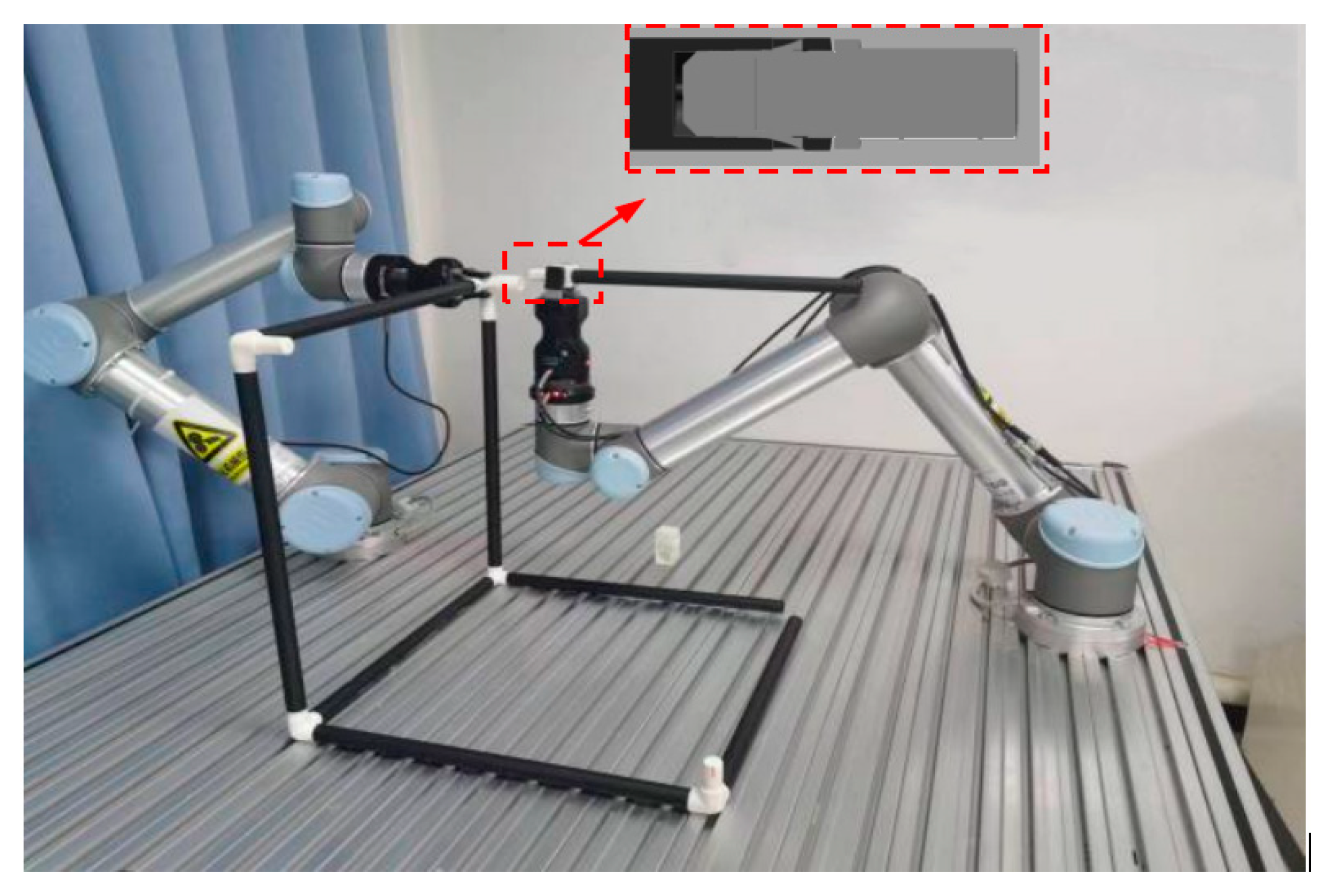
To evaluate the designed control methods, a teleoperation assembly system was constructed at the lab (
Figure 5). The UR5 6-DOF robot was employed as the remote robot equipped with a Hand-E gripper and a force/torque force sensor. A haptic feedback glove developed in our laboratory was adopted to manipulate the gripper. The Intel Realsense D455 camera was applied to acquire the video information about the remote environment. The control algorithms and the interactive command were run through PyCharm. Unlike the commonplace adoption of the ROS (Robot Operation System), the controller of the remote robot was carried out in Python under the Windows 10 system.
For evaluating the effect of the teleoperated assembly system, a typical task called “picking moving, target inserting” was performed. The user controlled the remote robot by operating the wearable wireless tracking device. During the insertion assembly, the end-effector of the robot had to try to minimize contact forces. The assembly components are depicted in
Figure 6. The components were designed with chamfers, and the assembly error is 2.5 mm. The left robot arm was fixed, and only the right robot arm was operated by teleoperation.
5.2. Precision and Effectiveness of Teleoperation System
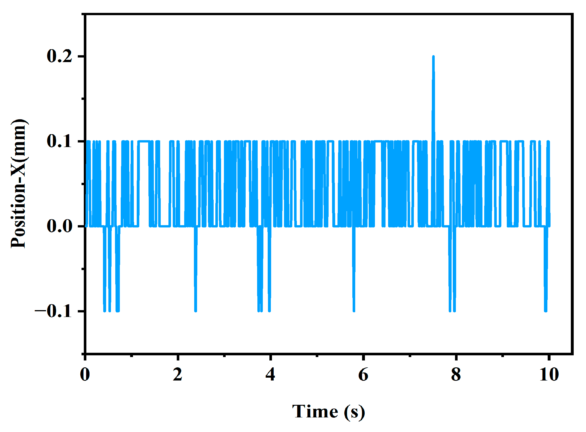
5.2.1. Positioning Accuracy of the Tracker
In the experiment, the lighthouses were posed as described in
Section 3. The positioning sensor (tracker) was mounted on a rigid plate, with the assumption of no wobbling. The 6D coordinate information of the tracker was recorded in real-time. The positioning accuracy was illustrated with the data of the
X-axis, and the results are shown below.
From the tests, it can be seen that the jump of the position signal in the resting state was about 0.2 mm, which is consistent with the results tested in the literature [
35,
36]; the VIVE tracker showed a mean rotational error of 0.13 ± 0.08° and 0.3 ± 0.07°, and a mean translational error of 0.336 mm. The position trailing was precise enough for a teleoperation system.
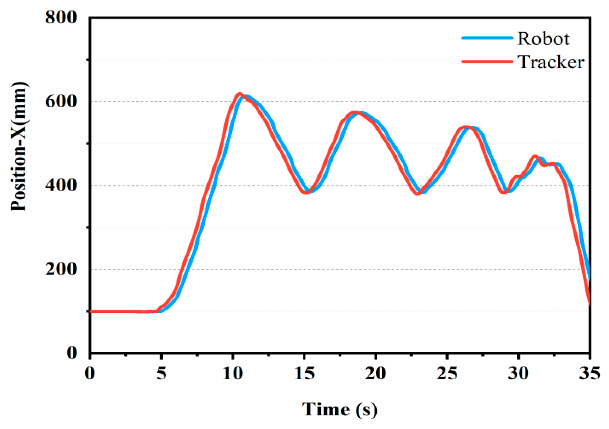
5.2.2. Position Tracking Accuracy
The operator wore the tracker and moved randomly; the remote robot followed the trajectory of the operator. The force and position data were recorded.
Figure 7 describes the tracking performance in the X direction. The red line represents the positions on the local side while the blue line shows the positions on the remote site. At the beginning, the tracker was kept fixed. The results showed that the static tracking error of the robot arm was 0.336 mm, which matched the discussed positioning accuracy of the tracker. When the operator moved randomly, the results demonstrated that the relative position errors were 6.2 mm in motion. The large tracking error in the motion state was caused by the delay in motion response, since the remote robot received a new motion command before it had moved to the target position when some points had not yet arrived. Experiments have shown that the position trailing was precise enough for teleoperation, and the teleoperation system was effective.
5.3. Experimental Results
In our experiments, we evaluated the three different control methods designed in
Section 4. The results are shown below.
5.3.1. Master–Remote Position Controller
In this assembly experiment, the master–remote position control was implemented; the remote robot followed the exact trajectory sent by the operator. The touch force and the trajectory were recorded. As observed in
Figure 8, the biggest contact forces on the measured direction amounted to 11 N—a hazardous force that might cause damage to the robotic system or the assembled components. Tiny position deviations can create large collision forces, and the performance of teleoperation largely depends on the operator’s experience.
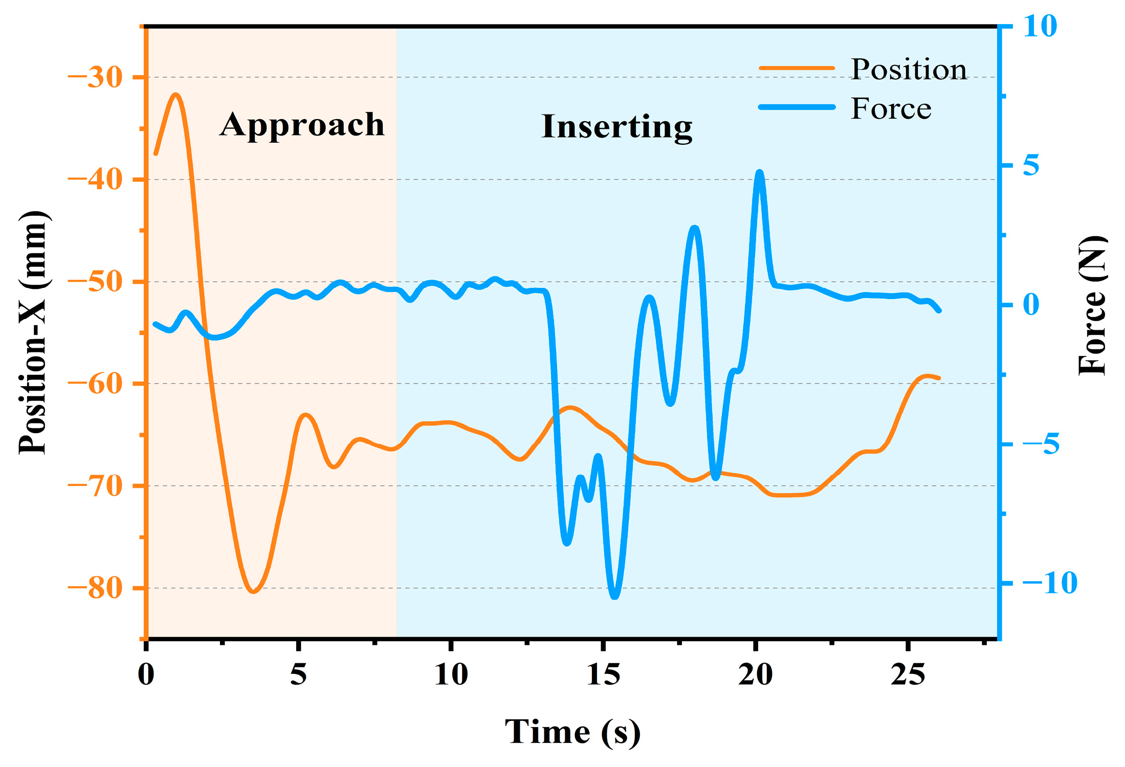
5.3.2. Manual/Automatic Mixed Control Strategy Based on Cartesian Impedance Control
In the mixed manual/automatic strategy based on Cartesian impedance control, the remote robot was guided by the operator once, close to the target point. Then, the robot accomplished automatic and compliant peg-in-hole assembly through the designed Cartesian impedance control algorithm. During the automatic inserting process, the end-position of the robot in the X and Z axis is adjusted through the impedance control. The remote robot gradually inserted the peg into the hole by position control until the contact force in the
Y-axis exceeded the threshold (
). Based on experiments and related studies [
14], in the impedance controller, the impedance parameters were set as
= 1,
4, and
= 0.
The contact forces and position trajectory under the impedance controller are depicted in
Figure 9. From the relationship between the force and the corresponding position in the initial stage of the automatic inserting, it can be derived that, as a force control method, the impedance control is capable of dynamically adjusting the command position according to the contact force that prevents excessive contact forces from occurring. The maximum contact force in the
X-axis declined to approximately 5 N, and there were similar results in the
Z-axis (maximum contact force of about 4 N).
5.3.3. Integrated Position/Force Control Method Taking the Demonstration Position as the Desired Position
Distinguished from the traditional hybrid force/position control, in which the force control and the position control are in two non-interfering directions, the proposed integrated position/force control method took the demonstration position as the desired position. In the same motion direction, the robot executed the combination of operator control commands and local adjustment position commands. The operator’s control commands reflected the user intent, and the local impedance force control loop performed position correction based on external contact forces. This enabled the combination of the operator’s control intent and the impedance correction. In the experiment, the parameters of local impedance force control were still set as
= 1,
4, and
= 0.
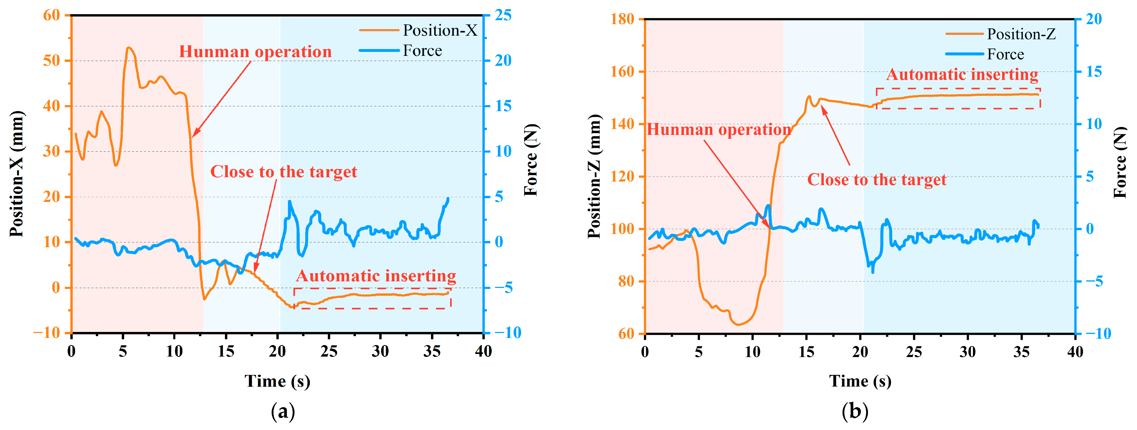
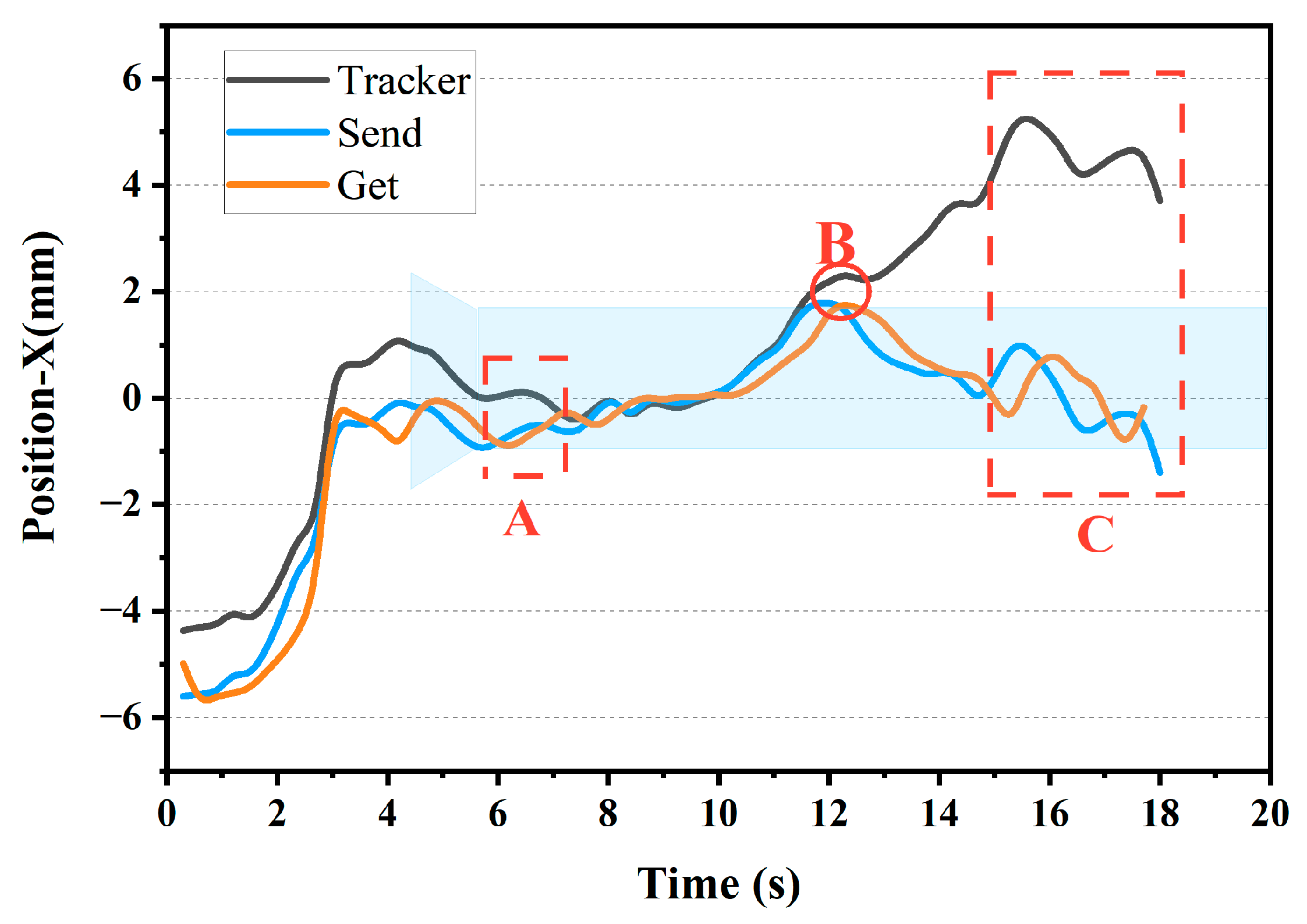
Figure 10 and
Figure 11 show the position and contact force during assembly using the proposed integrated force/position control method.
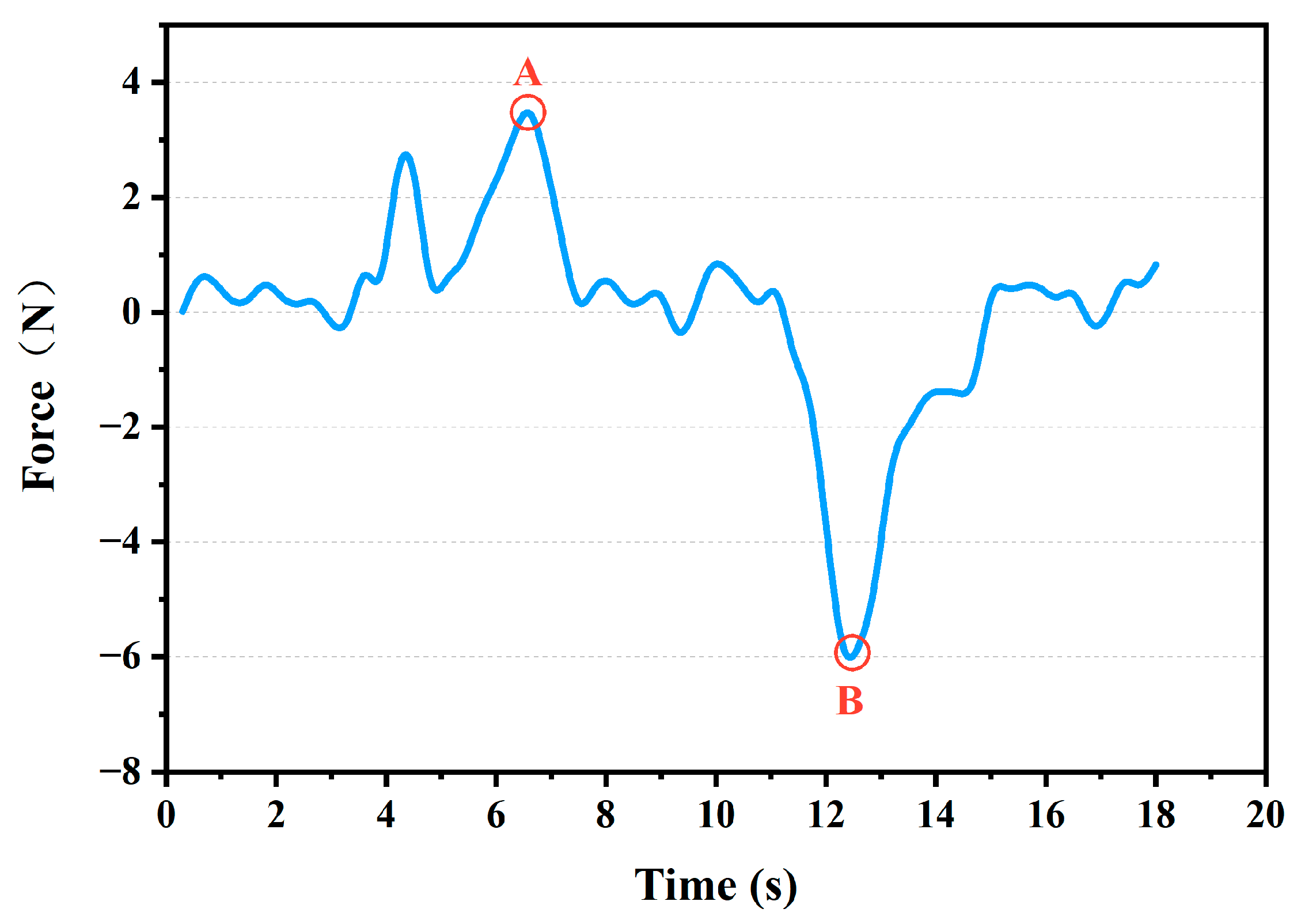
Figure 10 describes the trajectory of the operator (tracker), the desired position, and the actual robot position in the X direction. As shown in
Figure 10, at point A (T = 6 s), the end of the remote robot makes contact with the pipe. At this point, it can be observed that under the impedance adjustment, the corrected command position (blue line) and the actual position (orange line) were retracted to the center of the hole–compared with the operator’s position (black line). It is more evident at point B (T = 12 s) that a strong collision with the circular hole was produced. It can be observed clearly that the operator’s position deviated severely from the center of the circular hole and generated a huge collision force. However, under the adjustment with local integrated impedance-based control, the corrected commanded position and the actual position were pulled back toward the center of the circular hole (value = 0). Furthermore, as shown in area C of
Figure 10, although the operator’s demonstrated position significantly deviated from the hole position, the robot arm was still in the round hole, and no collision was created. By careful observation, it can be seen that the motion trend of the operator remained consistent with that of the commanded position and the actual running position. As can be seen in
Figure 11, the maximum contact force was about 7 N. The contact force was short-lived because the impedance algorithm kept it away from the collision.
5.3.4. Statistical Experiments
A statistical analysis was performed on the results of 10 replicate experiments for each method. In each experiment, the tasks and conditions were the same as described above.
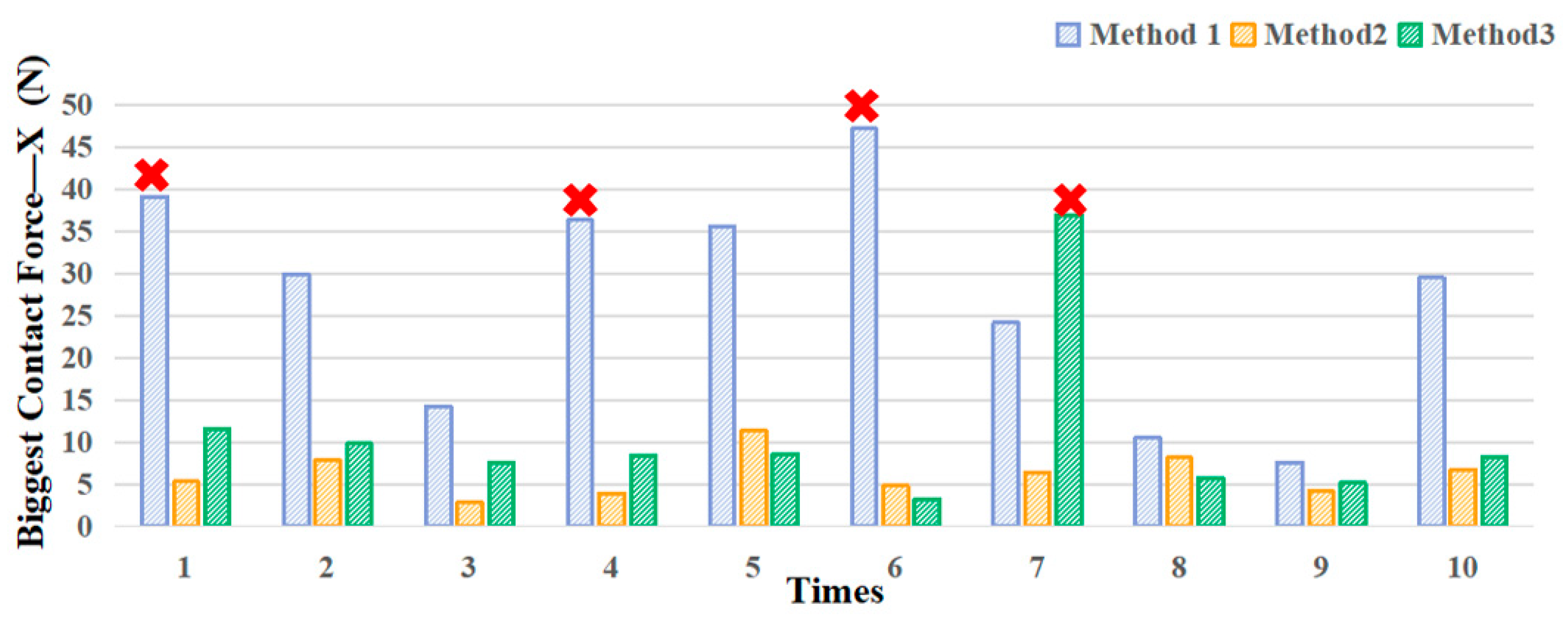
Figure 12 compares the biggest contact force in the X axis during inserting phase of different methods.
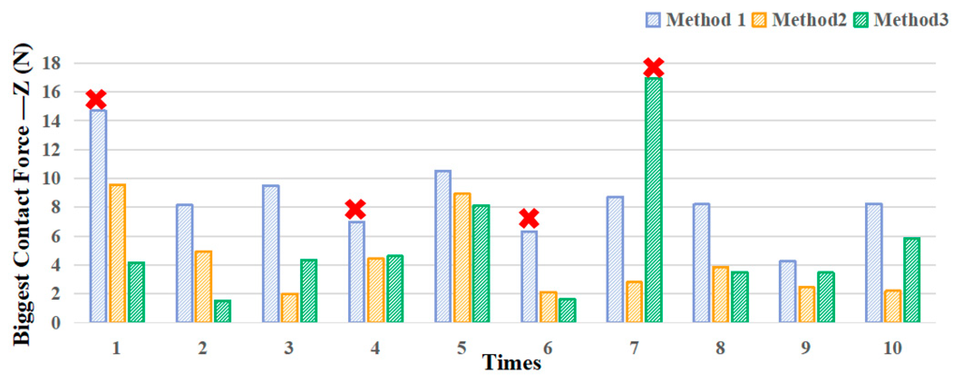
Figure 13 shows the biggest contact force in the Z axis. Additionally, the success rate of task was also counted.
The horizontal axis shows the number of experiments for each method, and the vertical axis shows the maximum contact force of the method in that experiment. Those red “×” indicate that in this experiment, the remote robot stopped for protection due to excessive contact force.
As observed from
Figure 12, owing to the lack of position error correction mechanism, the position control shows the worst performance, with the average biggest contact force in the X axis of about 27.35 N. When implementing the assembly task by the proposed integrated position/force control method, the maximum contact force in the
X-axis declined to approximately 10.49 N, which is less than that of the master–remote position control (decreased by 61%). This means the proposed method possesses the ability of position error correction on human manipulation. The manual/automatic strategy based on impedance control performs the minimal average biggest contact force (about 6.12 N). However, it is only applicable to a specific known environment and needs to be redesigned or even failed when the environment changes [
14]. In addition, method 1 possesses the maximum difference of square of 12.42, which was significantly higher than method 2 (2.37) and method 3 (9.09), indicating that the master–remote position control method was more susceptible to human The data in the
Z-axis have similar results (8.55 N, 4.32 N, 5.4 N), but the force in this direction is small. This is because due to the use of the parallel gripper, when the force is too high, the loaded workpiece might slide in this direction. Additionally, both the automatic assembly and the proposed algorithm possess a similar high success rate (100%, 90%), while in the first, fourth, and sixth position control tests, the remote robot stopped for protection due to excessive contact force.
5.4. A Challenging Task
In order to show the superiority of the proposed integrated position/force control method, a more challenging task was conducted in this section. As shown in
Figure 14, to simulate motion in a complex and unknown environment, a rigid plate with a channel was fixed on the test bench. The channel was complex and irregular, with a distance of 10 mm between the pipe wall and the pipe rod. The robot was asked to move from the starting point A to the end position B while avoiding obstacles.
Impedance control performs well in adjusting the end posture of the manipulator, but it is a fully automatic method, powerless in complex and unknown environments. In a complex motion trajectory such as a curved surface welding task, the desired trajectory needs to be predefined before the pose adjustment by impedance control [
37,
38,
39], or it must adopt the strategy of employing force control in one direction and position control in another direction [
40]. This not only makes the design complex, but it is also not suitable for unknown and changing environments. Therefore, method 2, designed in this work, and conventional impedance control are not qualified for such a challenging mission.
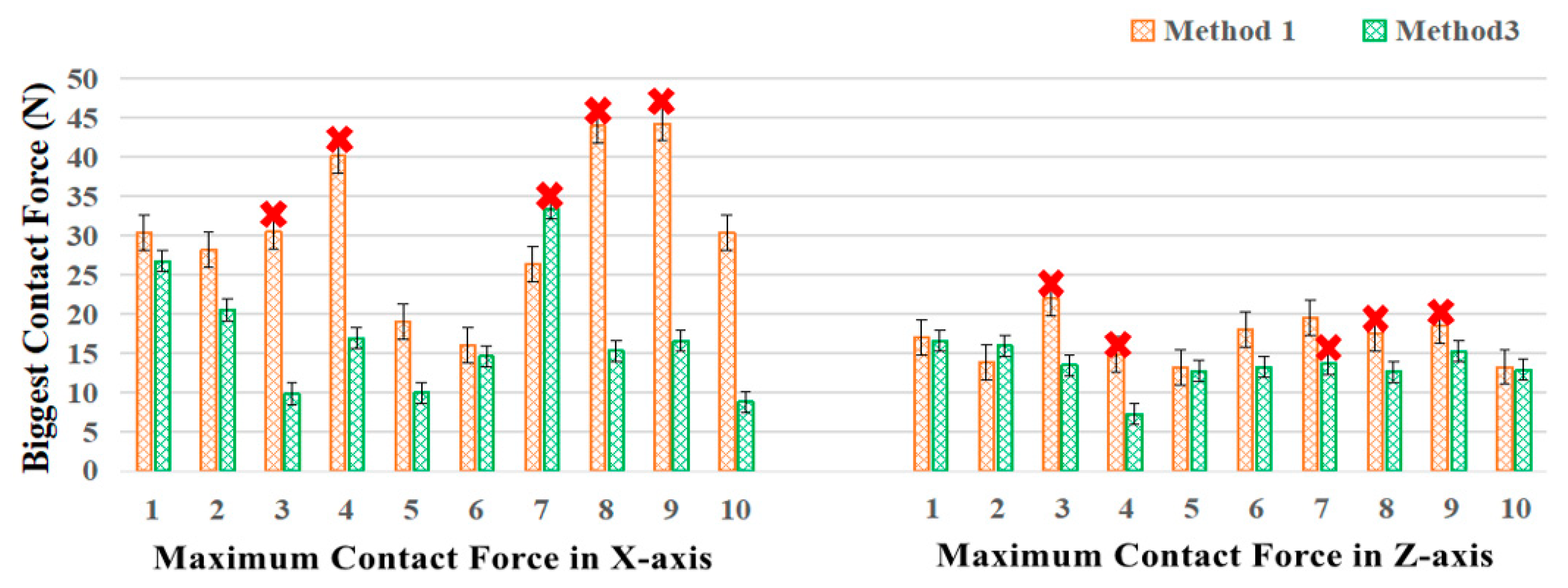
Figure 15 shows the contact forces of the X and Z axes during movement under the position control and the proposed integrated position/force control method. Due to the visual error and hand position error, the traditional position control often leads to task failure for such a complex task, and the task success rate was only 60% with an average maximum contact force of 20 N. In contrast, the method proposed in this paper allows the remote robot to move forward in a complex irregular trajectory under human guidance, and at the same time, it could dynamically adjust its posture according to the contact force, and the task success rate increased to 90%. In addition, it can be seen in
Figure 15 that the integrated position/force control method had a lower collision risk than the method based on position control. There was a similar trend in the Z direction; however, the workpiece might slip due to insufficient clamping force, so the force in this direction is small. The reason for failure is the overshoot of the impedance correction due to excessive collision forces caused by large manual errors.
In summary, it can be seen that the designed integrated position/force control method is able to guide the robot to work in unknown and complex environments. Compared with traditional impedance control, this method possesses higher control initiative; compared with position control, it possesses the property of position correction, which can suppress excessive contact force caused by human misoperation.
6. Discussion
The performance of the three different control methods were verified with representative experiments. In the following, we discussed the proposed integrated position/force control method by the experimental data and related literature.
(1) Compared with the conventional position control (
Section 4.1), which has a good performance in free space, the average maximum contact force during the insertion of the proposed integrated position/force control algorithm decreased from 27.35 N to 10.49 N. The results indicate that, during the teleoperation insertion assembly, the proposed method possessed the capacity to pull back the position of the hand toward the center of the hole to alleviate the rigid collisions caused by position errors. This result has a similar situation in the challenging test. Moreover, the contact force was short-lived because the impedance algorithm kept it away from the collision.
(2) Compared with the manual/automatic mixed control strategy based on Cartesian impedance control, the impedance control-based peg-in-hole assembly shows higher accuracy and lower contact force, and the average maximum contact force decreased from 10.49 N to 6.12 N. However, the disadvantage of the impedance controller is that the method is a fully automatic strategy, and the remote robot cannot be controlled by the operator directly. When the target shape is changed, the impedance controller needs to be re-customized to fit the different situation [
41]. This was further verified in the designed challenging task. In a complex motion trajectory such as a curved surface welding task, it is necessary to predefine the desired path in the process of impedance control. This not only makes the design complex, but it is also not suitable for unknown and changing environments. The proposed method adjusts the position on the basis of human operation. Therefore, the human manipulation was incorporated into the autonomous conductance control loop to combine the human operational initiative and the compliance of impedance control.
(3) Compared with the traditional hybrid force/position control algorithm which divides the motion space into the force control space and position control space, and has certain requirements for the timing of conversion, when the moment to switch control mode mismatches the instant of the actual environment change, unstable responses may be caused [
14]. The proposed integrated position/force control method took the demonstration position as the desired position and, in the same motion direction, the robot executed the combination of operator control commands and local adjustment position commands. There is no process of mode transformation.
In summary, the proposed method has higher accuracy compared with position control and higher flexibility compared with conductance control. Additionally, it achieves the combination of the operator’s initiative and the precision of automatic assembly, and it can alleviate the rigid collisions caused by position errors.
7. Conclusions
This paper presented a teleoperation system which achieves compliance and precise remote assembly with a wearable wireless tracker. In order to eliminate hand jitters and misoperation and to improve operational flexibility, a novel compliance method taking the operator’s position as the desired position was put forward. First, the operator’s movement posture was captured using the wearable tracker. The motion calculation methods were applied to make the positional information accurate. Second, the master–remote position control and the manual/automatic mixed controller based on Cartesian impedance control were implemented as comparisons. Then, a novel integrated position/force control method taking the demonstration position as the desired position was proposed to eliminate position errors caused by hand jitters and misoperation. The results of the experiments indicate that, when compared with the master–remote position control method, the proposed method possesses the capacity to pull back the position of the hand with errors toward the center of the circular hole. Moreover, compared with the automatic impedance control assembly, the proposed control scheme provides greater control flexibility and successfully combines the operator’s initiative and the compliance of impedance control assembly.
However, this method also has some disadvantages: for example, when the contact occurred, the combination of human adjustment and the correction of the impedance control may lead to over-correction, causing secondary collisions. When the assembly error is small, the weight of the human operation should be limited. In a future study, we would like to use the machine learning approach to adjust the weights of impedance control and human operation in different cases. In addition, differently shaped assembly tasks should be studied in future studies to test the feasibility of our system across different components and environments. Furthermore, the impedance correction controller needs to be further optimized, such as through investigating the dynamic adjustment of impedance parameters to accommodate assembly in different environments.


