Article

CAD-Based Feature Recognition for Process Monitoring Planning in Assembly

Institute for Machine Tools and Industrial Management (iwb), Technical University of Munich, Boltzmannstr. 15, 85748 Garching, Germany
*
Author to whom correspondence should be addressed.
Appl. Sci. 2023, 13(2), 990; https://doi.org/10.3390/app13020990
Submission received: 6 December 2022 / Revised: 31 December 2022 / Accepted: 3 January 2023 / Published: 11 January 2023
(This article belongs to the Topic Modern Technologies and Manufacturing Systems, 2nd Volume)

Abstract

:
Process understanding and process monitoring are of great importance in production in order to control processes and guarantee a high quality. Demanding customer requirements with an increasing number of variants pose an even greater challenge to the quality of the processes, as this must be maintained at the highest level even in the event of process changes. In addition, new regulations and standards require process data to be recorded and stored, especially in manufacturing environments for medical and safety equipment (e.g., surgical instruments, camera systems in the automotive industry). Continuous variations in production processes and changes to products and the production system mean that the planning effort required to implement process monitoring has become vast. This is where automated planning and decision support systems become important. They are able to manage the complexity arising from alternative solutions and present suitable alternatives to the user. This article deals with the computer-aided identification of assembly features, which influence process monitoring and the generation of production system-neutral tasks for process monitoring. Computer-aided feature recognition methods were used to derive features from three-dimensional models. Furthermore, a skill-based approach was used to formulate tasks for process monitoring. This publication thus aims at the automated and product-specific generation of processes for process monitoring.

1. Introduction

In recent years, industrial production has increasingly demanded customized and high-quality products. Therefore, flexible and reconfigurable production systems (i.e., flexible and reconfigurable manufacturing systems (FMS and RMS)) are emerging to meet customer requirements while maintaining high quality standards. In addition to increasing customer demands for high product quality, stricter regulations and standards mean that companies have to control their processes better [1,2]. In particular, safety standards and regulations have become stricter in the production of electronic components with a high safety relevance and medical devices (e.g., due to the MDR - Medical Device Regulation (MDR) 2017/745) [3]. In addition, the increasing awareness of sustainable production and the avoidance of waste (i.e., material and resources) requires an increased reproducibility of the production processes. To meet these requirements, process data need to be recorded and analyzed. Assembly is one of the most important phases of manufacturing, accounting for a significant portion of the total production time and total manufacturing costs [4]. A large proportion of the costs are incurred in assembly, where faulty production processes cause high costs. Assembly involves upstream value-adding processes, so defects are particularly noticeable here. Quality control or inspection only after the assembly process is time-consuming and cost-intensive. Additional inspection processes have to be designed, which cost time and add no value to the product. To improve the assembly quality and reduce the overall assembly time and cost, an efficient approach to monitoring the assembly process is essential. Process monitoring has been studied as a possible approach for quality control [5]. More flexible and reconfigurable production systems can adapt an existing production configuration for the assembly of a new product variant while also integrating sensors for process monitoring. Unfortunately, this often requires a great deal of manual effort and expert knowledge to identify the resources and sensors capable of monitoring the processes directly (e.g., monitoring a joining process with a force–torque sensor) or indirectly (e.g., monitoring a joining process with sensors integrated into the robot axes). Different assembly processes and ways to assemble a product also influence the ability to monitor these processes. Determining monitoring requirements is the first step in process monitoring planning in assembly and is dependent on product, process, and resource information. To reduce the manual effort and expert knowledge required, automation approaches are needed to manage this complexity. This paper presents an approach that addresses precisely this issue (i.e., a reduction in effort and required expert knowledge) through the automated identification of monitoring requirements. It is structured as follows: after the introduction in Section 1, a literature review on process monitoring and inspection planning is given in Section 2. This section analyzes the literature to show the need for action regarding why the automatic generation of process monitoring requirements with feature recognition is relevant. Computer-aided approaches in process and inspection planning are also considered to identify the benefits that can be applied to process monitoring planning. Finally, product and process features (i.e., geometric and process-specific) and feature-based approaches required for process planning are described. Section 3 gives an overview of the overall system developed and then goes into detail about the individual modules (e.g., feature extraction and feature recognition) for generating monitoring requirements. The results are presented in Section 4, leading to a discussion of the system and results in Section 5. Finally, Section 6 summarizes the publication and presents an outlook for future research.

2. Literature Review

This section provides an insight into process monitoring in general and shows approaches in the field of computer-aided process planning (CAPP) and inspection planning (CAIP). Furthermore, features and feature-based approaches relevant to process and inspection planning are presented.

2.1. Process Monitoring as Part of Inspection Planning

According to DIN 9000:2015 [6], quality control is part of quality management. Here, the focus is on achieving quality, which is defined as “[the] degree to which a set of inherent characteristics of an object [meets] requirements” [6]. To determine the quality of products, quantitative and qualitative characteristics, called inspection characteristics, must be determined [6]. Quality control is defined by variables that affect processes and lead to changes in product characteristics. These variables need to be monitored to diagnose the state of the machine and process [7,8]. Various quality control strategies exist for assembly, such as process monitoring at several stations, the monitoring of individual processes (e.g., during joining), and product quality testing [1,6]. Depending on the scenario resulting from the availability of sensor data and the complexity of production, some strategies are more favorable than others. Process monitoring as efficient runtime data acquisition and information provision, as well as data analysis and the recognition of patterns in quality-relevant process data, leads to increasingly better insights into the production process and its internal and external influences [1,9,10]. Direct and indirect process monitoring methods can be used to directly or indirectly monitor the relevant quality characteristics [5]. As an example, a force–torque sensor of a robot serves as a direct monitoring method for detecting the accuracy of a joining process. The evaluation of the sensors in the individual axes of the robot based on current deviations is an indirect monitoring approach. Direct monitoring methods have a higher accuracy because the sensor and sensor data are specifically designed to monitor the process. Indirect monitoring methods, on the other hand, can be more cost-effective and industrially applicable by using existing sensor data and correlating them with process quality [5,11]. The increasing complexity of planning is based on a large number of possible process alternatives and factors that have to be taken into account due to the various possibilities of reconfigurable production systems. Greater variations in process parameters and technologies, as well as different alternatives, lead to an increased complexity not only in monitoring planning but also in process and assembly planning in general. Decision support systems can facilitate the planning phase by suggesting suitable alternatives according to predefined criteria (e.g., a high required accuracy or a low number of required reconfigurations) [12,13,14,15]. However, before decision support systems can be used for planning, the data required for process monitoring planning are needed. In this case, quality requirements need to be identified that can later be monitored with appropriate resources (i.e., sensors). An overall decision support system capable of matching requirements with the monitoring skills of an existing production system and its resources was presented in previous works [15,16,17]. The aim of our work is to determine the quality requirements necessary for process monitoring semi-automatically. This provides a decision support system for the user, who is still able to interact with the system. The motivation for this work lies in the consideration that a new product variant with its existing assembly sequence and assembly plan can be analyzed with a reduced manual effort and lower required expert knowledge to determine the quality requirements, making the planning of process monitoring for small batch production more efficient. Multi-variant production on a flexible/reconfigurable production system requires multiple iterations of process planning. The approach in this work was therefore to identify monitoring requirements as part of the inspection planning. In the process planning phase, this can be classified as a subsequent phase of process or assembly planning [18].

2.2. Computer-Aided Process Planning and Inspection Planning

The flexible assembly of products on a given production system leads to high complexity in the planning processes. For example, the identification of processes, assembly sequences, the allocation of resources to individual processes, and the multiple use of the production system (e.g., unidirectional and bidirectional material flow) are advantageous for process planning since a product can be assembled under different bounding conditions (e.g., the capacity of individual production stations or resources) in different ways. CAPP reduces manual effort and the required expert knowledge by automating planning steps [19]. Different computer-aided approaches can be used for individual domains [19,20]. For example, the design of products can be supported by computer-aided design (CAD) tools, and the planning of manufacturing processes by computer-aided manufacturing (CAM) tools. In the area of quality management, CAIP tools can be used to determine the quality characteristics to be measured and inspected. The matching of inspection characteristics with the appropriate measuring equipment can also be performed automatically. Virtual analysis of the part to be manufactured can identify inspection characteristics and measuring equipment. These tools primarily focus on manufacturing processes and manufacturing characteristics rather than assembly characteristics or processes [21]. The choice of measuring equipment is also often determined in advance and set as a coordinate measuring machine (CMM).

2.3. Features in Process Planning

Several approaches used to improve the efficiency of decision support systems for process planning use features, both in manufacturing and assembly [22,23,24]. Features can be extracted from CAD models and describe assembly knowledge for planning processes. Product features are divided into low-level features (shape features) and high-level features (application-specific features, e.g., assembly features such as joining surfaces) [25]. Low-level features describe geometric and topological units of parts and shapes such as holes, chamfers, notches, and slots. High-level features describe application-specific features in terms of functionality and use. An assembly feature, as a high-level feature, can be the connection between two shape features of different parts in an assembly group. Different definitions of high-level or assembly features can be found [21,26,27]. These definitions differ in depth and application. In general, a high-level feature is significant to the process. In assembly applications, this can be specified by describing the geometric, topological, and process parameters. The study in [27] describes joining features as representing the entities involved in the connection, the joining method, constraints, and geometric shapes (e.g., groove, chamfer). Features of the joining path, tolerances, and gripping positions also belong to this category [20]. In this paper, assembly features relevant to process monitoring are defined as assembly knowledge. Thus, geometric, topological, functional, and process-relevant features are included in this category.

2.4. CAD Feature Recognition

Different feature recognition approaches have been developed in the past few decades to support engineers during the design and manufacturing planning phases [28,29]. In particular, in CAD and CAM tools, these approaches are used to improve the identification of features for manufacturing processes (e.g., inspection criteria for milling processes), as can be seen in Table 1. Most of the approaches rely on an analysis of the CAD model of the product as a bounding representation (B-Rep). In B-Rep models, volumes are described internally by the surfaces bounding them and, thus, by the boundary edges. In addition to the standard analytical curves and surfaces (cylinders, planes, circles, ellipses), free-form surfaces and curves are also used. The direction of the normal vector of the surface pointing toward the material is used to uniquely define on which side of the surface the enclosed volume is located. Based on the representation of individual parts, different approaches have been developed to identify form and geometrical features in CAD models [28,29]. Table 1 below shows some approaches for feature recognition. Depending on the objective and focus, the approaches vary for specific use cases (e.g., critical milling features). The column “focus” shows the main characteristics of each approach and describes the best fit of each approach. As can be derived from the table, a hint-based approach has been proven to be especially applicable for machining features from 2D orthographic projections. Up to a certain point, all approaches presented in Table 1 rely on a rule-based approach. Nevertheless, the rule-based approach is often described in isolation, as the focus is on logical rules rather than volumetric decomposition or hint-based methods.
CAD feature recognition relies on the extraction of data. The data extraction can also be seen as a pre-process for feature recognition. Hereby, external and internal approaches for the extraction of features can be distinguished [24,25]. Internal approaches are included in commercial CAD systems and can be addressed via application programming interfaces (APIs). These approaches extract geometric data and recognize features directly from the corresponding CAD systems. External approaches are independent of CAD systems and use neutral data formats, such as STEP and XML files. Currently, almost every CAD system supports neutral data formats, including the import and export of neutral format files. This promotes the development of a computer-aided approach for the automated identification of features. An external approach is very appealing, especially in the area of assembly features relevant for process planning, where CAD files are often transferred between different commercial tools.

2.5. Need for Action
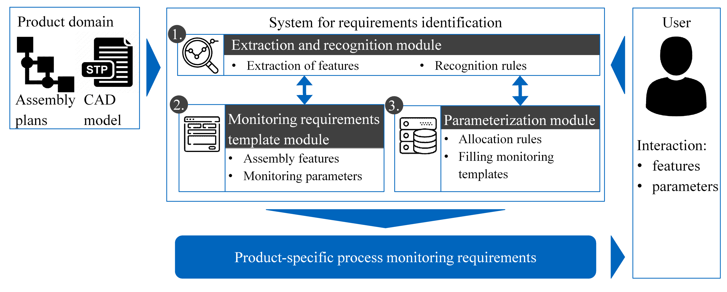
Due to the high manual effort required for the identification and definition of assembly features relevant to process monitoring, as well as the high level of expert knowledge, computer-aided feature recognition approaches are needed. As can be seen in Section 2.4, several feature recognition approaches exist for manufacturing processes (e.g., milling) and process planning (e.g., in combination with CAPP; see Section 2.2). Feature recognition methods have also become a focus of attention in the context of inspection planning for manufacturing processes. Assembly planning uses assembly feature recognition to identify assembly processes and assembly sequences in CAD models (see Section 2.3). There are no approaches yet in assembly feature recognition relevant to process monitoring planning. As can be seen from the literature review in Section 2.4, rule-based approaches seem to be promising due to their individual applicability. Rules must be formulated and applied for this purpose. This paper resolves the lack of feature recognition for identifying monitoring requirements in assembly processes by presenting a system for formulating and integrating rule-based feature recognition that can be combined with predefined templates for monitoring requirements. Different assembly plans and assembly processes lead to a variety of possible monitoring requirements and, with the assigned sensors, to process monitoring plans. An automated approach is therefore required to automatically generate different monitoring requirements. This has the further advantage of the monitoring requirements with the allocated sensors being able to be used as criteria for the selection of an assembly plan [15]. The concept for the automated identification and parameterization of process monitoring requirements with its individual modules is presented in Section 3.

3. Concept

The following section describes an approach for the automatic identification of process monitoring features in assembled products. As can be seen in Figure 1, a user interaction enables the customization of the identification of the monitoring features and parameters and, thus, the individual monitoring requirements of a new product variant to be assembled.
The initial situation for the use of the system or the identification of the monitoring requirements is based on the newly planned assembly of a new product variant with high quality demands. In this case, the product and its assembly plan(s), with its production locations (e.g., stations or cells) and operating resources (e.g., robots and grippers), are defined. Multiple assembly plans and assembly sequences can influence the determination of monitoring requirements. Based on the sequence of components to be assembled, different characteristics may form as a result that are necessary for monitoring. This concept considers multiple assembly plans and creates the monitoring requirement individually for the assembly plans (see Figure 1). Different assembly plans and monitoring requirements can have an influence on the generation of monitoring tasks and plans [15]. Therefore, the main objective for using the following system is to identify and define monitoring requirements that must be considered when planning process monitoring. The product information derived from the CAD model of the assembled product and the information from the assembly plan serve as an input for the system to identify the monitoring requirements for assembly processes. The extraction and recognition of the geometric and process-specific features rely heavily on two sub-modules. The sub-module containing templates for monitoring requirements describes known geometric features and process parameter types that are relevant to the successful execution of the assembly processes. These templates must be created manually in advance. The templates are based on existing descriptions (e.g., norms and standards, such as DIN 8593 – “Manufacturing Processes Joining”) of assembly processes and their relevant characteristics. A more detailed description of the templates can be found in Section 3.2. Depending on the complexity of the process and the company’s internal adjustments or additional requirements, the manual setup of a template varies in the time required. These can then be used more frequently for different product alternatives. This recording can be performed in workshops and by experts (e.g., the quality manager or product designer).
The sub-module for parameterizing the process monitoring requirements assigns the monitoring parameters obtained from the assembly plan information, standard process parameters (e.g., the torque of the screw, the joining force), and user inputs. The extraction and recognition module is the core element of requirement identification and serves as a feature extractor for the product CAD model and for feature recognition. First, the CAD data are extracted. This information is then used for feature recognition to determine and identify the application-specific assembly features. Figure 2 describes the interactions between the individual modules and the user. The generation of process monitoring requirements for a single product can be divided into four phases: 1. the import phase; 2. the feature extraction phase; 3. the feature detection phase; 4. the parameter determination phase. The individual phases and modules are described in the following sections. At the end of the cycle, the user can manually define further monitoring requirements that the system does not recognize or that need to be detailed further.

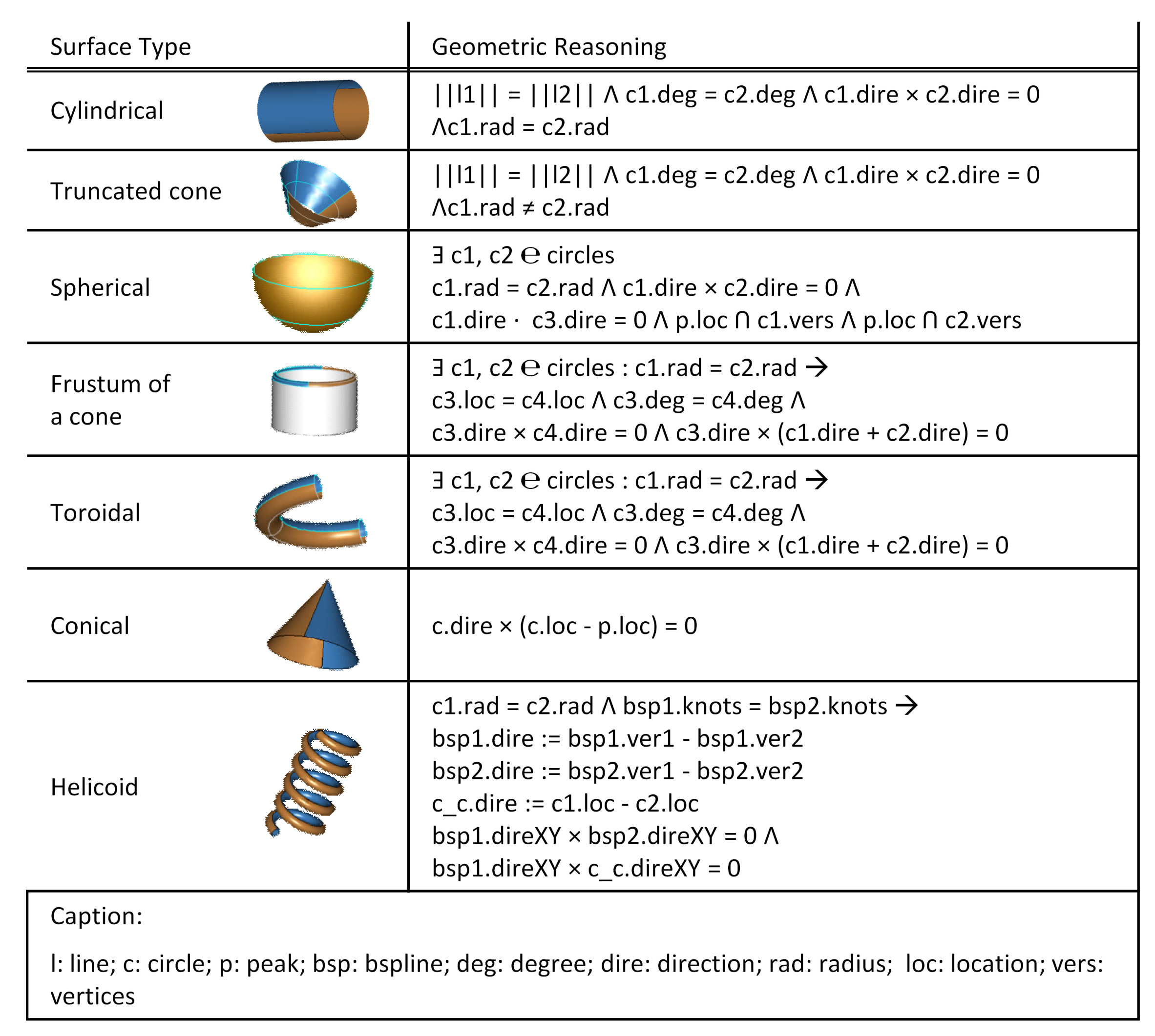
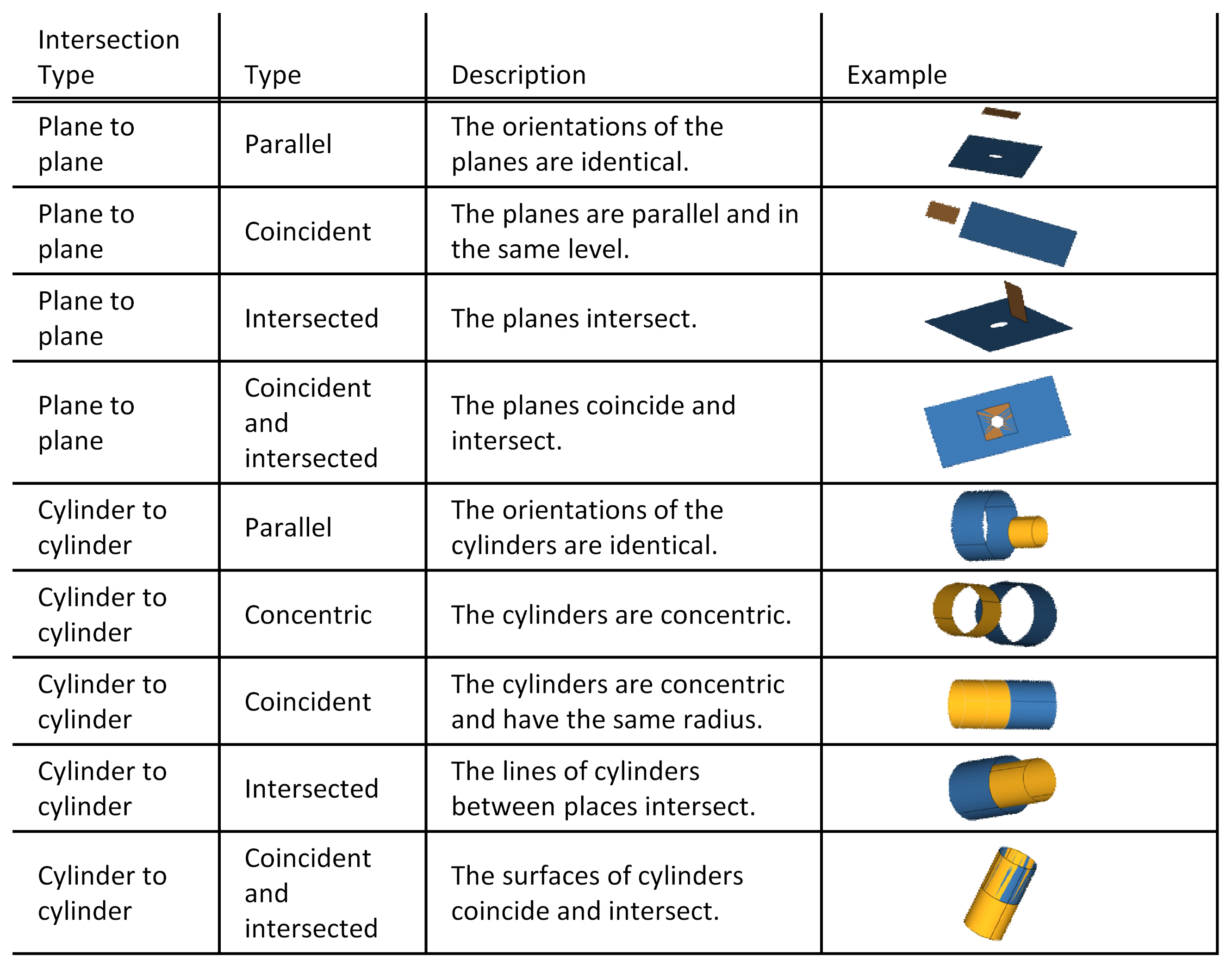
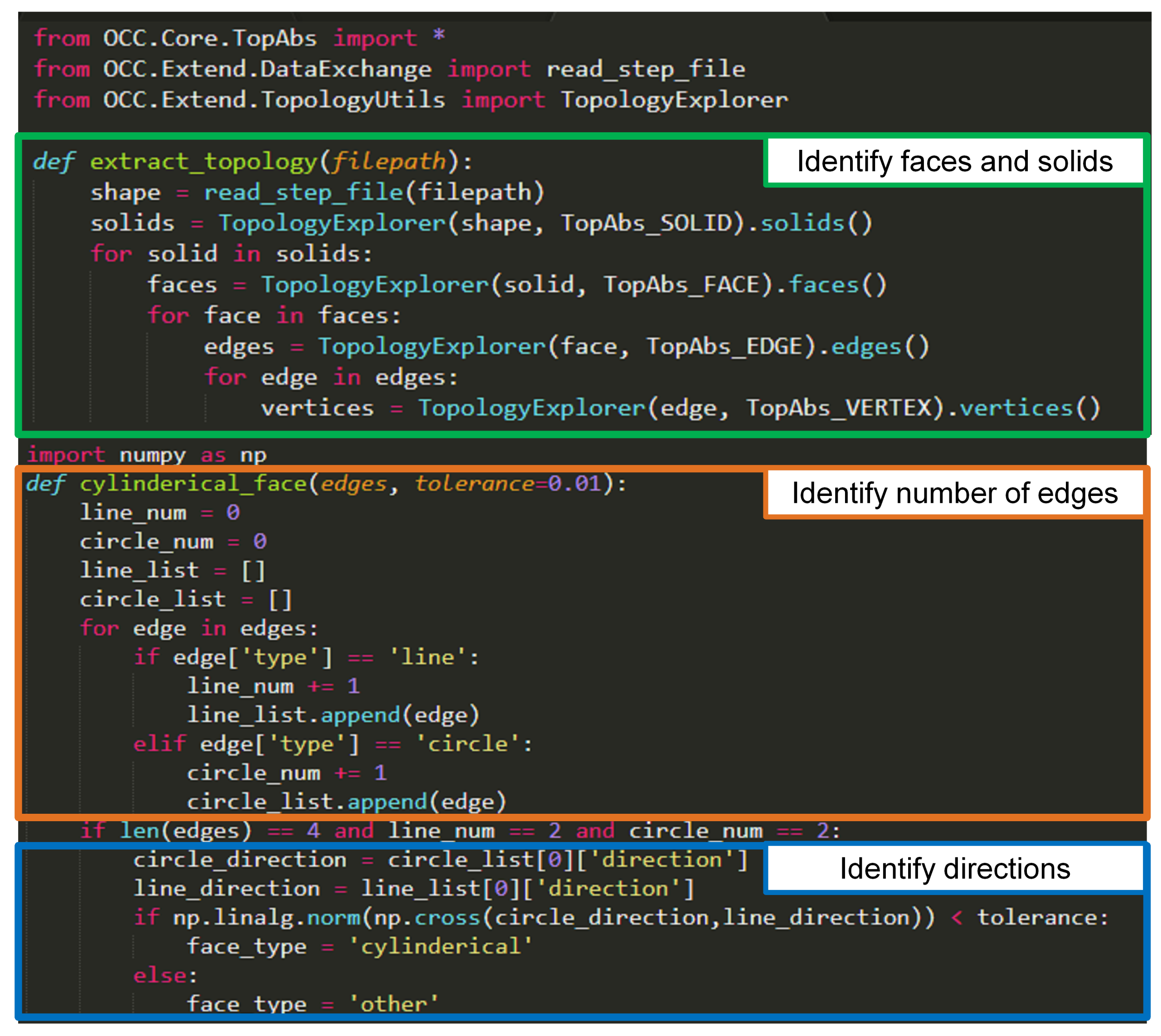
3.1. CAD Feature Extraction and Recognition for Monitoring Processes

The feature extraction and recognition module relies on the information previously imported via the input/output module (I/O module). Here, the process plan (as JSON file) with its individual assembly processes must be imported together with the CAD model of the product (as a STEP file). The process plans consist of the individual required assembly steps and additional process information (e.g., required joining force). This file can be created manually or automatically in advance and shows the individual work plans as the sequence of parts to be assembled. The CAD model as the STEP file contains information about the individual parts, positions, and alignments, and thus the entire assembled product. The extraction step involves obtaining geometrical and topological CAD information from the STEP file for feature recognition. For the extraction of the relevant information, an external approach based on OpenCascade Technology (OCC Technology, https://www.opencascade.com/) was used in this work. Since the STEP format is set up as a text-based file format, the geometric and topological information relevant for feature recognition can be extracted automatically. Various topological entities, such as edges and vertices, are retrieved from the STEP file. The identification of each feature is part of the recognition process. Surfaces, shapes, solids, and connections are recognized (Figure 3). The subsequent recognition of the individual features (e.g., faces) is thus based on the extracted information from the OpenCascade Technology.
Face feature recognition is performed by geometric inference (i.e., application to vertices and edges), resulting in the recognition of cylindrical, circular (conical), and spherical faces. Shape features are recognized by geometric reasoning from surface features and describe holes, hexagons, and m-t shapes, among others. A form feature, such as a hole, can be described as a cylindrical face feature with an inward orientation. An m-t-shape can be described as a cylindrical face that has one or more continuously connected faces whose axis directions are parallel to the axis direction of the cylindrical face (form feature as part of the screw, in Figure 3). Solid features are generated using form features (i.e., face features). These consist of a unique identifier, a transformation (Cartesian coordinate system), the individual planes, cylinders, cones, hexagons, spheres, component information, and, when recognized, standard components (e.g., bolt, nut). For example, a nut can be recognized if a solid feature has only one hole, one hexagon feature, and only one m-t-shape, and their axis directions are parallel to each other. Connection features refer to the intersections between different solids, which are understood as a set of intersections between the faces of different solids (also called Face2Face features). For example, if two cylindrical surfaces have parallel directions and the vector between their centers is parallel to that direction, then the cylindrical surfaces are concentric (see Appendix C). In addition to the information derived from the process plans, further information can be added to these connection features (e.g., a screw connection feature).
As can be seen in Figure 3, multiple features at different levels of different parts merge into high-level features; for example, connection features between parts, such as the congruence of screws and holes or surface contacts between blocks. Combining different features at different levels is part of a rule-based approach based on geometric reasoning. Faces, forms, solids, and connections can be identified by applying geometrical rules (initially to vertices and edges from the STEP file). These features are relevant to assembly and therefore applicable and useful for process planning (i.e., high-level assembly features). Since these characteristics are relevant for process planning, monitoring planning is also included in the utilization of these features. To further enrich these features into monitoring requirements, the next step is to design product-neutral templates for process monitoring requirements and populate them with the recognized features.

3.2. Product-Neutral Process Monitoring Requirements Templates

The templates for monitoring requirements contain empty shells of parameters to be monitored during the process (Table 2). Assembly processes can include up to two parts or groups of parts at once, depending on the process type. While joining processes involve an existing part or group of parts in which the new part is assembled, welding processes do not involve an additional second part or group of parts because a joining process was previously performed. The information about the parts involved in the process to be monitored can be stored in the template and may be relevant when using the monitoring requirements for planning. The template contains names for the two parts or groups of parts as well as their unique IDs in the CAD file. In addition, individual parameter names, units, and types are inserted, which can be derived from process-relevant parameter descriptions (e.g., VDI guidelines, papers, and DIN norms, such as DIN 8593). These parameters can then be filled with assembly features that need to be monitored. These features can be differentiated into geometric and process-relevant features (see Section 2.3). Each feature has a description (e.g., name and ID), a feature type (geometric or process-relevant), a value range (e.g., torque 2.0 Nm to 2.2 Nm), and a volume range (e.g., positions and alignments). These empty shells serve as a template for the parameterization sub-module and are filled with information from the recognition sub-module and process plan information (see Figure 1). The template and its structure are designed according to the monitoring skills of the sensors. This allows for an automatic assignment of sensors to monitoring requirements in further planning steps, which is not part of this article (see Section 2.1) [13,14,16].

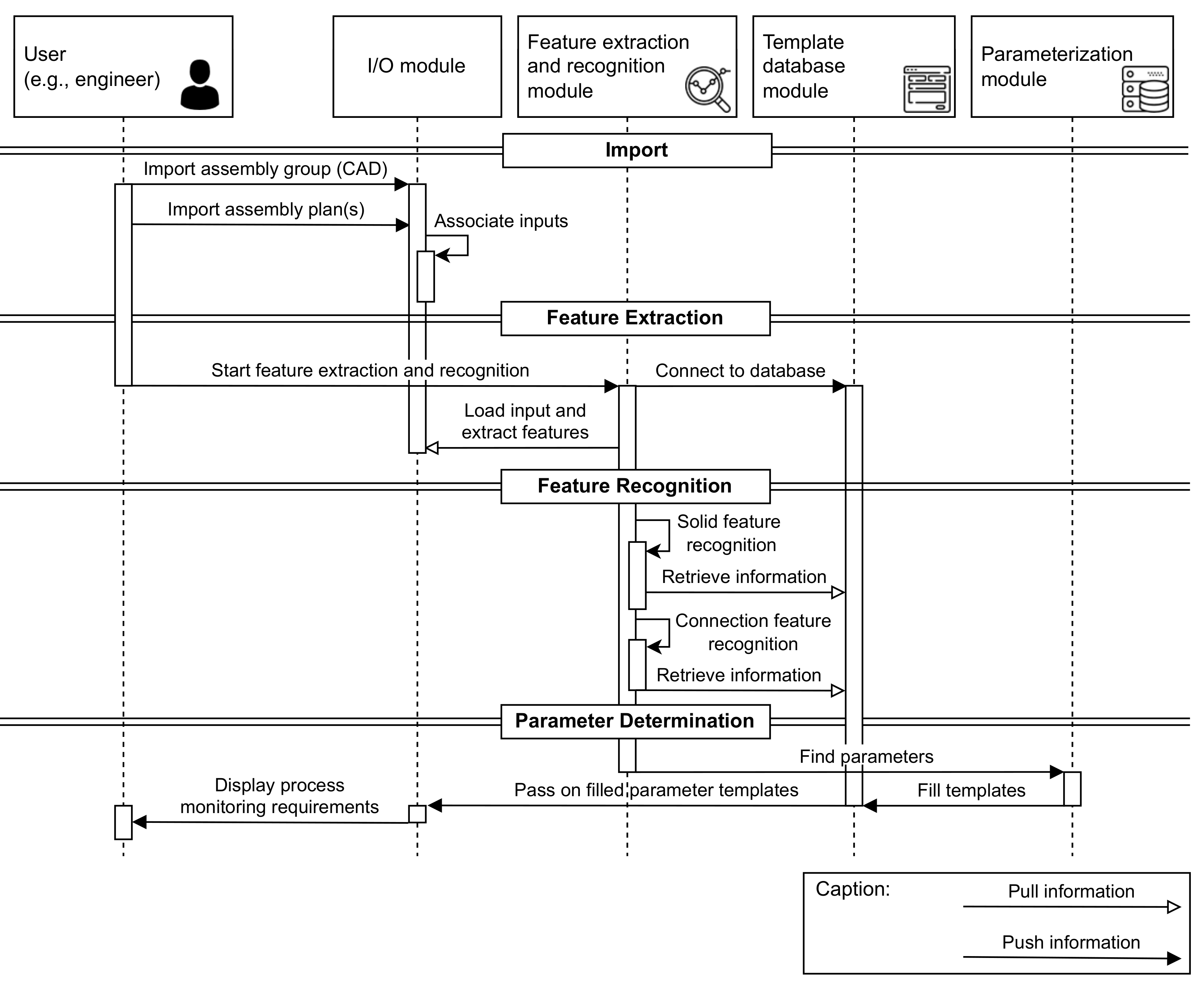
3.3. Generation of Product-Specific Monitoring Requirements
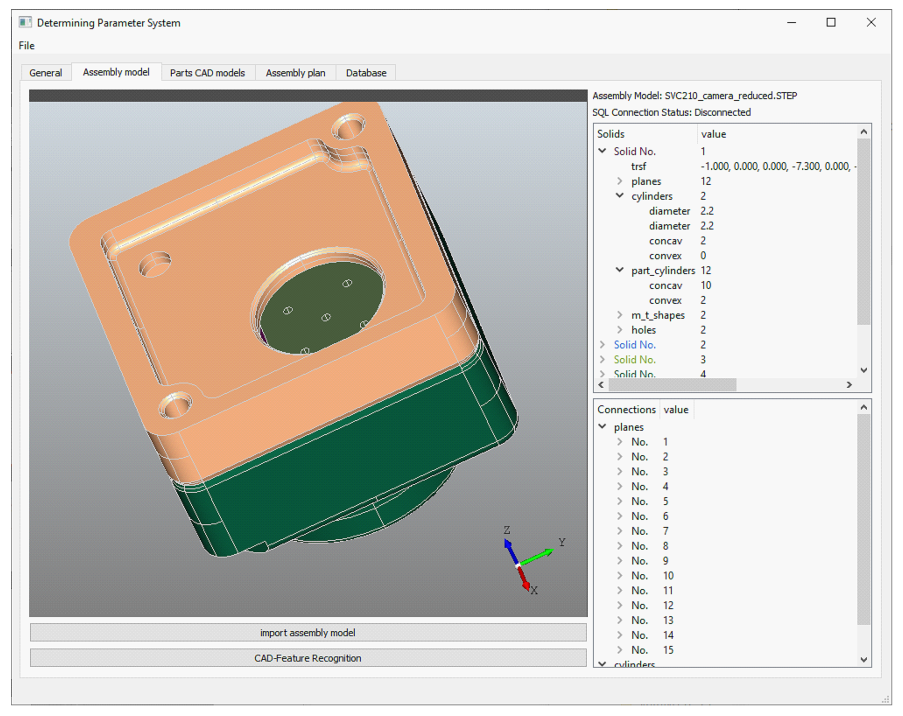
The parameterization sub-module generates the requirements for process monitoring. Information from the recognition module and from the process plan is transferred to the monitoring templates to define the requirements. Allocation rules allow the templates to be filled with information about the part IDs, process types, and feature IDs. For this step, it is important for the process plan to contain information about the processes to be executed according to each part and part ID. The result of this step is a generated list of requirements for each process step of the preloaded process plan. This list can now be manually completed by the user to add additional features that were either not identified in the CAD file or defined in the process plan (e.g., the required torque for the screw and torque to be monitored).

4. Results

The software and hardware used for the implementation are listed in Table A1 in Appendix A. Since OpenCascade provides a Python library (PyOCC) for feature extraction from STEP files, the core element of the approach (feature extraction and recognition) was implemented in Python. The database for the monitoring templates was implemented in an SQL database that interacts with the Python implementation. Each monitoring requirement template for each process type was set up as a database table, as shown in Table 2. To be able to interact with the solution, the visualization was realized in PyQT (see Figure 4). The assembly of an exemplary surround view camera serves as a use case for the implementation. The product consists of two housing parts (lower and upper housing), an electrical circuit board, and four screws (see Figure 5). Two joining processes are required for the electrical circuit board and the two housing parts, four screwing processes to attach the board to the lower housing part, and one welding process to fuse the upper and lower housing parts. Each of these processes requires a different set of process parameters (e.g., joining force, welding temperature).
The graphical user interface (GUI) enables the import of individual files (e.g., process plans, CAD models) and establishes a connection to the template database via a user login (see operation panel 1 in Figure 4). Operation panel 2 then allows the feature recognition and parameterization to be performed. The individual results are then saved in the feature window (recognized features), database window (monitoring templates), and parameter window (process parameters). A logging output displays the current steps and serves as a log file. At the end, the user can manipulate the monitoring requirements in the parameter area:
  • Add monitoring requirements;
  • Delete monitoring requirements;
  • Modify monitoring requirements.
The results are stored in a text-based and human-readable JSON file for further processing (e.g., resource allocation for monitoring planning). As can be seen in Figure 5, the process features from the process plans (JSON file) and the geometric features from the CAD model (STEP file) result in a variety of different monitoring requirements. The assembly sequence shown in Figure 5 is imported via the GUI as a JSON file. The information stored in the JSON file consists of the different assembly sequences, process types (e.g., screwing, joining, welding), and additional process parameters relevant for monitoring (e.g., joining force of 4 Nm). For validation, a surround-view camera and its integration into the software tool was tested (Figure 5). This camera system is used for autonomous driving. Therefore, the assembly processes must achieve a high quality.
The identified features from the process plan and the CAD file are automatically recognized and fill the monitoring templates. Company-internal knowledge can be identified and stored in the templates before the automated approach automatically identifies the requirements using the expert knowledge already available. The template database can be manipulated by the user before applying the monitoring requirement identification.
The monitoring requirements are then stored in a text-based format (JSON file) to be used for further steps of monitoring planning (e.g., sensory resource allocation). Excerpts from the feature detection method and code can be found in Appendix B, Appendix C, Appendix D and Appendix E.

5. Discussion

The approach and implementation allow expert knowledge about process monitoring requirements to be stored and used efficiently. This enables a reduction in planning effort and costs, particularly in the case of multi-variant production with small batch sizes. When manually determining the monitoring requirements, the quality manager must determine these requirements in various workshops. This requires expert knowledge and various steps to manually determine the requirements in the CAD file and in the process plan. The approach presented in this article is also advantageous for larger batch sizes, since the determination of the monitoring requirements does not increase the production time and thus does not directly affect production costs. In the best case, costs for additional sensors are avoided. Monitoring requirements are initially needed for non-value-added monitoring tasks (i.e., secondary processes). They only indirectly impact costs through increased planning efforts, increased process understanding, earlier defect detection, and lower defect rates. Due to higher process and production standards in certain production areas, such as medical device production (due to MDR), higher process monitoring standards are needed. Another aspect to investigate is the initial cost of setting up this semi-automated identification of monitoring needs. Creating the requirement templates is not as time-consuming as defining the individual rules for recognizing assembly features. This aspect, in particular, requires a high level of expert knowledge and setup time.
The results described in this paper show a relatively simple assembly example consisting of six parts to be assembled. The assembly plan, which consists of seven assembly processes, is also not too complex. The variety of assembly processes can lead to a complex initial setup of the presented system since different features have to be considered, and therefore rules have to be formulated. In addition, the complexity of the geometries can lead to missing features and monitoring requirements, which have to be added afterward by the user. In this use case, 14 different solid features were identified, consisting of planes, cylinders, screws, and holes. A total of 19 connection features were recognized, with 15 plane connections and 4 cylinder connections. Cylinder connections are, for example, the connections between the screw and hole (see Appendix E). These characteristics were then used to populate the monitoring requirements templates along with the information derived from the assembly plan. Here, geometry and process characteristics formulate monitoring requirements (R), as can be seen in Figure 5. Some missing requirements were added manually, such as the measuring force during joining, which was not present in the assembly plan.
Depending on the process diversity, production yield, scrap rate, and batch size, the approach may be too time-consuming and costly. Once the initial stage of the approach is implemented, new processes or product variants bring more variety to the production, and, over time, the cost of building the approach is amortized. In addition, the approach and implementation should be semi-automated so that the user can intervene and improve the system at any time. The structure of the presented system allows the user to decide which individual module to choose. This gives the user the flexibility to increase or decrease the level of automation.

6. Conclusions

The presented approach and implementation in this paper take into account the fact that, in today’s production, a more sustainable and reliable process handling needs the early identification of the requirements for process monitoring. Particularly in assembly, the aspect of automatically setting up process monitoring has remained insufficiently investigated. In this paper, a feature recognition approach was developed to identify assembly features relevant to process monitoring. In doing so, three modules help the user to automatically identify monitoring requirements by analyzing CAD files and process plans.
After the initial effort to set up the modules (e.g., developing the monitoring request templates, geometric reasoning rules, and parameter mapping rules), the approach enables the automatic identification of monitoring requests based on geometric and process-based features of a new product variant. As shown in the implementation and discussion, this leads to a reduction in the required expert knowledge and time for the identification of these requirements. As can be seen from the results and discussion, the monitoring requirements of standard/standard parts and geometries (e.g., screws, holes, chamfers) were identified in particular with little additional user input. To improve the approach in this paper, more complex parts and assemblies with free-form surfaces need to be examined and feature recognition rules need to be optimized. Further investigations will explore more complex assembly plans and product designs. So far, the approach has been developed at the institute and validated there together with a use case partner. In addition, the approach is currently being validated in the ASSISTANT research project with various use case partners of the project. An application of the system in a heterogeneous production environment is also required to evaluate the limitations of this approach (e.g., production portfolio and batch sizes).

Author Contributions

All authors contributed to the concept and design of the study. The methodology, software, data collection, and analysis were performed by C.G. The first draft of the manuscript was written by C.G. and all authors commented on earlier versions of the manuscript. D.G. provided assistance in constituting the results in this paper. All authors have read and agreed to the published version of the manuscript.

Funding

This work was supported by Franco-German Alliance for Factory of the Future (www.future-industry.org, (accessed on 9 January 2023) and the EU commission. The research in this paper was possible due to the funding of the EU project “ASSISTANT” (Grant number: 101000165).

Institutional Review Board Statement

Not applicable.

Informed Consent Statement

Not applicable.

Data Availability Statement

Not applicable.

Acknowledgments

The authors of this paper would like to thank the EU commission and all the participants of the EU project “ASSISTANT”. The research in this paper was possible due to the funding of the EU project “ASSISTANT” (Grant number: 101000165).

Conflicts of Interest

The authors declare no conflict of interest.

Abbreviations

The following abbreviations are used in this manuscript:
MDPI Multidisciplinary Digital Publishing Institute
MDR Medical Device Regulation
CAD Computer-Aided Design
CAPP Computer-Aided Process Planning
CAM Computer-Aided Manufacturing
CAIP Computer-Aided Inspection Planning
CMM Coordinate Measurement Machine
B-Rep Bounding Representation
API Application Programming Interface
STEP Standard for the Exchange of Product model data
XML eXtensible Markup Language
I/O Input/Output
OCC OpenCascade Technology
SQL Structured Query Language
GUI Graphical User Interface
JSON JavaScript Object Notation
R Monitoring Requirement

Appendix A

The following table displays the software that was used to generate the results. The hardware used to test the implemented system is also shown in Table A1.
Table A1. Software and hardware used for the implementation.
Nr.ModuleDescriptionSoftware/
Programming
Environment
Hardware
1Monitoring
Templates
Tables for individual
process types consisting
of different parameters to
be monitored
SQL databaseIntel(R) Core(TM)
i7-7700HQ
CPU @ 2.80 GHz
and 16.0 GB
of RAM under
MS Windows
10 Edu (64 bit)
2Feature Extraction
and
Recognition
Extracting geometrical
features from a STEP-file
(CAD file)
Python,
PythonOCC,
PyQT
Intel(R) Core(TM)
i7-7700HQ
CPU @ 2.80 GHz
and 16.0 GB
of RAM under
MS Windows
10 Edu (64 bit)
Rule-based recognition of
geometrical features from
geometrical features
extracted from a STEP-file
(CAD file)
Python,
PythonOCC,
PyQT
3ParameterizationMerging geometrical
features recognized by the
module 2 (Feature
Extraction and Recognition)
and process-based features
extracted from the process
plan (JSON-file)
Python, PQT,
PySQL,
JSON
Intel(R) Core(TM)
i7-7700HQ
CPU @ 2.80 GHz
and 16.0 GB
of RAM under
MS Windows
10 Edu (64 bit)

Appendix B

The following figure shows an exemplary extract of the geometrical reasoning.
Figure A1. Geometric reasoning for face features.
Applsci 13 00990 g0a1

Appendix C

The following figure describes different intersections of faces.
Figure A2. Geometric reasoning for connection Face2Face features.
Applsci 13 00990 g0a2

Appendix D

The following figure displays some rules implemented in Python.
Figure A3. Implementation of the detection of faces, solids, edges, etc., based on the OpenCascade technology.
Applsci 13 00990 g0a3

Appendix E

The following figure displays the results of the feature recognition of the example product described in Section 4.
Figure A4. The results (recognized solid features and intersections) of the use case.
Applsci 13 00990 g0a4

References

  1. Liu, Y.; Sun, R.; Jin, S. A survey on data-driven process monitoring and diagnostic methods for variation reduction in multi-station assembly systems. Assem. Autom. 2019, 39, 727–739. [Google Scholar] [CrossRef]
  2. Koren, Y.; Gu, X.; Guo, W. Reconfigurable manufacturing systems: Principles, design, and future trends. Front. Mech. Eng. 2018, 13, 121–136. [Google Scholar] [CrossRef] [Green Version]
  3. Peter, L.; Hajek, L.; Maresova, P.; Augustynek, M.; Penhaker, M. Medical Devices: Regulation, Risk Classification, and Open Innovation. J. Open Innov. Technol. Mark. Complex. 2020, 6, 42. [Google Scholar] [CrossRef]
  4. Cho, S.H.; Lee, J.; Schafrik, R.E.; Liang, S.Y.; Howes, T.D.; Webster, J.; Marinescu, I.; Rajurkar, K.P.; Wang, W.M.; Altan, T.; et al. Mechanical Engineering Handbook: Modern Manufacturing; CRC Press LLC: Boca Raton, FL, USA, 1999. [Google Scholar]
  5. Stavropoulos, P.; Chantzis, D.; Doukas, C.; Papacharalampopoulos, A.; Chryssolouris, G. Monitoring and Control of Manufacturing Processes: A Review. Procedia CIRP 2013, 8, 421–425. [Google Scholar] [CrossRef] [Green Version]
  6. DIN-EN-ISO9000; DIN EN ISO 9000:2015, Quality Management Systems (ISO_9000:2015). German and English version; Publisher Beuth: Berlin, Germany. [CrossRef]
  7. Colledani, M.; Tolio, T.; Fischer, A.; Iung, B.; Lanza, G.; Schmitt, R.; Váncza, J. Design and management of manufacturing systems for production quality. CIRP Ann. 2014, 63, 773–796. [Google Scholar] [CrossRef]
  8. Morgan, J.; Halton, M.; Qiao, Y.; Breslin, J.G. Industry 4.0 smart reconfigurable manufacturing machines. J. Manuf. Syst. 2021, 59, 481–506. [Google Scholar] [CrossRef]
  9. Rato, T.J.; Delgado, P.; Martins, C.; Reis, M.S. First Principles Statistical Process Monitoring of High-Dimensional Industrial Microelectronics Assembly Processes. Processes 2020, 8, 1520. [Google Scholar] [CrossRef]
  10. Reinhart, G. Handbuch Industrie 4.0: Geschäftsmodelle, Prozesse, Technik; Carl Hanser Books: Munich, Germany, 2017. [Google Scholar] [CrossRef]
  11. Schmucker, B.; Busch, M.; Semm, T.; Zaeh, M.F. Instantaneous parameter identification for milling force models using bayesian optimization. MM Sci. J. 2021, 2021, 4992–4999. [Google Scholar] [CrossRef]
  12. Hammerstingl, V.; Reinhart, G. Skills in Assembly; Publisher mediaTUM: Munich, Germany, 2018; Available online: https://mediatum.ub.tum.de/1428286 (accessed on 9 January 2023).
  13. Järvenpää, E.; Siltala, N.; Lanz, M. Formal resource and capability descriptions supporting rapid reconfiguration of assembly systems. In Proceedings of the IEEE International Symposium on Assembly and Manufacturing (ISAM), Fort Worth, TX, USA, 21–24 August 2016. [Google Scholar] [CrossRef]
  14. Michniewicz, J.; Reinhart, G. Cyber-Physical-Robotics – Modelling of modular robot cells for automated planning and execution of assembly tasks. Mechatronics 2016, 34, 170–180. [Google Scholar] [CrossRef]
  15. Gonnermann, C.; Hashemi-Petroodi, S.E.; Thevenin, S.; Dolgui, A.; Daub, R. A skill- and feature-based approach to planning process monitoring in assembly planning. Int. J. Adv. Manuf. Technol. 2022, 122, 2645–2670. [Google Scholar] [CrossRef]
  16. Gonnermann, C.; Weth, J.; Reinhart, G. Skill Modeling in Cyber-Physical Production Systems for Process Monitoring. Procedia CIRP 2020, 93, 1376–1381. [Google Scholar] [CrossRef]
  17. Gonnermann, C.; Zels, B.; Reinhart, G. Automatized Generation of Alternatives for Process Monitoring in Cyber-Physical Assembly Systems. Procedia CIRP 2021, 104, 732–737. [Google Scholar] [CrossRef]
  18. Abouel Nasr, E.; Al-Ahmari, A.; Khan, A.A.; Mian, S.H.; Abdulhameed, O.; Kamrani, A. Integrated system for automation of process, fixture and inspection planning. J. Braz. Soc. Mech. Sci. Eng. 2019, 42, 52. [Google Scholar] [CrossRef]
  19. Shi, Y.; Zhang, Y.; Xia, K.; Harik, R. A Critical Review of Feature Recognition Techniques. Comput.-Aided Des. Appl. 2020, 17, 861–899. [Google Scholar] [CrossRef]
  20. Sanfilippo, E.M.; Borgo, S. What are features? An ontology-based review of the literature. Comput.-Aided Des. 2016, 80, 9–18. [Google Scholar] [CrossRef] [Green Version]
  21. Romero Subirón, F.; Rosado Castellano, P.; Bruscas Bellido, G.M.; Benavent Nácher, S. Feature-Based Framework for Inspection Process Planning. Materials 2018, 11, 1504. [Google Scholar] [CrossRef] [Green Version]
  22. Wang, L.; Keshavarzmanesh, S.; Feng, H.Y.; Buchal, R.O. Assembly process planning and its future in collaborative manufacturing: A review. Int. J. Adv. Manuf. Technol. 2009, 41, 132–144. [Google Scholar] [CrossRef]
  23. Dartigues-Pallez, C.; Ghodous, P.; Grüninger, M.; Pallez, D.; Sriram, R. CAD/CAPP integration using feature ontology. Concurr. Eng. Res. Appl. 2007, 15. [Google Scholar] [CrossRef] [Green Version]
  24. Hasan, B.; Wikander, J.; Onori, M. Assembly design semantic recognition using solid works-API. Int. J. Mech. Eng. Robot. Res. 2016, 5, 280–287. [Google Scholar]
  25. Neb, A. Review on Approaches to Generate Assembly Sequences by Extraction of Assembly Features from 3D Models. Procedia CIRP 2019, 81, 856–861. [Google Scholar] [CrossRef]
  26. Van Holland, W.; Bronsvoort, W.F. Assembly Features and Sequence Planning; Springer: Berlin/Heidelberg, Germany, 1997; pp. 275–284. [Google Scholar] [CrossRef]
  27. Mullins, S.H.; Anderson, D.C. Automatic identification of geometric constraints in mechanical assemblies. Comput.-Aided Des. 1998, 30, 715–726. [Google Scholar] [CrossRef]
  28. Babic, B.; Nesic, N.; Miljkovic, Z. A review of automated feature recognition with rule-based pattern recognition. Comput. Ind. 2008, 59, 321–337. [Google Scholar] [CrossRef]
  29. Venu, B.; Komma, V.R. STEP-based feature recognition from solid models having non-planar surfaces. Int. J. Comput. Integr. Manuf. 2017, 30, 1011–1028. [Google Scholar] [CrossRef]
  30. Joshi, S.; Chang, T.C. Graph-based heuristics for recognition of machined features from a 3D solid model. Comput.-Aided Des. 1988, 20, 58–66. [Google Scholar] [CrossRef]
  31. Lockett, H.L.; Guenov, M.D. Graph-based feature recognition for injection moulding based on a mid-surface approach. Comput.-Aided Des. 2005, 37, 251–262. [Google Scholar] [CrossRef] [Green Version]
  32. Verma, A.K.; Rajotia, S. A review of machining feature recognition methodologies. Int. J. Comput. Integr. Manuf. 2010, 23, 353–368. [Google Scholar] [CrossRef]
  33. Li, Y.G.; Ding, Y.F.; Mou, W.P.; Guo, H. Feature recognition technology for aircraft structural parts based on a holistic attribute adjacency graph. Proc. Inst. Mech. Eng. Part B J. Eng. Manuf. 2010, 224, 271–278. [Google Scholar] [CrossRef]
  34. Shah, J.J.; Anderson, D.; Kim, Y.S.; Joshi, S. A discourse on geometric feature recognition from CAD models. J. Comput. Inf. Sci. Eng. 2001, 1, 41–51. [Google Scholar] [CrossRef]
  35. Verma, A.; Rajotia, S. A hint-based machining feature recognition system for 2.5 D parts. Int. J. Prod. Res. 2008, 46, 1515–1537. [Google Scholar] [CrossRef]
  36. Geng, W.; Chen, Z.; He, K.; Wu, Y. Feature recognition and volume generation of uncut regions for electrical discharge machining. Adv. Eng. Softw. 2016, 91, 51–62. [Google Scholar] [CrossRef]
  37. Chan, A.K.W.; CASE, K. Process planning by recognizing and learning machining features. Int. J. Comput. Integr. Manuf. 1994, 7, 77–99. [Google Scholar] [CrossRef] [Green Version]
  38. Jones, T.; Reidsema, C.; Smith, A. Automated Feature Recognition System for Supporting Engineering Activities Downstream Conceptual Design. Int. J. Knowl. Based Intell. Eng. Syst. 2006, 10, 477–492. [Google Scholar] [CrossRef] [Green Version]
  39. Chazelle, B.M. Convex Decompositions of Polyhedra; ACM, Inc.: Pittsburgh, PA, USA, 1981; pp. 70–79. [Google Scholar] [CrossRef]
  40. Sakurai, H.; Chin, C.W. Definition and Recognition of Volume Features for Process Planning. Manuf. Res. Technol. 1994, 20, 65–80. [Google Scholar] [CrossRef]
  41. Sunil, V.; Pande, S. Automatic recognition of machining features using artificial neural networks. Int. J. Adv. Manuf. Technol. 2009, 41, 932–947. [Google Scholar] [CrossRef]
  42. Su, H.; Maji, S.; Kalogerakis, E.; Learned-Miller, E. Multi-view convolutional neural networks for 3d shape recognition. In Proceedings of the 2015 IEEE International Conference on Computer Vision (ICCV), Santiago, Chile, 7–13 December 2015; pp. 945–953. [Google Scholar] [CrossRef] [Green Version]
  43. Fu, K.S. Syntactic Pattern Recognition; CRC Press: Boca Raton, FL, USA, 2019; pp. 37–64. [Google Scholar] [CrossRef]
  44. Flasiński, M.; Jurek, J. Syntactic pattern recognition: Survey of frontiers and crucial methodological issues. In Computer Recognition Systems 4; Springer: Berlin, Heidelberg, Germany, 2011; pp. 187–196. [Google Scholar]
  45. Pal, P.; Kumar, A. A hybrid approach for identification of 3D features from CAD database for manufacturing support. Int. J. Mach. Tools Manuf. 2002, 42, 221–228. [Google Scholar] [CrossRef]
  46. Owodunni, O.; Hinduja, S. Systematic development and evaluation of composite methods for recognition of three-dimensional subtractive features. Proc. Inst. Mech. Eng. Part B J. Eng. Manuf. 2005, 219, 871–890. [Google Scholar] [CrossRef]
Figure 1. System overview for the identification of process monitoring requirements in assembly products.
Applsci 13 00990 g001
Figure 2. The sequence diagram shows the interactions between the modules for automatic identification of process monitoring characteristics and the user. The user role and modules are shown in Figure 1 and provide additional information about which data must be selected and imported and how the results can be retrieved. Additionally, the individual phases can be seen, such as Import, Feature Extraction, Feature Recognition, and Parameter Determination.
Applsci 13 00990 g002
Figure 3. Different levels of features, from simple face features to connection features, relevant to assembly processes.
Applsci 13 00990 g003
Figure 4. Graphical user interface for the detection and visualization of assembly features relevant to monitoring.
Applsci 13 00990 g004
Figure 5. Use case – identification of monitoring features of an assembled surround view camera.
Applsci 13 00990 g005
Table 1. Different approaches for CAD feature recognition based on form identification.
ReferencesApproachDescriptionFocus
[30,31,32,33]Graph-based
approach
Boundary surface models (B-Reps) search for surface edge models (face–edge patterns). The boundary representation of each part is transformed into a graph in the form of nodes and edges. Newer approaches tend to enrich the expressiveness of the feature graph by including more attributes.- Nodes and arcs represent faces and edges
- More successful for isolated features (i.e., non-interacting features)
[34,35,36]Hint-based approachHint-based methods were developed based on the idea that incomplete representations can search for hints about the presence of certain features. Searching for exact patterns/rules is very prone to errors when features intersect. Recent approaches consider not only faces as hints but also edges and vertices.- Patterns in the part boundary that provide an indication of the possible existence of a feature
- Recognizing machining features from 2D orthographic projections
[28,32,37]Rule-based approachFeatures are generalized as templates consisting of characteristic rule patterns, but defined without an explicit representation scheme for feature extraction. Application of rules (e.g., to databases) in which feature instances/templates are stored.- Predefined constraints are formalized as rules
- Broad applicability due to predefined rules that are required for every conceivable feature
[28,29,38,39]Convex-hull volumetric decomposition
approach
Decomposition of non-convex objects into convex components with arbitrary shape. Further approaches use the alternating sum of volumes with partitioning (ASVP) to express a non-convex object in form of a sequence of convex volumes.- Volumetric decomposition into convex volumes
- Effective in determining delta volumes for polyhedral parts, but difficulties with curved surfaces
[28,29,38,40]Cell-based volumetric approachAll geometric surfaces are expanded to decompose the delta volume into unit volumes, i.e., minimal cells or simple shapes. The features defined in the cell-based decomposition approach are essentially volumes with simple shapes.- Volumetric decomposition into minimal cells
- Parts with flat surfaces and only in a limited number of cases with convex curved surfaces
[41,42]Neurona- network-based approachCompared to traditional feature detection methods, neuronal networks do not perform explicit reasoning. Neural networks are able to infer implicit patterns through training with examples. As input date, 2D projections of the CAD model are often used to identify its features.- Training algorithms, design of network layers, and number of neurons in each layer
- Requires structured data, high-quality data, and sufficient quantity of data for the training
[43,44]Synthetic pattern recognition approachSemantic primitives construct a model of the part, written in a description language
Edge boundary classification (EBC): The spatial addressability information of solid models identifies the solid and empty “sides” of a boundary entity.
- Features only in rotationally and axis symmetric elements
- Manufacturing features for 2D NC machines (e.g., pockets)
[45,46]Hybrid
approaches
Combinations of approaches, e.g., graph-based and hint-based approaches, rule-based and network-based approaches- Combination of different advantages and limitations of individual approaches
- Applicable to different fields
Table 2. Exemplary monitoring template structure for joining and screwing.
Process TypePart A Part B ParameterFeature
NameIDNameIDNameUnitTypeDescriptionsVolume (List of Positions and Orientations)
ScrewingBlock A23Block B24TorqueNmmechanical////Position Orientation
Rotational speed1/smechanical////Position Orientation
Angle°geometric////Position Orientation
JoiningBlock A23Block B24Contact surfacem2geometric////Position Orientation
Lead-in chamfertrue/falsegeometric////Position Orientation
ForceNmmechanical////Position Orientation
Disclaimer/Publisher’s Note: The statements, opinions and data contained in all publications are solely those of the individual author(s) and contributor(s) and not of MDPI and/or the editor(s). MDPI and/or the editor(s) disclaim responsibility for any injury to people or property resulting from any ideas, methods, instructions or products referred to in the content.

