Article

Analysis of the Influencing Factors of Grinding Uniformity under Three-Body Coupling Grinding Mode

1
College of Electrical and Information Engineering, Quzhou University, Quzhou 324000, China
2
Key Laboratory of E&M, Zhejiang University of Technology, Hangzhou 310014, China
*
Author to whom correspondence should be addressed.
Appl. Sci. 2023, 13(10), 6111; https://doi.org/10.3390/app13106111
Submission received: 19 April 2023 / Revised: 11 May 2023 / Accepted: 12 May 2023 / Published: 16 May 2023
(This article belongs to the Topic Modern Technologies and Manufacturing Systems, 2nd Volume)

Abstract

:
The three-body coupling grinding mode (3B-CGM) of spheres not only guarantees lot diameter variation and batch consistency of precision ball processing on the balling principle but also makes structural control easy and feasible. To assure balling quality under the three-body coupling grinding mode, it must improve dynamic mechanical precision control ability during processing. This study detailed contents covered the following three aspects: (1) The velocity equilibrium equation under the three-body coupling grinding mode was established under ideal conditions. This velocity equilibrium equation was transformed into the velocity equilibrium equation in the form of θ, Ωb, and ωb, thus laying the foundations to analyze the influencing degree of grinding uniformity; (2) On the basis of the velocity equilibrium equation, the characteristics of various sliding states were analyzed. Moreover, the sliding–friction ratio (Sc) was established to analyze the variation laws of the sliding state. The acquired mathematical model of evaluation indexes could realize optimization of the system control precision; (3) A multibody dynamics analysis software, i.e., ADMAS, was applied, and the standard deviation of uniformity of spherical track points in the simulation was created to evaluate influences of subsequent mechanical structural errors, including excessive loads, run-out, the tilt and out-of-roundness of upper and lower grinding discs, the diameter of grinding discs, and the V-shaped groove angle of grinding discs. This study establishes an accurate motion control model, as well as the optimal parameter analysis method. It improved the fine control over motion states. These models and indexes lay theoretical foundations for the realization of approximately ideal grinding effect in practical mass production.

1. Introduction

Precision balls area core basic element in roundness-measuring instruments, peg-tops, precision bearings, ball crews, spherical guides, and precision-measuring instruments. It has huge requirements and has been extensively applied to various fields, such as precision machinery, petrochemical engineering, military science, national defense, aerospace, etc. [1,2,3,4,5,6,7]. The precision and batch consistency of spheres considerably influence the performance of precision functional components [8,9,10,11]. At present, industries, such as precision instruments and precision machine tools are proposing increasing demands for precision balls. Thus, the development of a whole set of high-efficiency and high-precision spherical technology and equipment for batch processing is urgent.
To increase further the ultra-precision machining technological level, developed countries are developing new methods and techniques to achieve new breakthroughs.
The batch processing of precision balls mainly inherits the traditional steel ball processing technique (V-shaped groove processing technique) [12]. It leads to poor processing precision and poor batch consistency [13]. High-precision balls are usually picked out of batch-processing balls, which has been a challenge in the field of high-precision ball processing in China and foreign countries [10,11]. Moreover, the degree of production automation is low, and production technology is influenced by human factors [14,15,16,17,18,19,20].
The project team innovatively proposed a three-body coupling grinding technique that can realize ultra-precision ball grinding. It guarantees high precision, lot diameter variation, and batch consistency during the processing of precision balls. The working principle of the three-body coupling grinding technique is shown in Figure 1 [21].
However, many factors influence grinding precision. Given factors, such as changes in processing conditions or structural errors of grinding equipment, the ball does not move in the theoretically predicted way, thus influencing the processing precision. To address these problems, influencing factors of grinding uniformity, which can further affect balling precision in practical processing, were chosen and analyzed theoretically one by one. The influencing laws of these factors on grinding uniformity were deduced, thus further improving dynamic mechanical precision control ability during processing. This deduction assures that precision balls can achieve high precision and batch consistency stably and effectively under the three-body coupling grinding mode.

2. Comprehensive Performance Analysis of Precision Ball Grinding Modes in China and Foreign Countries

To reduce the processing cost and improve the processing precision, efficiency, and consistency of balls, many scholars have proposed several new processing methods in accordance with the characteristics of ball processing, such as the magnetic fluid grinding method, grinding mode with positive control over rotating angular velocity, three-body coupling grinding mode, and so on [21,22,23,24,25,26,27].
To realize the high-efficiency grinding of precision balls, Tani and Kawata [28] proposed the magnetic fluid processing (MFP) of precision balls. After improvement by many scholars [29,30], the processing efficiency of precision balls has been improved remarkably. The principle is shown in Figure 2. MFP uses magnetic fluid as the abraser. Given that a high rotating speed (>10,000 rpm) of the main shaft was applied, it can realize the high-efficiency processing of precision balls. However, its applications are restricted by the high cost and short service life of the magnetic fluid.
Childs et al. [31,32,33] developed the nonmagnetic fluid grinding mode of ceramic balls (Figure 3). They replaced the magnetic fluid with amixture of cheap water and glycerin, replaced the grinding discs with a resin binder diamond wheel, and produced adaptive supporting forces with a spiral spring [21,22,23,24,25,26,27].
In the traditional V-shaped groove grinding mode, the rotating angular velocity ( θ ) is only determined by the diameters of the ball and the groove on the lower grinding disc, θ is hardly changed during processing, and it is small [29,34,35,36,37,38,39,40,41,42,43,44]. The ball can only make the grinding motion with “constant relative direction” (the included angle between the rotating axis and the revolving axis of the ball does not change). The grinding tracks formed by the contact points between the ball and the grinding disc on the spherical surface are groups of rings around the rotating axis of the ball [21]. These rings are disadvantageous for the spherical surface to achieve uniform grinding quickly and restrict the improvement of the processing precision and efficiency of the ball.
RitjiKurobe et al. from Kanazawa University proposed a grinding mode with positive control over rotating angular velocity (known as coaxial three-disc grinding mode, Figure 4) [38,39,40,41,42,43,44]. The lower grinding disc in the V-shaped groove grinding mode is cut at the V-shaped groove; thus, the whole system is composed of three pieces of grinding discs that can rotate independently. The rotating angular velocity of the ball–billet is adjusted by controlling the rotating speed changes of these three grinding discs. Grinding tracks are spatial spherical curves around the rotating axis of the ball–billet, and they can cover the whole ball–billet surface. Such grinding device has complicated systems, thus restricting its use in practical production.
To reduce the structural complexity and decrease the power source of the grinding equipment, the rotating angular velocity can change continuously within [−90°, 90°]. Grinding tracks can cover the whole spherical surface. Lv Binghai and Yuan Julong et al. [21,40] analyzed the grinding mode with positive control over the rotating angular velocity and found that the driving of the upper grinding disc in the grinding device was redundant and it meets the increasing needs of precision balls better. As a result, it offsets the low efficiency and high cost of traditional processing techniques [32].
The principle of the three-body coupling grinding mode is shown in Figure 1 [24]. The three-body coupling grinding mode is appropriate for the small-lot production of high-precision balls [32]; it can realize grinding movement with “variable relative directions” by only controlling rotating speed changes of the inner and outer discs of the lower grinding disc. It makes grinding tracks cover the spherical surface uniformly, thus achieving high-efficiency and high-precision grinding of the ball–billet. Given that the driving and gearing devices decrease from three to two, the equipment structure is simplified considerably. The requirements for processing and assembly precision are decreased accordingly.
Through the above analysis, 3B-CGM has obvious comprehensive advantages in machining accuracy, machining efficiency, and mechanical structure.

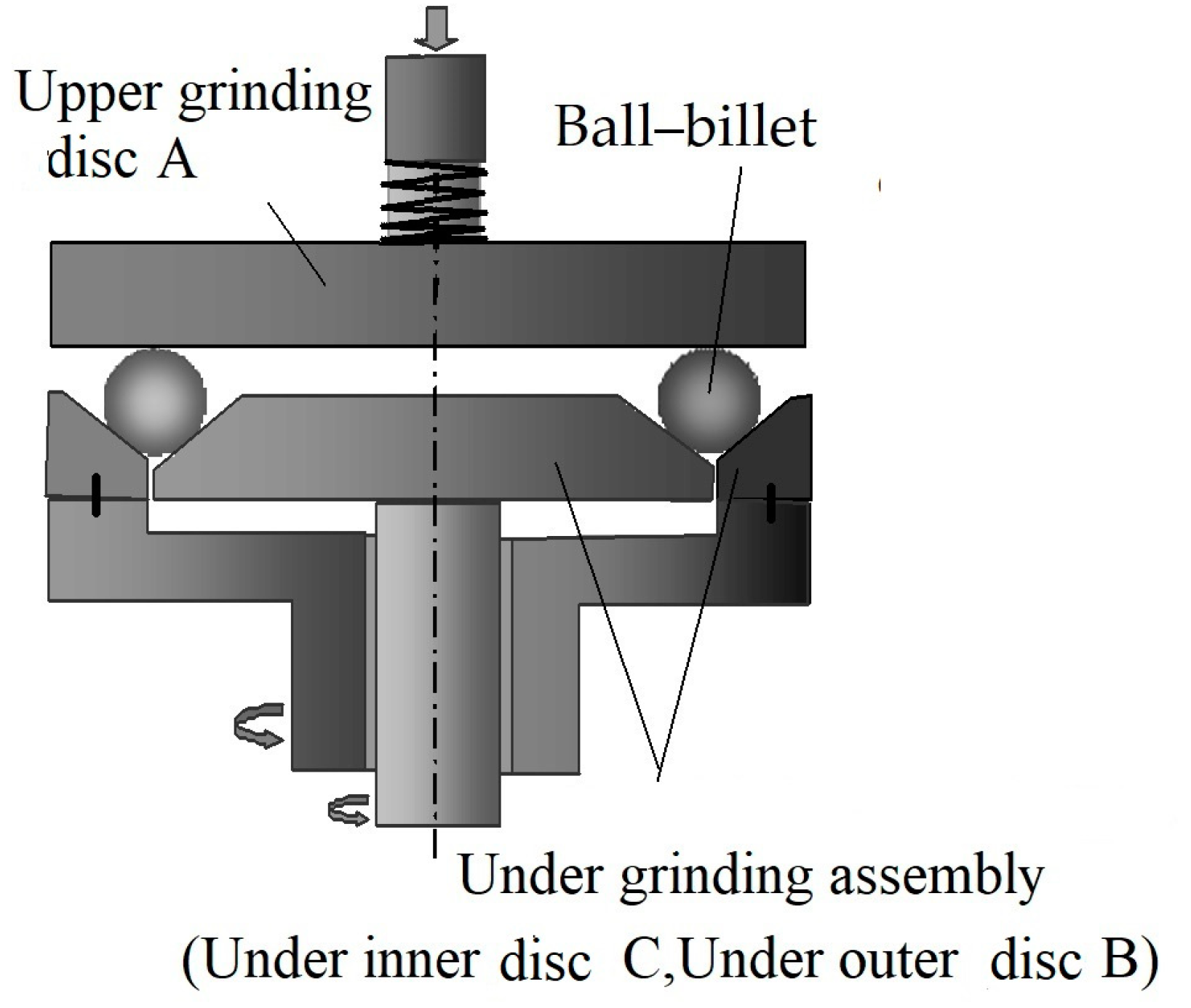
3. Balling Principle of the Three-Body Coupling Grinding Mode

On the basis of the motion equation of a ball–billet under the three-body coupling grinding mode [21,22], the basic grinding principle of precision balls was analyzed in this section. This was used as the theoretical basis to analyze the influencing factors of the three-body coupling grinding mode. Moreover, the motion parameters of a ball–billet under grinding mode with positive control over the rotating angular velocity, traditional V-shaped groove grinding mode, and dual-disc grinding mode were compared.

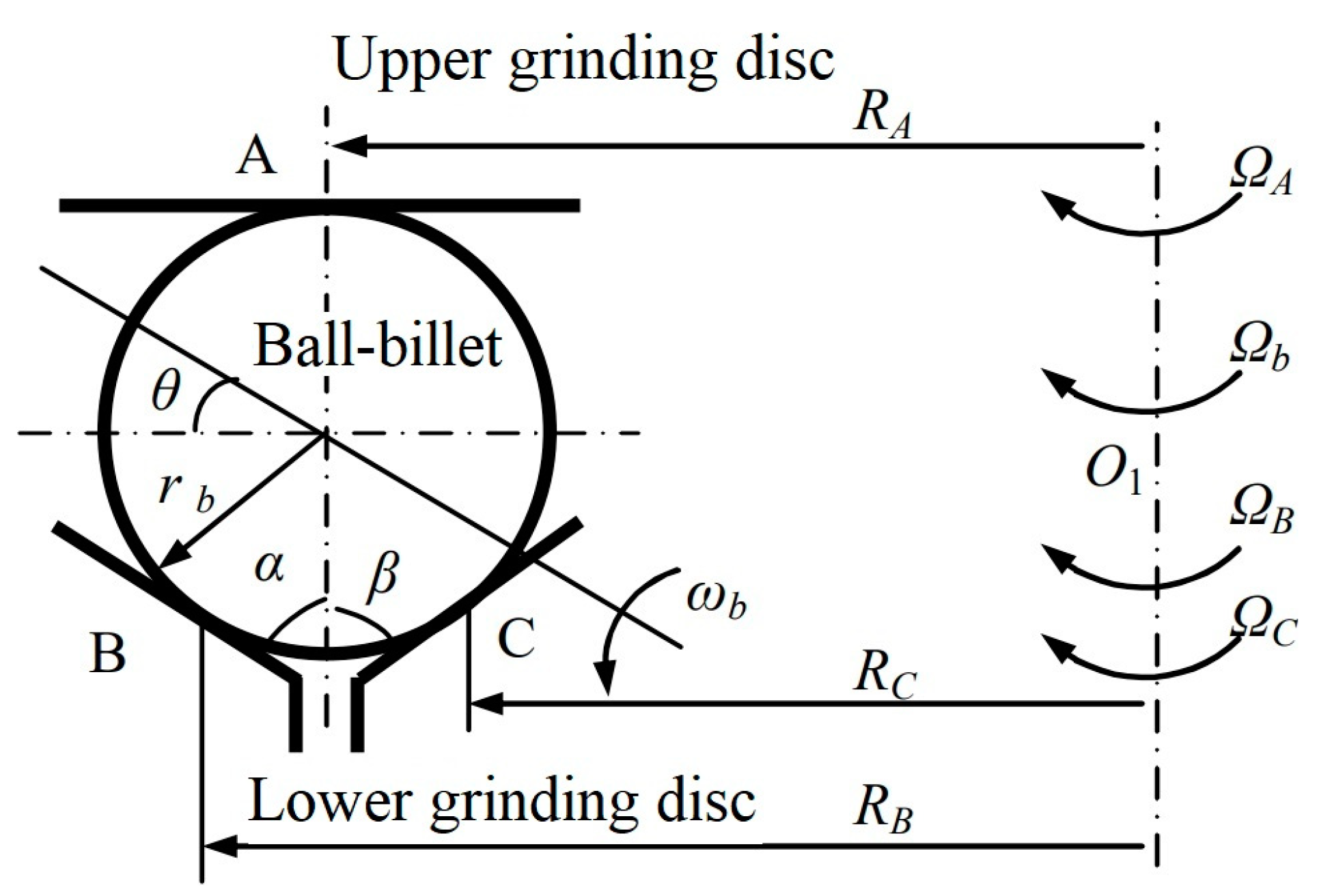
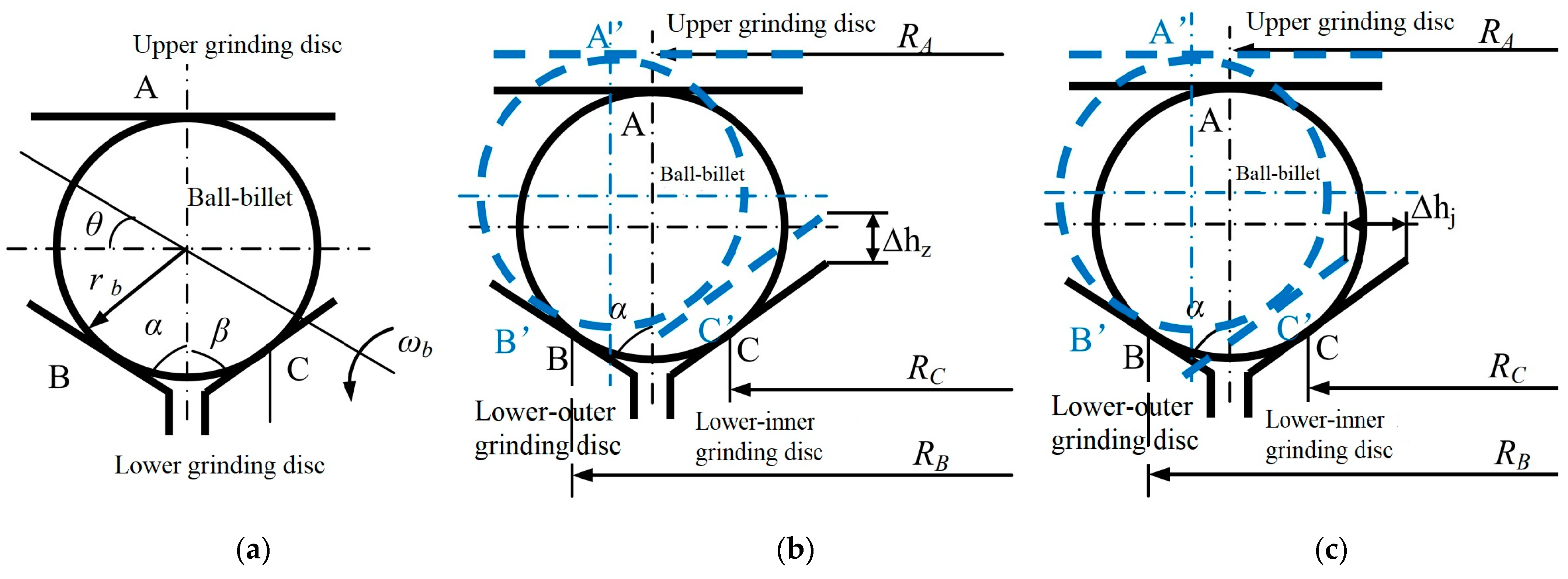
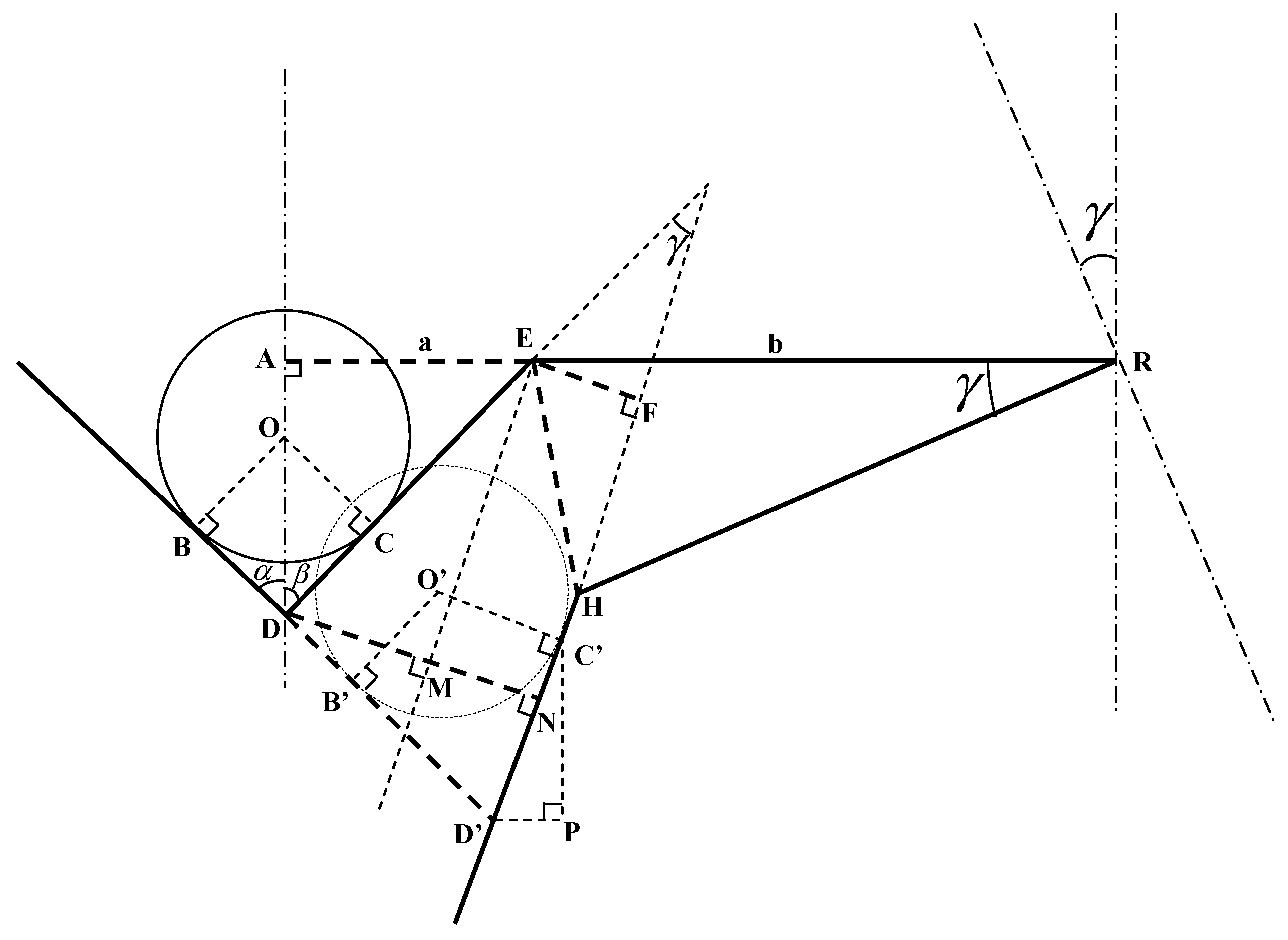
Geometric Motions of a Ball–Billet under the Three-Body Coupling Grinding Mode

Wang and Lv analyzed the geometric motion of a ball–billet under the grinding mode with positive control over the rotating angular velocity [21,22].
As shown in Figure 5, under the grinding mode with positive control over the rotating angular velocity, the processed ball–billet contacts with the grinding disc at points A, B, and C in the V-shaped groove. Specifically, Discs A, B, and C rotate independently, and their rotating speeds are ΩA, ΩB, and ΩC, respectively. The ball–billet makes revolution and rotation under the effects of three points. Relevant parameters are shown in Table 1.
We suppose that the ball in this movement is a “real ball”. In other words, it is a perfect circle at any cross-section and rolls simply. In accordance with this hypothesis, the equilibrium equation set of speed at Points A, B, and C was obtained:
R A Ω A = R A Ω b ω b r b cos θ R B Ω B = R A Ω b + ω b r b sin ( α + θ ) R C Ω C = R A Ω b + ω b r b sin ( β θ )
In practical grinding discs, α = β; therefore,
tan θ = 1 + sin α cos α R B Ω B R C Ω C R B Ω B + R C Ω C 2 R A Ω A Ω b = R B Ω B + R C Ω C 2 R A Ω A sin α 2 R A ( 1 + sin α ) ω b = R B Ω B + R C Ω C 2 R A Ω A 2 r b ( 1 + sin α ) cos θ
When ΩA = 0 and ΩB = ΩC = Ω in Equation (1), it is transformed into the velocity equilibrium equation, i.e., Equation (3), under the V-shaped groove grinding mode. Similarly, θ, Ωb, and ωb can be calculated, as shown in Equation (4).
0 = R A Ω b ω b r b cos θ R B Ω = R A Ω b + ω b r b sin ( α + θ ) R C Ω = R A Ω b + ω b r b sin ( α θ )
θ = tan 1 ( r b R A sin α ) Ω b = R A Ω r b cos ( 1 + sin a ) ω b = Ω 1 + sin α
As shown in Equation (4), θ under the V-shaped groove grinding mode is determined by rb and RA, but it is unrelated to the rotating speed of the grinding disc (Ω) [22]. Given that the geometric parameters of the grinding discs are fixed, the rotating angular velocity of the ball under the V-shaped groove grinding mode is constant. Given rb << RA, θ ≈ 0°. Therefore, a ball–billet can only make a grinding motion with “constant relative direction”. The contact points between a ball–billet and the grinding disc form a group of concentric grinding tracks around the rotating axis of the ball–billet on the ball–billet. Hence, the workpiece cannot be ground uniformly, and the spherical surface cannot achieve uniform grinding quickly.
Similarly, when ΩA = 0 and ΩB ΩC in Equation (1), it is transformed into the velocity equilibrium equation under the three-body coupling grinding mode. In the same way, θ, Ωb, and ωb can be calculated (Equation (5)):
tan θ = 1 + sin α cos α R B Ω B R C Ω C R B Ω B + R C Ω C Ω b = R B Ω B + R C Ω C 2 R A ( 1 + sin α ) ω b = R B Ω B + R C Ω C 2 r b ( 1 + sin α ) cos θ
where 1 + sin α cos α in tan θ is constant, and it is determined by the geometric angle of the grinding disc. Given RB ≈ RC, tan θ is determined by the rotating speed of the grinding disc: Ω B Ω C Ω B + Ω C . Theoretically, tan θ ranges within (−∞, +∞). In other words, θ values within [−90°, 90°]. Thus, grinding tracks can cover the whole spherical surface under dual-disc grinding mode by adjusting ΩB and ΩC of the lower grinding disc. The ball–billet is ground uniformly. The distribution of grinding tracks on the spherical surface is mainly determined by rotating angular velocity and rotating angular velocity, but it is unrelated to the revolving speed of the ball–billet [25,26].

4. Effects of Ball–Billet and Grinding Disc Slip on Rotating Angular Velocity

For the convenience of analysis in the above section, itis hypothesized that no relative motion occurs between the ball–billet and grinding discs (slip-free). However, slip occurs between the ball and grinding discs in practical processing [21,22,23] due to uneven pressures, friction coefficients, and abrasive materials at different contact points between the ball and the grinding discs. The ball–billet may not roll simply as assumed in the ideal conditions. The movement observation of the ball–billet during processing also proves that slip exists at any time. The existence of slip surely influences the motion state of the ball–billet and brings deviations in the angle of rotation, rotating angular velocity, and revolving speed of the ball from the ideal theoretical analysis. Finally, it influences the analysis of grinding uniformity. In this section, key attention is paid to analyzing the relative slip of the ball–billet with the inner and outer discs, as well as the influences of such slip on the grinding uniformity of the spherical surface.

4.1. Relative Slip of the Ball–Billet with Inner and Outer Discs

For the convenience of analysis, the ball–billet is hypothesized to make only relative slippage with the inner disc but has no slip with other grinding discs. In other words, VA = VB = 0 and VC ≠ 0, where VA, VB, and VC are there lative velocities of the grinding discs to the ball.
Here, S C = V C R C Ω C is the sliding–friction ratio between the ball–billet and the inner disc. N t = Ω B Ω C is the rotating speed ratio between inner and outer discs. As shown in Equation (2) [21,45],
Ω b = R B Ω B + R C Ω C 1 S C 2 R A 1 + sin α Ω b Ω C = R B N t + R C 1 S C 2 R A 1 + sin α
tan θ = 1 R B N t + R C 1 S C 1 + sin α cos α × 2 R B N t 1 + sin α cos α
The grinding structural parameters in Table 2 were brought into Equations (6) and (7) for calculation. To disclose the influences of slip on the revolving speed of the ball–billet, a rotating speed relation map was plotted on the basis of the above calculation results by using Ω b / Ω C and the rotating angular velocity as the y-axis and the rotating speed ratio of inner and outer discs (Nt) as the x-axis. Calculation results are shown in Figure 6 and Figure 7. On this basis, the relations between Ω b / Ω C and Nt, as well as that between θ and Nt under different sliding-friction ratios (Sc) between the ball–billet and inner disc, could be concluded. In Figure 6, Nt ranges within [−10, 10]. When Sc = 0, it is the calculation result under no slip between the ball–billet and the grinding disc.
As shown in Figure 7, the influencing degrees of Sc on the motion state of the ball were different when a slip occurred between the ball–billet and the inner disc. With the increase in Sc, the influencing degrees of the rotating speed of the inner disc on the rotating angular velocity and the revolving speed of the ball–billet are decreased. When Sc = 1, the relative movement velocity between the ball–billet and the inner disc was equal to the linear velocity on the grinding disc. In other words, the rotation of the inner disc may not cause ball movement. The ball–billet and the grinding discs are considered in the state of complete slip. The relation curve in Figure 6 passes through the origin (0, 0), and Ω b / Ω C = 0. At this moment, the rotation of the outer disc directly determines the motion state of the ball–billet. In Figure 7, the rotating angular velocity may not change with Nt but is a constant. With the increase in Sc, Nt can decrease relatively when θ can change comprehensively within [−90°, 90°]. However, the variation degree of θ is intensified. As shown in Figure 7, when Sc = 0, it means that the ball blank and the grinding disc do not slide; when Sc = 1, it means that the ball blank and the grinding disc are in a state of complete skid, and the curve in the middle represents the intermediate transition state.

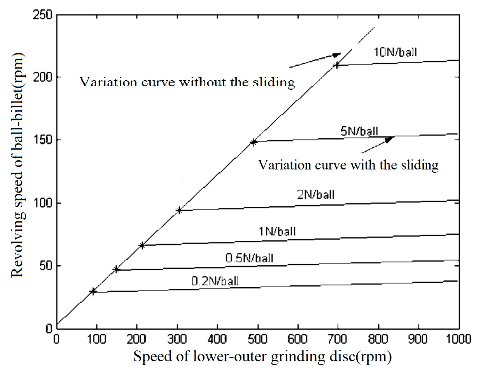
4.2. Relative Sliding between theBall–Billet and the Outer Disc

This study sets the sliding between the ball–billet and the outer disc only. In other words, V A = V C = 0 and V B 0 . Similarly, the relation between Ω b / Ω C = 0 and Nt, as well as that between θ and Nt, can be deduced from Equation (2), as shown in Equations (8) and (9).
Ω b Ω C = R B N t 1 S B + R C 2 R A 1 + sin α
tan θ = 1 S B R C R B N t + 1 S B 1 + sin α cos α × 2 1 + sin α cos α
where S B = V B R B Ω B is the sliding–friction ratio between the ball–billet and the outer disc. The structural parameters in Table 2 were brought into Equations (8) and (9). Based on calculation results, Figure 8 can be plotted.
Similar to the analys is in the above section, the following conclusions are drawn:
(1)
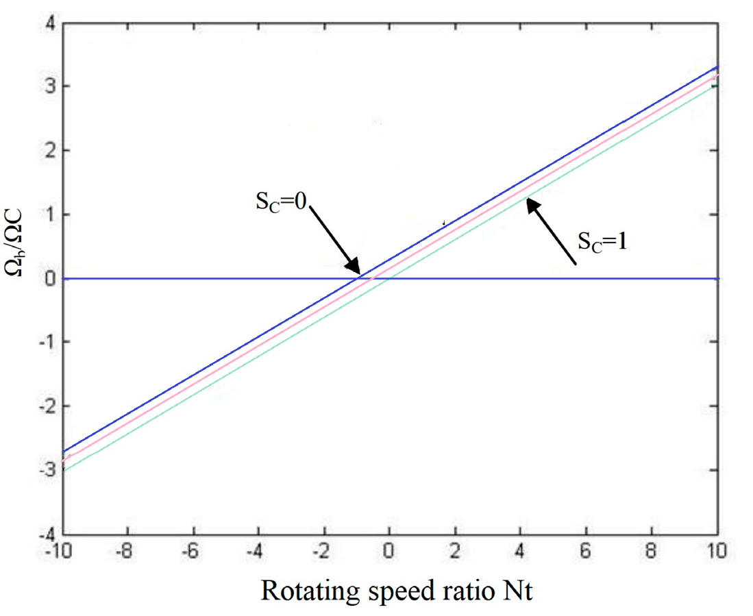
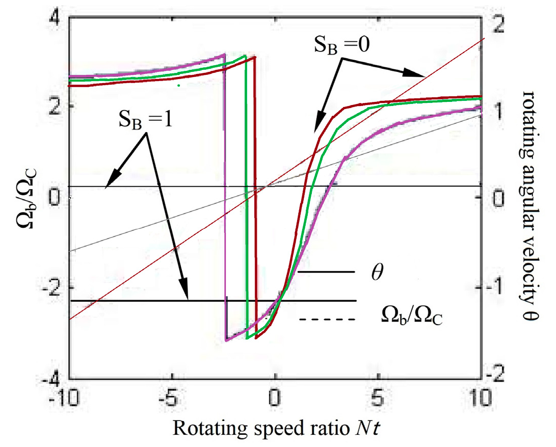
With the increase in the sliding–friction ratio between the ball–billet and the outer disc (SB), the slope of the relation curve between Ω b / Ω C and Nt decreases gradually. However, the intersection point between the relation curve and the y-axis is kept constant under different SB. When SB = 0, Ω b / Ω C is a constant value. When SB ≠ 0, Ω b / Ω C increases with the increase in Nt. This result demonstrates that when the rotating speed of the inner disc is constant, the revolving angular speed (Ωb) of the ball–billet may also increase with the increase in Nt. The variation of the revolving speed of the ball–billet is intensified with the decrease in SB;
(2)
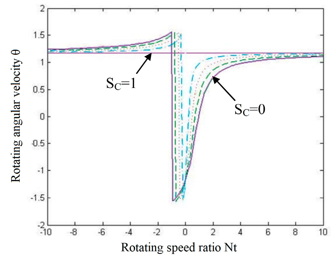
With the reduction in SB, the ball–billet can realize the variation of rotating angular velocity within [−90°, 90°] in the relatively small variation range of Nt. When complete slippage occurs between the ball and the outer disc (SB = 1), the motion state of the ball–billet is completely determined by the inner disc, and θ is a constant value.
Based on the above analysis, the relative sliding behavior of the ball–billet with inner and outer discs have similar influences on the motion state of the ball–billet. Given that the slippage between the ball–billet and grinding discs has direct influences on the variations of the rotating angular velocity, revolving speed, and other kinetic parameters, it influences the distribution of the grinding tracks on the spherical surface directly. Such influencing degree can be analyzed by the sliding-friction ratio between the ball–billet and the grinding discs.

4.3. Critical Conditions of Relative Slippage Betweenthe Ball–Billet and the Grinding Discs

The only effects of relative slippage between the ball–billet and grinding discs on the motion of the ball–billet have been discussed in the above section. In practical processing, complicated factors, including the friction coefficient between ball–billet and grinding discs, loads of ball–billet, processing precision of rollaway of the grinding disc, distribution of grinding liquid, viscosity of grinding liquid, and so on, may cause such relative motion. In this study, stress relation during the motion of ball–billet was analyzed to investigate the causes and critical conditions for relative motion between the ball–billet and grinding discs.
The frictional forces between the ball–billet and three contact positions of the grinding discs were FA, FB, and FC:
F A = W A μ A F B = W B μ B F C = W C μ C
To analyze the critical conditions for the sliding of the ball–billet, it is hypothesized that frictional force can ensure a slip-free motion of the ball–billet, and the frictional force between the ball–billet and the grinding disc reaches the maximum. According to the relation equation of gyroscopic moment during the motion of the ball–billet,
[ M ]   =   I Ω b ω b c o s   θ   =   ( F A   +   F B   +   F C )   r b   =   ( W A   μ A   +   W B   μ B   +   W C   μ C )   r b ,
Where [M*] is the critical gyroscopic moment when the frictional force can guarantee the slip-free motion of the ball–billet. Given the fixed processing loads, the frictional force produced by the grinding disc and ball–billet has some limits. This decides that the gyroscopic moment on the ball–billet has some limit. In other words, the rotating angular velocity and revolving speed of the ball–billet cannot be increased infinitely during processing. However, the rotating speed (it is not increased infinitely, but it can achieve a high rotating speed for the ball–billet) cannot be increased continuously during grinding under the effect of an external driving device. In summary, some critical value of rotating speed exists between the ball–billet and grinding discs under some processing conditions. Under ideal conditions, no relative slippage occurs between the ball–billet and grinding disc when the rotating speed of the grinding disc is lower than the critical value. Under this circumstance, the rotating angular velocity and revolving speed of the ball–billet may increase with the increase in the rotating speed of the grinding disc. When the rotating speed of the grinding disc exceeds such a critical value, the rotating angular velocity and revolving speed of the ball–billet may not increase with the increase in rotating speed, thus having relative slippage. This critical speed is related to the frictional coefficient and processing loads. The higher frictional coefficient and processing loads lead to higher critical speed.
For the convenience of analysis, the processing structure is hypothesized to be an ideal mechanism without errors. Hence,
I Ω b w b cos θ = W A μ A + W B μ B + W C μ C r b m b R C Ω C 2 R B R C N t + 1 2 10 R A 1 + sin α 2 = W A μ A + W B μ B + W C μ C r b
Here, the Ø10 mm ball was chosen as the analysis object (mb = 10 g). Parameters in Table 2 were brought in to analyze under loading conditions of 1 N/ball and 2 N/ball. In this section, the frictional coefficients between the ball and three grinding discs are the same on the three contacting points. With references to the frictional coefficient among various materials [45] and previous research results [46], the frictional coefficient between the ball–billet and the grinding disc was set to 0.1. The above parameter settings were applied, and the critical rotating speed of the grinding disc under different loading conditions could be calculated. The relation curve between the critical rotating speeds of the inner and outer discs and NtBC) is shown in Figure 9.
The rotating speed of the outer disc in correspondence to the inner disc is positively related to Nt. Therefore, the critical rotating speed of the ball–billet and the inner disc is lower. Given a higher processing load, the produced frictional force is higher, and it can provide a greater gyrostatic moment; thus, the ball–billet and revolving speed that the ball–billet can undertake are greater. As a result, the corresponding critical rotating speed is higher.

4.4. Motion Characteristics of Balls under the Sliding State

According to Johansson et al. [35], the frictional force between the ball–billet and the grinding disc could be calculated in accordance with a relative sliding speed. Based on the above analysis, the relative sliding velocities at three contact points between the ball–billet and grinding disc are VA, VB, and VC.
V A = R A Ω b ω b r r b V B = R B Ω B R A Ω b r b ω b r sin α + ω b z cos α V C = R C Ω C R A Ω b r b ω b r sin β ω b z cos β
Based on previous studies [21,22], the components of rotating speeds (perpendicular to the grinding disc surface) and rolling speeds (parallel to the grinding disc surface) at three contact points between the ball–billet and grinding disc are
ω s , A = ω b sin θ ω s , B = ω b cos ( α + θ ) + Ω B sin α ω s , C = ω b cos ( α θ ) + Ω C sin α ω r , A = ω b cos θ ω r , B = ω b sin ( α + θ ) + Ω B cos α ω r , C = ω b sin ( α θ ) + Ω C cos α
The calculation formulas of frictional force (Fi) and torque (Mi) under sliding conditions are deduced in Reference [46]:
F i / ( μ i W i ) = tanh [ 1.275 ( e i / a i ) ( tanh ( 0.47 χ i ) n ) 1 / n ] [ F i / ( μ i W i ) ] 2 + { M i / [ 0.56 ( tanh ( 0.3 χ i ) n ) 1 / n ] μ i a i W i } 1.5 = 1.0
where Wi denotes the processing loads, Fi is the frictional force, Mi is the friction torque, and n refers to a correction index. According to references [46,47], n = 2. Then,
F i = μ i W i tanh [ 1.275 ( e i / a i ) ( tanh ( 0.47 χ i ) 2 ) 1 / 2 ] M i = 0.56 μ i a i W i 1 F i μ i W i 2 2 3 tanh 0.3 χ i 2 1 2
where a refers to the Hertz contact radius on contact points between the ball–billet and grinding discs, and a i = 0.75 W i r B E i 1 3 . e refers to the eccentric moment of the spin axis and the contact point centers of the ball–billet in its contact regions with the grinding disc. Moreover, e i = V i / ω s , i .
Equation (14) was brought in, and Equation (16) could calculate the mechanical equilibrium equation when some relative slippage occurs between the ball–billet and the grinding disc.
W B sin α + W C sin α G W A F B cos α + F C cos a = 0 R F A + F C sin α + F B sin α + W B cos α W C cos α = 0 ( F A + F B + F c ) r b M = 0
In the above text, the frictional force and frictional torque on the contact points between the ball–billet and grinding disc were brought into Equation (17) to calculate the rotating angular velocity and revolving angular velocity of the ball–billet under this circumstance. The variation of the revolving speed of the ball–billet with the rotating speed of the outer disc under different loading conditions when the rotating speed of the inner disc is fixed at 10 rpm is shown in Figure 10. The ideal variations of the revolving speed with loads are the same curve, and the revolving speed increases with the increase in the rotating speed of the outer disc. Given frictional force, the critical rotating speeds of the grinding disc under different loads vary. The critical rotating speed is positively related to processing loads. When the rotating speed of the grinding discs is lower than the critical rotating speed, the rotating speed and revolving speed of the ball–billet increase quickly. When the rotating speed of the grinding disc exceeds the critical value, the growth amplitude of the revolving speed of the ball–billet decreases sharply due to the slow increase in frictional force between the ball–billet and the grinding disc with the relative sliding speed.

5. Effects of Mechanism Error on the Rotating Angular Velocity of the Ball

The above analyses hypothesize that the processing structure is in the ideal state, and no structural errors are found. Given manufacturing and assembly errors, having some errors in practical processing mechanisms, such as run-out and tilt of grinding discs, is inevitable. Therefore, the manufacturing and assembly accuracy of the processing structure influence the motion of the ball–billet, thus influencing the machining effect of the ball–billet. In this section, the effects of geometric errors (e.g., face run-out, tilt, and groove of the grinding surface) on the grinding process are discussed. To analyze the influencing degrees of various mechanism errors on grinding uniformity, a numerical model simulation was applied.

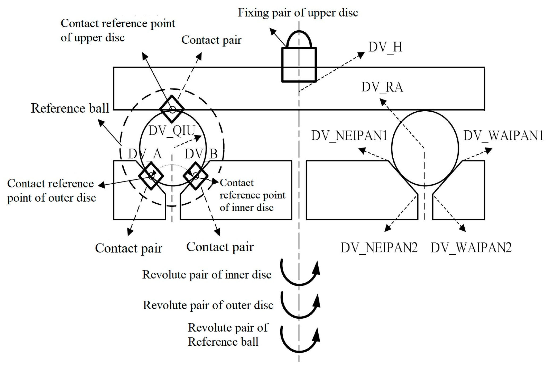
5.1. Establishing the ADAMS Numerical Simulation Model

In this study, a numerical model of a three-body coupling grinding mode was constructed on the basis of the Automatic Dynamic Analysis of Mechanical System (ADAMS) developed by MSC. This software can easily conduct nonlinear kinetic analysis, and it has an advanced numerical analytical technology. It is convenient for the parameter analysis of mechanical system performance, and it meets the requirements of the simulation analysis of the three-body coupling grinding process [30,48]. Hence, the optimal mixing ratio between the mechanical parameters of grinding discs and the diameter of the processing ball was determined on the basis of this numerical model. Moreover, the relationship between various motion states and the grinding uniformity of the ball during the grinding process was analyzed.
The 3B-CGM numerical model is established, and the ADAMS numerical simulation model is shown in Figure 11. The variables of parameterized points are shown in Table 3.
To make the simulation analysis results of the ADAMS numerical model of the three-body coupling grinding agree with practical processing results as much as possible, the balling geometry and motion states under the three-body coupling grinding mode were analyzed. Moreover, the grinding was in the finish machining stage, when the material removal and geometric shape of the ball changed slightly. Hence, the following simulation conditions were made to model the three-body coupling grinding mode [30,48,49]:
  • Ignore the corrosion of the grinding fluid or chemical reactions caused by friction during grinding;
  • Ignore the material removal effect;
  • A single ideal real ball is used as the analysis object;
  • Rigid contact occurs between the ball and grinding discs without relative slippage.
Additionally, the revolving and rotating states of the ball center in the ground coordinate system were calculated by using the system measuring function in the ADAMS software. Meanwhile, the revolute pairs and driving were added to the reference ball in the model to solve the problem in the motion state measurement at contact points. Data of the revolving angular speed of the ball center was input into the driving. Finally, the coordinates of the reference points were transformed into the coordinate system of the ball center from the ground coordinate system, thus enabling the plotting of the grinding tracks of the ball [30,48,49].
To study whether grinding tracks cover the spherical surface uniformly, a triangular meshing technique was applied (Figure 12) to divide the spherical surface into several triangular zones with the same shape and area. In accordance with the simulation results of grinding tracks, the grinding track points were sampled regularly. Then, a statistical analysis of the quantity of grinding track points in each triangular zone was conducted. The standard deviation (S) of the quantity of grinding track points in each region was calculated to characterize grinding uniformity. The higher S value indicates the poorer distribution uniformity of the grinding track points.
In this model, the single-factor analysis method was applied. The inner disc diameter and ball diameter were changed successively during simulation grinding to obtain distribution maps of grinding track points under several groups of different ratios between ball diameters and disc diameter. Moreover, the S of the quantity of grinding track points was calculated. The distribution map of grinding track points under different groove angles and the corresponding S was acquired.

5.2. Effects of Run-Out of Lower Grinding Disc

The face run-out of the lower grinding disc is mainly caused by the manufacturing and assembly errors of parts. The face run-out of the lower grinding disc influences loads on the ball–billet and its motion state directly. The impacts of loads cause adverse influences on the processing accuracy of the ball–billet and the quality of the spherical surface. Under the three-body coupling grinding mode, the lower grinding disc is divided into two discs, with inconsistent run-out directions, thus easily causing load changes and, thereby, influencing sphericity.
The face run-out of the lower grinding disc can be attributed to axial and radial run-outs. The influences of the axial run-out and radial run-out of the inner disc on the contact state of the ball–billet are shown in Figure 13.
Similar results are observed in the run-out of the outer disc [26]. Therefore, only the situation when the inner disc faced run-out was examined here. Moreover, the upper grinding disc of the processing equipment was in the elastic pressure state and could move vertically. Given the existence of mechanism error, the contact points between the ball–billet and grinding disc were inconsistent with the ideal contact positions. The practical contact points were A′, B′, and C′, respectively. Accordingly, the distances from the three contact points to the rotating axis of the grinding disc were RA′, RB′, and RC′, respectively. Hence, the axial run-out distance of the inner disc was ∆hz, and α = β, R A = R A + sin α 2 cos α Δ h z . Moreover,
R B = R A + r b cos α = R A + sin α 2 cos α Δ h z + r b cos α R C = R A r b cos α = R A + sin α 2 cos α Δ h z r b cos α
Equation (18) was brought into Equation (2), and
tan θ = 1 + sin α cos α ( R A + sin α 2 cos α Δ h z + r b cos α ) ω B ( R A + sin α 2 cos α Δ h z r b cos α ) ω C ( R A + sin α 2 cos α Δ h z + r b cos α ) ω B + ( R A + sin α 2 cos α Δ h z r b cos α ) ω C ω = ( R A + sin α 2 cos α Δ h z + r b cos α ) ω B + ( R A + sin α 2 cos α Δ h z r b cos α ) ω C 2 ( R A + sin α 2 cos α Δ h z ) ( 1 + sin α ) ω b = ( R A + sin α 2 cos α Δ h z + r b cos α ) ω B + ( R A + sin α 2 cos α Δ h z r b cos α ) ω C 2 r b ( 1 + sin α ) cos θ
Similarly, given a radial run-out value of ∆hj, R A = R A + 1 2 Δ h j . Therefore,
R B = R A + r b cos α = R A + 1 2 Δ h j + r b cos α R C = R A r b cos α = R A + 1 2 Δ h j r b cos α
Equation (20) was brought into Equation (2). Therefore, Equation (21) can be deduced as follows:
tan θ = 1 + sin α cos α ( R A + 1 2 Δ h j + r b cos α ) ω B ( R A + 1 2 Δ h j r b cos α ) ω C ( R A + 1 2 Δ h j + r b cos α ) ω B + ( R A + 1 2 Δ h j r b cos α ) ω C ω = ( R A + 1 2 Δ h j + r b cos α ) ω B + ( R A + 1 2 Δ h j r b cos α ) ω C 2 ( R A + 1 2 Δ h j ) ( 1 + sin α ) ω b = ( R A + 1 2 Δ h j + r b cos α ) ω B + ( R A + 1 2 Δ h j r b cos α ) ω C 2 r b ( 1 + sin α ) cos θ
As shown in Equation (21), when the lower grinding disc has face run-out, the geometric kinematic equation of the ball is the same as the original one. To study the influences of run-out on the grinding of the ball, MATLAB was applied for simulation.
Table 4 shows the setting conditions of simulation, ∆hz and ∆hj are distributions of grinding tracks on the spherical surface at ±2, ±1, and ±0.1 mm. Specifically, the radial unidirection was removed because the disc was symmetric. Figure 14 shows the distribution of spherical grinding trajectory under different end-hop conditions. The distribution of grinding tracks on the spherical surface when ∆hz = 0 and ∆hj = 0 is the distribution of grinding tracks under ideal conditions (no face run-out in the grinding disc).
Effects of face run-out of inner disc. Table 5 shows that when the lower grinding disc has axial and radial run-outs, STD changed slightly compared with that under ideal conditions. The spherical surface is covered by grinding the tracks uniformly.

5.3. Effects of the Tilt of the Lower Grinding Disc

Given that manufacturing and assembly errors and uneven stress during processing may cause some tilt of the grinding disc (nonperpendicularity to the axial direction of the principal axis), this may also change the motion state of the ball–billet and change the distribution of the grinding tracks on the spherical surface. In this section, the tilt of the inner disc was investigated, as shown in Figure 15. The situation of the outer disc tilt is similar to the situation of the inner disc tilt, and it is not discussed in this section.
The geometric relation of the influences of the inner disc tilt (γ) on the contact points of the ball–billet is shown in Figure 16. In Figure 16, R is a point on the rotating axis of the grinding disc. D-E-R refers to the position of the inner disc under ideal conditions, and B-D-E refers to the V-shaped rollaway under ideal conditions. D’-H-R refers to the position of the inclined inner disc, and B’-D’-H is the tracks after the inclination of the inner disc. The ball center points before and after the inclination of the inner disc are O and O’, respectively. When the inner disc has no tilt, the groove angles are α = β = 45°. EM is parallel to NH. Here, if A E = a and E R = b, then a + b = RA, and E D = 2 a . According to Figure 16, it can obtain
E H ¯ = 2 E R ¯ sin E R H 2 = 2 b sin γ 2
E F ¯ = E H ¯ sin E H F = 2 b sin γ 2 sin ( π 4 γ 2 )
D M ¯ = D E ¯ sin D E M = 2 a sin γ
D D ¯ = D N ¯ sin D D N = D M ¯ + E F ¯ sin D D N = 2 a sin γ + 2 b sin γ 2 sin ( π 4 γ 2 ) sin ( π 2 γ )
B D ¯ = B O ¯ cot B D O = r b cot ( π 4 γ 2 )
O O ¯ = B B ¯ = D D ¯ B D ¯ + B D ¯ = 2 a sin γ + 2 b sin γ 2 sin ( π 4 γ 2 ) sin ( π 2 γ ) r b cot ( π 4 γ 2 ) + r b
It can deduce geometric parameters when the inner disc inclines:
R A = R A O O ¯ 2 = R A 2 a sin γ + 2 b sin γ 2 sin ( π 4 γ 2 ) 2 cos γ + r b cot ( π 4 γ 2 ) 2 r b 2 R B = R A + r b cos α = R A 2 a sin γ + 2 b sin γ 2 sin ( π 4 γ 2 ) 2 cos γ + r b cot ( π 4 γ 2 ) 2 R C = R A D D ¯ 2 B D ¯ sin D C P = R A 2 a sin γ + 2 b sin γ 2 sin ( π 4 γ 2 ) 2 cos γ r b cot ( π 4 γ 2 ) sin ( π 4 γ )
By bringing it into Equation (2), it can obtain
tan θ = 1 + 2 R A a tan γ 2 b cos γ sin γ 2 sin ( π 4 γ 2 ) + 2 2 r b cot ( π 4 γ 2 ) ω B R A a tan γ 2 b cos γ sin γ 2 sin ( π 4 γ 2 ) r b cot ( π 4 γ 2 ) sin ( π 4 γ ) ω C R A a tan γ 2 b cos γ sin γ 2 sin ( π 4 γ 2 ) + 2 2 r b cot ( π 4 γ 2 ) ω B + R A a tan γ 2 b cos γ sin γ 2 sin ( π 4 γ 2 ) r b cot ( π 4 γ 2 ) sin ( π 4 γ ) ω C ω = R A a tan γ 2 b cos γ sin γ 2 sin ( π 4 γ 2 ) + 2 2 r b cot ( π 4 γ 2 ) ω B + R A a tan γ 2 b cos γ sin γ 2 sin ( π 4 γ 2 ) r b cot ( π 4 γ 2 ) sin ( π 4 γ ) ω C ( 2 + 2 ) R A a tan γ 2 b cos γ sin γ 2 sin ( π 4 γ 2 ) + 2 r b 2 cot ( π 4 γ 2 ) 2 r b 2 ω b = R A a tan γ 2 b cos γ sin γ 2 sin ( π 4 γ 2 ) + 2 2 r b cot ( π 4 γ 2 ) ω B + R A a tan γ 2 b cos γ sin γ 2 sin ( π 4 γ 2 ) r b cot ( π 4 γ 2 ) sin ( π 4 γ ) ω C ( 2 + 2 ) r b cos θ
The STD of the spherical grinding tracks under different γ is conducted in accordance with simulation data.
Table 6 shows the simulation analysis conditions when the inner disc of the lower grinding disc is tilted. Effects of inner disc tilt. Table 7 shows that STD increases with the increase in tilt degree, and the growth amplitude increases. In particular, when γ is higher than 1°, the worsening trend of sphericity is intensified, thus demonstrating that the grinding disc tilt may cause adverse effects on the grinding uniformity of the ball–billet. In practical processing, the tilt of the grinding disc shall be eliminated as much as possible. The distribution of grinding tracks on the spherical surface under different γ is shown in Figure 17.

5.4. Effects of Orbital Geometric Accuracy

During processing, given that the ball–billet is put in the orbit of the lower grinding disc, the geometric accuracy of the orbit directly influences the processing of the ball–billet. Given the existence of processing errors, the practical orbit is not an ideal circular ring. For the convenience of analysis, itis hypothesized that several uplifts are found on the grinding disc, which influences the geometric accuracy of the grinding orbit. The orbits with two and three uplifts are shown in Figure 18.
Given that the orbit has uplifts, the ball–billet is lifted up by these uplifts when it arrives at the positions; thus, ball–billets at these positions are higher than the others. Hence, ball–billets at these positions undertake more loads than the balls in other parts.
To comprehend the effects of the out-of-roundness of the grinding disc on grinding track points, MATLAB simulation was conducted in accordance with the simulation conditions (Table 8). Simulation results are shown in Figure 19. The STD of spherical grinding uniformity is shown in Table 9.
Table 9 shows that the effects of the geometric precision of orbits on the STD of spherical grinding uniformity show no laws. However, the worsening degree of sphericity influences spherical grinding uniformity more than disc tilt and face run-out, and it has adverse effects on grinding uniformity. In practical processing, the orbital preloading of the ball–billet was applied to improve the geometric precision of orbits and eliminatetheadverse effects of roundness errors as much as possible. The orbit distribution of spherical surfaces when the outer disc is not round is shown in Figure 19.
In the above-investigated mechanism error of dual-revolving grinding equipment, grinding uniformity was influenced greatly when the outer disc was not round, and it failed to grind into balls when the error parameter d was higher than 0.3 mm. The rest of the errors might also influence spherical grinding uniformity to some extent, and such influences were relatively small. When some mechanism errors occurred, the grinding uniformity of the ball–billet was even slightly better than that under the ideal three-body coupling grinding mode (e.g., when ∆hz = 0.1 mm or ∆hj = 0.1 mm; or when γ = 0.5° and γ = 1°). This result might be because, given a small mechanism error and no adverse effects on the ball–billet processing, the rotating sliding of the ball–billet in relation to the rolling of the grinding disc was intensified, which accelerated the variation of θ. As a result, grinding track lines could cover the ball–billet surface more uniformly.

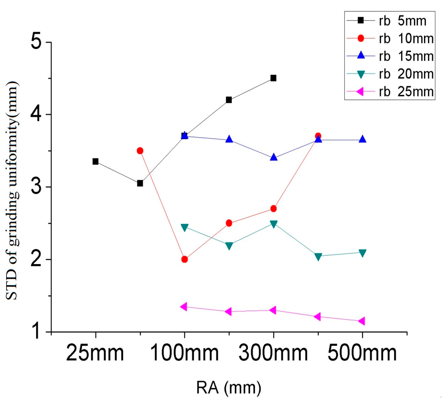
5.5. Effects of Inner Disc Diameter

The processing ranges of the dual-rotation grinding device were set as RA (25, 50, 100, 200, 300, 400, 500 mm) and rb (5, 10, 15, 20, 25 mm). On this basis, the corresponding S of the spherical grinding uniformity was obtained. The simulation time was set to t = 20 s and step = 200. The rotating speed of the inner disc used the relatively mature triangular wave rotating speed curves in early studies (Figure 20).
The S values of spherical grinding uniformity under different rb and RA are shown in Figure 21 (RA ranges from 25 mm to 500 mm). As can be seen from the figure, the simulation curve of each ball diameter corresponds to a disk diameter with the minimum standard deviation S of uniformity (as shown in Table 10), so the selection of disk diameter should be one-to-one corresponding to the ball diameter.

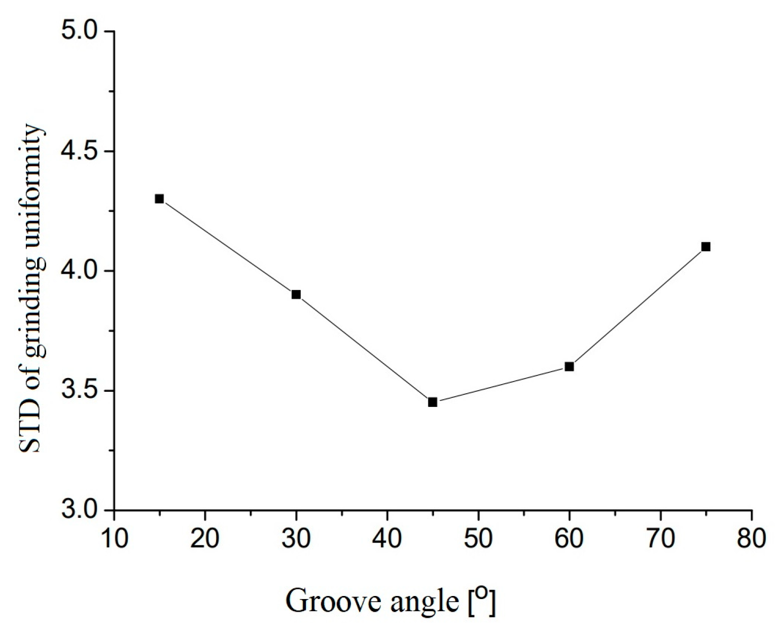
5.6. Effects of Groove Angle

During the balling process under the three-body coupling grinding mode, the V-shaped groove angles also had great influences on the grinding uniformity of the processing ball. To determine the optimal angle, a simulation study under different groove angles was conducted. The simulation conditions are shown in Table 11.
Under the three-body coupling grinding mode, the groove angle in the lower grinding disc was changed successively to 15°, 30°, 45°, 60°, and 75° to simulate the numerical values of sphericity variations. The standard deviation was relatively small when the groove angle was between 45° and 60°. In practical processing, the groove angle was generally 45° (Figure 22).

6. Conclusions

In this paper, the factors influencing the grinding uniformity of a precision ball under the three-body coupling grinding method (3B-CGM) were analyzed step by step. Firstly, the reason for the sliding state was analyzed, and the mathematical model of the critical condition of the sliding state was analyzed so that the sliding state could be controlled. Furthermore, the causes and degree of mechanical errors, such as disc run out, disc tilt, and track error of the grinding uniformity, are analyzed, and the numerical reference of the degree of influence of these errors is given. Finally, the reasons for the influence of disk diameter and groove angle on the grinding uniformity are analyzed, and the analysis method of selecting the best matching parameters and the reference value of the optimal parameters are given. In the process of analysis, the standard deviation STD of trajectory point uniformity of spherical grinding was introduced to provide feedback on the accuracy of the mathematical model. In this paper, the accurate motion control model and the optimal parameter analysis method are established, which improves the fine control ability of the 3B-CGM motion state, and lays a theoretical foundation for the grinding effect approaching to the ideal condition in actual mass production.

Author Contributions

Conceptualization, W.Y. and B.L.; methodology, W.Y.; software, W.Y.; formal analysis, B. L.; investigation, B. L.; resources, J.Y.; data curation, W.Y.; writing—original draft preparation, W.Y.; writing—review and editing, W.Y.; visualization, J.Y.; project administration, J.Y. All authors have read and agreed to the published version of the manuscript.

Funding

Public Welfare Program of Zhejiang Province (LGG22F030013); Natural Science Foundation of Zhejiang Province (LZY23E050003).

Institutional Review Board Statement

The study did not require ethical approval.

Informed Consent Statement

Not applicable.

Data Availability Statement

Not applicable.

Conflicts of Interest

The authors declare no conflict of interest.

References

  1. Chen, Y.J.; Tsai, J.C.; Hsu, Y.C. A real-time surface inspection system for precision steel balls based on machine vision. Meas. Sci. Technol. 2016, 27, 074010. [Google Scholar] [CrossRef]
  2. Hu, L.; Zha, J.; Zhao, W.H.; Peng, X.F.; Chen, Y.L. Multi-dimensional controllability analysis of precision ball bearing integrity. Adv. Manuf. 2022, 27, 449–452. [Google Scholar] [CrossRef]
  3. Zhang, K. Discussion on new Rolling Bearing of Japanese NSK. Bearings 2000, 9, 36–39. [Google Scholar]
  4. Maeda, Y. Development of high precision silicon nitride balls. Koyo Eng. J. 2001, 158E, 42–44. [Google Scholar]
  5. Wang, G.; Wang, Y. Research Progress on Ceramic Ball Bearing for Shaft of High-speed Digital Control Machine. Bearings 2003, 9, 41–59. [Google Scholar]
  6. Zhao, J.J.; Lin, M.X.; Song, X.C.; Guo, Q.Z.; Zhao, J.J.; Lin, M.X.; Song, X.C.; Guo, Q.Z. Analysis of the precision sustainability of the preload double-nut ball screw with consideration of the raceway wear. Proc. Inst. Mech. Eng. Part J J. Eng. Tribol. 2019, 234, 1530–1546. [Google Scholar] [CrossRef]
  7. Cheng, Q.; Qi, B.B.; Chu, H.Y.; Zhang, Z.L.; Liu, Z.F.; Zheng, J.G. The analysis on the influence of mixed sliding-rolling motion mode to precision degradation of ball screw. Proc. Inst. Mech. Eng. Part C J. Mech. Eng. Sci. 2022, 236, 669–688. [Google Scholar] [CrossRef]
  8. Huang, B.W.; Kung, H.K. Variations of instability in a rotating spindle system with various bearings. Int. J. Mech. Sci. 2003, 45, 57–72. [Google Scholar] [CrossRef]
  9. Xiao, X.; Yan, Q.; Lin, H.; Jiao, J.; Liu, J. Research Progresses on Grinding and Polishing Technology of Silicon Nitride Ceramic Balls. J. Guangdong Univ. Technol. 2018, 6, 18–23. [Google Scholar]
  10. Guo, W.; Yuan, J.; Xiang, Z.; Zhou, F.; Lv, B.; Zhao, P. Spheroidal Machining Test Based on Variable Turning Curvature Grinding Method with Single Turntable. Surf. Technol. 2018, 7, 252–258. [Google Scholar]
  11. Guo, W.; Yuan, J.; Xiang, Z.; Lv, B.; Zhao, P.; Zhou, F. Experiment on process parameters for material removal of high-precision balls by spiral groove lapping plate. Electromech. Eng. 2018, 10, 1058–1062. [Google Scholar]
  12. Nie, L.; Zhao, X. Discussion on Steel Balling Conditions and Influencing Factors. Bearings 2001, 1, 16–18. [Google Scholar]
  13. Rascher, R. Technical Status and Development Trend of Grinding Steel Balls. Foreign Bear. 1992, 3, 38–42. [Google Scholar]
  14. Zhang, K.; Wang, H.; Sun, J. Research on Superfinishing Simulation and Test of Silicon Nitride Ceramic Ball Bearing Grooves. Ordnance Mater. Sci. Eng. 2019, 4, 49–54. [Google Scholar]
  15. Chen, B.; Wei, Z.; Li, B.; Wang, Z.; Wang, T. Research and Application Progresses of Silicon Nitride Ceramics in Four Fields. Silic. Bull. 2022, 4, 1404–1415. [Google Scholar]
  16. Su, B.; Sun, B.; Wang, Y.; Li, L.; Wan, L. Research on Wearing Characteristics of Aqueous Medium Silicon Nitride Full-ceramic Rolling Bearing. Bearings 2020, 3, 22–25. [Google Scholar]
  17. Su, B.; Xin, S.; Ma, Y.; Ding, P.; Zeng, Y. Dynamic Corrosion and Wearing Behaviors of Silicon Nitride Full-ceramic Rolling Bearing in Acid Aqueous Solution. Bearings 2020, 4, 38–42. [Google Scholar]
  18. Sun, H.; Cao, L.; Wang, Z. Frictional and Wearing Performances of Spark Plasma Sintering Silicon Nitride Ceramic Cutting Materials. Silic. Bull. 2019, 12, 3736–3742. [Google Scholar]
  19. Wei, C.; Li, Y.; Jiang, C.; Zhang, J.; Ding, P. Corrosion and Wearing Characteristics of Silicon Nitride Ceramics in Acid Medium Solution. Bearings 2019, 8, 22–25. [Google Scholar]
  20. Zhong, J.; Li, C.; Li, J.; Hua, G. Preparation and Characteristics of Silicon Carbide Enhanced Silicon Nitride Ceramic Composite Materials. Bearings 2019, 1, 36–40. [Google Scholar]
  21. Lv, B. Research on Ceramic Ball-based Dual-disk Grinding Mode and Balling Mechanism. Ph.D. Dissertation, Harbin Institute of Technology, Harbin, China, 2007. [Google Scholar]
  22. Xu, Q. Research on High-efficiency Grinding Technologies of Precision Ball Using Hard Materials. Ph.D. Thesis, Zhejiang University of Technology, Zhejiang, China, 2008. [Google Scholar]
  23. Yang, F. Research on Kinetic Characteristics of Balls under Dual Rotating Grinding Mode and Influencing Factors. Master’s Thesis, Zhejiang University of Technology, Zhejiang, China, June 2006. [Google Scholar]
  24. Tao, B.C. Speed Optimization and Process Experiment Research on the Dual Rotating Plates Lapping Mode of the Ceramic Balls. Master’s Thesis, Zhejiang University of Technology, Zhejiang, China, June 2006. [Google Scholar]
  25. Tang, K. Research on Balling Mechanism under Dual Rotating Grinding Mode. Master’s Thesis, Zhejiang University of Technology, Zhejiang, China, 2010. [Google Scholar]
  26. Chen, J. Research of Influences of Dual Rotating Balling Mechanism on Sphericity; Zhejiang University of Technology: Zhejiang, China, 2010. [Google Scholar]
  27. Bo, Z.; Akira, N. Grinding of Si3N4 ceramic balls with the aid of photo-catalyst of TiO2. Ann. CIRP 2002, 51, 259–262. [Google Scholar]
  28. Kurobe, T.; Kakuta, H.; Onoda, M. Spin angle control lapping of balls (1st report)-theoretical analysis of lapping mechanism. J. Jpn. Soc. Precis. Eng. 1996, 62, 1773–1777. [Google Scholar] [CrossRef]
  29. Umehara, N.; Kato, K. Principles of magnetic fluid grinding of ceramic balls. Appl. Electromagn. Mater. 1990, 1, 37–43. [Google Scholar]
  30. Wang, J.; Zhen, H. New Grinding Method of Ceramic Balls. Diam. Abras. Eng. 1996, 4, 15–18. [Google Scholar]
  31. Wu, Y.H.; Zhang, K.; Sun, H. Rubbing process technology of HIPSN ceramic balls. Key Eng. Mater. 2001, 202–203, 185–188. [Google Scholar]
  32. Li, S.; Wu, Y. Mechanical Analysis of New Ceramic Ball Grinding Mode. J. Shenyang Inst. Civ. Eng. Archit. Nat. Sci. 2003, 18, 229–232. [Google Scholar]
  33. Zhen, J. Introduction and Improvement of ADAMS Virtual Prototype Technology, 1st ed.; China Machine Press: Beijing, China, 2002. [Google Scholar]
  34. Hu, B. Lubrication Basis of Equipments, 2nd ed.; Metallurgical Industry Press: Beijing, China, 2002; pp. 13–14. [Google Scholar]
  35. Johansson, P. Choosing the best visualization tool in engineering design-comparing high-immersive vr with desktop-vr. In Proceedings of the 13th International Conference on Engineering Design-ICED 01, Glasgow, UK, 21–23 August 2001. [Google Scholar]
  36. Ido, M.; Hazi, T.; Nakazima, M. On the miniature ball bearings—On the effect of revolutional radius in lapping steel balls (in Japanese). J. Jpn. Soc. Precis. Engng 1960, 26, 470–475. [Google Scholar] [CrossRef]
  37. Ido, M.; Hazi, T.; Nakazima, M. On the miniature ball bearings—On the effect of lapping liquid in lapping steel balls (in Japanese). J. Jpn. Soc. Precis. Eng. 1961, 27, 261–267. [Google Scholar] [CrossRef]
  38. Ido, M.; Hazi, T. On the miniature ball bearings—On the lapping pressure in lapping steel balls (Part 2) (in Japanese). J. Jpn. Soc. Precis. Eng. 1958, 24, 161–168. [Google Scholar] [CrossRef]
  39. Ren, C.Z. The eccentric circular groove lapping technique for ceramic balls. Chin. J. Mech. Eng. 1995, 11, 21–24. [Google Scholar]
  40. Yuan, J.L.; Wang, Z.W.; Lv, B.H. Simulation Study on the Developed Eccentric V-grooves Lapping Mode for Precise Ball. Key Eng. Mater. 2006, 304–305, 300–304. [Google Scholar]
  41. Wang, Z. Basic Study on Grinding Technology of Precision Ball. Master’s Thesis, Zhejiang University of Technology, Zhejiang, China, 2005; pp. 27–35. [Google Scholar]
  42. Kurobe, T.; Kakuta, H.; Onoda, M. Spin angle control lapping of balls (2nd report)-theoretical analysis of lapping mechanism. J. Jpn. Soc. Precis. Eng. 1997, 63, 726–730. [Google Scholar] [CrossRef]
  43. Lu, F.; Wu, Y.; Zhang, K. Conical Grinding Technique of Hybrid Bearing Ceramic Balls. J. Northeast. Univ. Nat. Sci. 2004, 25, 82–85. [Google Scholar]
  44. Tani, Y.; Kawata, K. Development of high-efficient fine finishing process using magnetic fluid. Ann. CIRP 1984, 33, 217–220. [Google Scholar] [CrossRef]
  45. Yu, W.; Yuan, J.; Lv, B.; Deng, Q.; Liu, D. Analysis on Sliding State of Ball in Rotated Dual-Plates Lapping Mode. Adv. Mater. Res. Vols. 2011, 319, 345–349. [Google Scholar]
  46. Wen, S. Principle of Tribology; Tsinghua University Press: Beijing, China, 1990; pp. 24–26. [Google Scholar]
  47. Childs, T.H.C.; Mahmood, S.; Yoon, H.J. Magnetic fluid grinding of ceramic balls. Tribol. Int. 1995, 28, 341–348. [Google Scholar] [CrossRef]
  48. Li, J. ADAMS Case Course; Beijing Institute of Technology Press: Beijing, China, 2007. [Google Scholar]
  49. Chen, L. Dynamic Analysis of Mechanical System and ADAMS Application Course, 1st ed.; Tsinghua University Press: Beijing, China, 2005. [Google Scholar]
Figure 1. Principle of dual-disc rotatory grinding.
Applsci 13 06111 g001
Figure 2. Structural schematic of magnetic fluid:1—grinding groove; 2—ceramic ball-billet; 3—driving axis; 4—mixture of magnetic fluid and abrasive materials; 5—floating plate; 6—magnet.
Applsci 13 06111 g002
Figure 3. Structural schematic of nonmagnetic fluid.
Applsci 13 06111 g003
Figure 4. Principle of grinding mode with positive control over rotating angular velocity.
Applsci 13 06111 g004
Figure 5. Geometric motion under the grinding mode with positive control over the rotating angular velocity.
Applsci 13 06111 g005
Figure 6. Relation between Ω b / Ω C and Nt (Sc changes between 0 and 1).
Applsci 13 06111 g006
Figure 7. Relation between θ and Nt (Sc changes between 0 and 1).
Applsci 13 06111 g007
Figure 8. Variation relations of Ω b / Ω C and θ with Nt.
Applsci 13 06111 g008
Figure 9. Critical speeds of the inner and outer discs under different Nt.
Applsci 13 06111 g009
Figure 10. Variations of revolving speed with the rotating speed of outer discs under different loads.
Applsci 13 06111 g010
Figure 11. Numerical simulation model of three-body coupling grinding.
Applsci 13 06111 g011
Figure 12. Triangular meshing diagram.
Applsci 13 06111 g012
Figure 13. Influences of face run-out on the contact state of the ball–billet: (a) ideal conditions; (b) axial run-out of the inner disc; (c) radial run-out of the inner disc.
Applsci 13 06111 g013
Figure 14. Distribution of tracks on the spherical surface under different face run-out situations of the inner disc: (a) Normal condition (∆hz = 0, ∆hj = 0); (b) ∆hz = 0.1 mm (or ∆hj = 0.1 mm); (c) ∆hz = 1 mm (or ∆hj = 1 mm); (d) ∆hz = 2 mm (or ∆hj = 2 mm); (e) ∆hz = −0.1 mm; (f) ∆hz = −1 mm; (g) ∆hz = −2 mm.
Applsci 13 06111 g014
Figure 15. Diagram of inner disc tilt.
Applsci 13 06111 g015
Figure 16. Effects of inner disc tile on the contact points of the ball–billet.
Applsci 13 06111 g016
Figure 17. Distribution of grinding tracks on the spherical surface under different γ: (a) γ = 0.5°; (b) γ = 1°; (c) γ = 2°; (d) γ = 5°; (e) γ = 10°.
Applsci 13 06111 g017
Figure 18. Non-perfect circle diagram of the lower grinding disc: (a) two uplifts on the outer disc; (b) three uplifts on the outer disc.
Applsci 13 06111 g018
Figure 19. Orbit distribution of the spherical surface when the outer disc is not round: (a) d = 0.1 mm; (b) d = 0.2 mm; (c) d = 0.3 mm.
Applsci 13 06111 g019
Figure 20. Rotating speed curves of inner and outer discs.
Applsci 13 06111 g020
Figure 21. Standard deviation of grinding uniformity under different rb and RA.
Applsci 13 06111 g021
Figure 22. Relation curves between the groove angles of the lower grinding disc and sphericity.
Applsci 13 06111 g022
Table 1. Parameter signs of the grinding mode with positive control over the rotating angular velocity.
NameSigns
Contact points between upper and lower grinding discs and the precision ball
Distance from three contact points to the rotating axis of the lower grinding disc
Rotating speeds of grinding disc
A, B, C

RA, RB, RC

ΩA, ΩB, ΩC
Ball–billet radius
Revolutionary angular velocity of the ball
Rotating angular velocity of the ball
V-shaped groove angles
rb
Ωb
ωb
a and β
Table 2. Parameters of the grinding structure.
Structural ParametersBall Diameter
db (mm)
Rollaway Radius RA (mm)V-Shaped Groove Angle α = β
1013045°
Table 3. Meaning and values of design variables.
Name of Design VariablesMeanings
TCPeriod of rotating speed
DV_QIURadius of the ball
DV_RADistance from the ball center to the spin axis of the grinding disc
DV_HHeight position of the upper grinding disc
DV_ALateral angle of the V-shaped groove
DV_BInner angle of the V-shaped groove
DV_WAIPAN1
DV_WAIPAN2
Design variables of the outer disc shape
DV_NEIPAN1
DV_NEIPAN2
Design variables of the inner disc shape
Table 4. Settings of the run-out of the inner disc.
Simulation Parameters
Ball diameter rb (mm)15
Radius of grinding disc RA (mm)300
V-shaped groove angles α, β (rad)π/4
Rotating speeds of Grinding discΩC (rpm)20
ΩB (rpm)Variation (Reference to Figure 2, Figure 3 and Figure 4)
Axial run-out distance ∆hz±0.1 mm, ±1 mm, ±2 mm
Radial run-out distance ∆hj0.1 mm, 1 mm, 2 mm
Simulation time (s)600
Time interval Δt (s)0.06
Table 5. Standard deviation (STD) of spherical grinding uniformity under different face run-out of the inner disc.
Degree of Run-OutSTD
hz = 0 mm (or ∆hj = 0 mm)1.44
hz = 0.1 mm (or ∆hj = 0.1 mm)1.5601
hz = 1 mm (or ∆hj = 1 mm)1.6883
hz = 2 mm (or ∆hj = 2 mm)1.8311
hz = −0.1 mm (or ∆hj = 0 mm)1.7023
hz = −1 mm (or ∆hj = 0 mm)1.9768
hz = −2 mm (or ∆hj = 0 mm)1.9864
Table 6. Analysis conditions of inner disc tilt.
Simulation Parameters
Radius of the grinding disc RA (mm)300 (a = 15 2 mm)
Ball diameter rb (mm)15
V-shaped groove angles α, β (rad)π/4
Rotating speeds of the grinding discΩC (rpm)20
ΩB (rpm)Variations
γ0.5°, 1°, 2°, 5°, 10°
Simulation time (s)600
Time interval Δt (s)0.06
Table 7. STD of spherical grinding uniformity under different γ.
Tilt DegreeSTD
γ = 0°1.44
γ = 0.5° 1.5601
γ = 1°1.6883
γ = 2°1.8811
γ = 5°2.1768
γ = 10°2.6765
Table 8. Simulation conditions of influences of out-of-roundness of the outer disc on spherical grinding tracks.
Simulation Parameters
Radius of grinding disc RA (mm)300
Radius of outer disc under the ideal state Router (mm)303
Ball diameter rb (mm)15
V-shaped groove angles α, β (rad)π/4
Rotating speeds of grinding discΩC (rpm)20
ΩB (rpm)Variations (Refer to Figure 2, Figure 3, Figure 4)
Difference between the long and short axes of the ellipse outer disc d (mm)0.1, 0.2, 0.3, 0.4, 0.5, 1
Simulation time (s)600
Time interval Δt (s)0.06
Table 9. STD of spherical grinding uniformity under different geometric precisions of orbits.
Error Parametersd = 0 mmd = 0.1 mmd = 0.2 mmd = 0.3 mmd = 0.4 mm
STD1.442.47421.68633.59591.9236
Table 10. Disk diameter RA of ball diameter rb (Minimum STD).
rb (mm)RA (mm)—Min (STD)
550
10100
15300
20400
25500
Table 11. Simulation of groove angle changes.
Simulation Conditions
Radius of bearing ball rb (mm)20
Radius of lower grinding disc RA (mm)400
Eccentric distance e (mm)0
Rotating speed of inner disc ΩC (rpm)40 × sin2πt + 20
Rotating speed of outer disc ΩB (rpm)20
Groove angle α15°–75°
Disclaimer/Publisher’s Note: The statements, opinions and data contained in all publications are solely those of the individual author(s) and contributor(s) and not of MDPI and/or the editor(s). MDPI and/or the editor(s) disclaim responsibility for any injury to people or property resulting from any ideas, methods, instructions or products referred to in the content.

