1. Introduction
The construction industry has traditionally used slow and energy-intensive methods to build structures [
1], often using formative or subtractive techniques [
2] with the latter approach involving the machining of a bulk quantity of material down to a required dimension [
3]. By contrast, additive manufacturing (AM), often referred to as ‘3D printing’, creates objects by depositing one layer of material at a time [
4], using only the specific amount of material required during construction. The use of AM in the construction industry, a sector regarded as traditionally fragmented, risk-averse [
5] and having low levels of innovation [
6], is on the increase with projects realised by the use of AM methods on a construction-sized scale. AM offers considerable benefits to the construction industry by reducing material wastage, labour costs and delays resulting from health and safety-related issues along with increasing the scope for bespoke architecture and design [
7]. Initial project outlays on machinery and materials can be high, but these costs can be mitigated by integrating the 3D printing of services and structural elements [
2].
AM techniques under investigation in the construction industry have involved either large ground-based, fixed position approaches such as frames [
2,
7,
8,
9], rotating compound robotic arm systems [
1], robotic frames moving upon dual rails either side of the printing envelope [
10] or the use of autonomous mobile coordinated, grounded robots using simultaneous localisation and mapping algorithms [
11]. The dimensions and design of the buildings are restricted by the size and manoeuvrability of ground-based deposition instruments [
12]. Ground-based research projects have included the concrete printing method developed at the University of Loughborough, UK [
7,
13], contour crafting, developed at the University of Southern California, USA [
10,
14], the digital construction platform project being developed at the Massachusetts Institute of Technology, USA [
1] and D-shape printing, created by Enrico Dini and D-shape Enterprises [
15]. Typically (though not entirely), cementitious-based AM construction related projects are based upon the AM principle of fused deposition modelling (FDM), where suitably viscous materials such as thermoplastic polymers [
16], mortars and concretes can be extruded through a nozzle and deposited one layer at a time to create a solidifying object or structure [
2]. In contrast, other methods can spray cementitious material on to formwork [
17].
The aerial additive manufacturing (AAM) project is investigating a new, transformative approach to the autonomous construction of buildings using unmanned aerial vehicles (UAVs) to deposit cementitious materials of suitable viscosity to create or repair structures in situ [
18,
19]. It has been demonstrated by the AAM project that coordinated flying, untethered UAVs can extrude a cementitious material with suitable rheological properties and combination of workability and buildability to create a multi-layered object with a complex geometry requiring high levels of precision [
12]. To the authors knowledge, the AAM project is the world’s first published demonstration of a successful extrusion of cementitious material by a UAV ‘on the fly’ using an on-board power source, the UAV being neither tethered, landed, nor powered by an external ground-based source.
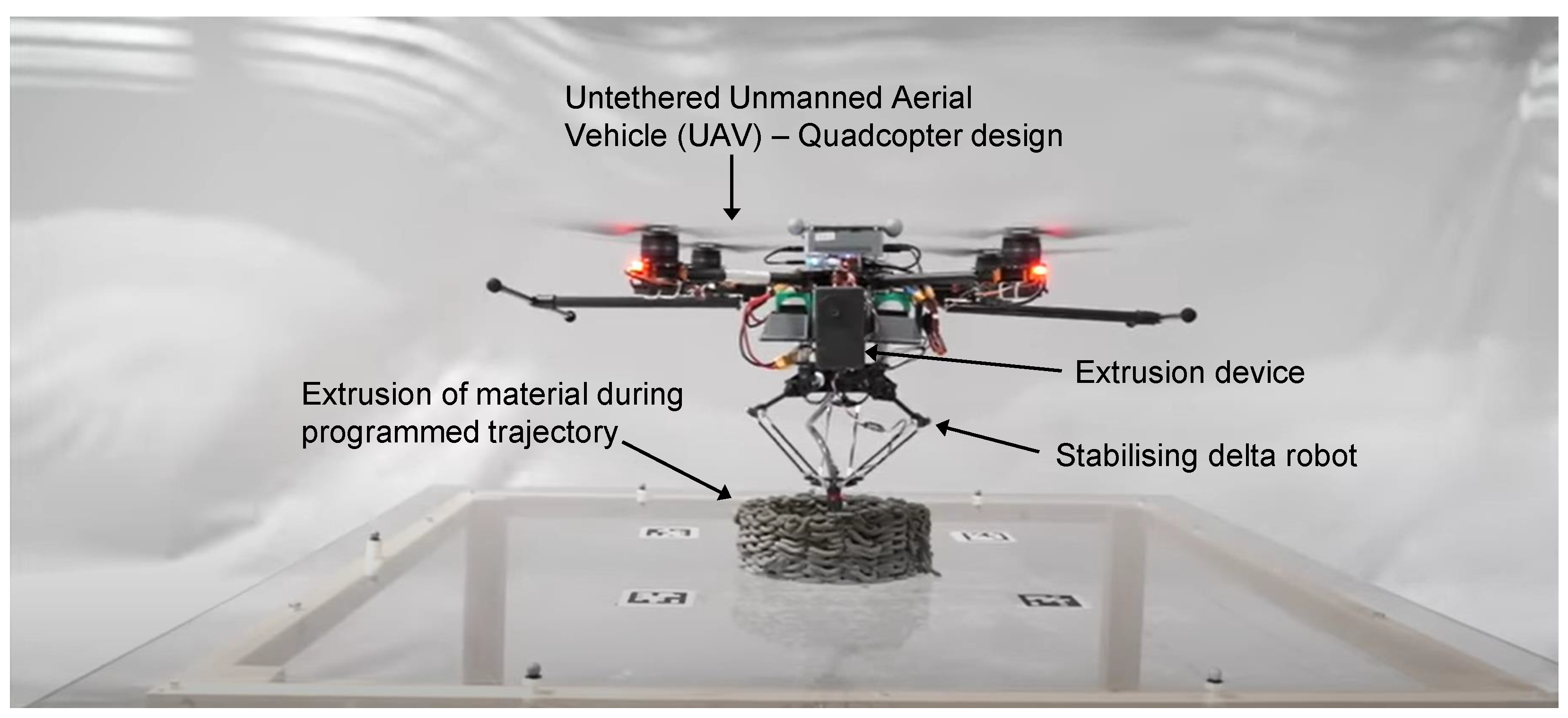
Figure 1 illustrates a programmed, untethered UAV extruding multiple layers of cementitious material in a Peano curve design ‘on the fly’ [
12]. FDM is a suitable principle for AAM and the feasibility of UAVs 3D extrusion-printing other materials in addition to cementitious-based formulas such as polyurethane foam during controlled flight has also been demonstrated [
18].
UAVs have become established in numerous sectors including military, civilian and emergency services [
20]. The use of aerial robots in the construction industry has grown to the extent that the industry is now a leading sector in aerial robotic use [
21]. However, the applications have typically dealt with topographical surveillance, building inspection and data gathering to assist cost estimations [
22], rather than the AM construction or repair of a building in situ. An aerial approach is intended to free AM from ground-based design and logistical constraints, and is designed to be particularly effective in reducing safety risks and costs when confronted by elevated, hostile or inaccessible environments [
12,
19] which present human hazards or topography challenging for ground-based methods. Examples include post-natural, or human-made, disaster reconstruction and working at height on projects such as bridges and stadia, an inherently dangerous task with falls from height causing over a third of construction industry fatalities [
23] and scaffolding related operations being a leading cause of falls [
24].
An alternative miniature syringe-based deposition device, light enough to be carried by an aerial robot and capable of drawing up and extruding high viscosity liquids, has previously been developed for horizontal attachment to the base of a UAV [
19]. This study modifies the miniature deposition device in order to investigate cementitious mortars and pastes suitable for AAM with additional additives and admixtures to assess the impact upon rheological properties.
In addition to layer adhesion, the following parameters have been identified as important for fresh, wet cementitious materials in AM processing: ‘pumpability’ (the ease and consistency at which a material may flow through a deposition device), ‘extrudability’ (the ability of the material to be deposited through a nozzle), ‘open time’ (the duration of time in which material properties remain within the range required for printing, prior to full curing) and ‘buildability’ (a measure of how freshly extruded material can be deposited in layers and resist deformation under loading) [
7]. In the context of AM, buildability may be further defined as a term describing the ability possessed by a freshly deposited filament to both support its own self-weight and support the weight of subsequently deposited layers. Pumpability and extrudability will be dealt with in this study by encompassing the parameters into the general term ‘workability’.
Crucial to the success of a material developed for AM extrusion is the recognition of the trade-off between buildability and workability [
15]. A desirable balance encompassing both qualities in the chosen material is sought. A plasticiser is an important admixture in this respect, allowing a reduction in the water:binder ratio (thus improving strength and buildability), while aiding workability [
13]. Mixes with high workability have lower stiffness and lower initial strength (thus reducing buildability), but encourage greater cohesion between layers by maintaining a chemically active surface longer, promoting inter-facial bonding where properties are closer to bulk material [
9], thus enhancing the durability of the extruded element.
Other previous AM studies using cementitious materials have used mix proportions from which AAM had to differ notably. Ground-based concrete printing studies have used mortar mixes with a sand:binder ratio of up to 3:1 [
13]. It became clear during preliminary mix formulation that such ratios were impractical with a miniature single component deposition method as employed in this study, and 1:1 provided a maximum sand:binder ratio which could facilitate the workability required for successful material transport. Previous studies using high strength cementitious materials have used water:binder ratios below 0.30 [
13,
25]. The XstreeE ‘Democrite’ project used 10% by weight of Silica fume and a low water/(cement + sand) mass ratio of 0.1 [
26]. The mesh mould and Knit Candela projects (which utilises a sprayed concrete approach) were developed at ETH, Zurich, Switzerland; the former has mixes containing a sand:binder ratio of approximately 2.5:1, a water:binder ratio of 0.6 and a mortar density of approximately 2100 kg/m
[
27] while the latter designs for a compressive strength in the concrete of 20 MPa [
28]. Additionally, the 3DCP project developed at TU Eindhoven, The Netherlands, reported densities of 2000 kg/m
[
29] and compressive strengths of 30 MPa [
9], while mix formulation for this study aimed at a compressive strength of 25 MPa and a density towards 2000 kg/m
, it was clear that water:binder ratios below 0.3 would be challenging for the lightweight deposition device to extrude.
This study demonstrates that an accelerator-free, rheologically suitable mortar mix with a suitable open time can be drawn up and deposited in a fresh state by a miniature extrusion system without the requirement for formwork or 3D-printed supporting material. The properties of pastes and mortars immediately following extrusion are critical [
7] and the rigidity of the freshly extruded filament is a primary factor in buildability [
9]. The trade-off between the ability of the mixes to be drawn up and extruded by the deposition device through a nozzle (workability) and the number of layers printed, along with the capability of printed material to resist deformation (buildability), is evaluated in the laboratory using multiple layer extrusion by a robot arm, representing the movement of UAVs in 3D space and quantified with multiple tests. Calorimetry tests assessed how different constituents affected the rate of heat generated during the hydration reactions of fresh mortar mixes. 28-day specimens of the mixes were subjected to compressive, flexural and creep tests to assess how the differing constituents influenced mechanical strength and resistance to long term deformation. Microscopy and X-ray Computer Tomography further visually examine material properties. This study highlights how cementitious material suitable for an aerial approach using the fresh properties and open time of mortar, transported through miniature deposition equipment with light plastic components, contrasts significantly with existing heavy ground-based deposition systems using large metallic components.
2. Materials and Methods
Four mortar mixes and one cement paste mix termed A, B, C, D and E were formulated and manufactured. Workability was defined by the ability of the material to be drawn up and extruded using the deposition device. Electrical power requirements for the deposition device to process the mixes were also monitored. Buildability of the mixes was assessed by the number of layers extruded and the ability of an extruded layer of fresh material to retain form and shape following deposition on to a level, free surface at room temperature without excessive deformation. The mixes were further judged on mechanical properties at 28-day strength.
2.1. The Deposition Device
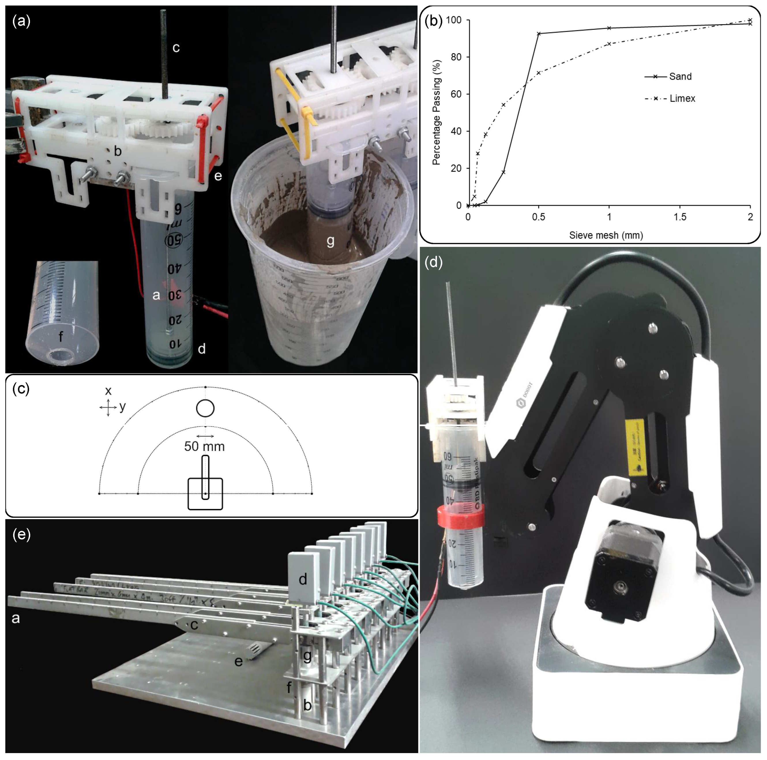
The syringe-based deposition device used in this study is shown in
Figure 2a. A similar dual-syringe device with additional silicon tubing and a static mixer has already demonstrated the feasibility of drawing up and extruding polyurethane foam liquid components for AAM [
19]. For the development of mortar mixes in this study, the deposition device design consists of a single BD Plastipak 60 mL concentric luer lock syringe with a 29.4 mm external diameter barrel.
The device was powered by a PL 155 Aim TTI (Aim and Thurlby Thandar Instruments, Huntingdon, UK) bench supply and had a miniature 6 V DC brushed motor with a 298:1 micro metal gearmotor running gears at 100 revolutions per minute and using 494 Nmm torque. The syringes plunger was actuated by a 3 mm diameter leadscrew, translating the motor shaft’s rotation to linear motion [
19]. The quadcopter UAVs developed for AAM have a carrying capacity in excess of 600 g [
10], therefore the device is certainly light enough to be carried while full of material.
The luer lock was removed from the tip of the syringe and an 8 mm hole drilled in its place to form a nozzle flush with the base of the syringe. The deposition device was kept stationary when drawing up the mortar using a retort stand and clamp. Motor voltage was maintained at 5.95 V, allowing the current to vary during the drawing up and extrusion of mortar. Syringe dimensions and current requirements facilitated the calculation of the varying power requirements of the mixes.
2.2. Cementitious Mix Constituents
The workability and buildability of the fresh mixes were assessed by determining whether it was possible to draw-up and deposit eight cohesive 50 mm diameter circular layers on to a level free surface, without supporting material, during a two hour open-time period. Preliminary tests using a cone penetrometer on cementitious pastes had revealed that workability becomes compromised beyond two hours [
30].
This study used Dragon Alfa CEM I 42.5 R (Dragon Alfa Cements Ltd., Gloucester, UK) Portland cement with a particle size of 5–30 μm and bulk density 900–1500 kg/m
3, as the base binding constituent. The chemical composition of the CEM I, determined by Rietveld quantitative phase analysis, is shown in
Table 1.
The lignin-based plasticiser used was Adoflow ‘S’. Binding additives were Cemex EN 450 N (Cemex, Bristol, UK) grade type-F pulverised fuel ash (PFA), with a bulk density 800–1000 kg/m, particle size: <45 μm, and silica fume supplied in powder form by FerroPem, Anglefort, France with a bulk density of 200 kg/m and mean particle size of 0.2 μm. PFA was added to the cementitious mixes for two reasons; firstly, it has a microstructure of spherical particles which would aid the workability of the mixes, plus as an industrial by-product it would allow the reduction of the use of CEM I in the mixes and therefore help to mitigate the carbon impact of the mixes. Silica fume was added to the mixes with the aim of improving the buildability and the compressive strength, with very fine particles interlocking with the larger particles of the other constituents such as CEM I and sand.
Fine aggregate consisted of angular-particle sand (supplied by Jewsons, Bath, UK, product number AGSTB003), which was kiln dried at a temperature of 105 °C for a period of twenty four hours prior to sieving and possessed a loose dry density of 1600 kg/m
. A further additive investigated was limeX70, which is a by-product of the sugar beet industrial process and is typically used for the correction of soil acidity in the agricultural industry [
31]. The particle size gradation of the sand and limeX70 used is shown in
Figure 2b. To facilitate an extrusion force through the 8 mm diameter of the syringe nozzle within the capacity of the motor, the maximum size of sand particles was 2 mm.
Limex70 consists of 52% calcium carbonate, 15% “organic” composition, 5% silicate, and 30% water [
31]. It has been reported that calcium carbonate has an accelerating effect on the hydration of concrete, which hardens the concrete quicker at the early stage [
32]; the aim of adding this constituent was the investigation of whether it would aid the buildability of the material following deposition and contribute to the cured mechanical properties.
In addition, 12 mm long, 40 μm diameter polypropylene fibres were investigated. Polypropylene fibres were added with the aim of increasing buildability and with a view to mitigate crack propagation and improve the tensile properties of mortars which do not contain traditional steel reinforcement.
A viscous polyol resin, Isothane (Accrington, UK)’s Reprocell 500, ≤2500 cP at 25 °C environment temperature [
19], was added to assess the effectiveness of modifying the rheological properties of the fresh material along with any ensuing impact upon cured mechanical properties. It has been previously determined that a polymer which contains the hydroxyl-terminated side groups can effectively increase the flow retaining behaviours and therefore improve the flow, or workability, of cement [
33].
During the experimentation, the water temperature added to the mixes was 16.5 °C ± 1 °C and laboratory temperatures were 20 °C ± 3 °C.
2.3. Cementitious Mix Specifications and Manufacture
Mix formulation and the workability of ensuing mixes was informed by the capabilities of the miniature extrusion device, which had to be light enough to be carried and powered by a flying UAV.
Mix proportions of the cement paste mix
A and mortar mixes
B–
E formulated for this study are detailed in
Table 2. Mix
D had 1.2 kg/m
3 of polypropylene fibres added. The water:binder ratios used with the mixes were between 0.30 and 0.50. Constituents are shown in kg/m
3 with the total fresh density of the mix indicated, along with the % quantities of admixtures and sand:binder and water:binder ratios.
Mix
A essentially acts as a reference, or control, mix. It is a simple cement paste, which did not contain fine aggregate or additives, and had previously been demonstrated as a material which possessed suitable workability for AAM [
30], but the buildability could be improved upon. Therefore, the performance and characteristics of formulated mortar mixes
B–
E could be compared with respect to their added combination of constituents in relation to mix
A.
The pastes and mortars were created using the following method:
Once weighed, the binder, fine aggregate and additives were hand mixed and transferred to the bowl of an automatic Savisto (Stockton-on-tees, UK) 800 Watt mixing device.
The water, plasticiser and polyol resin (if present) were then weighed, hand mixed and poured into the bowl with an even distribution among the powdered constituents. The mixing device possessed a steel beater revolving in planetary motion.
Slow mixing was administered for an initial ten seconds followed by three thirty second periods of 400 rpm mixing interspersed with manual gathering, thus ensuring the resulting mixes possessed a suitable consistency.
The material was transferred into a 600 mL plastic container and subjected to a further thirty seconds of manual mixing.
Finally, the syringe of the autonomous deposition device was inserted into the material and submerged by 10 mm to draw up the mixes (as shown in
Figure 2a).
2.4. The Robot Arm
The robot arm used in the study to hold and transport the syringe device during autonomous deposition was a Dobot Magician model with four degrees of freedom, a 320 mm reach and a 500 g carrying capacity (close to the 600 g typical capacity of AAM quadcopter UAVs). The syringe device was fixed to the robot arm with a custom designed 3D-printed syringe holder to facilitate unhindered movement of the arm in the X (outwards and inwards), Y (left to right) and Z (vertical) planes as illustrated in
Figure 2c. This also assisted detachment from and reattachment to the robot arm, as the syringes required the refilling of material between layer printing. For each mix, 50 mm diameter circular layers were extruded centrally to the robot arm field of operation. A plan view of the field of operation (within the semi-circular boundaries), and circle as programmed into the Dobot Studio software V1.4.12, is also illustrated in
Figure 2c. The velocity of the robot arm was 2 mm/s. Therefore, a 50 mm diameter layer with a 157 mm circumference could be printed in 78.5 s. The robot arm with deposition device attached is illustrated in
Figure 2d.
2.5. Rheology, Fourier Transform Infrared Spectroscopy (FTIR) and Calorimetry
To assess whether a suitable balance between workability and buildability may be linked to quantifiable rheological data, oscillatory stress tests to determine the Complex modulus G*, elastic-deformation component storage modulus G′ and viscous-flow component loss modulus G″ were carried out on the mortars for two hours immediately following mixing using a TA Instruments DHR-2 rheometer (TA, Hertfordshire, UK). Disposable aluminium smooth parallel plates with a 25 mm diameter upper geometry and 40 mm lower plate were used with a geometry gap of 1000 μm. The displacement-controlled oscillatory tests used a small angular velocity of 5.0 × 10⁻⁵ radians per second, ensuring the material stayed within the linear viscoelastic region. Frequency was kept constant at 1 Hz (an angular frequency of 6.28 radians per second) and a temperature of 25 °C was maintained. The samples tested for each mix consisted of material taken from the same batches created for the workability and buildability tests with the deposition device.
Fourier Transform Infrared Spectroscopy (FTIR) was carried out to identify the functional groups of the polyol resin, with particular emphasis on the purpose of identifying and confirming the presence of hydroxyl groups. The instrument used was a Perkin Elmer Frontier 91175 instrument with a diamond Attenuated Total Reflectance head (Pike Technologies Inc., Madison, WI, USA). The resolution was 2 cm−1 and the wave number parameters ranged between 600 cm–4000 cm.
Calorimetry tests were conducted over a period of 48 h to assess how the differing constituents affected the heat evolution rate of the exothermic hydration reactions of the mixes. 40 g samples of each mix were placed into sealed containers immediately following mixing and inserted into the chambers of a Calmetrix I-Cal 4000 (Calmetrix, Boston, MA, USA) high precision isothermal calorimeter linked with CalCommander v.1.67 software. The temperature of the chambers was maintained at 20 °C. Two samples of each mix were tested, and the mean results were taken.
2.6. Mechanical Tests upon Cured Specimens
To give an indication of the impact of the additives and admixtures upon 28-day strength, compressive and flexural tests were conducted using a 200 kN servo-hydraulic testing rig model DH 200 (Mayes, UK) hydraulic test frame with Instron WaveMatrix software. Three prismatic shaped test specimens 160 mm long × 40 mm wide × 40 mm high for each of the five mix designs were formed in steel moulds lubricated with mineral oil, thus providing three flexural strength test specimens and six compressive strength test specimens (broken half-prisms) for each mix. Specimens were cured in a controlled environment for 28 days at a temperature of 20 °C and 55% relative humidity prior to testing in accordance with the British standard BS EN 1015-11:1999 [
34].
Deformation due to long term loading was evaluated over a period of 50 days using 18 mm diameter, 37 mm high cylindrical specimens of material. The specimens were placed into a bespoke rig as shown in
Figure 2e, where a predetermined load was evenly distributed over the full cross-sectional area of the cylinders. The rig was equipped with eight Solartron LE12 linear displacement transducers, capable of reading to an accuracy of 50 nm. Together with a USBIM Mk2 (Solartron, West Sussex, UK) controller, the transducers formed an Orbit 3 network powered by a Solartron PIM supplementary supply. Weights of 1 kg were suspended from the lever arms yielding a mechanical advantage of 18. Displacement, temperature and humidity readings were taken concurrently at five-minute intervals to assess the varying deformation and the impact of environmental changes upon the specimens.
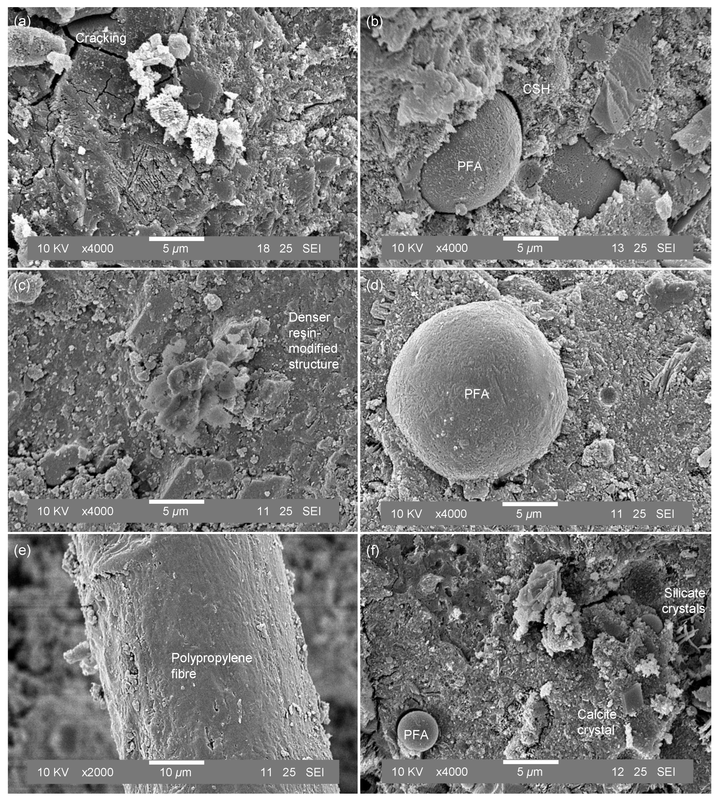
2.7. Scanning Electron Microscopy
A JEOL 247 SEM6480LV (JEOL, Hertfordshire, UK) scanning electron microscope (SEM) was used to obtain images of cured sample specimens of mixes SEM images of cross-sectional morphology of mixes A–E at magnifications of ×4000 and ×2000 to qualitatively assess sample microstructure. The specimens were covered with a 10 nm gold coating immediately prior to insertion into the SEM chamber in order to reduce charging.
2.8. X-ray Computer Tomography
X-ray Computer Tomography (CT) scans were applied to investigate the 3D structure of the circular layers of the extruded mixes. The CT scans were measured using a Nikon XT H 225 ST model machine (Nikon Metrology, Leuven, Belgium) and conducted using 65 kV and 50 A X-ray beam output. The obtained data files were subsequently analysed by using VGStudioMAX (Volume Graphics, Hexagon, UK) software.
Figure 2.
Experimental Methodology illustrations. (a) The miniature deposition device, kept stationary with a retort stand and clamp. a, 60 mL syringe. b, 6 V DC brushed motor. c, 3 mm diameter leadscrew. d, plunger. e, constraining tie cables. f, 8 mm diameter nozzle drilled into the syringe base. g, cement paste being drawn up by the device. (b) Particle size gradation of the sand used as fine aggregate and limeX70. (c) Plan view schematic diagram of the field of robot arm operation showing placement of the 50 mm diameter circular layer depositions. (d) Dobot Magician robot arm with attached syringe deposition device. (e) The creep rig with cylindrical mortar samples a, 1 kg weights suspended from this location. b, Cylindrical samples of mixes A–E. c, Lever arms. d, Solar orbit linear encoders. e, Temperature and relative humidity sensor. f, Circular platens. g, Pivots.
4. Discussion
The study highlights the trade-off between workability and buildability along with the impact these parameters have upon quantitative material properties. This study suggests that the correct approach to take is to accept the trade-off between workability and buildability and acknowledge that there will be a challenge in one of those parameters for a higher strength material.
It is reasoned that the addition of silica fume to mix
D, along with the use of sand and fibres, contributed to the requirement for increasing the water:binder ratio from 0.33 to enable an extent of extrusion from the deposition device (
Figure 8). It is further reasoned that the higher water:binder ratio contained in mix
E was necessitated by a combination of the addition of silica fume and limeX70 in order to facilitate material extrusion. The addition of polyol resin in Mix
C facilitated an increase in the sand:binder ratio and the addition of Silica fume without compromising workability. With mix
B, it is submitted that the lower water:binder made the difference in the mix being challenging to extrude and requiring higher power, whereas Mix
A was too workable in the fresh state and inherently contained a high carbon footprint regarding CEM I content.
Table 4 confirms that it is possible for a mix to perform well in workability at the expense of buildability and vice versa. Where the mixes perform well in both parameters and possess a suitable workability-buildability balance, this also may come at a cost. Mix
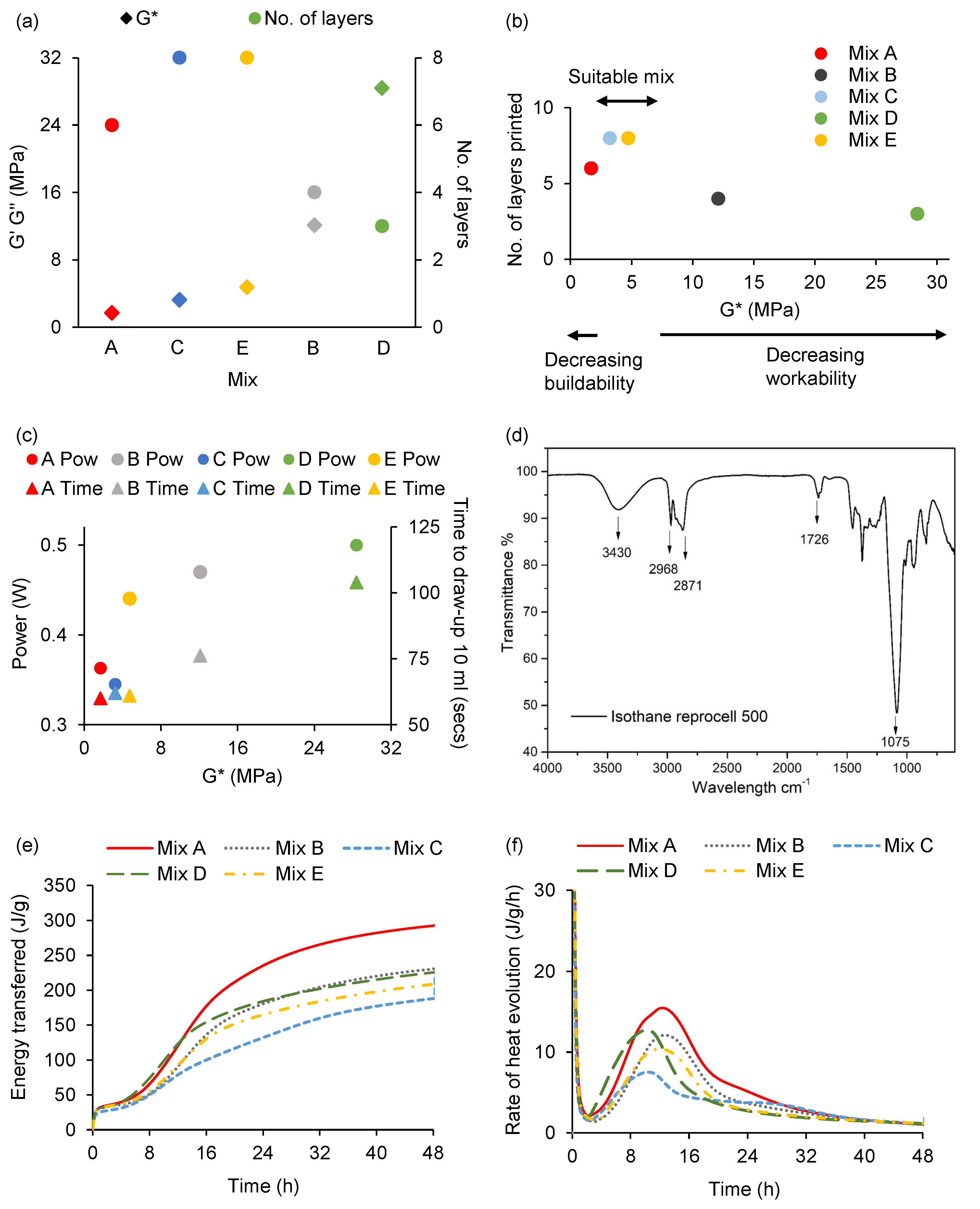
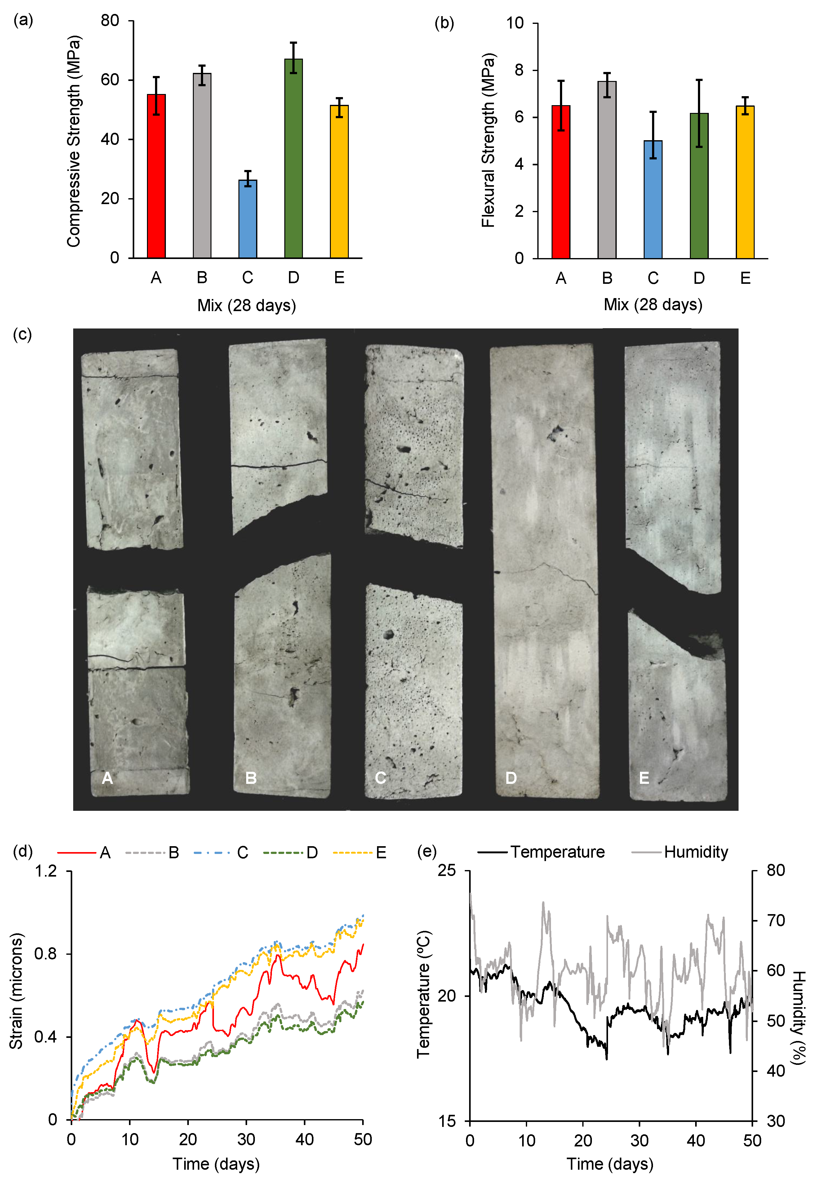
C was highly workable and held its form well, being able to receive multiple layers. However, as shown in the calorimetry results (
Figure 4), the addition of the rheological modifying polyol resin retards the C-S-H reaction during hydration of the mortar mix. C-S-H is an important contributor to the binding properties [
40] and reaction inhibition reduces compressive strength.
Mix
E also performed well in both workability and buildability – again at a cost, as adding limeX70 to the mix required a significant increase in water:binder ratio to make the mix workable, thus inevitably impacting compressive strength. Highly workable mixes
C and
E additionally displayed the highest deformation during long term loading (
Figure 5).
While a pure cement paste is certainly workable for the miniature deposition device, it was clear that the addition of fine aggregate promotes the successful printing of multiple layers, as mix
A deformed irreparably during the layer extrusion process. With fine aggregate, mixes
B–
E did not exhibit this deformation. A further purpose of the additional binding materials and fine aggregate is to reduce the level of Portland cement used in the mixes, as an entirely cementitious paste is not favourable when considering sustainability. Portland cement has long been established as a material with an undesirably high carbon footprint, with the raw materials requiring burning at high kiln temperatures of 1400–1500 °C [
37]. The addition of industrial by-products (PFA, silica fume, limeX70) as additives mitigates the higher embodied carbon of the mortar mixes, which is a current characteristic of AM cement slurries, though this can be offset by geometric optimisation of printed elements [
17].
It is suggested that workability, defined in this study as the ability of a material to be processed by the deposition device, is the primary qualitative material parameter for the relative miniaturisation of AM required for aerial applications. There should therefore be less of an emphasis on attempting to achieve very high compressive strengths through using very low water:binder ratios, with the miniature deposition system requiring water:binder ratios approaching a more conventional level for concrete at ≈0.50. It is reasoned that if a formulated mix cannot be processed autonomously in a lightweight device with aerial robot portability, high compressive strength is essentially immaterial. A further driver in considering workability to be the prime parameter is the mitigation of power used in the processing of the material, with a more workable, rheologically suitable mix using less energy and requiring less time to process.
While the polypropylene fibres used in mix D presented a challenge with regards to workability, the ability of the fibres to partially hold a failed specimen together can be identified as a potential performance asset in a mortar mix without reinforcement. The use of fibres of a suitable length and dimensions would form part of a further investigation concerning the introduction of a measure of ductility within the material, mitigating the sudden, brittle nature of failure and reduce the level of shrinkage and crack propagation. Mix D performed well in both compressive and flexural tests and there is capacity within the mix to further increase plasticiser content and water:binder ratio to address the challenge of workability posed by the presence of fibres.
With mix
E having a water:binder ratio approaching 0.50, the use of limeX70 would require an alternative approach to mitigate negative impact upon strength. This study used quantities of plasticiser of 1–1.5% by weight of binder and the compressive strength results suggest that an approach of further increasing plasticiser content up to 2% by weight of binder should be investigated when using limeX70 and fibres, thus maintaining required workability. Regarding limex70, the calorimetry test results in this study showed an opposite result to that initially expected. In fact, Mix E has a low hydration rate, even lower than that of Mix A (as seen in
Figure 4). The possible reason could be due to the quantity of organic composition within limeX70, which contains compounds including carbohydrates, proteins, plant fibres and alcohols. The effects of polysaccharides and saccharides on the hydration of cement have been previously investigated and it was discovered they have a retarding effect on cement hydration and the formation of both C-S-H and portlandite could be slowed and delayed [
41,
42]. In addition, the proteins can be treated as a retarder in cement (whey protein cement retarder). Therefore, despite the modest organic content of limex70 (15%), this quantity is evidently sufficient to dominate the hydration of Mix
E. Limex70 can act as a substitute of CEM1 for the mitigation of the carbon footprint of the material, but it appears to cause the retardation of cement hydration, which is a consideration for AM processes. Further work could focus on controlled variance of quantities of limeX70 in AAM mixes to assess combinations of workability and buildability, and effects upon hydration.
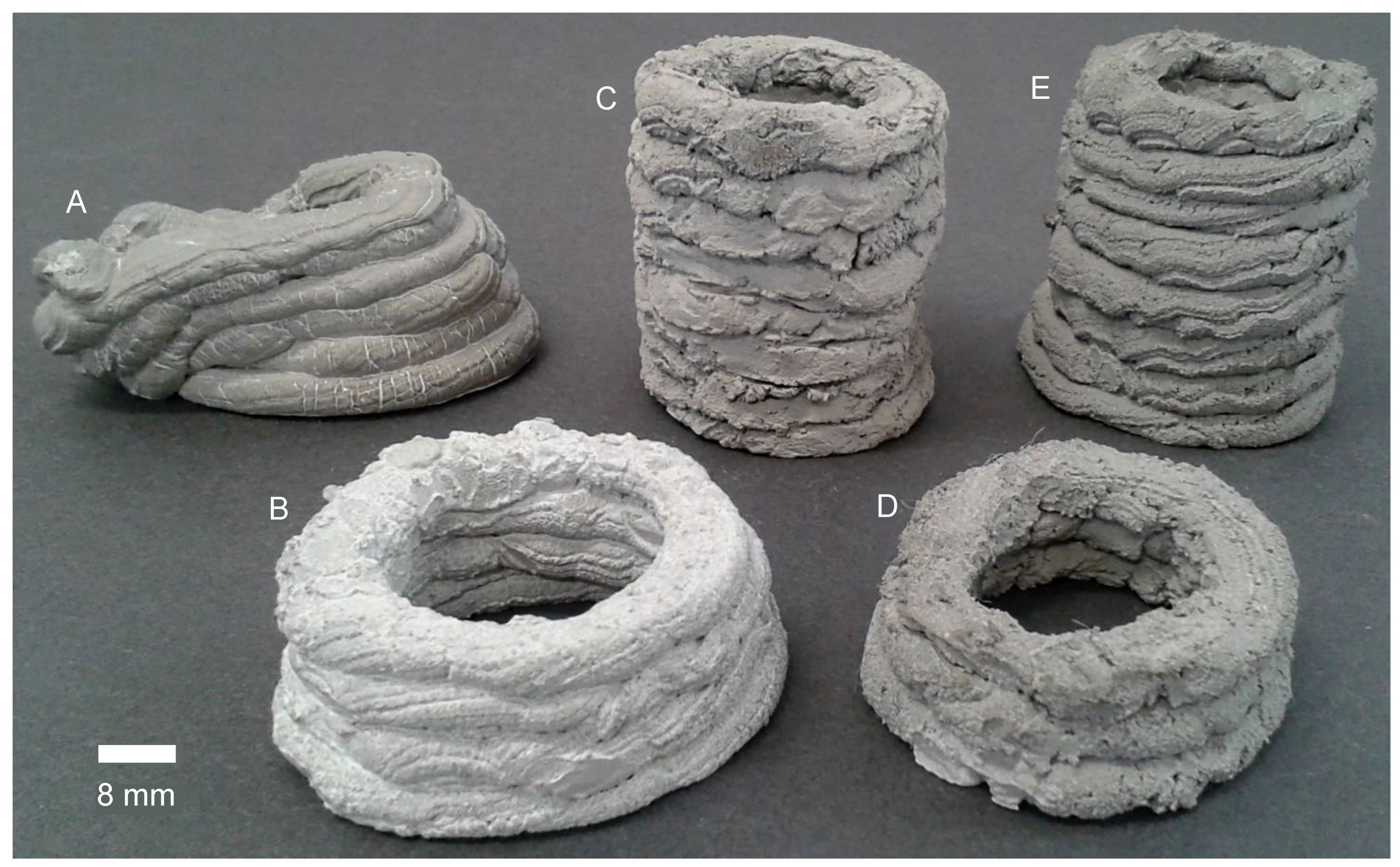
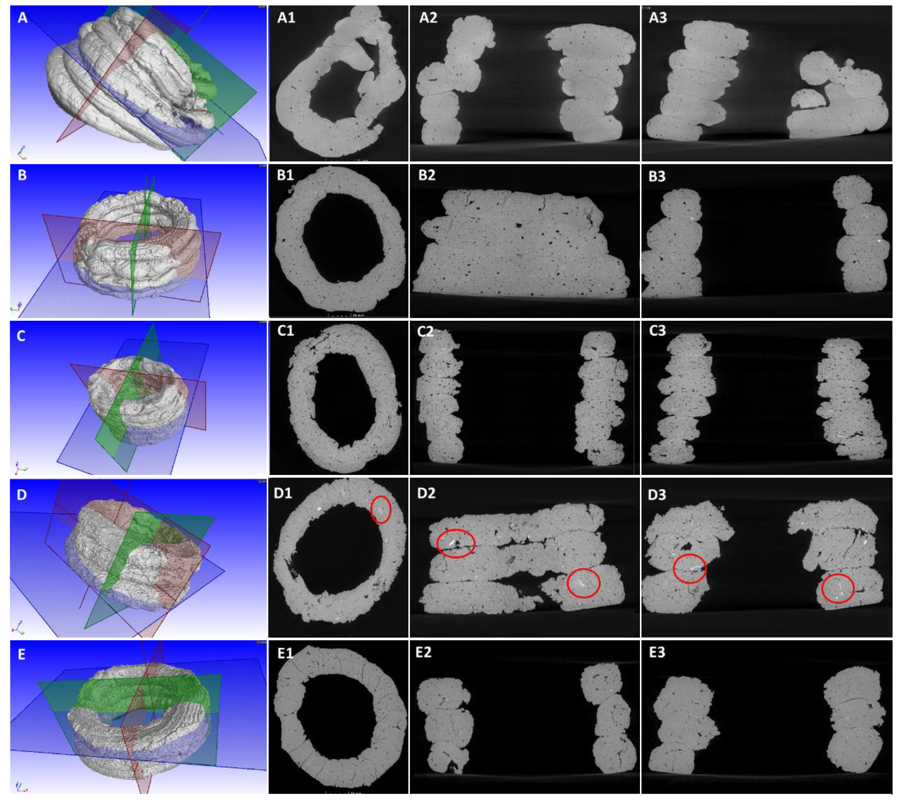
As shown in
Figure 7A1–A3, the distorted structure means that cement paste could not maintain the circular shape, which suggests Mix
A has poor buildability. The circular structure can be maintained with the introduction of fine aggregate (
Figure 7B1–B3). The addition of polyol resin improved workability and did not impact negatively upon buildability (but did upon strength). The circular structure made by Mix
C can be maintained as high as 6 layers (
Figure 7C1–C3). In terms of Mix
D, the presence of polypropylene fibres can be identified from
Figure 7D1–D3), where the red circles marked areas show that the white-colour fibres were randomly distributed through the structure. In addition, more pores and layer-boundary gaps can be found in Mix
D, suggesting that the addition of fibres can present a challenge for workability. Regarding to Mix
E (
Figure 7E1–E3), its structure is similar to that of Mix
B and Mix
C, the addition of limeX70 can help to maintain the circular structure, with an improved buildability.
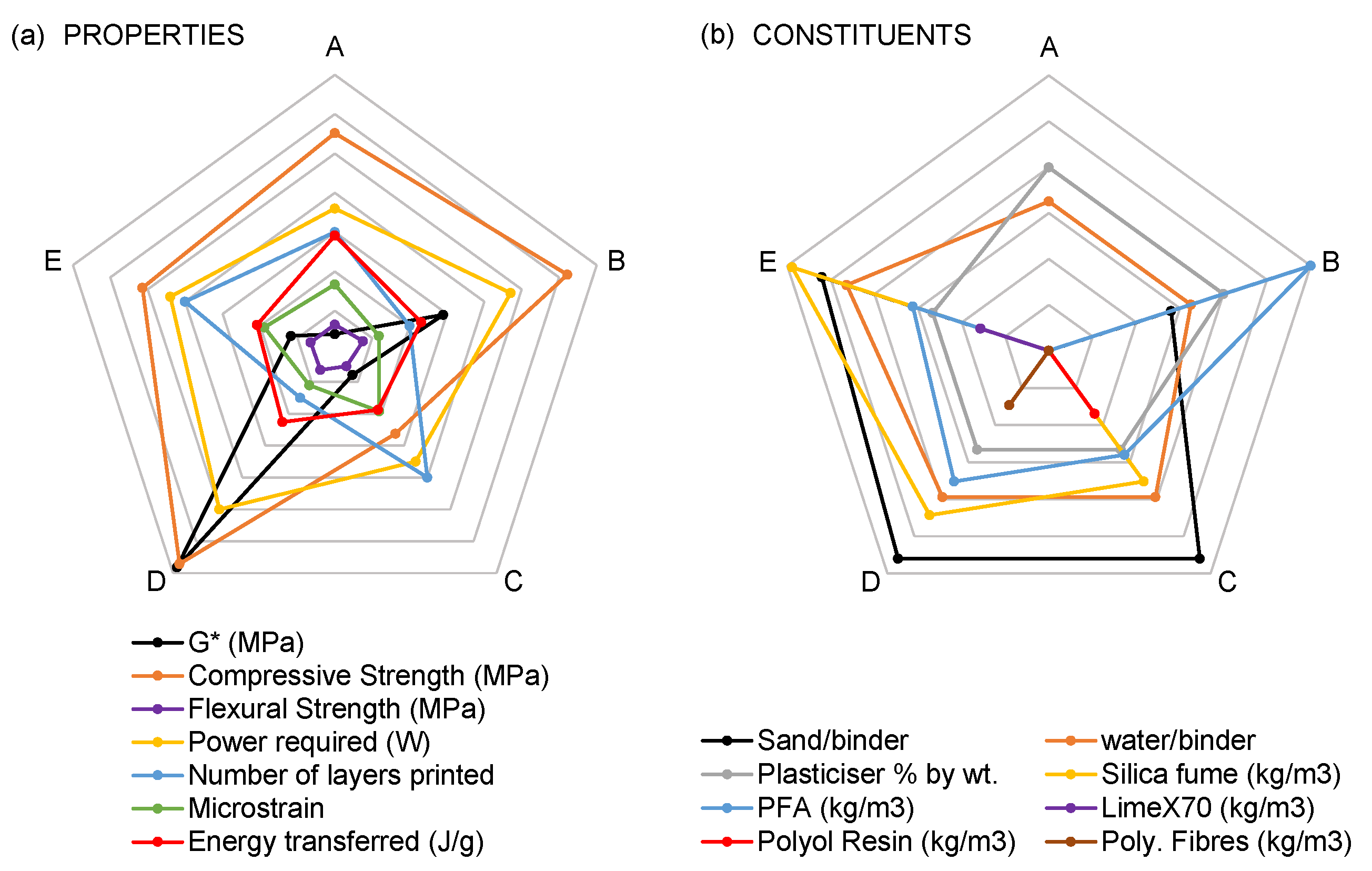
The study shows that the Complex modulus
G* of the mixes, which measures the rigidity of the mortar’s soft-solid structure, can serve as quantification of the workability-buildability balance contained within the mix and indicate whether the mix is suitable for AAM extrusion. The most rigid mixes
B and
D were the most challenging to process and the least rigid mixes
A and
C were the most workable.
Figure 4 quantifies
G* values of 3–6 MPa as a good balance between workability and buildability for AAM. Below this value and the material is lacking in rigidity, possessing good workability but inadequate buildability, as shown in this study with the lateral deformation of mix
A. Above 6 MPa and the material becomes too rigid for the device used in this study, with buildability dominating to the detriment of workability, as demonstrated by the device having difficulty processing mixes
B and
D.
A previous AAM study using liquid components of polyurethane foam with a dual-syringe deposition device employed a 986:1 gearing ratio motor [
19]. The change in this study to a faster, lower torque 298:1 micro metal gearmotor was informed by both the desire to increase velocity and the realisation during this study’s preliminary tests that higher torque promoted segregation of mortar constituents. This results in material disproportionately high in water content being extruded and the forming of dead zones of compacted aggregate and additives around the internal sides of the syringe’s tapered end. The requirement for higher velocity and lower torque emphasises the importance of the workability of the mixes, as a lightweight deposition device will need to process the mixes using minimum torque in order to decrease constituent segregation, increase the rate of deposition and place minimal demand on the power source of a UAV host during controlled flight.
Mix
C possessed a good combination of workability and buildability and while possessing the lowest compressive strength, remains structurally viable. Alternative RMAs can further be investigated for AAM, and indeed it has been shown that Cellulose gum and Xanthan gum are suitable options for AAM [
12]. Using RMAs also reduces constituent segregation.
A further consideration for all AM cementitious extrusion is post-extrusion alignment and potential deformation of the filament. Material deformation may be due to the inherent effects of gravity, the weight of subsequent layers compressing previously extruded layers, material shrinkage effects or geometrical variations in filament dimension or the trajectories of the automated deposition device, while mixes
B–
E did not significantly deform in the manner of cement paste mix
A, imperfections in the extruded filaments may be observed in
Figure 7, notably mix
D which was the ‘driest’ of the formulated mixes and it was challenging to extrude a filament of entirely consistent dimensions. Any slight variation in alignment of extrusion may result in imperfections in height and width of the extruded filament. Development of a test method to quantify extruded material deformation would be a further asset in evaluating the precision and stability of height of extruded AM material. Buildability and excessive rigidity may be considered further as to whether denser material post-extrusion can be printed to a number of geometrically cohesive layers, while the rigidity of mixes
B and
D suggest buildability appropriate for a larger deposition device requiring more power, it may be submitted that the buildability of the mixes themselves cannot be entirely judged unless the deposition device can print further layers - but it can be judged by this study that the mixes are less appropriate for AAM.
While AAM material with the formulated mixes has been demonstrated, the issue of upscaling an AAM construction operation would require the continued research of UAVs being able to increase their carrying capacity (or ‘payload’) and power delivery capabilities from on-board batteries, which would facilitate larger and heavier extrusion systems. This would combine with the utilisation of a coordinated building approach inspired by natural builders such as birds, wasps and termites, where multiple units work together to build an object - with each unit being aware not only of their own trajectory but the trajectory of other units and an awareness of where other units have already extruded material. Multiple UAV unit extrusion has been demonstrated in [
12] and a coordinated ‘swarm’ of flying, self-powered UAVs is envisaged for a full construction-scale project.
A dome-shaped structure or cylindrical, tapering tower featuring layers of extruded circular filaments would be viable structural and architectural options for AAM using mortar. This study used a circular nozzle primarily due to the end of the robotic arm being unable to rotate about its own axis, therefore a non-circular bead would vary in diameter as the arm progressed in circular motion.
Durability Considerations for AAM
An alternative approach for an aerial robot capable of rotation in controlled flight would be to change the geometry of the nozzle to rectangular. This would achieve greater bead width, increase the bonding surface area between layers thus promoting layer adhesion, bring increased lateral stability to multiple extruded layers and help mitigate adhesion and alignment-related issues of different layers compromising the durability of the extruded cementitious material. It was observed in
Figure 7 that contour imprecision negligible to the naked eye can result in imperfections in layer adhesion; indeed, geometry and shape accuracy have been recognised as a primary issue for AM on a construction scale [
43].
Further considerations for durability is the choice of any reinforcing fibres, whether in continuous filament, placed element or chopped fibre form, included as part of the cementitious material. Fibres increase durability of mixes [
17]; major considerations include suitability within alkaline cementitious matrices and the ability to mitigate crack-propagation within the material. In this study, polypropylene fibres were used due to the compatibility of the fibres within cement mixes, effectiveness in mitigating micro and macro crack propagation [
44] and the addition of fibres resulting in mitigating the potential penetration of water or harmful ions into concrete matrices [
45]. Polyvinyl Alcohol (PVA) fibres are a further option to investigate for AAM with previous studies suggesting durability of the fibres within cementitious matrices [
46] so that concrete with PVA can be considered an engineered, high-performance material [
47].
Additionally, the wider effects of additives and admixtures introduced for the purposes of rheological properties influencing workability and buildability require wider consideration for durability. Added RMAs would benefit from further examination to ascertain any reduction in mechanical properties or performance, sorptivity, or the promotion of shrinkage and resulting micro-cracking of the extruded material and therefore detrimental impact upon long-term durability.


