Article

A Coupled Darcy-Forchheimer Flow Model in Fractured Porous Media

1
State Key Laboratory of Geomechanics and Geotechnical Engineering, Institute of Rock and Soil Mechanics, Chinese Academy of Sciences, Wuhan 430071, China
2
School of Civil Engineering, Wuhan University, Wuhan 430072, China
3
Shanxi Provincial Key Laboratory of Highway, Bridge and Tunnel, Changan University, Xi’an 710064, China
4
Department of Civil Engineering, Sichuan College of Architectural Technology, Deyang 618000, China
5
School of Earth Sciences and Engineering, Hohai University, Nanjing 210098, China
6
College of Civil Engineering, Qilu Institute of Technology, Jinan 250200, China
7
School of Civil and Resource Engineering, China University of Science and Technology Beijing, Beijing 100083, China
*
Authors to whom correspondence should be addressed.
Appl. Sci. 2023, 13(1), 344; https://doi.org/10.3390/app13010344
Submission received: 19 November 2022 / Revised: 14 December 2022 / Accepted: 20 December 2022 / Published: 27 December 2022
(This article belongs to the Topic Complex Rock Mechanics Problems and Solutions)

Abstract

:
Aiming at nonlinear flow in fractured porous media, based on the finite volume method, the discrete equations of Darcy flow in porous and Forchheimer flow in fracture were derived, and a solution method for coupling flow is proposed. The flow solution by the proposed method for single fracture and intersecting fracture is verified against Frih’s solution. Based on this method, nonlinear flow behavior for fractured rock deep-buried tunnels under high water heads was discussed. The results show that the hydraulic gradient of surrounding rock is characterized by “large at the bottom and small at the top”, with a maximum difference of 2.5 times. Therefore, the flow rate at the bottom of the tunnel is greater than that at the top. The fracture flow rate along the flow direction is also greater than that in the vertical flow direction, with a maximum difference of 60 times. The distribution homogeneity and density of fracture are the most important factors that affect the hydraulic behavior of fractured rock tunnels. The more fractures concentrated in the direction of water pressure and the greater the density, the greater the surrounding rock conductivity and the greater the flow rate of the tunnel. Under this condition, the water-inflow accident of the tunnel would be prone to occur. The research results provide a reference for the waterproof design and engineering practice of fractured rock tunnels.

1. Introduction

Seepage in the rock mass is one of the cores of rock mechanics, involving tunneling, mining, petroleum, hydropower, geothermal exploitation, and other projects [1,2,3]. On the one hand, the high permeability of rock fracture leads to a higher fluid flow rate in the fracture compared with the flow in the rock matrix [4,5]. On the other hand, rock permeability is low, and a fluid will pass slowly through the matrix in a rock mass. A complex coupling process for fluid flow exists in fracture and matrix. Therefore, it is still challenging to establish an effective seepage model for rock mass. Since the 1970s, various seepage models of rock mass have been proposed based on the understanding of fracture characteristics and distribution [6,7,8].
The continuum media model is applicable to model fluid flow in a rock mass with a large number of small and regular distribution fractures [9,10]. Based on the homogeneity theory, seepage coefficient tensor theory, generalized Darcy’s law, and the fluid continuity equation, the partial differential equations of flow and pressure are derived. The partial differential equations are solved by the initial conditions and the boundary, and the velocity and pressure fields of the whole flow field are obtained. However, when there are masses of faults or fractures in the study area, the rationality of using the equivalent continuum model remains to be discussed. The discrete fracture network model only considers the seepage of macroscopic fractures in the rock mass, which are usually generated randomly according to their occurrence, size, and hydrological parameters [11]. The governing equation is established based on the flow balance principle at the intersection of each fracture, and then the matrix equation of pressure and flow is obtained by combining the flow equation of a single fracture. Finally, the velocity field and pressure field are obtained by solving the equations. The discrete fracture network model is suitable for large-scale fractures with sparse distribution in the rock mass. However, it does not consider the flow condition of the rock block, and the error may be larger in some high-porosity rock masses. The dual medium model divides fractured rock mass into a porous system and a fractured system [12,13]. It is assumed that water flows on the porous system and the porous system is used to store fluid. The two flow systems exchange on the fracture wall, which satisfies the conservation law of flow. The generalized model holds that the interconnected fracture is the channel of fluid flow, while the pore and the isolated fracture are the stores of fluid. The flow exchange between the two on the interconnected fracture wall satisfies the law of flow conservation. Therefore, the dual medium model can describe the preferential flow phenomenon. At the same time, the exchange effect of water flow is taken into account, which makes the simulation have better accuracy.
In the early days, dual media models assumed that fluid flow in fractured or porous media would conform to Darcy’s law. Darcy’s Law is consistent with a single-phase incompressible flow in porous media at low flow rates, such as water-bearing reservoirs in an underground rock mass with low permeability. However, Darcy’s Law does not apply to wells or high permeability fracture areas where flow rates are higher. To describe the seepage law at high flow rates, one of the simplest ways is to add a second amendment term in Darcy’s Law, which has been widely adopted as Forchheimer’s Law. The law combines the viscous effect and the inertia effect: At low flow, the viscous effect dominates, and the model is simplified to Darcy’s law. When the flow rate is increased, the inertia effect is dominant, which makes the pressure increase nonlinearly with the flow rate. Huang and Ayoub (2008) [14] and Barree and Conway (2004) [15] proved that Forchheimer’s law for laminar flow is effective in a certain range. Chen et al. (2001) [16] and Giorgi et al. (1997) [17] derived Forchheimer’s Law from the theoretical perspective through the homogeneous and perturbation methods, respectively, and proved its existence and uniqueness. Numerically, Douglas et al. (1993) [18] and Xu et al. (2017) [19] obtained the approximate solution of seepage by using different methods, such as the finite difference method and the multipoint flux approximation method. The forms of those solutions are consistent with Forchheimer’s law.
For Darcy flows in the fractures and pores of the rock, the main difficulty of the dual media simulation method is the coupling problem between n-dimensional (n = 2, 3) pore media flows and n − 1-dimensional fractures [20,21,22]. In recent years, many scholars have conducted in-depth studies on this problem. For example, Lang et al. (2014) [23] proposed a calculation method for the total permeability tensor of fracture–pore dual media based on the dual media theory. However, there are few reports on a Forchheimer flow simulation with dual media seepage considering fractures under high permeability pressure. The main difficulty of this problem lies in solving the nonlinear system after fracture discretization. Among them, Fri et al. (2008) [24] adopted the interface model to deal with fractures, added nonlinear transfer conditions to the contact, and simplified the problem into a nonlinear system problem of (n − 1)-dimension by using region decomposition technology. Arrears et al. (2019) [25] adopted the multi-grid method to calculate the nonlinear system problem and discussed the robustness of the nonlinear system for the dual media Darcy–Forchheimer flow. The results showed that the algorithm was heavily dependent on mesh size and the Forchheimer coefficient. So far, there is still no good method to solve the double medium Darcy–Forchheimer flow problem [26,27].
During the long-term operation of tunnels under high water heads, water gushing is a commonly existing engineering geological disaster that needs to be highly paid attention to [28]. The Darcy flow is usually used to analyze seepage conditions in the tunnel rock mass. However, under a high water head, the Darcy flow would result in a large deviation from the field test [29]. Therefore, it is necessary to analyze the seepage field of the tunnel surrounding the rock by using the Darcy–Forchheimer coupled flow method in the fractured rock mass.
Thus, based on previous studies, a Darcy–Forchheimer coupled flow method in the fractured rock mass is proposed based on the finite volume method, taking into account the Forchheimer flow in fractured media and the Darcy–Forchheimer coupled flow in porous media. Based on this method, the nonlinear seepage law of the tunnel surrounding rock is studied, which provides some theoretical and technical support for the waterproofing design of a fractured tunnel.

2. Materials and Methods

2.1. Seepage Equations in the Rock Matrix

The seepage velocity of groundwater in the homogeneous rock matrix is slow and follows Darcy’s flow law. Assuming that the fluid is incompressible, the mass and momentum conservation equations of the fluid flowing in the matrix are [30],
u m = k m μ p m
u m = q m
where um is flow velocity in the rock matrix, km is the permeability coefficient of the rock matrix, μ is the viscosity coefficient of fluid, pm is the fluid pressure of the rock matrix, and qm is the fluid source of the rock matrix.

2.2. Seepage Equations in Fracture

Under a high hydraulic gradient, groundwater flows faster in fractures, which can be described by Forchheimer’s law. The relationships between the pressure gradient and the flow velocity of the fluid in the fracture are as follows [30],
( 1 + β | u f | ) u f = k f μ p f
u f = q f
where uf is flow velocity in the rock fracture, kf is the permeability coefficient of the rock fracture, pf is the fluid pressure of the rock fracture, qf is the fluid source of the rock fracture, and β is the Forchheimer coefficient.
To consider the flow exchange of the porous media and the fractured media, the exchange function Ψ is introduced to show their mutual effect. The strength of flow exchange between porous media and fractured media is related to fluid characteristics and fracture connectivity. Therefore, the exchange function of pressure can be defined as follows:
Ψ f m = C I × k m μ × p f p m L
Ψ f m = C I × k f μ × p m p f A
where CI is the connectivity of the fractures, and L and A are the area (length) of the fracture and the volume (area) of the pore, respectively. Connectivity CI was defined by [31] and expressed as,
C I i j , k = A i j , k d ¯ i j , k
where Aij,k is the total length of fracture k in pore matrix element ij, and the average distance between fracture element k and pore matrix element ij, as shown in Figure 1.
C I i j , k = A i j , k d ¯ i j , k
d ¯ i j , k = l k d A A i j
By expanding this formula, the double integral expression is obtained,
d ¯ i j , k = x x k o 2 + y y k o 2 d x d y d x d y
where, (xko, yko) is the central coordinate of fracture element k in the local coordinate system. Equation (10) generally has analytical expressions in a small part of cases, while most cases must be solved by numerical method. Hajibeygi et al. (2011) [31] gave analytic expressions in some cases.
By substituting the pressure exchange function into Equations (1)–(4), the governing equations of pore and fracture seepage can be obtained,
q m + ( k m μ p m ) + Ψ m f = 0
k f μ p f + ( 1 + β | u f | ) q f + Ψ f m = 0
Equations (11) and (12) describe Darcy flow in porous media and Forchheimer flow in fractured media under high water pressure. The relations to two flows use the pressure exchange function.

3. Numerical Solutions

3.1. Discrete Scheme Using Finite Volume Method

3.1.1. Discrete Scheme of Seepage Equation in Porous Media

The porous media zone Ω was discretized into the quadrilateral element Ωij, as shown in Figure 1. Integrating the porous media seepage equation using the Gauss theory, the volume fraction of Equation (11) can be converted into the surface integral perpendicular to the external surface [30],
Ω i j ( q m + ( k m μ p m ) + Ψ m f ) d V Ω i j ( k m μ p m + Ψ m f ) n d s + Ω i j q m d V
Using the finite volume method, the central difference discrete form of the Ωij seepage equation for each element is obtained,
Δ y k μ i , j m Δ x p i , j m p i 1 , j m + Δ y k μ i , j m Δ x p i , j m p i + 1 , j m + Δ x k μ i , j m Δ y p i , j m p i , j 1 m + Δ x k μ i , j m Δ y p i , j m p i , j + 1 m + q i j m Δ x Δ y + Ω i j Ω k C I k k μ i j , k ( p k f p i j m ) = 0

3.1.2. Discrete Scheme of Seepage Equation in Fracture

Similarly, one-dimensional elements were used to discretize fractures to obtain the central difference discretization form of seepage Equation (12) of each element as follows:
b k k μ k f Δ x f p k f p k 1 f + b k k μ k f Δ x f p k f p k + 1 f + 1 + β u f q i j m b Δ x f Ω i j Ω k C I k k μ i j , k ( p k f p i j m ) = 0

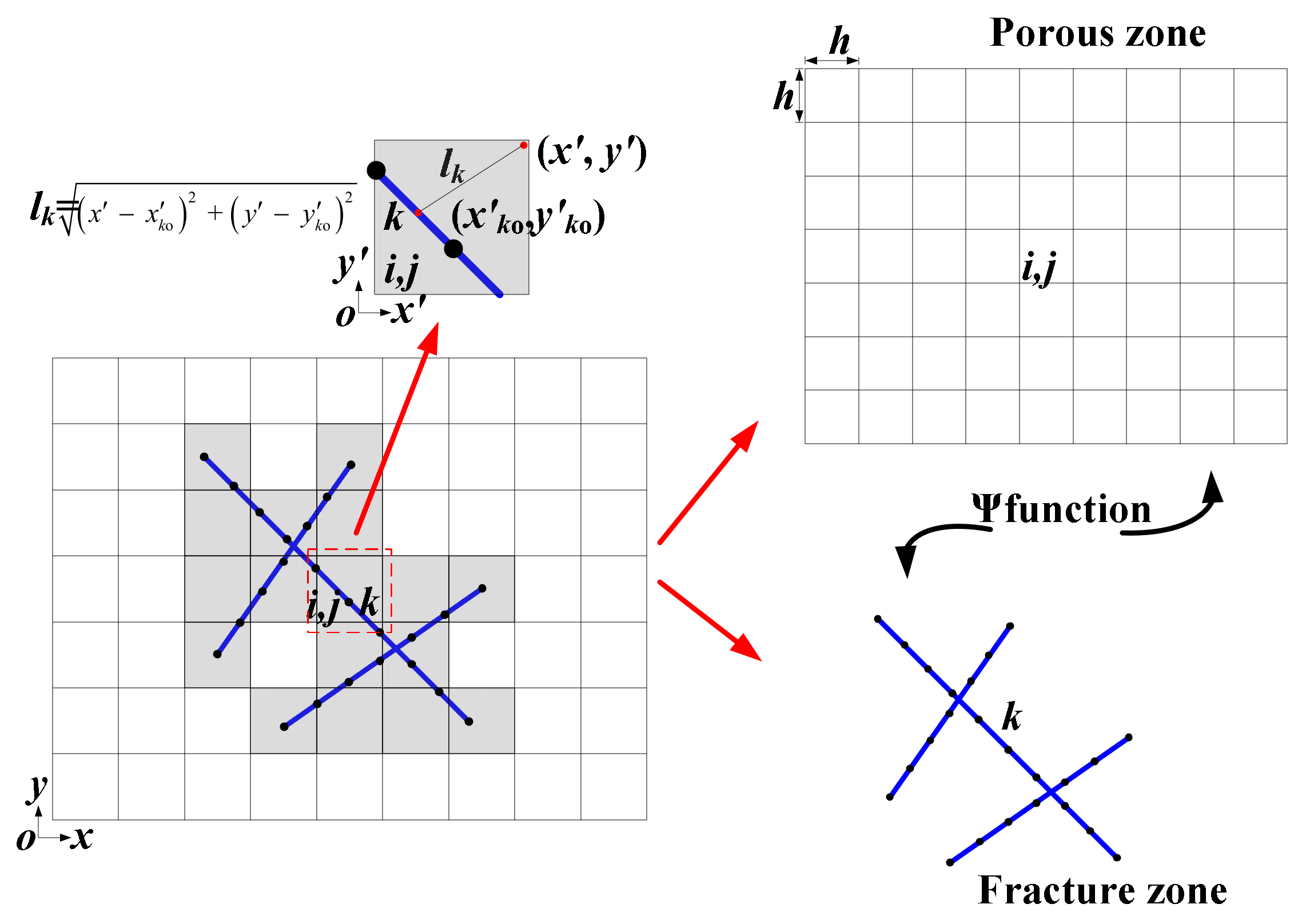
3.2. Treatment of Intersecting Fracture

When the fluid passes through the intersecting fracture, it will lead to fluid head loss and affect the seepage behavior of the whole area. To consider the impact of intersecting fractures on the water head, Karimi et al. (2004) [32] calculated the conductivity Tij of two intersecting fractures (i and j) using the following formula:
T i j = U i × U j U i + U j
U i = k f i μ b i 0 . 5 Δ x f , U j = k f i μ b j 0 . 5 Δ x f
where Δxf is the length of the element, and bi and bj are the apertures of i element and j element, respectively.

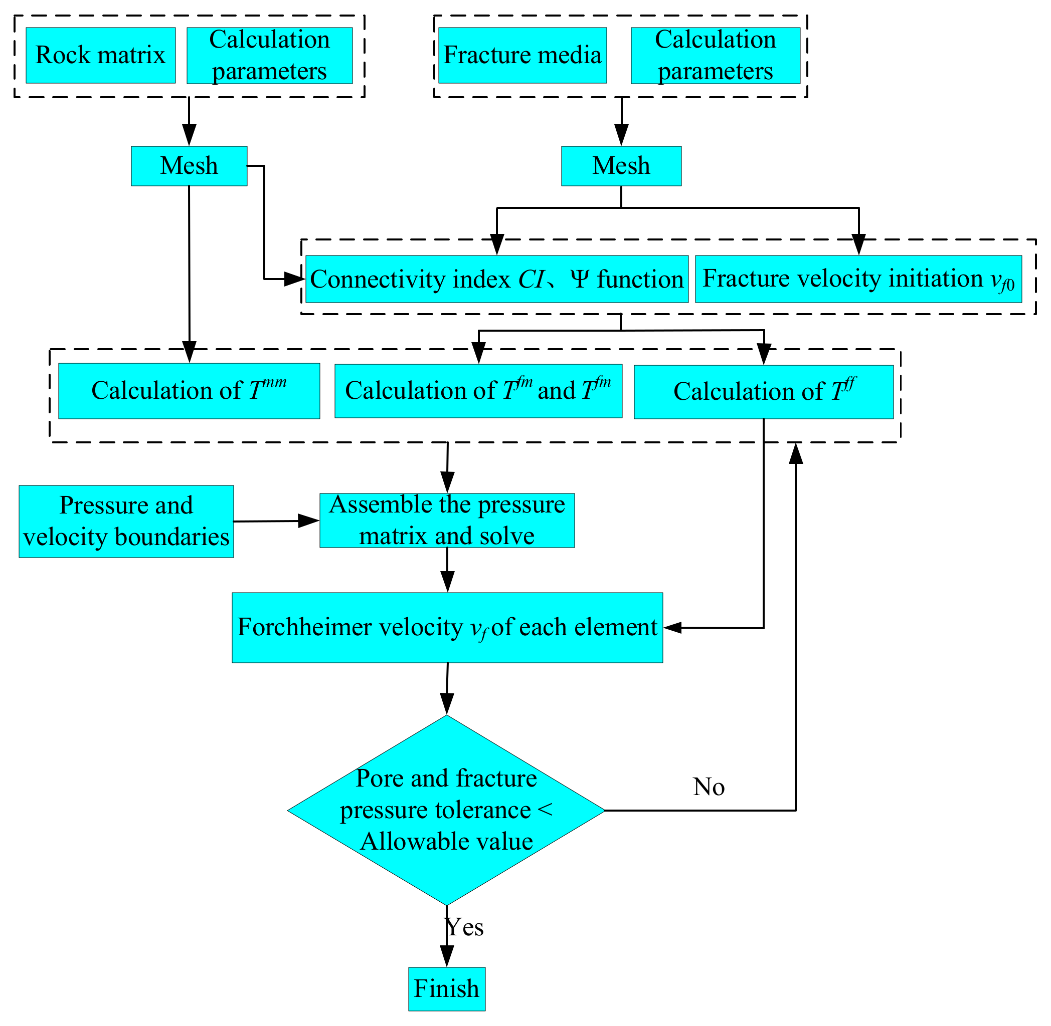
3.3. Solution Strategy

According to the solution steps of the finite volume method, a large sparse equation group T·x = A was obtained by assembling the pressure discrete equations of each element, including the seepage equations in porous media and fractured media. The coefficient matrix T is,
T = T m m T m f T f m T f f
where Tmm is the conduction matrix in porous media, Tff is the conduction matrix of fractures, including the conduction coefficient of fractures and their intersections. Tmf and Tfm comprise the pore–fracture exchange conduction matrix and the fracture–pore exchange conduction matrix. It is worth noting that the fracture conduction matrix Tff is a function of velocity, so the assembled equations are nonlinear. To solve the equations, a fixed-point iterative algorithm is used [26,27]. The method is described as follows: Based on the above calculation method, the MATLAB programming function is used to design the nonlinear seepage program in the dual media. The program flow chart is shown in Figure 2. As seen in Figure 2, the connectivity index CI and Ψ function are first calculated. At the same time, the fracture velocity is initiated. The conduction matrix of porous and fractured media is then determined. Considering pressure and velocity boundaries, the pressure matrix is assembled and solved. When pore and fracture pressure tolerance is smaller than the allowable value, the calculation finishes. If not, the calculation returns back to the conduction matrix calculation.

4. Validation

The two selected examples were reported by [24]. The two models were rectangular regions with a size of 2 × 1 m. Model 1 contained four fractures with an aperture of 0.01 m, which intersected at one point T1. Model 2 contains five fractures with an aperture of 0.01 m, which intersect at points T2 and T3. The permeability coefficient km of porous area is 10−9 m2, and the permeability coefficient of fracture is 10−7 m2. The boundary conditions are as follows: the water pressure is set as 106 and 0 Pa at the left and right boundaries of the porous region, 106 and 0 Pa at the upper and lower boundaries of the fracture, and the other boundaries are flow-free boundaries, as shown in Figure 3a,b. The fluid has a density of 1000 kg/m3 and a viscosity coefficient of 10 × 10−3 Pa·s. To illustrate the accuracy of the proposed method, error index e is used to represent the difference between the new method and the solutions of [24],
e = p New p F 2 p F 2 × 100 %
where p is the pressure distribution calculated by the new method, and pF is the pressure distribution calculated by [24]. Firstly, the pressure distribution of the case with a nonlinear parameter β = 10 and a mesh size of 0.02 m is simulated. Figure 4 shows the pressure distribution and fracture velocity distribution calculated by the new method. The calculated pressure distribution and fracture velocity distribution are consistent with the calculated results of [24].
In addition, the influence of different mesh sizes on the accuracy of the pressure solution was investigated. Figure 5 shows the relationship between mesh size h and the calculation error index e of the new method. It can be seen that for the mesh size range investigated, the calculation error index e decreases from 12% to 0.6% with decreasing mesh size. When the mesh size is less than 0.01 m, the error index is less than 1%, which indicates that the new method can describe the nonlinear seepage behavior in the dual media.

5. Nonlinear Seepage Analysis of Tunnel

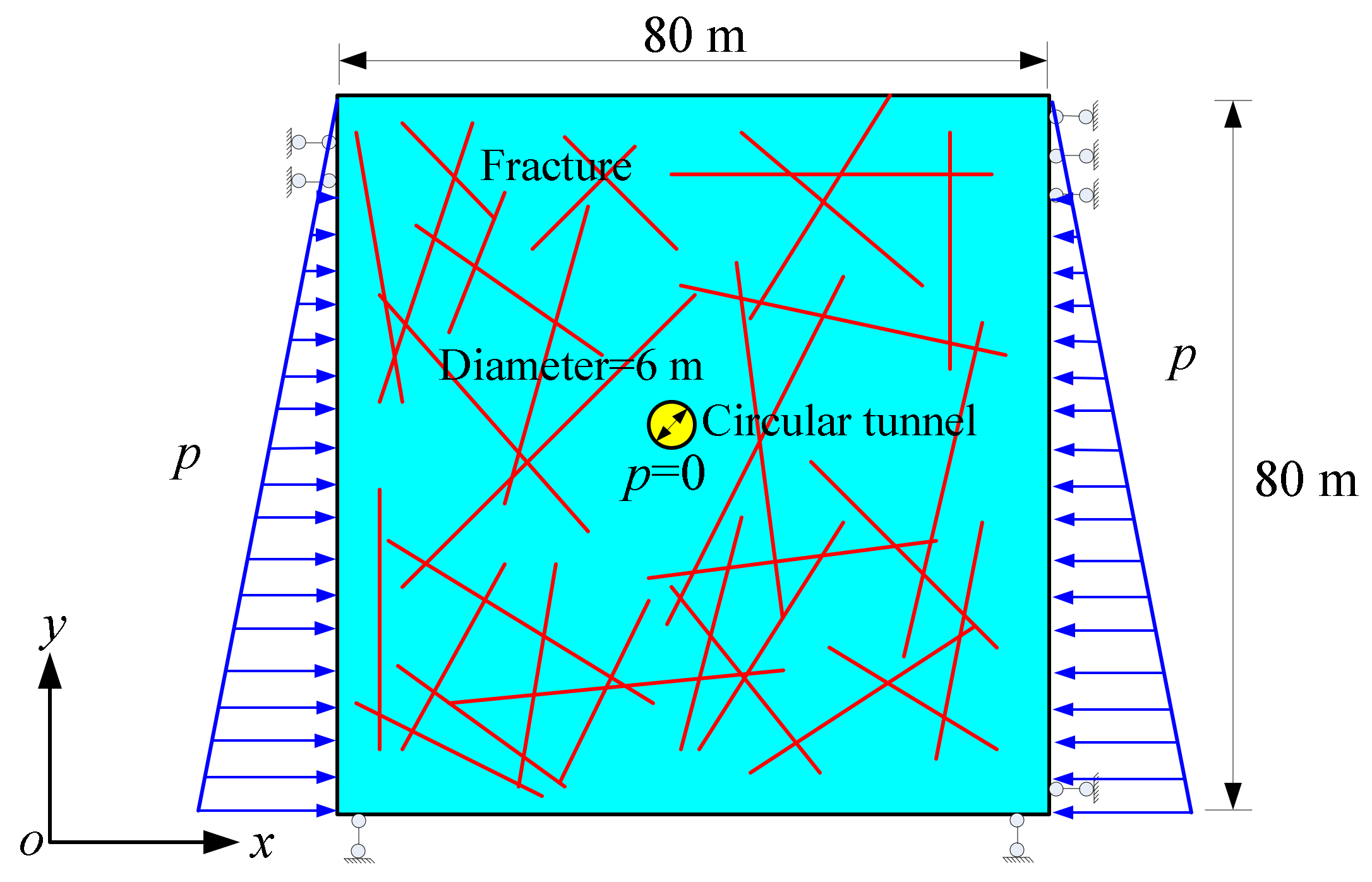
Model Setting and Calculating Parameters

Due to the complex geological conditions and large water pressure of buried fracture tunnels with rich water depth, the traditional calculation of cubic law would result in a large deviation from the field test. Therefore, it is necessary to analyze the seepage field of the tunnel surrounding the rock by using the Darcy–Forchheimer coupled flow method in the fractured rock mass.
As shown in Figure 6, a numerical model of the buried tunnel with rich water depth is divided into 10,000 quadrilateral elements, with a total number of 10,201 nodes and a size of 0.8 m. The length and height of the calculation model are 80 m and 80 m, respectively, according to the geological conditions of the site and the influence of the boundary. The tunnel is a circular tunnel with a radius of 3 m and the coordinates of the center of the circle are (40,40). The tunnel does not consider the support measures and implements internal drainage, so the tunnel water pressure p is 0 Pa. The calculation parameters were selected from the engineering geology report. The water density was set as 1000 kg/m3, the permeability coefficient of rock mass was 1 × 10⁻⁸ m2, the porosity was 0.3, and the fracture permeability coefficient was 1 × 10⁻⁵ m2. The viscosity of the fluid is 10 × 10−3 Pa × s.
In the simulation, it is assumed that the water supply of the surrounding rock far site is sufficient, and the underground water surface does not decrease with the tunnel drainage. Therefore, the groundwater level remains constant, and the water pressure is 0 Pa. The seepage field of the tunnel is linearly distributed along the numerical direction under the action of gravity and the gradient is fluid gravity. Therefore, the water pressure at the bottom is 8 × 10⁵ Pa (80 m head), and the water pressure on both sides is linear, as shown in Figure 6.
To simplify the calculation, the tunnel model does not consider the geological structure, such as strata and faults, and only simulates the influence of random fractures in surrounding rock. The fracture model was generated by the random Mento-Carlo method [33,34,35,36]. The position of the fracture obeys uniform distribution, and the length obeys exponential distribution,
f ( l ) = λ e λ l
where f(l) is the probability density function of fracture length, and λ is the exponential distribution parameter. The length of fracture is in the range of [lmin, lmax]. Another important parameter is the direction of the fracture. In the three-dimensional fracture, it refers to the inclination and dip angle of the fracture, while in the two-dimensional fracture system, it can be expressed by the angle of the fracture θ. The angle θ of fracture can be simulated by the von-Mises distribution,
f ( θ ) = e κ cos θ μ 2 π I 0 κ
I n ( κ ) = 1 π 0 π exp κ cos ( x ) cos n x d x
where μ is the mean value of fracture inclination and κ is the von-Mises distribution coefficient, which indicates the non-uniform distribution of fracture.

6. Result and Discussion

Based on the numerical method of nonlinear flow in dual media, the influences of fracture heterogeneity and density on the evolution of inrush flow in fractured surrounding rock tunnels are studied.
(1)
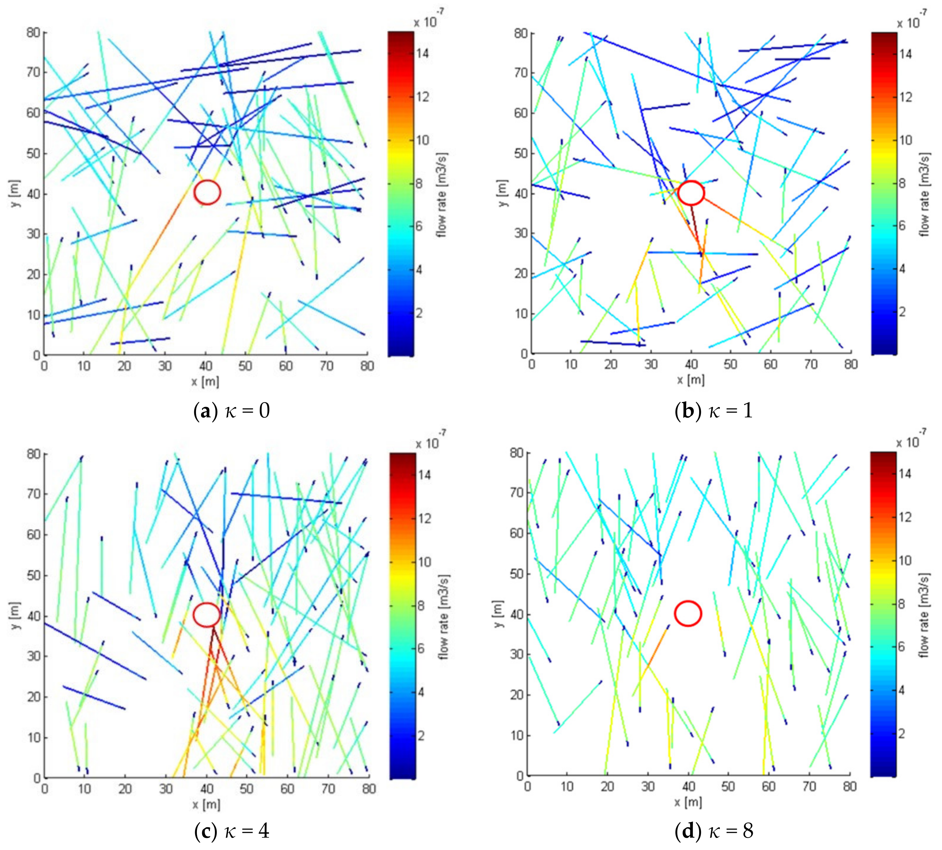
The effects of heterogeneity of fracture
To investigate the influence of fracture orientation inhomogeneity, the simulated fracture parameters κ are 0, 1, 2, 4, and 8. The larger κ is, the more non-homogenous the fracture distribution is. Other parameters are as follows: the aperture of all fractures is set at 0.1 mm, the length of fracture is between [10, 80] m, and the exponential distribution is λ = 1. The average fracture angle is 90°.
Figure 7 is the cloud map of water pressure distribution in a tunnel surrounding rock with different κ values. As can be seen, the water head of the whole flow field expands outward in concentric circles with the tunnel. The water pressure nephogram of surrounding rock with different κ values is slightly different, which indicates that the uniformity of fracture affects the water pressure distribution of surrounding rock in the tunnel. To better illustrate this difference, the water pressure in y = [30, 50] sections of the tunnel centerline at x = 40 was taken, and the water pressure distribution with different κ values was plotted as shown in Figure 8. The water pressure near the bottom of the tunnel changes greatly, with an average gradient of 8300 Pa/m, while the water pressure near the top of the tunnel changes less, with an average gradient of 3300 Pa/m. This suggests that the flow at the bottom of the tunnel is higher than at the top. In addition, the greater the κ value is, the greater the water pressure gradient around the tunnel is. But the influence on the surrounding rock at the bottom of the tunnel is less than that at the top of the tunnel. This indicates that the more the fracture direction is concentrated in the direction of the hydraulic gradient, the larger the tunnel flow will be.
Figure 9 shows the flow distribution of the fracture network with different κ values. As can be seen, the fracture flow distribution has obvious heterogeneity: the fracture flow along the flow direction (Y-axis) is large, the fracture flow along the vertical flow direction (X-axis) is small, and the maximum flow is about 60 times the minimum flow. The maximum fracture flow is distributed near the tunnel, ranging from 1 × 10⁻⁶ to 2 × 10⁻⁶ m3/s/m. The main reason is that there is a large hydraulic gradient at the tunnel exit, which is consistent with the analysis results of the above water pressure distribution.
(2)
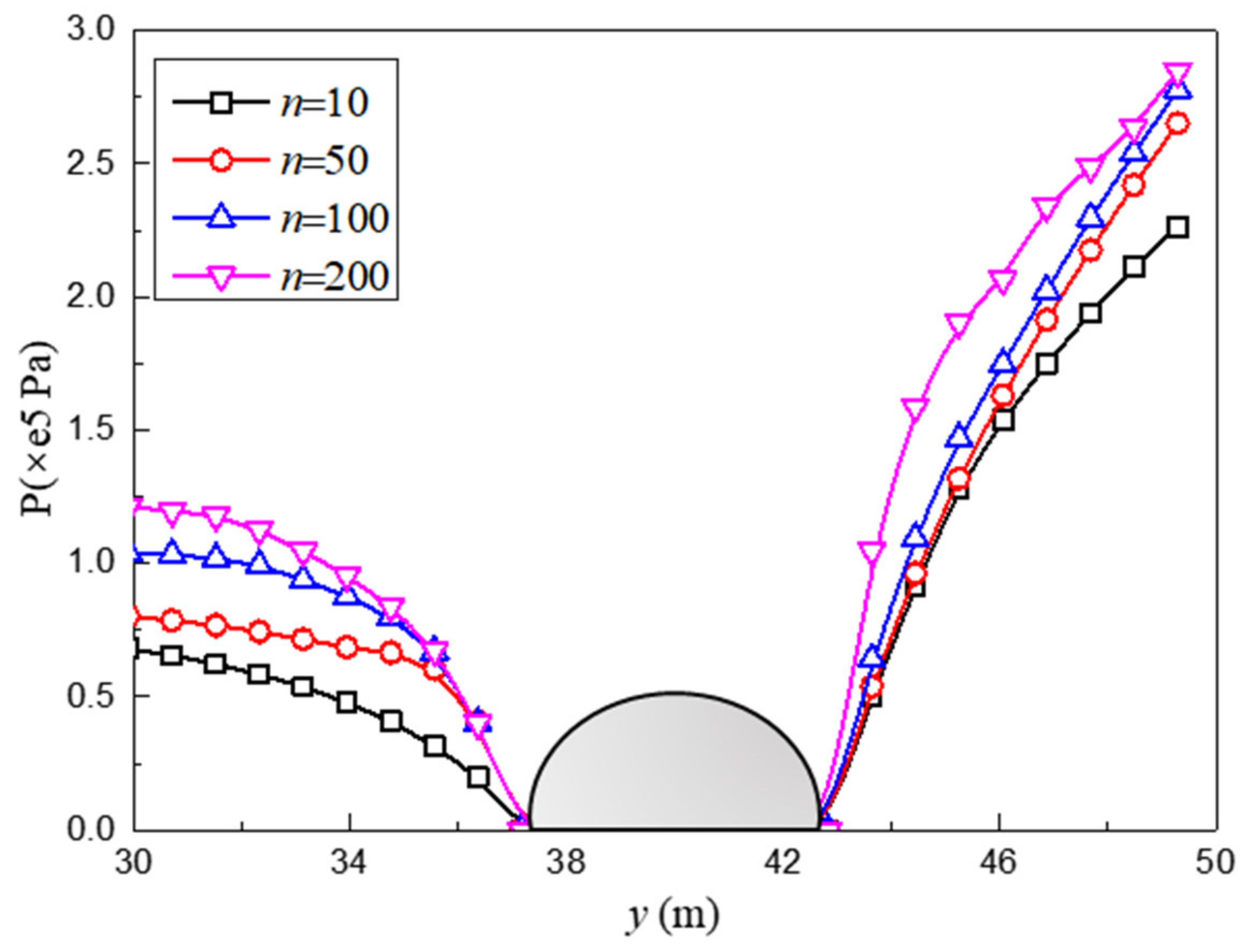
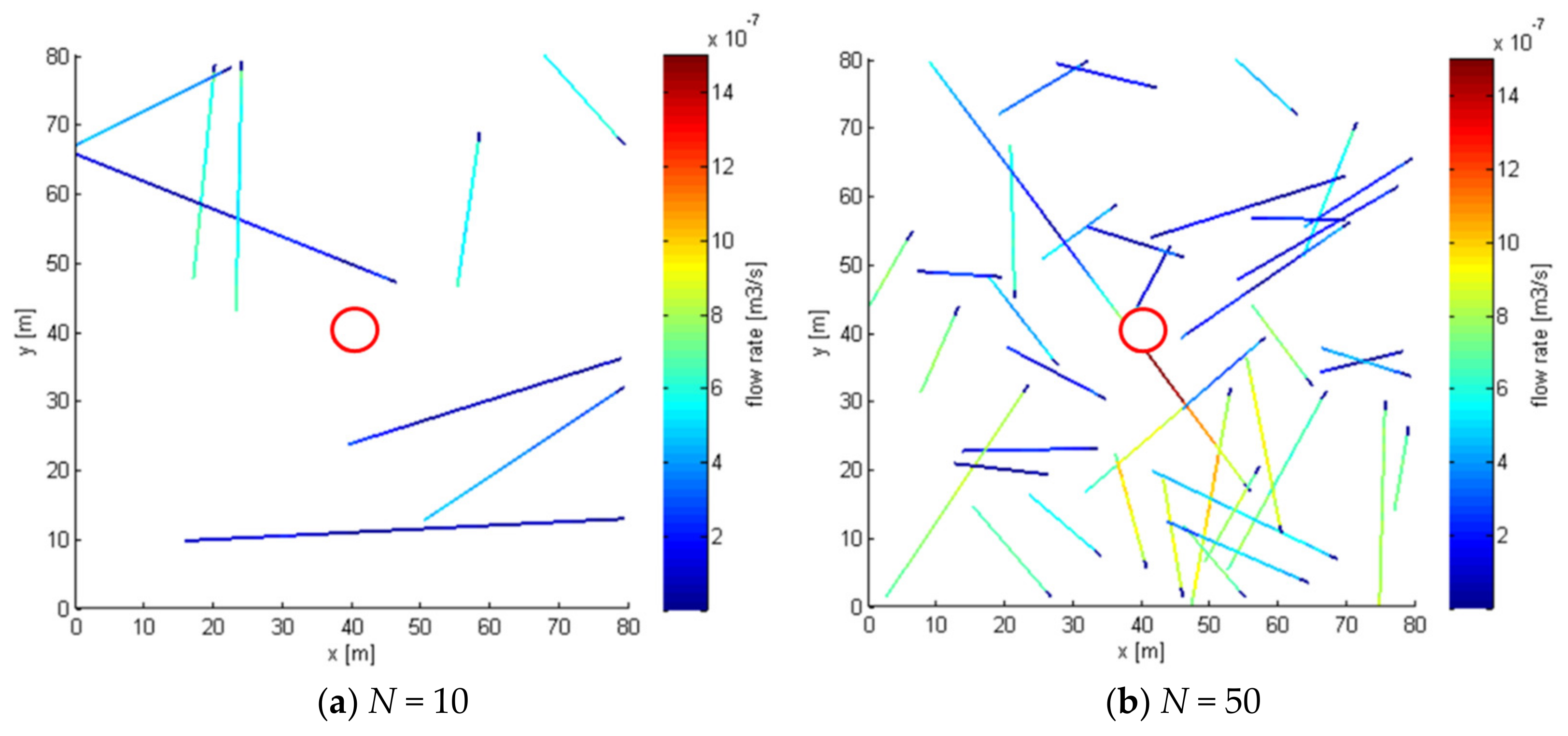
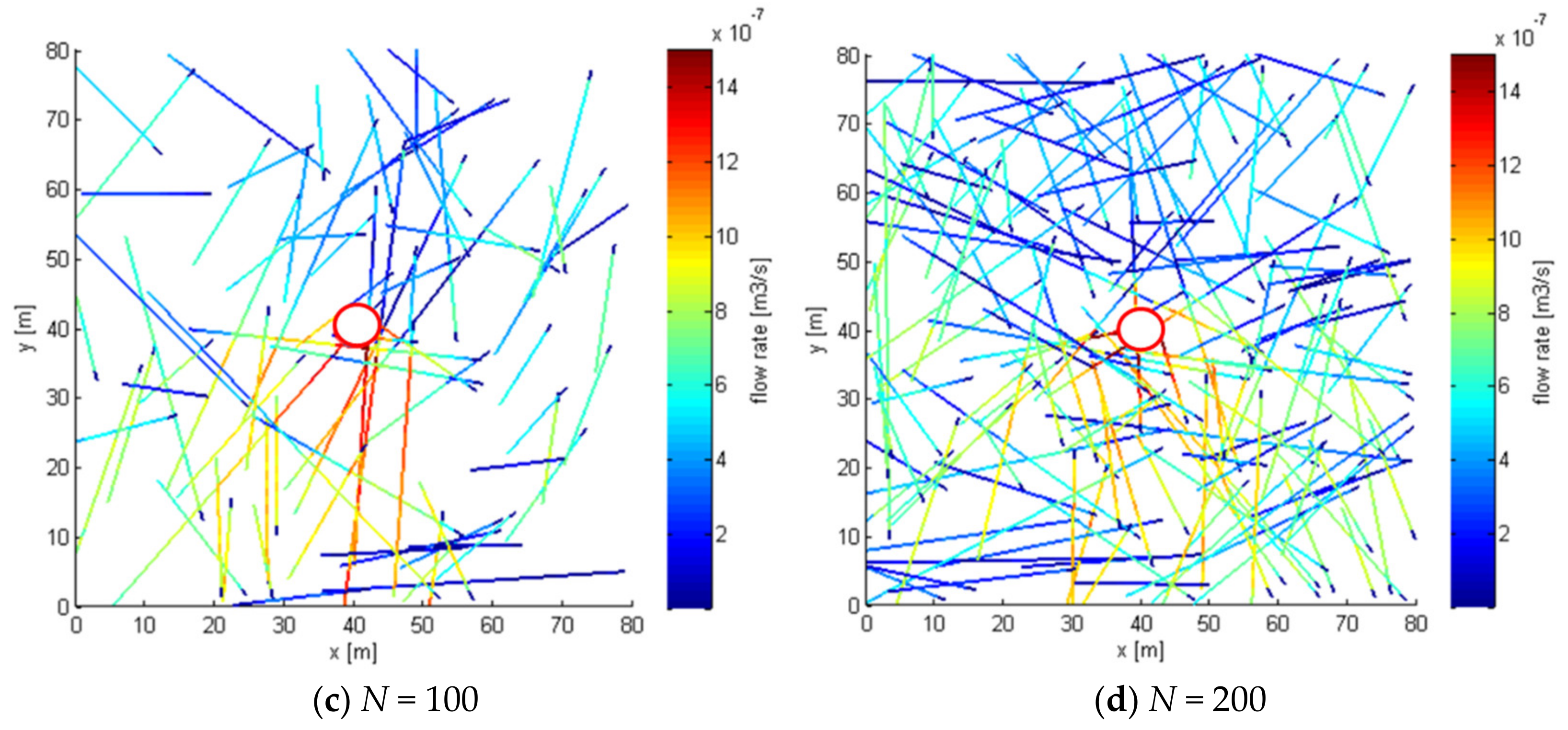
The effects of fracture density
The influence of the number of fractures on the seepage field of the tunnel surrounding rock is analyzed by changing the number of fractures. The number of fractures is 10, 50, 100, 150, 200, and 300. The other parameters are the same as in section (1). Figure 10 shows the distribution of water pressure and velocity of surrounding rock under different N values. The water pressure distribution around the tunnel is less affected by the number of fractures. Similarly, the water pressure at y = [30, 50] of the tunnel centerline with x = 40 was taken, and the water pressure distribution with different N values were drawn, as shown in Figure 11. The greater the value of N, the greater the water pressure gradient around the tunnel. However, the influence of N value change on the surrounding rock at the tunnel bottom is less than that at the tunnel top. This indicates that the greater the number of fractures, the greater the water pressure gradient of the tunnel surrounding rock is, and the greater the tunnel flow is.
In addition, the flow distribution of the fracture network under different N values was calculated, as shown in Figure 12. It can be seen that the N value will affect the flow distribution of the fracture. The larger the value of N, the more fractures with high flow there are, although mainly distributed near the tunnel. The main reason for this is that the N value affects the number of fractures. The larger the N value, the more fractures there are, and the more likely they are to intersect with the tunnel, resulting in more fractures with high flow.
In conclusion, the distribution heterogeneity and density of fracture are the key factors affecting the pressure field and water inflow of fractured surrounding rock tunnels. For deep-buried water-rich fractured tunnels, the more the fracture direction is concentrated in the direction of water pressure and the higher the density is, the more water-gushing accidents will occur in the tunnels. Therefore, it is necessary to find out the relevant geological body information, such as fractures and faults, in time and take all-inclusive waterproofing measures when necessary.
It is also noted that the representativeness of fracture distribution uses two parameters, namely fracture heterogeneity and density. This work focus on the effects of fracture heterogeneity and density on flow behavior in the tunnel. Although the generation of fractures is based on the Monte Carlo method, the influences originate from several fracture network models. Hence, the results are applicable to flow in fractured rock tunnels.

7. Conclusions

Based on the finite volume method, the discrete scheme of the Darcy flow equation in porous media and the Forchheimer flow equation in the fracture is derived, and the solution method of the coupled flows is proposed. Based on this method, the nonlinear seepage law of buried fractured surrounding rock tunnel with rich water depth is studied, and the main conclusions are as follows:
(1)
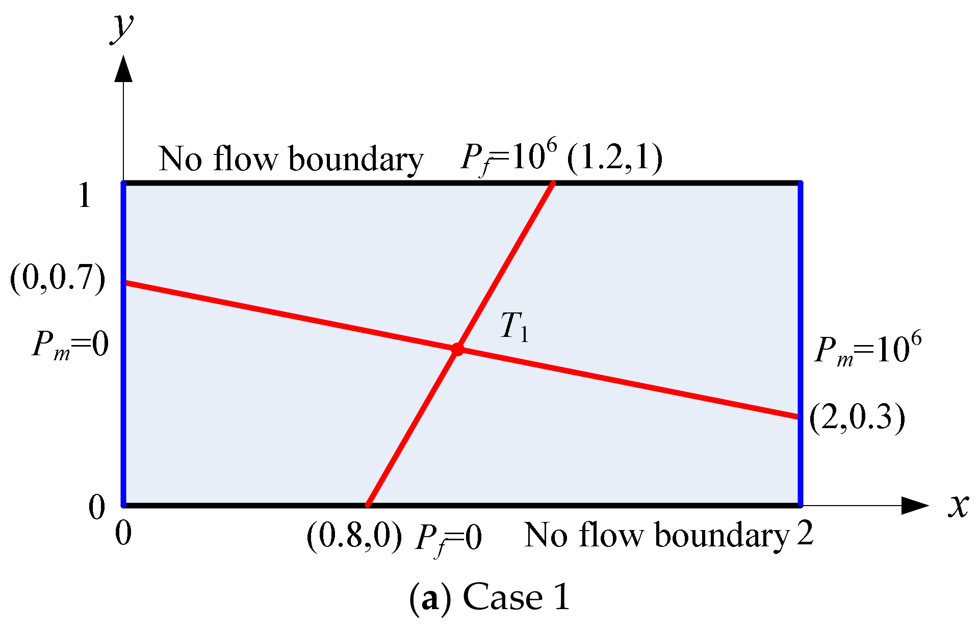
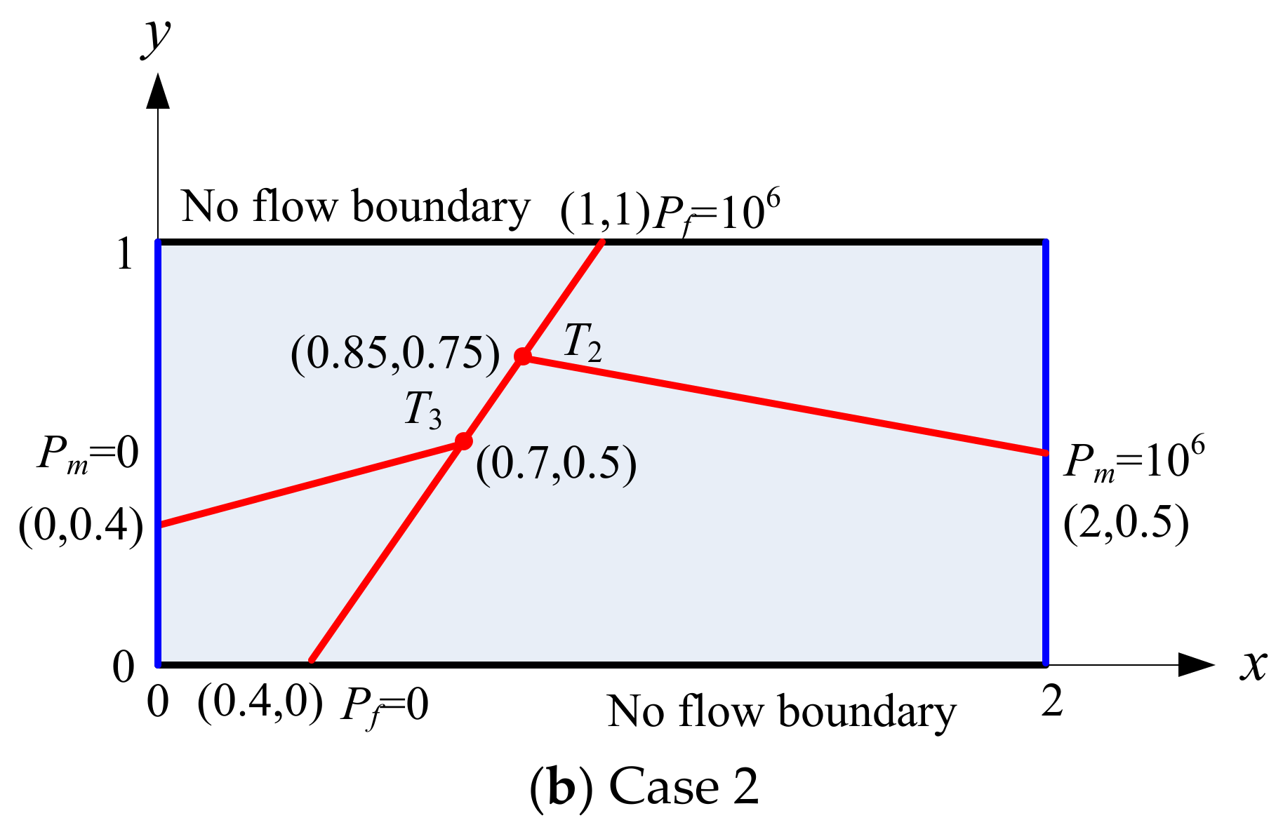
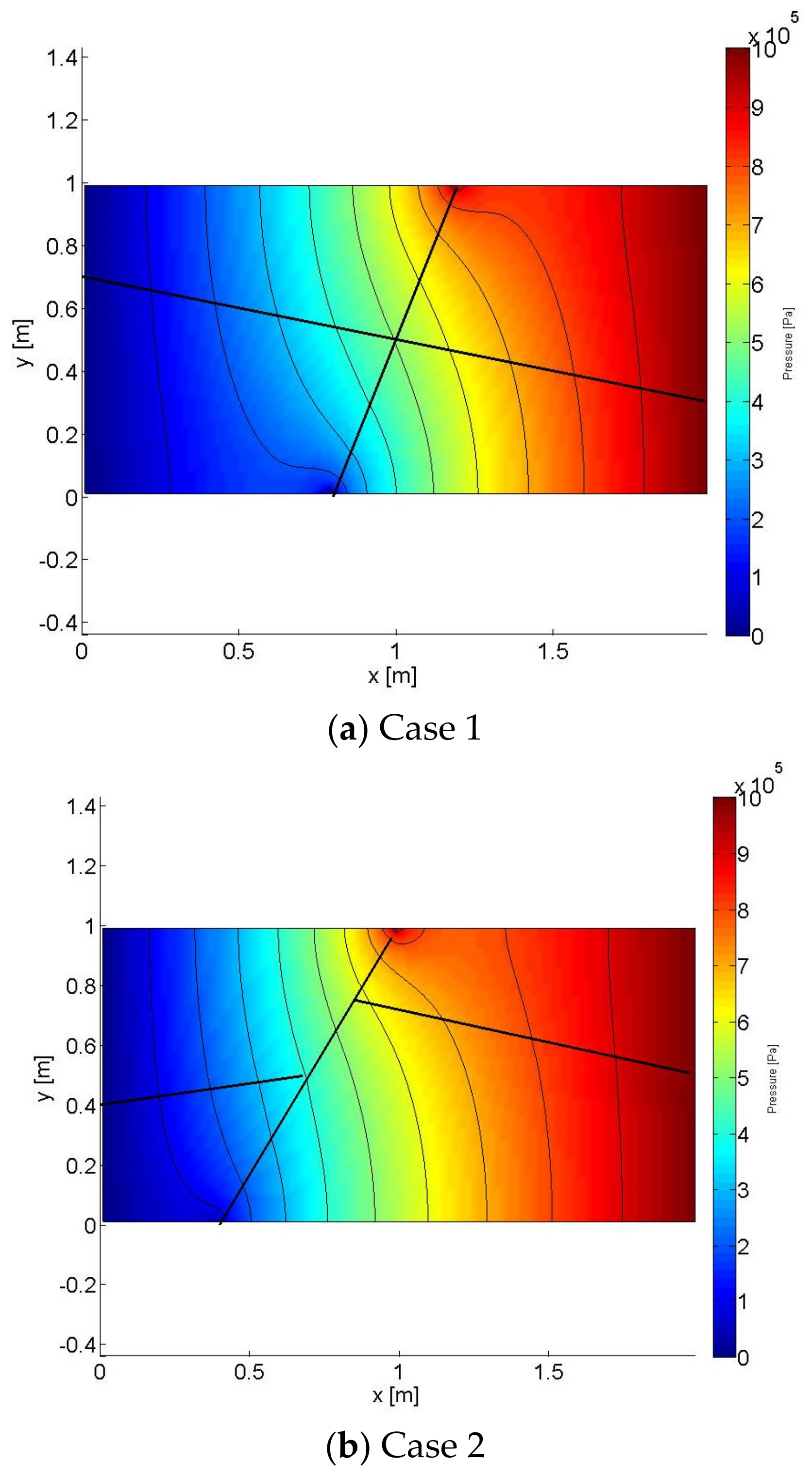
The results of the new method are compared with those of Frih et al. (2008) for intersecting fracture cases. The pressure and fracture velocity distributions calculated by the new method are consistent with those calculated by Frih et al. (2008). When the mesh size is less than 0.02 m, the calculation error is less than 1%. Therefore, the new method can accurately describe the nonlinear seepage behavior in fractured and porous media.
(2)
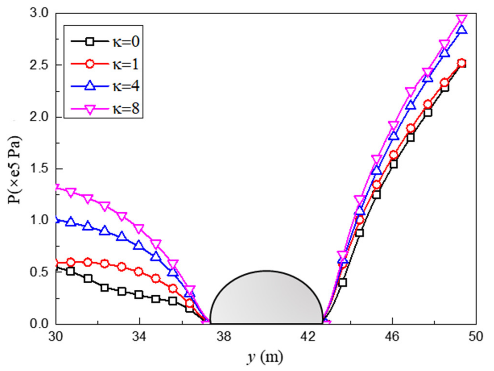
The water pressure gradient of the surrounding rock in the fractured tunnel presents the characteristics of “large at the bottom and small at the top”, which indicates that the flow at the bottom of the tunnel is higher than that at the top. In addition, the fracture flow along the flow direction is large, the vertical flow direction is small, and the maximum flow is 60 times the minimum flow.
(3)
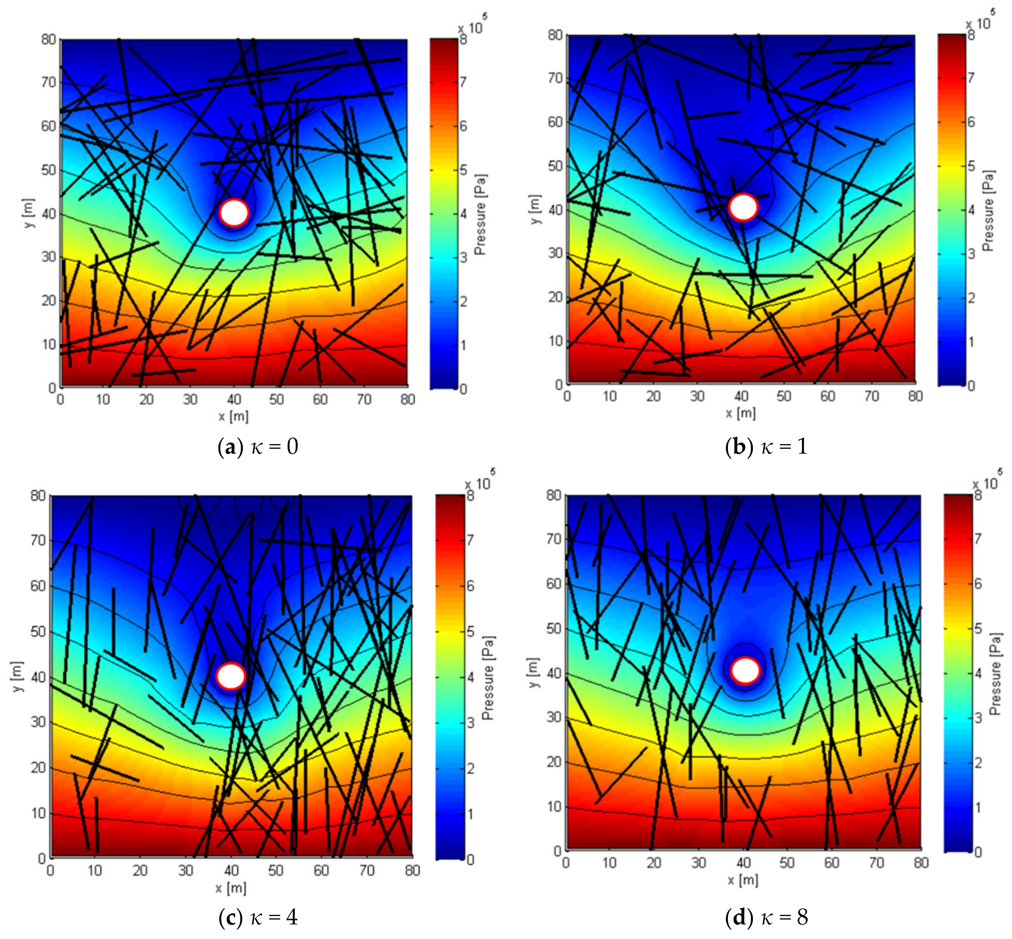
The random fracture uniformity affects the hydraulic characteristics of the tunnel surrounding the rock. The more the fracture direction is concentrated in the direction of the hydraulic gradient, the stronger the conductivity of the surrounding rock is and the greater the water inflow is.
(4)
Fracture density is another important factor affecting the conductivity of the tunnel surrounding the rock. The greater the fracture density, the greater the water pressure gradient and the greater the tunnel flow. The main reason is that the larger the fracture density is, the more fractures there are, and the more likely it is to intersect with the tunnel, resulting in more fractures with high flow. It is also noted that although the generation of fractures is based on the Monte Carlo method, the influences originate from several fracture network models. Hence, the new insights are applicable to flow in fractured rock tunnels.

Author Contributions

Conceptualization, F.X. and Y.J.; methodology, L.T.; software, Y.W.; validation, F.X., H.C. and C.Z.; formal analysis, C.Z.; investigation, F.X.; resources, C.Z.; data curation, H.C.; writing—original draft preparation, F.X.; writing—review and editing, Y.J.; visualization, L.T.; supervision, L.T.; project administration, L.T.; funding acquisition, Y.J. All authors have read and agreed to the published version of the manuscript.

Funding

This research was funded by the Supported by Open Research Fund of State Key Laboratory of Geomechanics and Geotechnical Engineering, Institute of Rock and Soil Mechanics, Chinese Academy of Sciences (Grant No. SKLGME021009), the Fundamental Research Funds for the central Universities, CHD (Grant No. 300102212523), the National Natural Science Foundation of China (Grant No. 52209148), the National Natural Science Foundation of Shandong Province, China (Grant No. ZR2022ME188) and National Key Research and Development projects of China (Grant No. 2021YFB2600402).

Institutional Review Board Statement

Not applicable.

Informed Consent Statement

Not applicable.

Data Availability Statement

The data presented in this study are available on request from the corresponding author.

Acknowledgments

This work was supported by the Supported by Open Research Fund of State Key Laboratory of Geomechanics and Geotechnical Engineering, Institute of Rock and Soil Mechanics, Chinese Academy of Sciences (Grant No. SKLGME021009), the Fundamental Research Funds for the central Universities, CHD (Grant No. 300102212523), the National Natural Science Foundation of China (Grant No. 52209148), the National Natural Science Foundation of Shandong Province, China (Grant No. ZR2022ME188) and National Key Research and Development projects of China (Grant No. 2021YFB2600402). This support is gratefully acknowledged.

Conflicts of Interest

The authors declare no conflict of interest.

References

  1. He, M.; Sui, Q.; Li, M.; Wang, Z.; Tao, Z. Compensation excavation method control for large deformation disaster of mountain soft rock tunnel. Int. J. Min. Sci. Technol. 2022, 32, 951–963. [Google Scholar] [CrossRef]
  2. Zhu, C.; Xu, X.; Wang, X.; Xiong, F.; Tao, Z.; Lin, Y.; Chen, J. Experimental Investigation on Nonlinear Flow Anisotropy Behavior in Fracture Media. Geofluids 2019, 2019, 5874849. [Google Scholar] [CrossRef]
  3. Yin, Q.; Wu, J.; Jiang, Z.; Zhu, C.; Su, H.; Jing, H.; Gu, X. Investigating the effect of water quenching cycles on mechanical behaviors for granites after conventional triaxial compression. Geomech. Geophys. Geo Energy Geo Resour. 2022, 8, 77. [Google Scholar] [CrossRef]
  4. Wang, Y.; Zhu, C.; He, M.; Wang, X.; Le, H. Macro-meso dynamic fracture behaviors of Xinjiang marble exposed to freeze thaw and frequent impact disturbance loads: A lab-scale testing. Geomech. Geophys. Geo Energy Geo Resour. 2022, 8, 154. [Google Scholar] [CrossRef]
  5. Zhu, C.; Xu, Y.; Wu, Y.; He, M.; Zhu, C.; Meng, Q.; Lin, Y. A hybrid artifi cial bee colony algorithm and support vector machine for predicting blast-induced ground vibration. Earthq. Eng. Eng. Vib. 2022, 21, 861–876. [Google Scholar] [CrossRef]
  6. Tang, S.; Li, J.; Ding, S.; Zhang, L. The influence of water-stress loading sequences on the creep behavior of granite. Bull. Eng. Geol. Environ. 2022, 81, 482. [Google Scholar] [CrossRef]
  7. Liang, X.; Tang, S.; Tang, C.; Hu, L.; Chen, F. Influence of Water on the Mechanical Properties and Failure Behaviors of Sandstone Under Triaxial Compression. Rock Mech. Rock Eng. 2022, 1–32. [Google Scholar] [CrossRef]
  8. Lei, Q.; Latham, J.-P.; Tsang, C.-F. The use of discrete fracture networks for modelling coupled geomechanical and hydrological behaviour of fractured rocks. Comput. Geotech. 2017, 85, 151–176. [Google Scholar] [CrossRef]
  9. Huyakorn, P.; Lester, B.; Faust, C. Finite element techniques for modeling groundwater flow in fractured aquifers. Water Resour. Res. 1983, 19, 1019–1035. [Google Scholar] [CrossRef]
  10. Athani, S.S.; Shivamanth; Solanki, C.; Dodagoudar, G. Seepage and Stability Analyses of Earth Dam Using Finite Element Method. Aquat. Procedia 2015, 4, 876–883. [Google Scholar] [CrossRef]
  11. Maryška, J.; Severýn, O.; Vohralik, M. Numerical simulation of fracture flow with a mixed-hybrid FEM stochastic discrete fracture network model. Comput. Geosci. 2005, 8, 217–234. [Google Scholar] [CrossRef]
  12. Zimmerman, R.W.; Hadgu, T.; Bodvarsson, G.S. A new lumped-parameter model for flow in unsaturated dual-porosity media. Adv. Water Resour. 1996, 19, 317–327. [Google Scholar] [CrossRef]
  13. Peratta, A.; Popov, V. A new scheme for numerical modelling of flow and transport processes in 3D fractured porous media. Adv. Water Resour. 2006, 29, 42–61. [Google Scholar] [CrossRef]
  14. Huang, H.; Ayoub, J. Applicability of the Forchheimer equation for non-Darcy flow in porous media. In Proceedings of the SPE Annual Technical Conference and Exhibition, San Antonio, TX, USA, 24–27 September 2006. [Google Scholar]
  15. Barree, R.; Conway, M.W. Beyond beta factors: A complete model for Darcy, Forchheimer, and Trans-Forchheimer flow in porous media. In Proceedings of the SPE Annual Technical Conference and Exhibition, Houston, TX, USA, 26–29 September 2004. [Google Scholar]
  16. Chen, Z.; Lyons, S.; Qin, G. Derivation of the Forchheimer law via homogenization. Transp. Porous Media 2001, 44, 325–335. [Google Scholar] [CrossRef]
  17. Giorgi, T. Derivation of the Forchheimer law via matched asymptotic expansions. Transp. Porous Media 1997, 29, 191–206. [Google Scholar] [CrossRef]
  18. Douglas, J.; Paes-Leme, P.J.; Giorgi, T. Generalized Forchheimer flow in porous media. In Boundary Value Problems for Partial Differential Equations and Applications; Lions, J.-L., Baiocchi, C., Eds.; Masson: Paris, France, 1993; Volume 29, pp. 99–111. [Google Scholar]
  19. Xu, W.; Liang, D.; Rui, H. A multipoint flux mixed finite element method for the compressible Darcy–Forchheimer models. Appl. Math. Comput. 2017, 315, 259–277. [Google Scholar] [CrossRef]
  20. Tang, Z.C.; Jiao, Y.Y.; Wong, L.N.Y. Theoretical model with multi-asperity interaction for the closure behavior of rock joint. Int. J. Rock Mech. Min. Sci. 2017, 97, 15–23. [Google Scholar] [CrossRef]
  21. Tang, Z.C.; Xia, C.C.; Jiao, Y.Y.; Wong, L.N.Y. Closure model with asperity interaction in normal contact for rock joint. Int. J. Rock Mech. Min. Sci. 2016, 83, 170–173. [Google Scholar] [CrossRef]
  22. Xiong, F.; Wei, W.; Xu, C.; Jiang, Q. Experimental and numerical investigation on nonlinear flow behaviour through three dimensional fracture intersections and fracture networks. Comput. Geotech. 2020, 121, 103446. [Google Scholar] [CrossRef]
  23. Lang, P.S.; Paluszny, A.; Zimmerman, R.W. Permeability tensor of three-dimensional fractured porous rock and a comparison to trace map predictions. J. Geophys. Res. Solid Earth. 2014, 119, 6288–6307. [Google Scholar] [CrossRef]
  24. Frih, N.; Roberts, J.E.; Saada, A. Modeling fractures as interfaces: A model for Forchheimer fractures. Comput. Geosci. 2008, 12, 91–104. [Google Scholar] [CrossRef] [Green Version]
  25. Arrars, A.; Gaspar, F.J.; Portero, L.; Rodrigo, C. Geometric multigrid methods for Darcy-Forchheimer flow in fractured porous media. Comput. Math. Appl. 2019, 78, 3139–3151. [Google Scholar] [CrossRef] [Green Version]
  26. Xiong, F.; Sun, H.; Ye, Z.; Zhang, Q. Heat extraction analysis for nonlinear heat flow in fractured geothermal reservoirs. Comput. Geotech. 2022, 144, 104641. [Google Scholar] [CrossRef]
  27. Xiong, F.; Sun, H.; Zhang, Q.; Wang, Y.; Jiang, Q. Preferential flow in three-dimensional stochastic fracture networks: The effect of topological structure. Eng. Geol. 2022, 309, 106856. [Google Scholar] [CrossRef]
  28. Farhadian, H.; Katibeh, H.; Huggenberger, P.; Butscher, C. Optimum model extent for numerical simulation of tunnel inflow in fractured rock. Tunn. Undergr. Sp. Technol. 2016, 60, 21–29. [Google Scholar] [CrossRef]
  29. Moeini, H.; Farhadian, H.; Nikvar-Hassani, A. Determination of theoptimum sealing method for Azad pumped storage dam considering seepage analysis. Arab. J. Geosci. 2018, 11, 389. [Google Scholar] [CrossRef]
  30. Chorin, A.J.; Marsden, J.E. A Mathematical Introduction to Fluid Mechanics; Springer: New York, NY, USA, 1979; Volume 3. [Google Scholar]
  31. Hajibeygi, H.; Karvounis, D.; Jenny, P. A hierarchical fracture model for the iterative multiscale finite volume method. J. Comput. Phys. 2011, 230, 8729–8743. [Google Scholar] [CrossRef]
  32. Karimi-Fard, M.; Durlofsky, L.J.; Aziz, K. An efficient discrete-fracture model applicable for general-purpose reservoir simulators. SPE J. 2004, 9, 227–236. [Google Scholar] [CrossRef]
  33. Xu, C.; Dowd, P. A new computer code for discrete fracture network modelling. Comput. Geosci. 2013, 36, 292–301. [Google Scholar] [CrossRef]
  34. Dou, Z.; Zhou, Z.; Sleep, B.E. Influence of wettability on interfacial area during immiscible liquid invasion into a 3D self-affine rough fracture: Lattice Boltzmann simulations. Adv. Water Resour. 2013, 61, 1–11. [Google Scholar] [CrossRef]
  35. Dou, Z.; Zhou, Z.; Wang, J.; Huang, Y. Roughness scale dependence of the relationship between tracer longitudinal dispersion and Peclet number in variable-aperture fractures. Hydrol. Process. 2018, 32, 1461–1475. [Google Scholar] [CrossRef]
  36. Wang, H.; Li, H.; Tang, L.; Ren, X.; Meng, Q.; Zhu, C. Fracture of two three-dimensional parallel internal cracks in brittle solid under ultrasonic fracturing. J. Rock Mech. Geotech. Eng. 2022, 14, 757–769. [Google Scholar] [CrossRef]
Figure 1. Schematic diagram of fractured porous media.
Applsci 13 00344 g001
Figure 2. Flowchart of coupling Darcy–Forchheimer flow in fractured porous media.
Applsci 13 00344 g002
Figure 3. Geometry model of intersecting fracture cases.
Applsci 13 00344 g003aApplsci 13 00344 g003b
Figure 4. Pressure distribution of two cases.
Applsci 13 00344 g004
Figure 5. Relationship of error and mesh size for intersecting fracture case.
Applsci 13 00344 g005
Figure 6. Geometry model of tunnel.
Applsci 13 00344 g006
Figure 7. Water pressure distribution of fractured rock tunnel under different κ values.
Applsci 13 00344 g007
Figure 8. Water pressure distribution of tunnel rock at [30, 50] range under different κ values.
Applsci 13 00344 g008
Figure 9. Fracture flow rate distribution under different κ values.
Applsci 13 00344 g009
Figure 10. Water pressure distribution of fractured rock tunnel under different fracture numbers.
Applsci 13 00344 g010
Figure 11. Water pressure distribution of tunnel rock at [30, 50] range under different fracture numbers.
Applsci 13 00344 g011
Figure 12. Fracture flow rate distribution under different fracture numbers.
Applsci 13 00344 g012aApplsci 13 00344 g012b
Disclaimer/Publisher’s Note: The statements, opinions and data contained in all publications are solely those of the individual author(s) and contributor(s) and not of MDPI and/or the editor(s). MDPI and/or the editor(s) disclaim responsibility for any injury to people or property resulting from any ideas, methods, instructions or products referred to in the content.

