
Silica Microsphere WGMR-Based Kerr-OFC Light Source and Its Application for High-Speed IM/DD Short-Reach Optical Interconnects

 ,
,  , , , ,
  ,
,  ,
,  and
and
Abstract
:1. Introduction
2. Characteristics of Designed Silica Microsphere WGMR for Kerr-OFC
3. Experimental Setup of Designed Silica Microsphere WGMR-Based Kerr-OFC as A Light Source for Application in Optical Communications
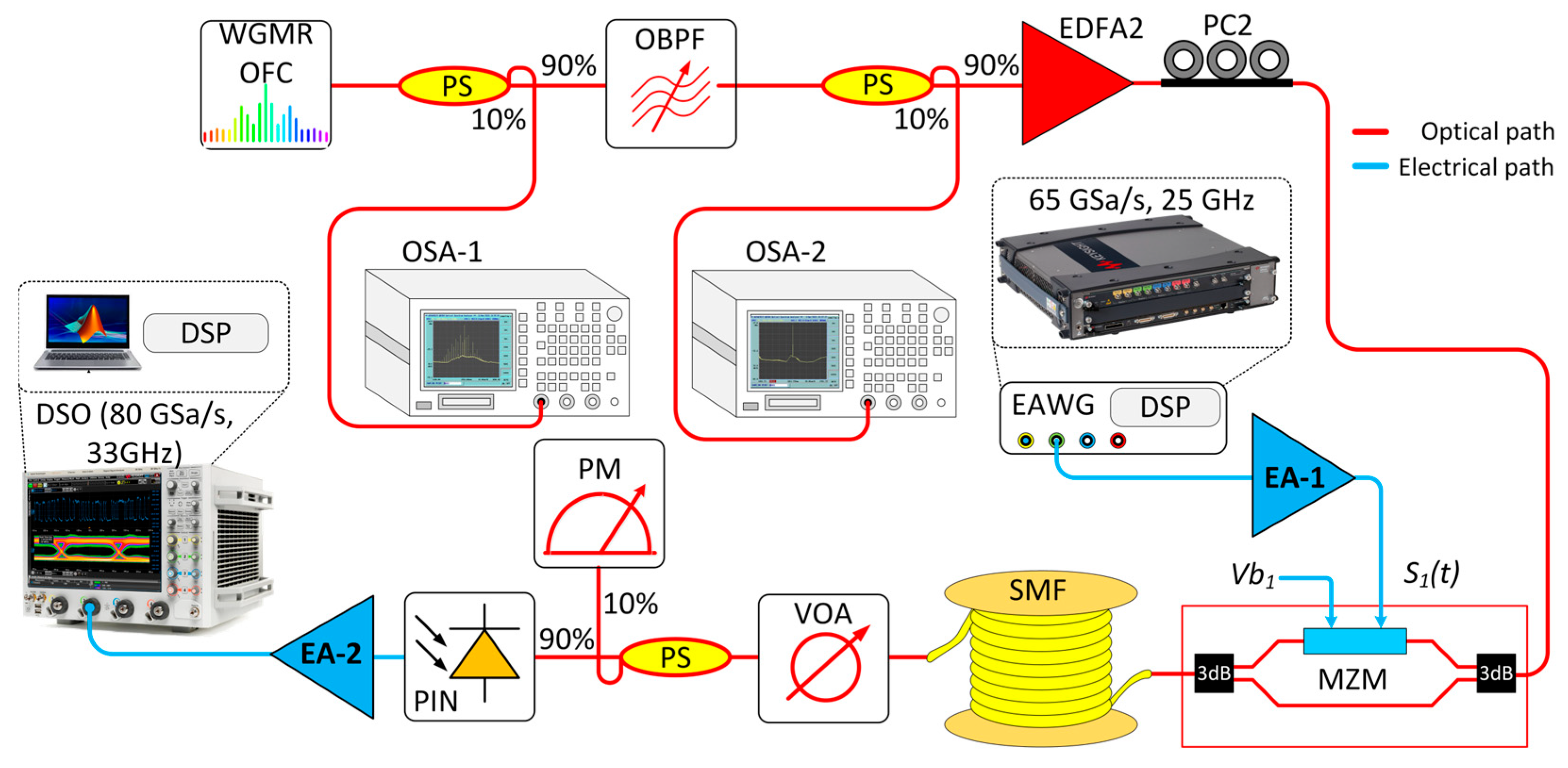
4. Experimental Setup of the Silica Microsphere WGMR-Based Kerr-OFC Light Source for Its Use in High-Speed IM/DD Short-Reach Optical Interconnects
5. Experimental Results
6. Conclusions
Author Contributions
Funding
Institutional Review Board Statement
Informed Consent Statement
Data Availability Statement
Acknowledgments
Conflicts of Interest
References
- Torres-Company, V.; Weiner, A.M. Optical frequency comb technology for ultra-broadband radio-frequency photonics. Laser Photonics Rev. 2014, 8, 368–393. [Google Scholar] [CrossRef] [Green Version]
- Ludlow, A.D.; Boyd, M.M.; Ye, J.; Peik, E.; Schmidt, P.O. Optical atomic clocks. Rev. Mod. Phys. 2015, 87, 637–701. [Google Scholar] [CrossRef]
- Kwon, D.; Jeon, I.; Lee, W.K.; Heo, M.S.; Kim, J. Generation of multiple ultrastable optical frequency combs from an all-fiber photonic platform. Sci. Adv. 2020, 6, eaax4457. [Google Scholar] [CrossRef] [PubMed] [Green Version]
- Predehl, K.; Grosche, G.; Raupach, S.M.F.; Droste, S.; Terra, O.; Alnis, J.; Legero, T.; Hänsch, T.W.; Udem, T.; Holzwarth, R.; et al. A 920-km optical fiber link for frequency metrology at the 19th decimal place. Science 2012, 336, 441–444. [Google Scholar] [CrossRef] [PubMed]
- Adler, F.; Thorpe, M.J.; Cossel, K.C.; Ye, J. Cavity-enhanced direct frequency comb spectroscopy: Technology and applications. Annu. Rev. Anal. Chem. 2010, 3, 175–205. [Google Scholar] [CrossRef] [Green Version]
- Guay, P.; Hébert, N.B.; Michaud-Belleau, V.; Lancaster, D.G.; Genest, J. Free-running optical frequency combs for remote sensing. In Optical Sensors and Sensing Congress (ES, FTS, HISE, Sensors), OSA Technical Digest; Optica Publishing Group: Washington, DC, USA, 2019. [Google Scholar] [CrossRef]
- Lu, H.H.; Weiner, A.M.; Lougovski, P.; Lukens, J.M. Quantum Information Processing with Frequency-Comb Qudits. IEEE Photon. Technol. Lett. 2019, 31, 1858–1861. [Google Scholar] [CrossRef]
- Pfeifle, J.; Brasch, V.; Lauermann, M.; Yimin, Y.; Wegner, D.; Herr, T.; Hartinger, K.; Schindler, P.; Li, J.; Hillerkuss, D.; et al. Coherent terabit communications with microresonator Kerr frequency combs. Nat. Photon 2014, 8, 375–380. [Google Scholar] [CrossRef] [Green Version]
- Salgals, T.; Alnis, J.; Murnieks, R.; Brice, I.; Porins, J.; Andrianov, A.V.; Anashkina, E.A.; Spolitis, S.; Bobrovs, V. Demonstration of a fiber optical communication system employing a silica microsphere-based OFC source. Opt. Express 2021, 29, 10903. [Google Scholar] [CrossRef]
- Kong, D.; Xin, H.; Kim, K.; Liu, Y.; Oxenløwe, L.K.; Dong, P.; Hu, H. Intra-Datacenter Interconnects With a Serialized Silicon Optical Frequency Comb Modulator. J. Lightwave Technol. 2020, 38, 4677–4682. [Google Scholar] [CrossRef]
- Pang, X.; Udalcovs, A.; Schatz, R.; Bobrovs, V.; Jacobsen, G.; Popov, S.; Ozolins, O. Short Reach Communication Technologies for Client-Side Optics Beyond 400 Gbps. IEEE Photon. Technol. Lett. 2021, 33, 1046–1049. [Google Scholar] [CrossRef]
- Spolitis, S.; Murnieks, R.; Skladova, L.; Salgals, T.; Andrianov, A.V.; Marisova, M.P.; Leuchs, G.; Anashkina, E.A.; Bobrovs, V. IM/DD WDM-PON Communication System Based on Optical Frequency Comb Generated in Silica Whispering Gallery Mode Resonator. IEEE Access 2021, 9, 66335–66345. [Google Scholar] [CrossRef]
- Hu, H.; Oxenløwe, L.K. Chip-based optical frequency combs for high-capacity optical communications. Nanophotonics 2021, 10, 1367–1385. [Google Scholar] [CrossRef]
- Wu, R.; Supradeepa, V.R.; Long, C.M.; Leaird, D.E.; Weiner, A.M. Generation of very flat optical frequency combs from continuous-wave lasers using cascaded intensity and phase modulators driven by tailored radio frequency waveforms. Opt. Lett. 2010, 35, 3234. [Google Scholar] [CrossRef] [PubMed]
- Chembo, Y.K. Kerr optical frequency combs: Theory, applications and perspective. Nanophotonics 2016, 5, 214–230. [Google Scholar] [CrossRef]
- Kippenberg, T.J.; Gaeta, A.L.; Lipson, M.; Gorodetsky, M.L. Dissipative Kerr solitons in optical microresonators. Science 2018, 361, eaan8083. [Google Scholar] [CrossRef] [Green Version]
- Lee, S.H.; Oh, D.Y.; Yang, Q.-F.; Shen, B.; Wang, H.; Yang, K.Y.; Lai, Y.-H.; Yi, X.; Li, X.; Vahala, K. Towards visible soliton microcomb generation. Nat. Commun. 2017, 8, 1295. [Google Scholar] [CrossRef]
- Anashkina, E.A.; Marisova, M.P.; Salgals, T.; Alnis, J.; Lyashuk, I.; Leuchs, G.; Spolitis, S.; Bobrovs, V.; Andrianov, A.V. Optical Frequency Combs Generated in Silica Microspheres in the Telecommunication C-, U-, and E-Bands. Photonics 2021, 8, 345. [Google Scholar] [CrossRef]
- Salgals, T.; Ostrovskis, A.; Ipatovs, A.; Bobrovs, V.; Spolitis, S. Hybrid ARoF-WDM PON Infrastructure for 5G Millimeter-wave Interface and Broadband Internet Service. In Proceedings of the Photonics & Electromagnetics Research Symposium-Fall (PIERS-Fall), Xiamen, China, 17–20 December 2019. [Google Scholar] [CrossRef]
- Anashkina, E.A.; Marisova, M.P.; Andrianov, A.V.; Akhmedzhanov, R.A.; Murnieks, R.; Tokman, M.D.; Skladova, L.; Oladyshkin, I.V.; Salgals, T.; Lyashuk, I.; et al. Microsphere-Based Optical Frequency Comb Generator for 200 GHz Spaced WDM Data Transmission System. Photonics 2020, 7, 72. [Google Scholar] [CrossRef]
- Anashkina, E.A.; Bobrovs, V.; Salgals, T.; Brice, I.; Alnis, J.; Andrianov, A.V. Kerr Optical Frequency Combs With Multi-FSR Mode Spacing in Silica Microspheres. IEEE Photon. Technol. Lett. 2021, 33, 453. [Google Scholar] [CrossRef]
- Udalcovs, A.; Salgals, T.; Zhang, L.; Pang, X.; Djupsjöbacka, A.; Spolitis, S.; Bobrovs, V.; Popov, S.; Ozolins, O. Optical Power Budget of 25+ Gbps IM/DD PON with Digital Signal Post-Equalization. Appl. Sci. 2020, 10, 6106. [Google Scholar] [CrossRef]
- Andrianov, A.V.; Anashkina, E.A. Single-mode silica microsphere Raman laser tunable in the U-band and beyond. Results Phys. 2020, 17, 103084. [Google Scholar] [CrossRef]
- Gorodetsky, M.L.; Savchenkov, A.A.; Ilchenko, V.S. Ultimate Q of optical microsphere resonators. Opt. Lett. 1996, 21, 453. [Google Scholar] [CrossRef]
- Kovach, A.; Chen, D.; He, J.; Choi, H.; Dogan, A.H.; Ghasemkhani, M.; Taheri, H.; Armani, A.M. Emerging material systems for integrated optical Kerr frequency combs. Adv. Opt. Photon. 2020, 12, 135. [Google Scholar] [CrossRef] [Green Version]
- Del’Haye, P.; Schliesser, A.; Arcizet, O.; Wilken, T.; Holzwarth, R.; Kippenberg, T.J. Optical frequency comb generation from a monolithic microresonator. Nature 2007, 450, 1214–1217. [Google Scholar] [CrossRef] [PubMed] [Green Version]
- Spillane, S.M.; Kippenberg, T.J.; Painter, O.J.; Vahala, K.J. Ideality in a Fiber-Taper-Coupled Microresonator System for Application to Cavity Quantum Electrodynamics. Phys. Rev. Lett. 2003, 91, 043902. [Google Scholar] [CrossRef] [PubMed] [Green Version]
- Wang, P.; Ding, M.; Murugan, G.S.; Bo, L.; Guan, C.; Semenova, Y.; Wu, Q.; Farrell, G.; Brambilla, G. Packaged, high-Q, microsphere-resonator-based add–drop filter. Opt. Lett. 2014, 39, 5208. [Google Scholar] [CrossRef] [PubMed]
- Suh, M.; Wang, C.Y.; Johnson, C.; Vahala, K.J. Directly pumped 10 GHz microcomb modules from low-power diode lasers. Opt. Lett. 2019, 44, 1841. [Google Scholar] [CrossRef]
- Yu, J.; Lewis, E.; Farrell, G.; Wang, P. Compound Glass Microsphere Resonator Devices. Micromachines 2018, 9, 356. [Google Scholar] [CrossRef] [Green Version]
- Svela, A.; Silver, J.; Del Bino, L.; Zhang, S.; Woodley, M.T.M.; Vanner, M.R.; Del’Haye, P. Coherent suppression of backscattering in optical microresonators. Light Sci. Appl. 2020, 9, 204. [Google Scholar] [CrossRef]
- Orucevic, F.; Seguin, V.L.; Hare, J. Transmittance and near-field characterization of sub-wavelength tapered optical fibers. Opt. Express 2007, 15, 13624. [Google Scholar] [CrossRef] [Green Version]
- Nagai, R.; Aoki, T. Ultra-low-loss tapered optical fibers with minimal lengths. Opt. Express 2014, 22, 28427. [Google Scholar] [CrossRef] [PubMed] [Green Version]
- Tiecke, T.G.; Nayak, K.P.; Thompson, J.D.; Peyronel, T.; de Leon, N.P.; Vuletić, V.; Lukin, M.D. Efficient fiber-optical interface for nanophotonic devices. Optica 2015, 2, 70. [Google Scholar] [CrossRef] [Green Version]
- Jian, Y.; Pfister, H.D.; Narayanan, K.R.; Raghu, R.; Mazahreh, R. In Iterative hard-decision decoding of braided BCH codes for high-speed optical communication. In Proceedings of the 2013 IEEE Global Communications Conference (GLOBECOM), Atlanta, GA, USA, 9–13 December 2013. [Google Scholar] [CrossRef]


| Life Cycle | T | K | FWHM, MHz | Q | Qintr | Pcirc, W | I, GW/cm2 | Resulting OFC |
|---|---|---|---|---|---|---|---|---|
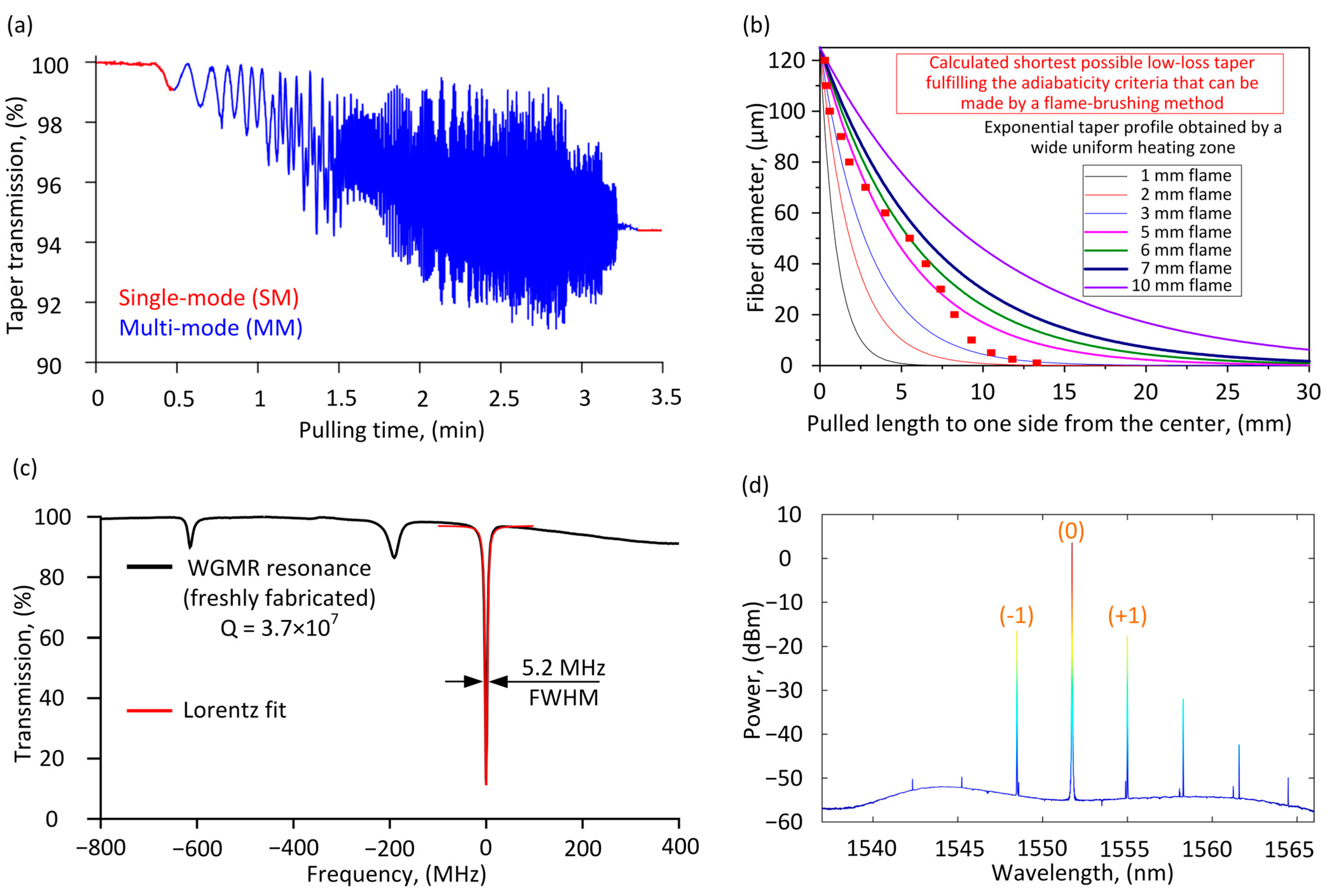
| Freshly fabricated | 0.13 | 2.1 | 5.2 | 3.7 × 10⁷ | 1.2 × 10⁸ | 3327 | 13.8 | yes |
| After 2 months | 0.64 | 9.0 | 15.7 | 1.2 × 10⁷ | 1.2 × 10⁸ | 1458 | 6.0 | yes |
| After 3.5 months | 0.62 | 8.4 | 50 | 3.9 × 10⁶ | 3.6 × 10⁷ | 455 | 1.9 | no |
| After 4 months | 0.78 | 16.1 | 96 | 2.0 × 10⁶ | 3.5 × 10⁷ | 249 | 1.0 | no |
| After 4 months (repaired by Hydrogen flame) | 0.74 | 13.3 | 44 | 4.4 × 10⁶ | 6.3 × 10⁷ | 538 | 2.2 | no |
Publisher’s Note: MDPI stays neutral with regard to jurisdictional claims in published maps and institutional affiliations. |
© 2022 by the authors. Licensee MDPI, Basel, Switzerland. This article is an open access article distributed under the terms and conditions of the Creative Commons Attribution (CC BY) license (https://creativecommons.org/licenses/by/4.0/).
Share and Cite
Salgals, T.; Alnis, J.; Ozolins, O.; Andrianov, A.V.; Anashkina, E.A.; Brice, I.; Berkis, R.; Pang, X.; Udalcovs, A.; Porins, J.; et al. Silica Microsphere WGMR-Based Kerr-OFC Light Source and Its Application for High-Speed IM/DD Short-Reach Optical Interconnects. Appl. Sci. 2022, 12, 4722. https://doi.org/10.3390/app12094722
Salgals T, Alnis J, Ozolins O, Andrianov AV, Anashkina EA, Brice I, Berkis R, Pang X, Udalcovs A, Porins J, et al. Silica Microsphere WGMR-Based Kerr-OFC Light Source and Its Application for High-Speed IM/DD Short-Reach Optical Interconnects. Applied Sciences. 2022; 12(9):4722. https://doi.org/10.3390/app12094722
Chicago/Turabian StyleSalgals, Toms, Janis Alnis, Oskars Ozolins, Alexey V. Andrianov, Elena A. Anashkina, Inga Brice, Roberts Berkis, Xiaodan Pang, Aleksejs Udalcovs, Jurgis Porins, and et al. 2022. "Silica Microsphere WGMR-Based Kerr-OFC Light Source and Its Application for High-Speed IM/DD Short-Reach Optical Interconnects" Applied Sciences 12, no. 9: 4722. https://doi.org/10.3390/app12094722