Article

Analytical Solution on Ground Deformation Caused by Parallel Construction of Rectangular Pipe Jacking

1
Key Laboratory for Urban Underground Engineering of Ministry of Education, Beijing Jiaotong University, Beijing 100044, China
2
Liaoning Key Laboratory of Marine Environmental Bridge and Tunnel Engineering, Dalian Maritime University, Dalian 116026, China
3
Beijing Urban Construction Design & Development Group Co., Ltd., Beijing 100037, China
*
Author to whom correspondence should be addressed.
Appl. Sci. 2022, 12(7), 3298; https://doi.org/10.3390/app12073298
Submission received: 22 February 2022 / Revised: 16 March 2022 / Accepted: 22 March 2022 / Published: 24 March 2022
(This article belongs to the Topic Engineering Mathematics)

Abstract

:
Pipe jacking has been widely used in urban underground engineering construction in recent years. Prediction of ground deformation caused by pipe jacking is particularly important for the safety of construction. With regard to the densely arranged pipes used in the pipe roof structure method, an analytical model of stratum disturbance caused by jacking of parallel rectangular pipes is proposed on the basis of Mindlin’s displacement solution and the stochastic medium theory. The influencing factors such as soil loss, additional thrust on the excavation face, friction between pipe jacking machine and soil, friction between subsequent pipes and soil, and the grouting pressure were comprehensively considered. Then, a 3D numerical simulation and a case study were conducted. The results showed consistent agreement with the analytical solution, and the proposed method can take into account the asymmetry of surface settlement curve induced by construction. A discussion of the ground deformation law shows that the proposed approach can reasonably predict the ground deformation and provide a reference for relevant pipe jacking construction.

1. Introduction

Urban underground space is becoming increasingly crowded with the development and expansion of cities, and the open-cut construction method has gradually been unable to meet the needs of many urban underground engineering constructions. Pipe jacking is a common trenchless construction method, which has been widely used in the construction of sewers, pressurized pipelines, electricity lines, tunnels, etc. [1,2,3]. For the purpose of coping with the complex construction environment, the pipe roof method is applied to the construction of crossing roads, railways, bridges, buildings, and other adjacent structures [4,5]. On the basis of the pipe jacking method and pipe roof method, the pipe roof structure method came into being, which is also known as the new pipe roof method or pipe roof preconstruction method [6,7,8,9].
The pipe roof structure method originated from the construction of the Antwerp subway station in Belgium, Europe [10,11]. Since then, Korean engineers improved this method through the application of several projects in South Korea [12,13]. When the Xinleyizhi station of Shenyang Metro Line 2 was built, the pipe roof structure method was used for the first time in China to build the main structure and the air conduit. Subsequently, this construction method was applied to the construction of Taiyuan Railway Station’s north–south tunnel project under Yingze Street in Taiyuan City, Shanxi province. Today, the pipe roof structure method is also being adopted for the tunnel crossing project of the Yifeng Gate in Nanjing. As shown in Figure 1, close-packed large-diameter pipes are driven into established positions in the pipe roof working shaft. Then, the permanent reinforced concrete structure is formed in the pipes after the cutting of pipes and installation of steel bars. The pipe jacking process during pipe roof structure construction is a key construction step that needs to be investigated systematically.
Scholars have carried out extensive research on the pipe roof structure method through in situ testing, laboratory testing, analytical calculation, and numerical simulation, and some inspiring results have been proposed. On the basis of the construction of Xinleyizhi station project and the soil arch theory, Yang et al. [14] deduced the relationship between the bearing constraint force of the arch axis and the geometric parameters of the model. Combined with the strength control condition of the vault and the arch footing, the equations for calculating pipe spacing could be obtained. At the same time, the whole construction process was monitored to ensure safety. It turned out that the maximum deformation occurred during the jacking of the layer 1–7 pipe, and the traditional Peck method was no longer applicable for this case. Hence, a modified Peck formula was proposed for the prediction of surface settlement during pipe jacking, and the results were in good agreement with the in situ monitoring data [10]. In order to study the mechanical response of tunnel lining and the ground surface subsidence during the excavation with the pipe roof structure method, Li et al. [15] conducted several field tests and numerical simulations for the relevant projects. The simulation results were consistent with the monitoring data, and the surface subsidence value was quite equal to the foundation. Compared with other construction methods, the pipe roof structure method can effectively reduce the ground surface subsidence, which is suitable for urban underground traffic construction projects. The tunnel crossing project of the Taiyuan Railway Station with the pipe roof structure method used 20 steel pipes, and the distance between these pipes was less than 165–265 mm. On the basis of this project, Yang et al. [16] studied the jacking force of densely arranged pipes using a large-scale similar model test combined with engineering measured data. A pipe soil arching effect was formed during the construction of these pipes, thus causing a reduction in the jacking force. The modified formula could be used to predict the jacking force more accurately. Unlike the traditional pipes used in pipe roof construction, pipes with flanges have recently been developed and applied in engineering. In this construction method, the adjacent steel pipes are connected by flange plates, which can effectively increase the stiffness and bearing capacity of the structure [8]. Considering factors such as the pipe soil interaction, distribution of pipe soil friction, and supporting pressure of excavation face, Jia et al. [17] studied the stratum deformation caused by pipe jacking with flanges. According to Mindlin’s solution and the stochastic medium theory, a formula for predicting the settlement caused by pipe jacking with flanges was proposed. The effectiveness of the formula was demonstrated by comparing the ground subsidence monitoring data with the theoretical calculation results.
It is obvious that the development of the ground surface settlement is of great significance during the construction of the underground pipe roof structure, especially in the process of pipe jacking construction. At present, the prediction methods of stratum deformation caused by the construction of tunnels mainly include the empirical formula method [18,19], theoretical analysis [20,21,22], numerical simulation [23], laboratory model test [24], and in situ monitoring [8]. Among them, the Peck empirical formula [18] was the first and most widely used method. However, it cannot take into account the influence of shallow burying and shape of the tunnel cross-section. Then, the stochastic medium method [25] was proposed, which can effectively make up for these deficiencies. The complex variable method [26,27] can simplify the complex problems in the physical plane to facilitate the solution of the problem; thus, it was introduced into the field of underground engineering by scholars to predict the ground settlement [28,29]. In addition, there are the virtual image technique [20], stress function analytical solution [21], and Mindlin’s solution [30], where Mindlin’s solution can consider the influence of the construction process on stratum deformation, which makes it a suitable and fast prediction method. The pipe roof structure method can effectively control the development of ground settlement in urban underground engineering construction. However, until now, there has seldom been research on the stratum deformation caused by this construction method.
In view of close-packed rectangular pipe jacking construction using the pipe roof structure method, considering the soil loss, additional thrust at the excavation face, friction force of the pipes and jacking machine, and grouting pressure, an analytical solution is proposed to calculate the ground deformation induced by parallel jacked rectangular pipes using Mindlin’s solution and the stochastic medium theory. A numerical simulation model was established, and the simulation results were compared with the predictions using the proposed method.

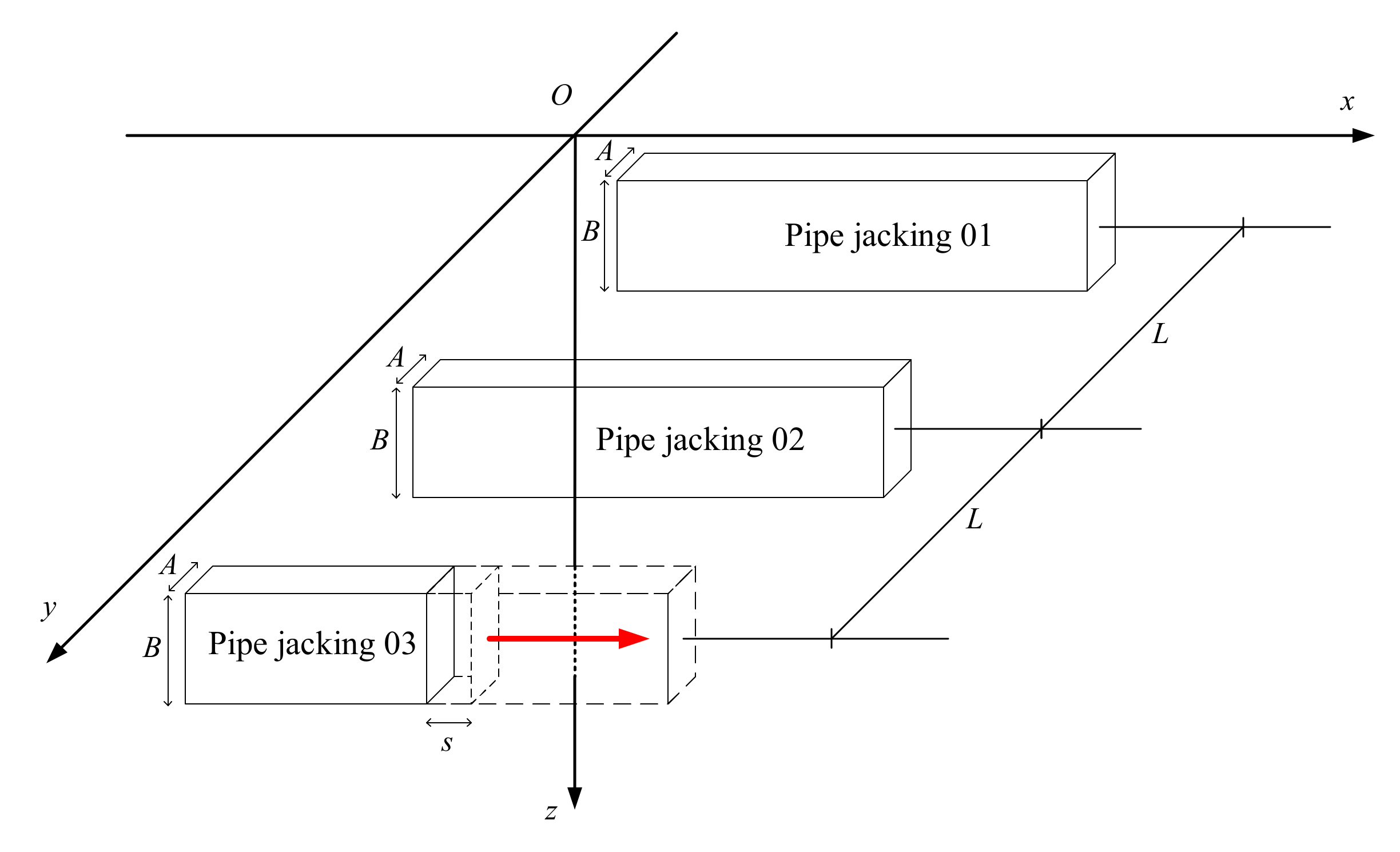
2. Calculation Model and Basic Assumptions

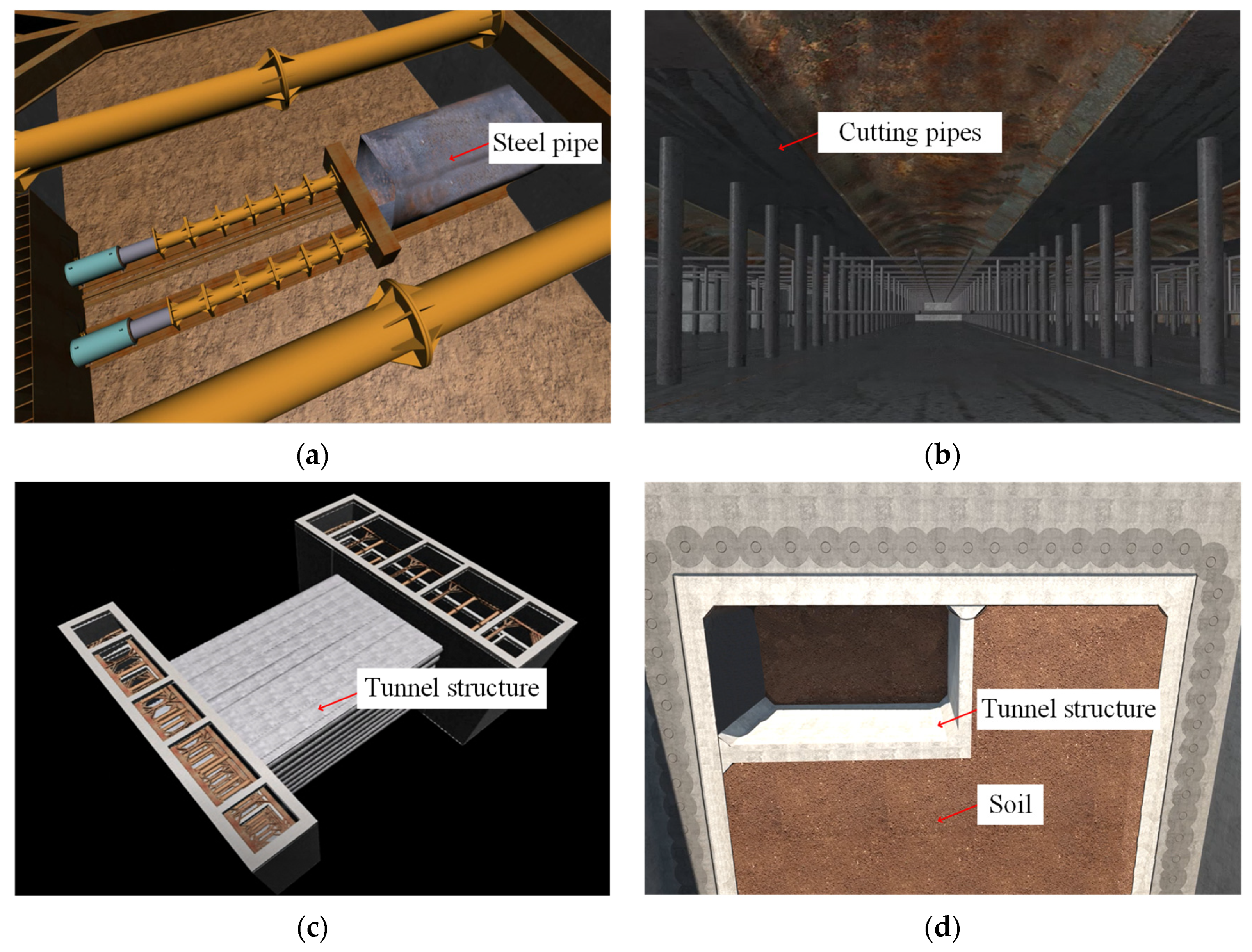
2.1. Basic Assumptions of Rectangular Pipe Jacking Construction

The main factors causing displacement and deformation of the surrounding stratum during rectangular pipe jacking construction include additional thrust at the excavation face, friction between pipe jacking machine and surrounding soil, friction between subsequent pipe and surrounding soil, additional grouting pressure, and soil loss [1,17]. In the process of analytical calculation, the model includes five basic assumptions [31,32]: (1) the stratum is homogeneous elastic half-space, which has been consolidated under the undrained condition; (2) the pipe jacking machine is along a straight line, regardless of the influence of rectification and tilt of the jacking machine; (3) during the construction process, the pipe jacking machine only changes position in space, without considering the time effect; (4) the supporting force of the excavation face and the friction between the pipe jacking machine, pipe, and soil are uniformly distributed; (5) the factors affecting the stratum deformation are relatively independent, without considering their interaction.
Due to the complexity of the construction process, the superposition method was adopted to simplify the calculation. The stratum settlement caused by various factors could be calculated separately and then superimposed. The friction of jacking machine and subsequent pipes can be divided into four parts: top surface, bottom surface, left side, and right side. The thrust at the tunnel face, frictions, and grouting pressure act on an infinite body in half space, resulting in internal deformation, which can be calculated by Mindlin’s solution.

2.2. Mindlin’s Solution

From Mindlin’s displacement solution of homogeneous elastic half-space [30,32], it can be seen that, when a concentrated load along the x-axis acts at the point (ξ, ζ, η) in the semi-infinite space, the vertical displacement at (x, y, z) can be expressed by
w x ξ , ζ , η = x ξ 16 π G 1 μ z η M 3 + 3 4 μ z η N 3 6 z η z + η N 5 + 4 1 μ 1 2 μ N N + z + η ,
where G = Es (1 − 2μ)/2 (1 + μ) is the shear modulus of the soil, Es is the compression modulus of the soil, and μ is the Poisson’s ratio of the soil. M and N are the distance between the action point of the concentrated load and its symmetry to the calculated point respectively.
M = x ξ 2 + y ζ 2 + z η 2 ,
N = x ξ 2 + y ζ 2 + z + η 2 .
Similarly, the displacement caused by the concentrated unit load along the y-axis at (x, y, z) can be expressed as
w y ξ , ζ , η = y ζ 16 π G 1 μ z η M 3 + 3 4 μ z η N 3 6 z η z + η N 5 + 4 1 μ 1 2 μ N N + z + η .
The displacement caused by the concentrated unit load along the z-axis at (x, y, z) can be expressed as
w z ξ , ζ , η = 1 16 π G 1 μ 3 4 μ M + 8 1 μ 2 3 4 μ N + z η 2 M 3 + 3 4 μ z η 2 2 z η N 3 + 6 z η z + η 2 N 5 .

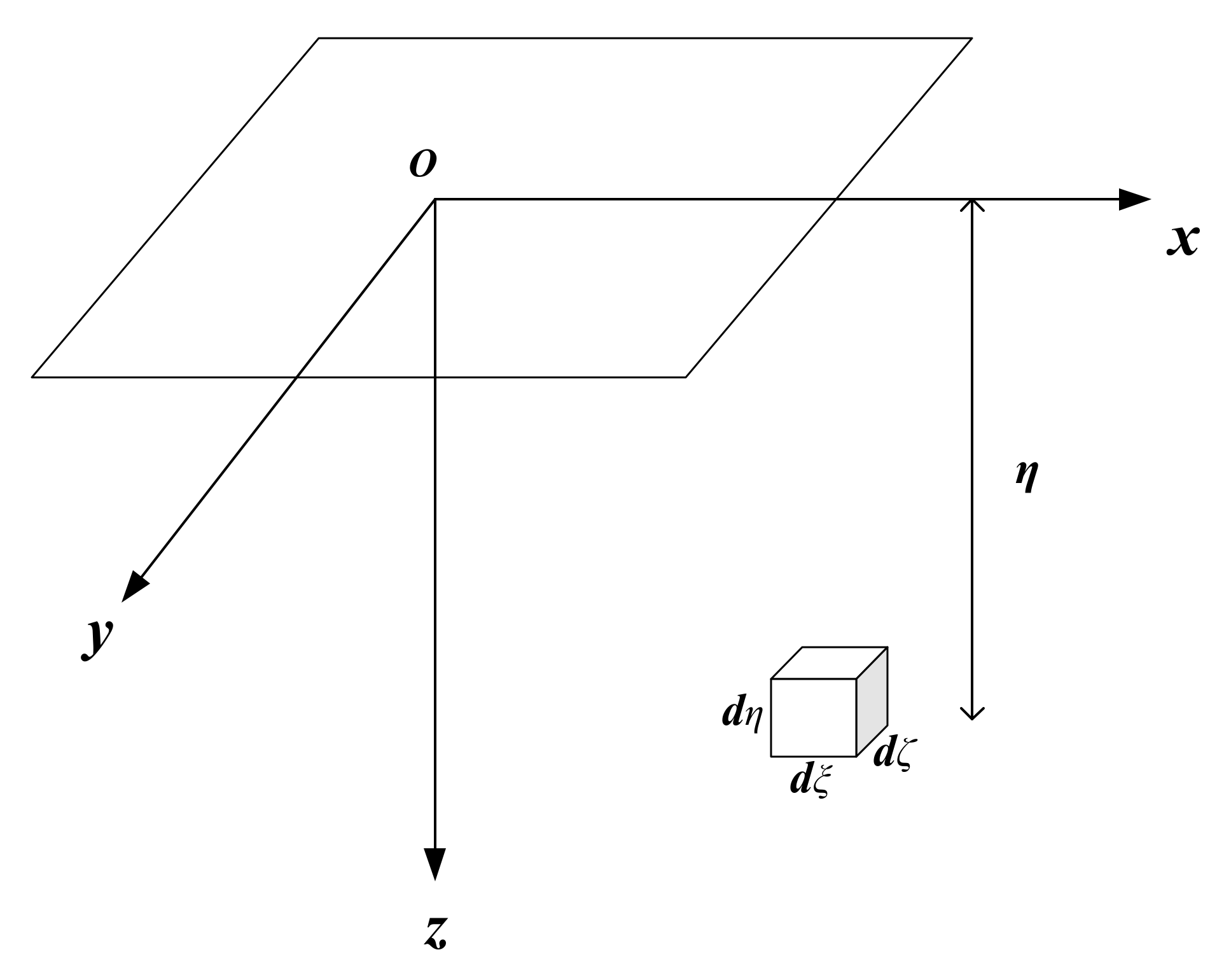
2.3. Stochastic Medium Theory

For the calculation method of surface settlement caused by soil loss, the Peck formula cannot consider the influence of the tunnel cross-section shape on settlement trough [18]. At present, it is suitable for tunnels with large buried depth, but not for ultra-shallow buried tunnels. Therefore, this paper aimed to use stochastic medium theory to calculate the ground settlement caused by soil loss.
The stochastic medium theory was proposed by Litwiniszyn [33] through a test in a sandbox, and it was then applied by Liu [34] to predict the ground surface displacement caused by tunnel construction and mining engineering. The stochastic medium theory regards rock and soil as a stochastic medium and the stratum displacement caused by underground engineering excavation as a stochastic process. Therefore, ground subsidence can be regarded as the sum of deformation caused by the complete collapse of several units.
As shown in Figure 2, the settlement of the upper soil (x, y, z) caused by the complete collapse of a homogeneous infinitesimal excavation unit under undrained consolidation condition can be written as follows [35]:
w = tan β 2 η z 2 exp π tan β 2 η z 2 x ξ 2 + y ζ 2 d ξ d ζ d η ,
where η is the distance between the excavation unit and the surface, and β is the main influence angle of the upper stratum.

3. Vertical Displacement of Stratum Caused by Parallel Pipe Jacking Construction

Figure 3 shows a schematic diagram of the mechanical calculation. It is assumed that the pipe jackings 01 and 02 of the left line have been completed, the construction of the right line 03 is not completed, and the pipe jacking machine’s excavation face is located in the x = 0 plane. Therefore, the stratum deformation caused by pipe jackings 01 and 02 only includes soil loss. For the stratum deformation caused by pipe jacking 03, we should comprehensively consider the influence of the additional thrust at the excavation face, friction between pipe jacking machine and soil, friction between subsequent pipe and soil, drag reduction by thixotropic fluids, compensation grouting of subsequent pipe, and soil loss.

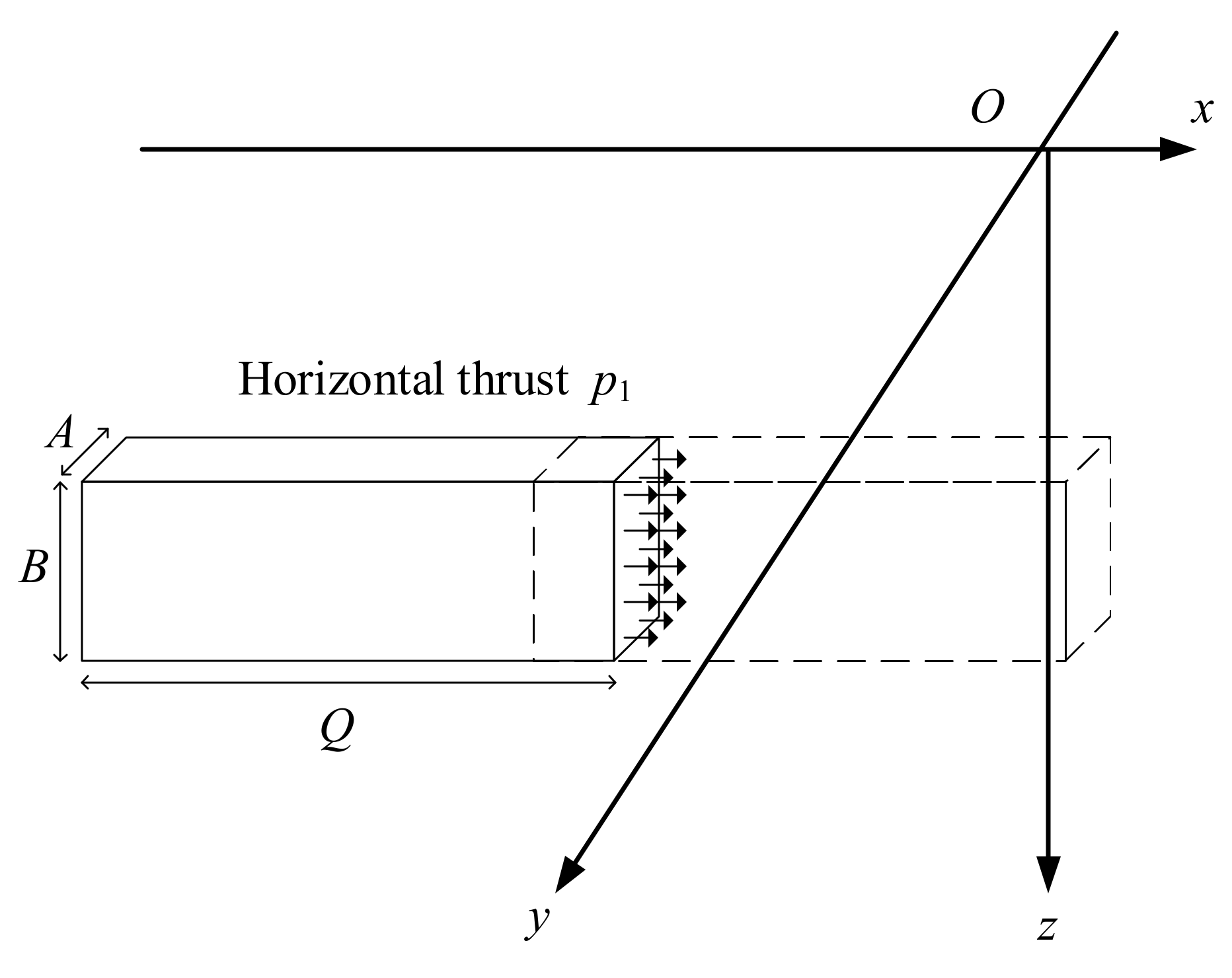
3.1. Settlement Induced by Additional Horizontal Thrust at Excavation Face

According to previous research [1], the additional horizontal thrust at the excavation face is generally controlled at ±20 kPa to ensure that the pipe jacking construction has little impact on the surrounding strata and buildings.
As shown in Figure 4, the additional horizontal thrust per unit area of excavation face during jacking construction of a pipe jacking machine is p1dζdη. By integrating Equation (1), the vertical displacement w1 caused by the additional horizontal thrust on the excavation surface can be obtained as
w 1 = p 1 D w x ξ , ζ , η d ζ d η ,
where A and B are the width and height of the pipe jacking machine, respectively. H is the axial depth of the pipe jacking machine, and p1 is the additional horizontal thrust of the excavation face.

3.2. Settlement Induced by Friction of the Pipe Jacking Machine

The friction in pipe jacking construction is the normal stress multiplied by the friction coefficient. For the convenience of calculation, the active earth pressure at the axis can be taken as the normal stress.
(1) Top of pipe jacking machine
As shown in Figure 5, the friction per unit area on the top surface of the pipe jacking machine during jacking is p2udξdζ. The vertical displacement of the point (x, y, z) in the soil is w2u under the action of friction on the top of the pipe jacking machine.
w 2 u = p 2 u D w x ξ , ζ , η d ξ d ζ ,
where L is the length of pipe jacking machine, and p2u is the friction between the top surface of the pipe jacking machine and the soil.
(2) Bottom of pipe jacking machine
The friction per unit area at the bottom surface (Figure 5) of the pipe jacking machine during jacking is p2ddξdζ. The vertical displacement of the point (x, y, z) in the soil is w2d under the action of friction at the bottom of the pipe jacking machine.
w 2 d = p 2 d D w x ξ , ζ , η d ξ d ζ ,
where p2d is the friction between the bottom surface of the pipe jacking machine and the soil.
(3) Left side of pipe jacking machine
The friction per unit area on the left side (Figure 5) of the pipe jacking machine during jacking is p2ldξdζ. The vertical displacement of the point (x, y, z) in the soil is w2l under the action of friction on the left side of the pipe jacking machine.
w 2 l = p 2 l D w x ξ , ζ , η d ξ d η ,
where p2l is the friction between the left side of the pipe jacking machine and the soil.
(4) Right side of pipe jacking machine
The friction per unit area on the right side (Figure 5) of the pipe jacking machine during jacking is p2rdξdζ. The vertical displacement of the point (x, y, z) in the soil is w2r under the action of friction on the right side of the pipe jacking machine.
w 2 r = p 2 r D w x ξ , ζ , η d ξ d η ,
where p2r is the friction between the right side of pipe jacking machine and the soil.

3.3. Settlement Induced by Friction of the Pipe Jacking

During the pipe jacking construction, the pipe jacking machine is in close contact with the soil, but there is a layer of thixotropic fluids between the subsequent pipe and the surrounding soil [36,37]. Therefore, the drag reduction effect of slurry sleeve should be considered in the subsequent pipes. In this paper, the friction between the pipe and soil is 0.5 times the friction between the pipe jacking machine and soil.
(1) Top of subsequent pipe jacking
As shown in Figure 6, the friction per unit area on the top surface of the subsequent pipe during jacking is p3udξdζ. Under the action of the friction on the top of the pipe, the vertical displacement w3u of the point (x, y, z) in the soil can be calculated as
w 3 u = p 3 u D w x ξ , ζ , η d ξ d ζ ,
where p3u is the friction between the top surface of the pipe and the soil.
(2) Bottom of subsequent pipe jacking
The friction per unit area at the bottom surface (Figure 6) of the subsequent pipe during jacking is p3ddξdζ. Under the action of the friction at the bottom of the pipe, the vertical displacement w3d of the point (x, y, z) in the soil can be calculated as
w 3 d = p 3 d D w x ξ , ζ , η d ξ d ζ ,
where p3d is the friction between the bottom surface of the pipe and the soil.
(3) Left side of subsequent pipe jacking
The friction per unit area on the left side (Figure 6) of the subsequent pipe during jacking is p3ldξdζ. Under the action of the friction on the left side of the pipe, the vertical displacement w3l of the point (x, y, z) in the soil can be calculated as
w 3 l = p 3 l D w x ξ , ζ , η d ξ d η ,
where p3l is the friction between the left side of the pipe and the soil.
(4) Right side of subsequent pipe jacking
The friction per unit area on the right side (Figure 6) of the subsequent pipe during jacking is p3rdξdζ. Under the action of the friction on the right side of the pipe, the vertical displacement w3r of the point (x, y, z) in the soil can be calculated as
w 3 r = p 3 r D w x ξ , ζ , η d ξ d η ,
where p3r is the friction between the right side of the pipe and the soil.

3.4. Settlement Induced by Grouting Pressure

After the jacking construction, the thixotropic fluids should be replaced in time to control stratum deformation. Usually, even for long-distance pipe jacking, the grouting pressure is controlled below 1 MPa because higher grouting pressure will cause greater jacking force. In this paper, the synchronous grouting pressure is added at 20 kPa on the basis of the water and earth pressure at the position of the pipe roof [3].
(1) Top of subsequent pipe jacking
As shown in Figure 7, the additional grouting pressure per unit area on the top surface of the subsequent pipe during jacking is p4udξdζ. Under the action of the additional grouting pressure on the top surface of the pipe, the vertical displacement w4u of the point (x, y, z) in the soil can be calculated as
w 4 u = p 4 u D w z ξ , ζ , η d ξ d ζ ,
where p4r is the additional grouting pressure between the top surface of the pipe and the soil.
(2) Bottom of subsequent pipe jacking
The additional grouting pressure per unit area at the bottom of the subsequent pipe (Figure 7) during jacking is p4ddξdζ. Under the action of the additional grouting pressure on the bottom of the pipe, the vertical displacement w4d of the point (x, y, z) in the soil can be calculated as
w 4 d = p 4 d D w z ξ , ζ , η d ξ d ζ ,
where p4d is the additional grouting pressure between the bottom of the pipe and the soil.
(3) Left side of subsequent pipe jacking
The additional grouting pressure per unit area on the left side (Figure 7) of the subsequent pipe during jacking is p4ldξdζ. Under the action of the additional grouting pressure on the left side of the pipe, the vertical displacement w4l of the point (x, y, z) in the soil can be calculated as
w 4 l = p 4 l D w y ξ , ζ , η d ξ d η ,
where p4l is the additional grouting pressure between the left side of the pipe and the soil.
(4) Right side of subsequent pipe jacking
The additional grouting pressure per unit area on the right side (Figure 7) of the subsequent pipe during jacking is p4rdξdζ. Under the action of the additional grouting pressure on the right side of the pipe, the vertical displacement w4r of the point (x, y, z) in the soil can be calculated as
w 4 r = p 4 r D w y ξ , ζ , η d ξ d η ,
where p4r is the additional grouting pressure between the right side of the pipe and the soil.

3.5. Settlement Induced by Soil Loss

3.5.1. Convergence Mode of the Excavation Face

In the process of pipe jacking construction, the surrounding soil will converge to the position of the pipe due to disturbance. The traditional convergence model proposes that the soil will converge uniformly to the center of the pipe. However, the weight of the pipe is often larger than that of the soil. Therefore, the convergence model of the pipe falling on the soil surface was adopted in this paper [31], as illustrated in Figure 8.
Let the convergence value of the cross section ∆t = ∆A = ∆B and ignore the area of the four corners; then, the following can be obtained:
4 A Δ t + 4 B Δ t = S κ ,
Δ t = S κ 4 A + B ,
where κ is the ground loss ratio, and S is the area of the cross-section.
According to the existing construction experience [3], the soil loss rate is usually 0.5–2.5% for cohesive soil. With the improvement of construction technology, the ground loss ratio can generally be effectively controlled at less than 1.8%.

3.5.2. The Main Influence Angle

Han and Li [38] proposed that the main influence angle β in the stochastic medium theory has the same effect as the settlement trough width coefficient K in the Peck formula. According to the correlation between these two parameters, the following can be reached:
tan β = z 0 2 π i .
Taking i = Kz0 in the soil strata,
tan β = 1 2 π K ,
where K is the settlement trough width coefficient, which can be described by a linear equation with the internal friction angle of soil [39].
K = 1 0.02 φ .
The following formula can be obtained:
tan β = 20 50 φ .
The above formula considers the influence of tunnel construction and soil conditions, where β can be obtained and corrected through back analysis using the field monitoring date of the engineering test section or the previously constructed pipe, so as to guide the subsequent construction. According to the research of Wei et al. [40], this paper takes the stratum influence angle βs = 0.85β for the subsequent pipe jacking construction considering the influence of the constructed pipe on the stratum.

3.5.3. Ground Surface Settlement

It is assumed that the construction of pipes 01 and 02 has already been completed, and the excavation face of the pipe jacking machine 03 is located in the plane of x = 0.
(1) Pipe jackings 01 and 02 completed in advance
The integral range is presented in Figure 8b. The integral interval for excavation section Ω takes (−Q, Q) in the ξ axis direction. The integral interval for excavation section ω takes (−Q, Q) in the ξ axis direction. The vertical displacement w5l of the point (x, y, z) in stratum caused by soil loss during jacking construction of the left line can be obtained as
w 5 l = Q Q Ω ω tan β 2 z η 2 exp π tan β 2 z η 2 x ξ 2 + y ζ 2 d ξ d ζ d η .
(2) Pipe jacking 03 for subsequent jacking construction
The integral interval for excavation section Ω takes (−Q, 0) in the ξ axis direction. The integral interval for excavation section ω takes (−Q, 0) in the ξ axis direction (Figure 9). The vertical displacement w5r of the point (x, y, z) in stratum caused by soil loss during jacking construction of the left line can be obtained as
w 5 r = Q 0 Ω ω tan β 2 z η 2 exp π tan β 2 z η 2 x ξ 2 + y ζ 2 d ξ d ζ d η .

3.6. Calculation of Total Ground Settlement

The calculation formula of total vertical displacement w can be obtained by superposition of the vertical displacement caused by various factors in pipe jacking construction.
w = w 1 + w 2 + w 3 + w 4 + w 5 .

4. Verification of the Analytical Solution

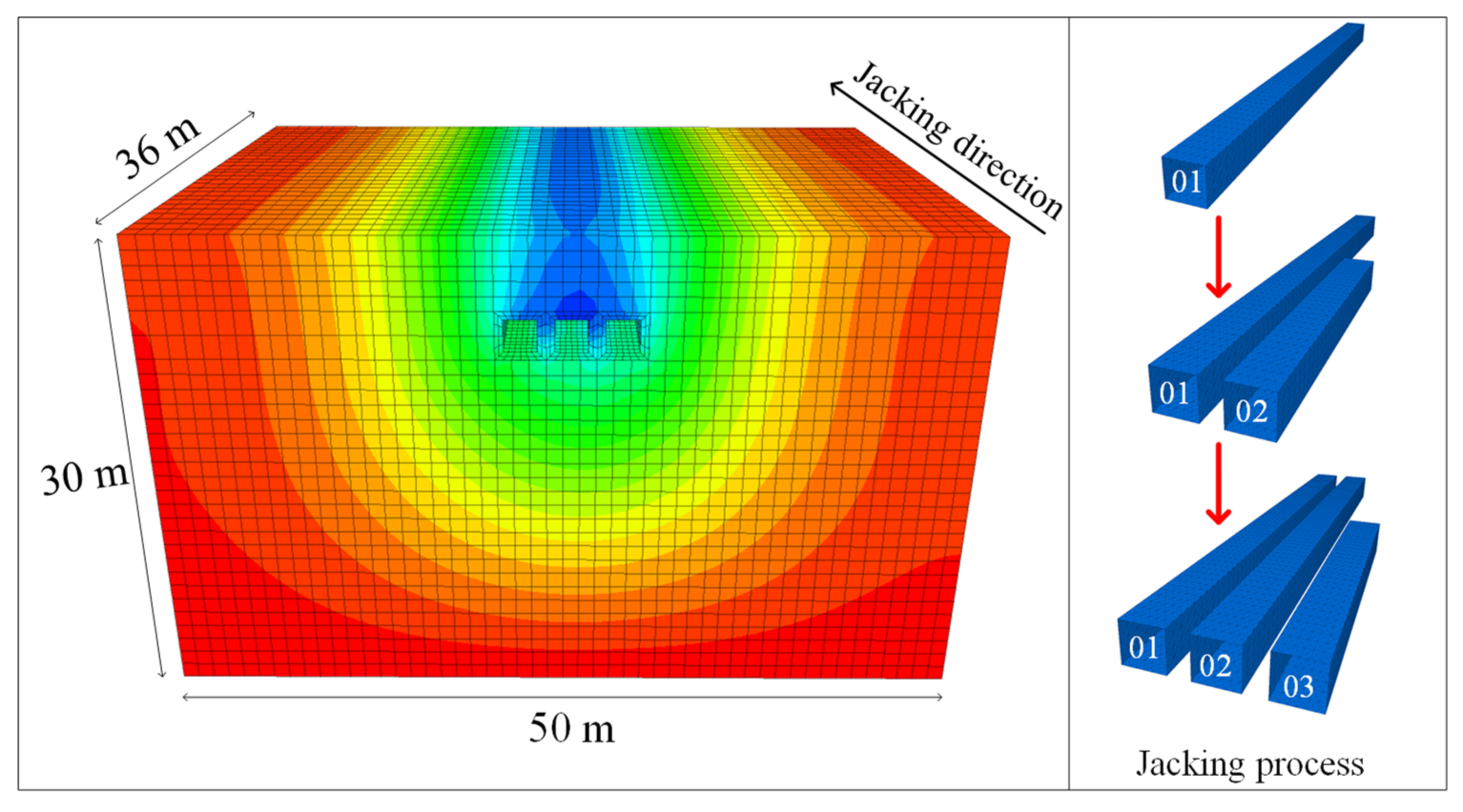
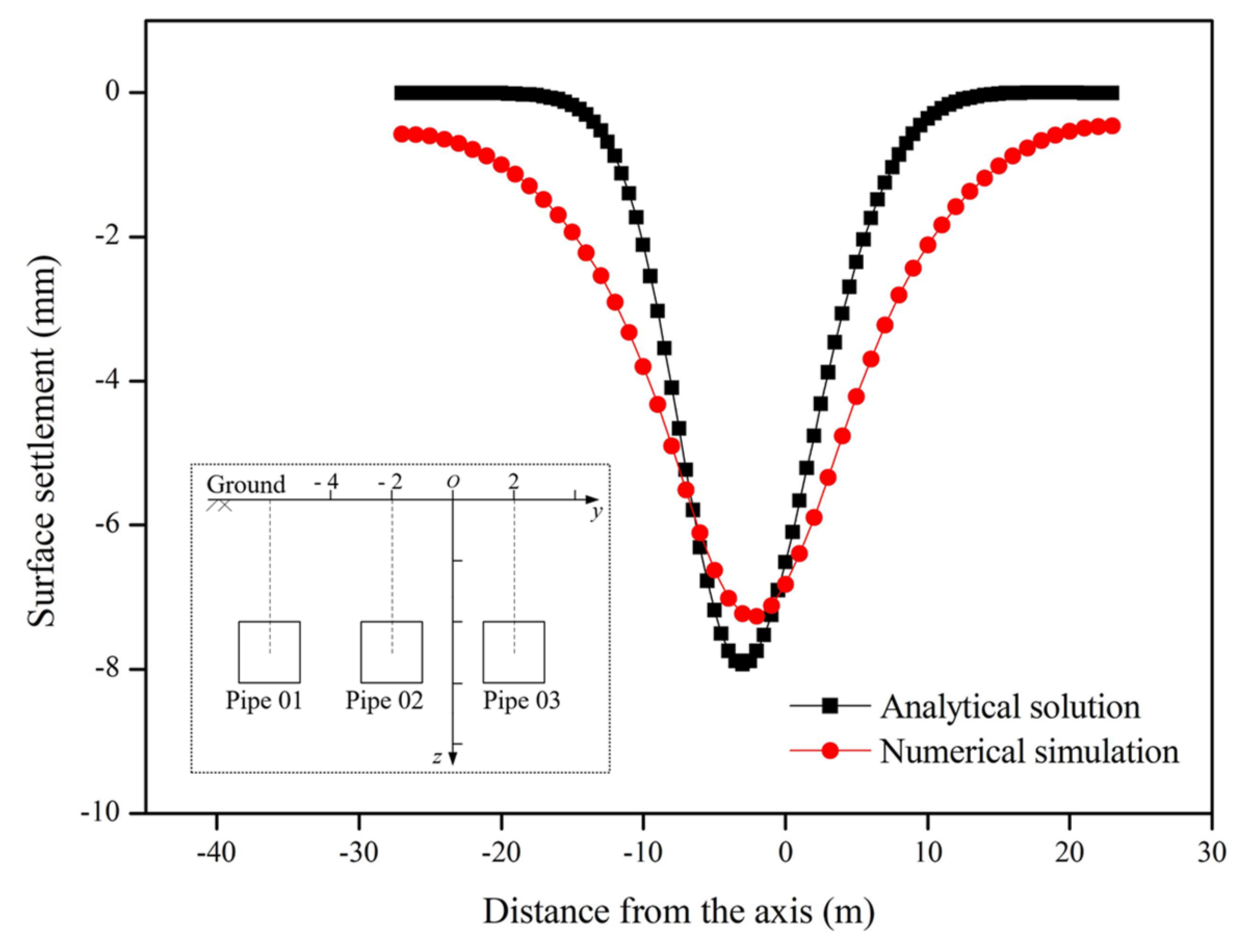
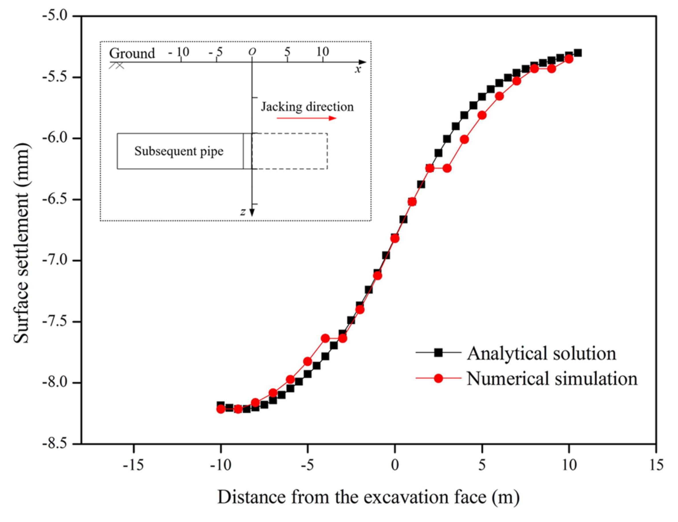
4.1. Numerical Verification of the Analytical Solution

The finite difference software FLAC3D was used to simulate the jacking construction of rectangular pipes. The stratum deformation caused by time effect was not considered during the construction of pipe jacking. Moreover, the deformation and deformation rate under initial gravity stress were not considered. In the actual construction process, each pipe section is rigidly connected by welding; hence, the shell element can be used to simulate the overall steel pipe jacking.
The selection of the numerical simulation model should fully consider the influence range of the analytical solution. In this paper, the size of the numerical simulation model was 50 m in width and 30 m in depth, and the longitudinal excavation length was 36 m. The lateral distance between the pipe and the model boundary was greater than five times the pipe width, which could eliminate the influence of the model boundary on the calculation results. For the boundary of the numerical model, the upper face took z = −30 m as the free boundary, and the bottom face was constrained in the z-direction at z = −30 m. The left and right sides were constrained in the x-direction at the positions x = −27 m and x = 23 m. The front and rear sides were constrained in the y-direction at the positions y = 0 m and y = 36 m.
The isotropic elastic–plastic model was adopted for the soil, and the yield criterion was the Mohr–Coulomb criterion. Assuming that the soil layers were evenly and horizontally distributed. The thickness of the pipe wall was much smaller than the section size of the pipe; thus, the steel pipe can be regarded as a thin-walled tube. In the comparative calculation, the sizes of the pipe section were A = 2 m and B = 2 m. The length of the pipe jacking machine was s = 2 m. The distance between the axial of the pipe and the ground was H = 5 m. The axial distance between the pipes was L = 3 m. The additional thrust, friction, and grouting pressure were 20 kPa, 5 kPa, and 20 kPa, respectively. The calculation model is presented in Figure 9.
Firstly, under the action of gravity, the initial stress field of the model was balanced, and then the displacement was cleared to obtain the stress field of the unexcavated state before construction. Secondly, the unbalanced force of the outer node of the excavation unit was obtained by excavating the first unit and running a calculation. The unbalanced force on these nodes was multiplied by a coefficient less than 1 and reversely applied to the corresponding nodes. In this paper, the stress release rate was 15% to simulate the stress release in the construction process. Then, a uniform load was applied on the excavation face to simulate the additional horizontal thrust of the pipe jacking machine. The shell structure unit was added to simulate the corresponding pipe, and then the calculation process was started to balance the stress in the model. Lastly, 3.6 m was taken as the cycle of excavation step, and excavation continued until the pipe jacking construction was complete.
(1) Comparison of transverse surface settlement
The working condition where the left pipes 01 and 02 were completed while the right pipe was jacked for 18 m was taken as an example (i.e., the excavation face of jacking machine 03 was located at the position of x = 0). The lateral settlement curves of the ground surface obtained by analytical calculation and numerical simulation are shown in Figure 10.
The analytical calculation results of the transverse surface settlement curve are consistent with the overall trend of numerical simulation results. With the monitoring points away from the axis of the pipe, the ground surface settlement gradually decreased and tended to be stable, and the influence range was about five times the width of the pipe. The maximum settlements of the analytical calculation and numerical simulation results were 7.93 mm and 7.26 mm, respectively, and the difference between the two was about 8.45%. The position difference of the maximum settlement point was about 0.5 m.
(2) Comparison of longitudinal surface settlement
The working condition where the left pipes 01 and 02 were completed while the right pipe was jacked for 18 m was taken as an example (i.e., the excavation face of jacking machine 03 was located at the position of x = 0). The longitudinal settlement curve of the ground surfaces obtained by analytical calculation and numerical simulation are shown in Figure 11.
The analytical calculation results of the longitudinal settlement curve are consistent with the overall trend of numerical simulation results. The surface settlement value increased gradually with the construction of pipe jacking, and the deformation rate increased rapidly when the tunnel faces were passed. Then, the deformation rate decreased, and the settlement value tended to be stable after the excavation face passing away from the monitoring point. The maximum settlement values of the analytical and numerical simulation results were 8.21 mm and 8.24 mm, respectively, and the difference between them is relatively small.

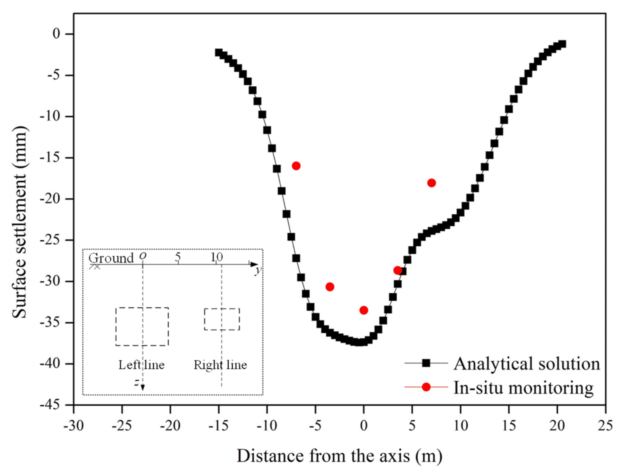
4.2. In Situ Monitoring Data Validation of the Analytical Solution

(1) Project overview
Zhongzhou Avenue is an important north–south expressway through the center of Zhengzhou City. Two rectangular pipe jacking machines with different sizes were used in the Zhongzhou Road undercrossing project to construct the left motorway and the right pedestrian channel. The cross-sectional sizes of the tunnel on the left and right lines were 7.5 m × 10.4 m and 4.2 m × 6.9 m, respectively. Detailed engineering information can be found in previous work [41]. In this paper, the monitoring section D59 was selected for analysis.
(2) Comparison of transverse ground surface settlement
The transverse settlement curves of the ground surface obtained by analytical calculation and the in situ monitoring data are shown in Figure 12.
As shown in Figure 12, the trend of calculated and monitored ground settlement was basically consistent. The maximum settlements of the analytical calculation and in situ monitoring results were 37.35 mm and 33.49 mm, respectively. At the same time, it can be found that the overall data of in situ monitoring were smaller than the values of analytical calculation, which is because the grouting compensation method was used in the construction to lift the stratum. Due to the different dimensions of the left and right tunnels, the final surface settlement curve was asymmetric, and the settlement in the right part was significantly lower than that on the left.

5. Analysis of Surface Subsidence Deformation Law

5.1. Transverse Surface Subsidence Deformation

The transverse settlement curve due to pipe jacking of pipes 01, 02, and 03 and the total surface subsidence are presented in Figure 13:
When the construction of pipes 01 and 02 was completed while pipe 03 was at the position of x = 0, the maximum settlements were 4.21 mm, 3.50 mm, and 1.21 mm, respectively. The maximum settlement was located at the position of each axis of the pipe. The total maximum settlement was 7.93 mm, which was located between pipes 01 and 02. The surface settlement trough caused by each pipe jacking construction was consistent, and the deformation decreased gradually from the axis of the pipe to both sides. The subsequent pipe had a lager influence range in the horizontal direction, while it caused a smaller value of settlement.

5.2. Longitudinal Surface Subsidence Deformation

The longitudinal settlement curves due to pipe jacking of pipes 01, 02, and 03 and the total surface subsidence are presented in Figure 14.
After the completion of jacking pipes 01 and 02, the settlements caused by construction above the axis of the pipe 03 tended to be stable, which were about 2.06 mm and 3.31 mm, respectively. Specifically, when the horizontal distance from pipe 03 increased by 2.5 m, the maximum settlement decreased by 37.8%. The maximum surface settlements caused by jacking of pipe 03 and the total settlement above the axis of pipe 03 were 2.87 mm and 8.21 mm, respectively, located far behind the excavation face. From the settlement curve of pipe 03, it can be concluded that the changing rate of the settlement near the excavation face was relatively rapid. The range of about 8 m (four times the pipe width) in front of the excavation face was the influence area of surface subsidence, and the surface was almost unaffected when it exceeded 8 m.

5.3. The Main Influence Angle

Under the condition that other parameters remain unchanged, the influence angles of the stratum during subsequent pipe jacking construction were taken as βs = β, βs = 0.9β, βs = 0.8β, βs = 0.7β, βs = 0.6β, βs = 0.5β, and βs = 0.4β. The transverse surface settlement curves and the variation of the maximum settlements with the influence angle are shown in Figure 15 and Figure 16:
As shown in Figure 15, with the influence angle decreasing from β to 0.4β, the transverse surface settlement curve became wide and shallow, and the maximum settlement value gradually changed from 7.87 mm to 6.00 mm, a reduction by 23.76%. The maximum settlement point gradually moved to the negative direction of the y-axis (the completion area of pipe jacking construction), and the settlement value and influence range of the right region of the transverse surface settlement curve increased significantly. It can be seen from the variation curve of the maximum settlement value in Figure 16 that the maximum surface settlement value increased with the increase in βs/β, and the two parameters approximately showed a nonlinear positive correlation.

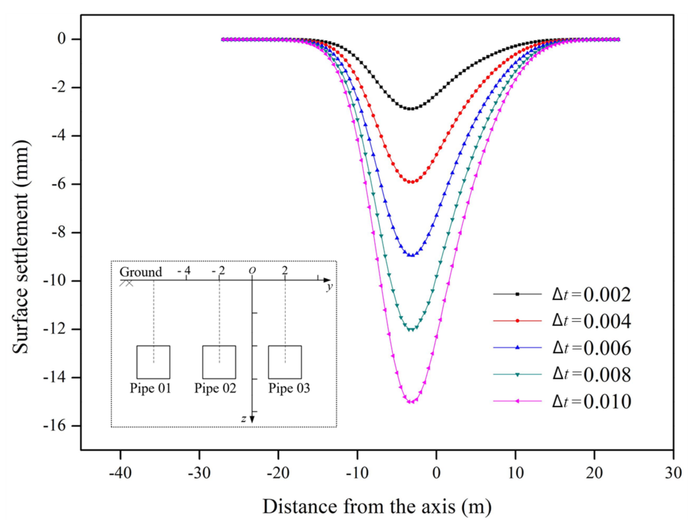
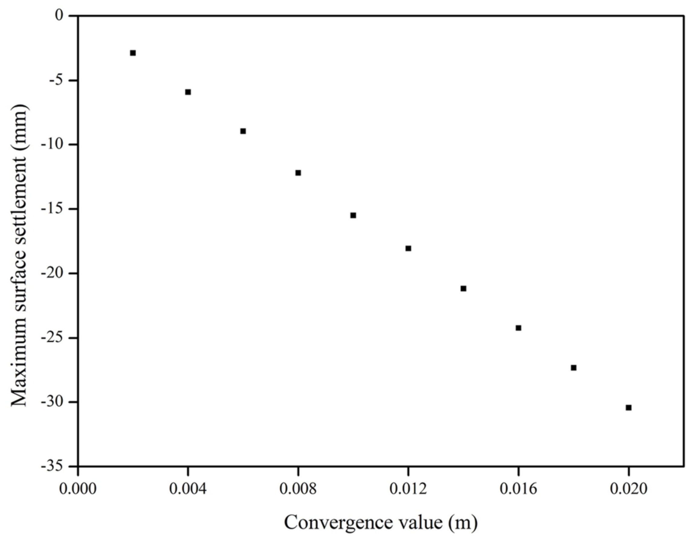
5.4. The Section Convergence Value

Under the condition that other parameters remain unchanged, the section convergence values of the pipes in subsequent construction were taken as 0.002 mm, 0.004 mm, 0.006 mm, 0.008 mm, and 0.01 mm. The longitudinal surface settlement curves and the variation of the maximum settlements with the convergence values are shown in Figure 17 and Figure 18:
As shown in Figure 17, the surface settlement curve caused by pipe jacking construction basically conformed with a normal distribution. The maximum settlement was located at the position of x = −3 m. With the increase in the distance from the monitoring point to the two sides of the axis of the pipes, the settlement value gradually decreased and tended to be stable. In the process of the convergence values changing from 10 mm to 2 mm, the maximum value of the transverse surface settlement curve gradually changed from 15.50 mm to 2.88 mm, a decrease by 81.42%. It can be seen from the variation curve of the maximum settlement values in Figure 18 that the maximum settlement value of the surface increased with the increase in convergence values, and the two parameters approximately showed a linear positive correlation.

6. Conclusions

This paper presented an analytical solution for predicting the ground deformation caused by jacking construction of parallel rectangular pipes. On the basis of Mindlin’s solution and the Stochastic medium theory, the main factors causing ground deformation were considered, including soil loss, additional thrust, friction force, and grouting pressure. A three-dimensional numerical simulation and case study were carried out to verify the effectiveness of the analytical model. the ground deformation law and relevant parameters were discussed. The following conclusions can be drawn:
(1)
A comparison of the numerical simulation and engineering case study showed that the proposed method can successfully predict ground surface settlement. In addition, this method can also take into account the asymmetry of the settlement curve caused by different construction sequences.
(2)
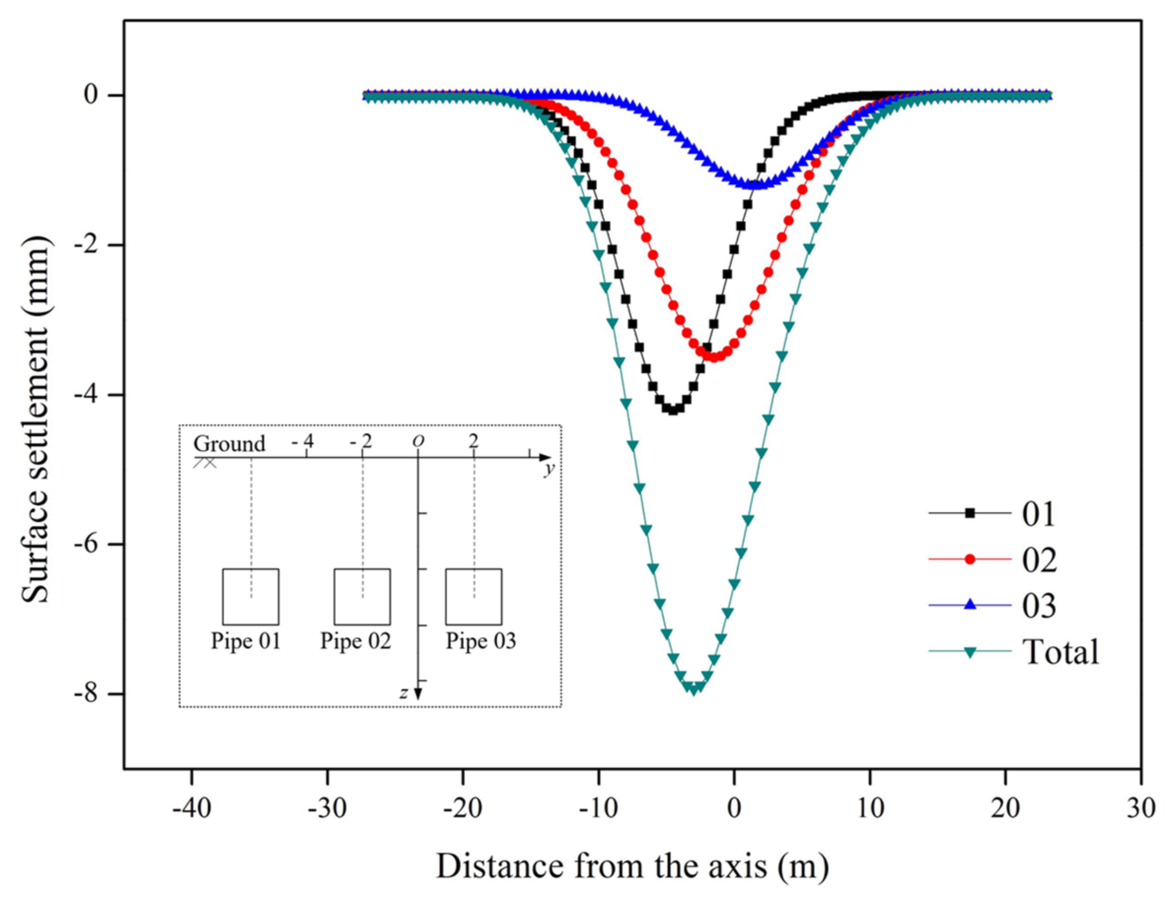
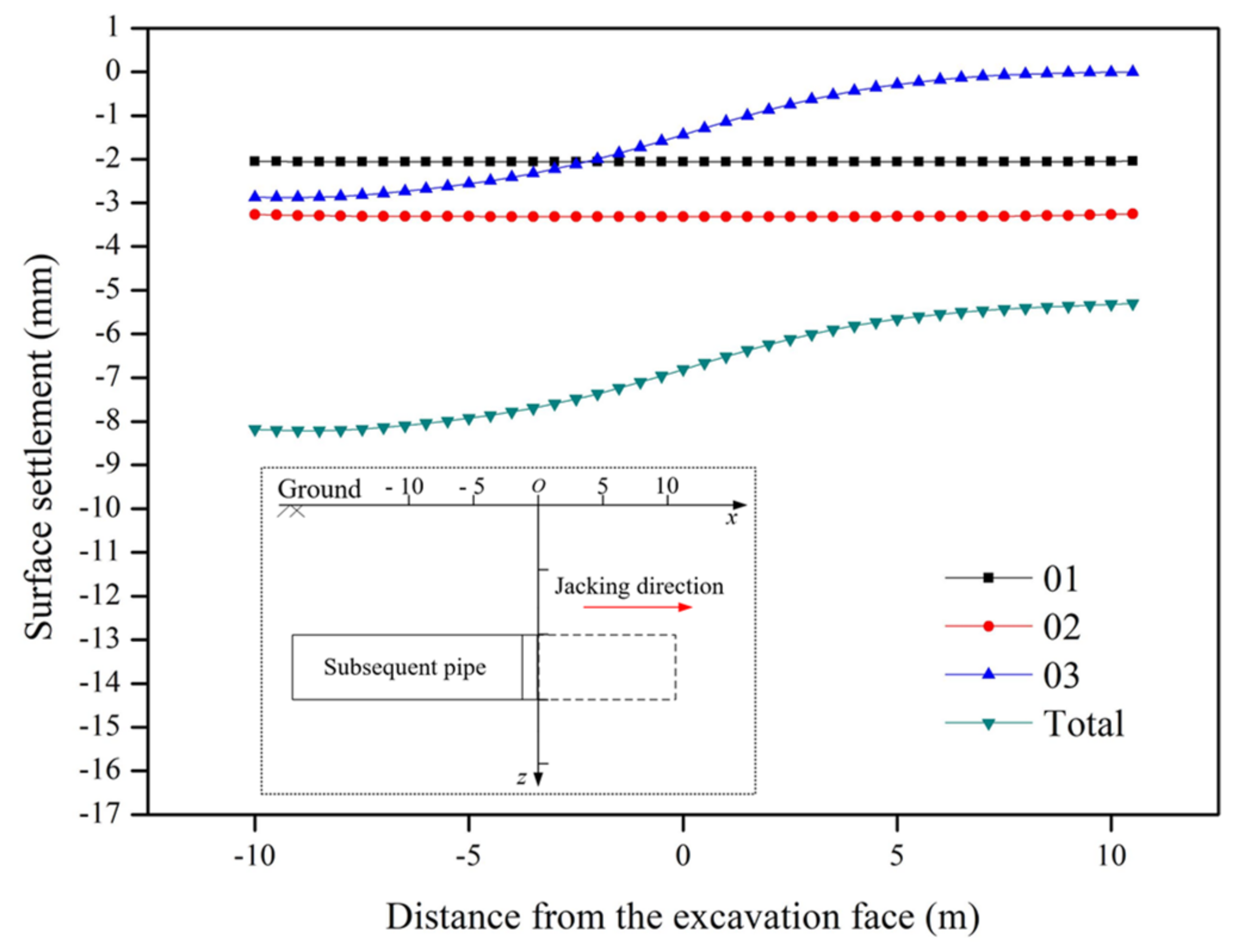
The influence range of the longitudinal settlement curve was about 8 m (four times the pipe jacking width). In the range of 5 m before and after excavation face, the settlement changed dramatically, while pipe jacking construction could cause great disturbance to the soil within this range. The maximum settlement value of the total transverse surface settlement curve tended to be located between previous constructed pipes. The influence range of the transverse surface settlement was about five times the pipe width.
(3)
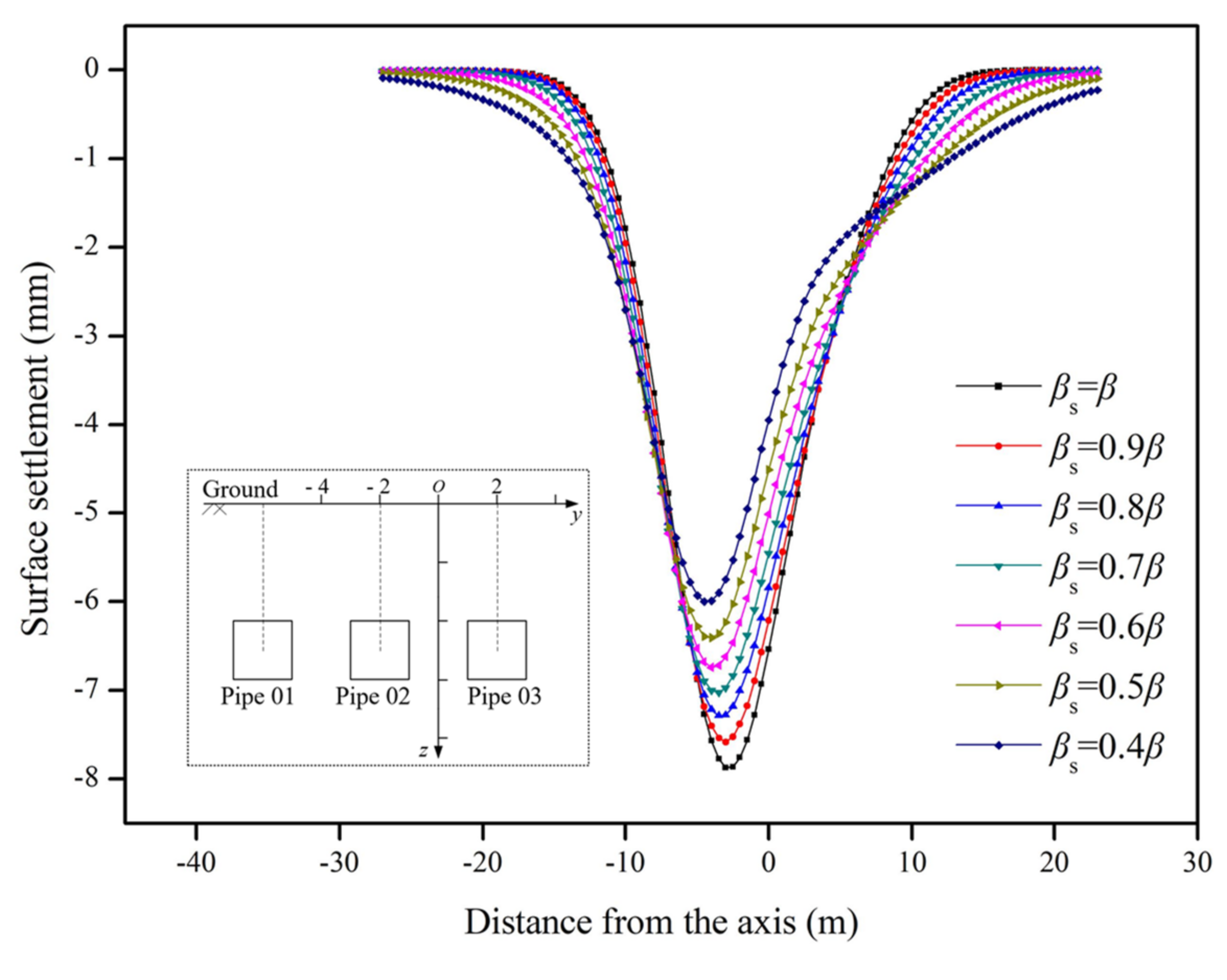
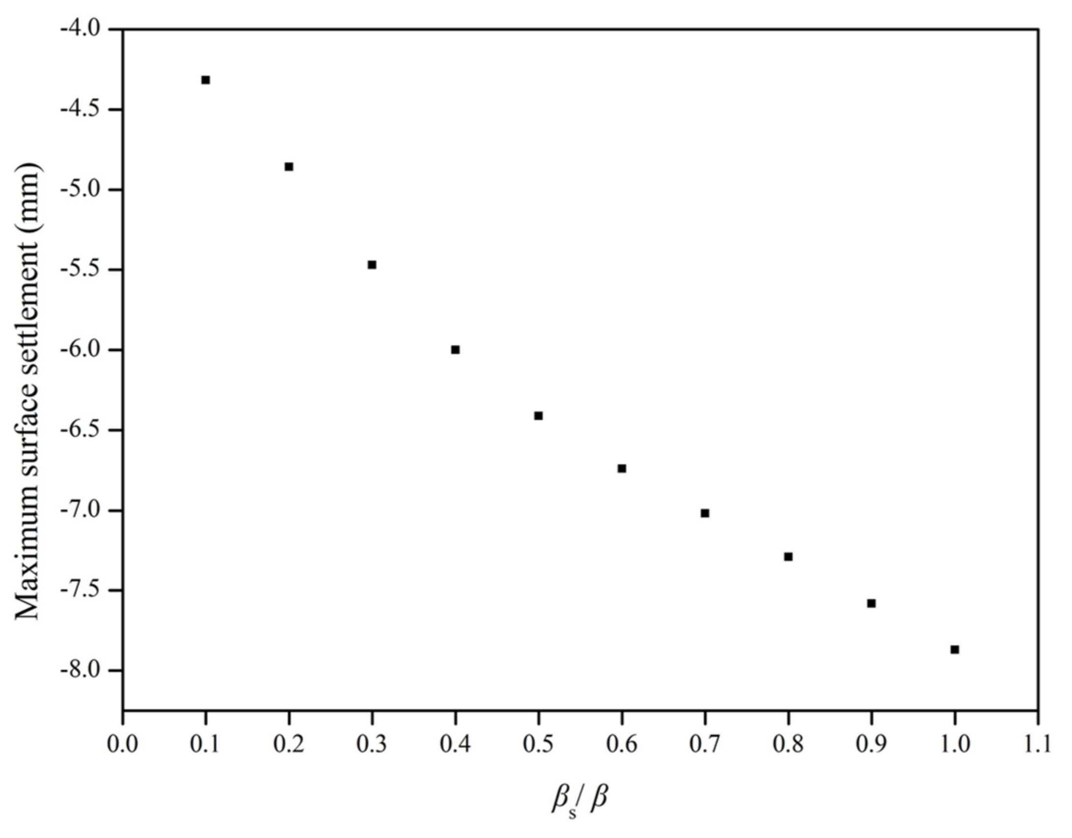
Compared with the pre-construction pipe, the post-construction pipe of the parallel pipe jacking had a larger influence range in the transverse direction, and the surface settlement trough was wide and shallow. With the decrease in the stratum influence angle of the post-construction pipe jacking, the position of the maximum settlement value moved to the pre-construction pipe jacking area, and the settlement value decreased gradually.
(4)
The convergence value has a great influence on the surface settlement curve. By controlling the soil loss during construction, the surface settlement can be effectively controlled. Therefore, thixotropic fluids should be used to reduce the disturbance of the stratum. At the same time, compensation grouting should be used to reduce the soil loss.
In order to simplify the calculation process, several assumptions were made in the model. For example, the rectification and tilt of the jacking machine were not considered. In the actual pipe jacking construction process, the various factors affecting stratum deformation are not independent, and there will be a dynamic coupling effect on the ground deformation. These problems need to be further studied.

Author Contributions

Conceptualization, Y.W., Q.F. and X.L.; methodology, Y.W.; software, Y.W.; validation, X.L., J.W. and Q.F.; formal analysis, Y.W. and X.L.; investigation, Y.W., J.W., X.L. and Q.F.; data curation, D.Z. and Q.F.; writing—original draft preparation, Y.W.; writing—review and editing, X.L., J.W. and Q.F.; visualization, Y.W.; supervision, D.Z.; project administration, D.Z.; funding acquisition, D.Z. and X.L. All authors have read and agreed to the published version of the manuscript.

Funding

This research was funded by the National Natural Science Foundation of China, grant numbers 51738002 and 52108363.

Institutional Review Board Statement

Not available.

Informed Consent Statement

Not available.

Data Availability Statement

Not available.

Conflicts of Interest

The authors declare no conflict of interest. The funders had no role in the design of the study; in the collection, analyses, or interpretation of data; in the writing of the manuscript, or in the decision to publish the results.

Abbreviations

EsCompression modulus of the soil
GShear modulus of the soil
μPoisson’s ratio
ηDistance between the excavation unit and the surface
βMain influence angle of the upper stratum
βsMain influence angle of the upper stratum around subsequent pipe
p1Additional horizontal thrust of the excavation face
p2uFriction between the top surface of the pipe jacking machine and the soil
p2dFriction between the bottom surface of the pipe jacking machine and the soil
p2lFriction between the left side of the pipe jacking machine and the soil
p2rFriction between the right side of the pipe jacking machine and the soil
p3uFriction between the top surface of the pipe and the soil
p3dFriction between the bottom surface of the pipe and the soil
p3lFriction between the left side of the pipe and the soil
p3rFriction between the right side of the pipe and the soil
p4uAdditional grouting pressure between the top surface of the pipe and the soil
p4dAdditional grouting pressure between the bottom of the pipe and the soil
p4lAdditional grouting pressure between the left side of the pipe and the soil
p4rAdditional grouting pressure between the right side of the pipe and the soil
∆tConvergence value
κGround loss ratio
SThe area of the cross-section
KThe settlement trough width coefficient
φAngle of internal friction
wVertical displacement

References

  1. Ji, X.; Zhao, W.; Ni, P.; Barla, M.; Han, J.; Jia, P.; Chen, Y.; Zhang, C. A method to estimate the jacking force for pipe jacking in sandy soils. Tunn. Undergr. Space Technol. 2019, 90, 119–130. [Google Scholar] [CrossRef]
  2. Sterling, R.L. Developments and Research Directions in Pipe Jacking and Microtunneling. Undergr. Space 2018, 5, 1–19. [Google Scholar] [CrossRef]
  3. Yu, B.Q.; Chen, C.C. Technology of Pipe Jacking Construction; China Communications Press: Beijing, China, 1998. [Google Scholar]
  4. Xie, X.; Zhao, M.; Shahrour, I. Experimental Study of the Behavior of Rectangular Excavations Supported by a Pipe Roof. Appl. Sci. 2019, 9, 2082. [Google Scholar] [CrossRef] [Green Version]
  5. Hu, X.; Deng, S.; Ren, H. In Situ Test Study on Freezing Scheme of Freeze-Sealing Pipe Roof Applied to the Gongbei Tunnel in the Hong Kong-Zhuhai-Macau Bridge. Appl. Sci. 2016, 7, 27. [Google Scholar] [CrossRef]
  6. Lee, Y.; Kim, J.; Park, I.; Kim, K.; Lee, J. A study on the applicability of under ground structure using steel tubular roof in Korean geotechnical condition. J. Korean Tunn. Undergr. Space Technol. Assoc. 2003, 5, 401–409. [Google Scholar]
  7. Li, Y.S.; Zhang, K.N.; Huang, C.B.; Li, Z.; Deng, M.L. Numerical simulation on the ground deformation by Pipe-roof Pre-construction Method. In Proceedings of the 2011 International Conference on Consumer Electronics, Communications and Networks (CECNet), Xianning, China, 16 May 2011; pp. 3291–3294. [Google Scholar]
  8. Jia, P.J.; Zhao, W.; Chen, Y.; Li, S.G.; Han, J.Y.; Dong, J.C. A Case Study on the Application of the Steel Tube Slab Structure in Construction of a Subway Station. Appl. Sci. 2018, 8, 1437. [Google Scholar] [CrossRef] [Green Version]
  9. Li, Y.S.; Zhang, K.N.; Huang, C.B. Monitoring of lining structure of tunnels built by using pipe-roof pre-construction method. Chin. J. Geotech. Eng. 2012, 34, 1541–1547. [Google Scholar]
  10. Yang, X.; Li, Y. Research of surface settlement for a single arch long-span subway station using the Pipe-roof Pre-construction Method. Tunn. Undergr. Space Technol. 2018, 72, 210–217. [Google Scholar] [CrossRef]
  11. Musso, G. Jacked pipe provides roof for underground construction in busy urban area. Civ. Eng. 1979, 49, 79–82. [Google Scholar]
  12. Park, I.; Kwak, C.; Kim, S.; Kim, J.; Han, S. Verification and general behaviour of Tubular Roof & Trench method (TR&T) by numerical analysis in Korea. Tunn. Undergr. Space Technol. 2006, 21, 394. [Google Scholar]
  13. Kwak, C.; Park, I.; Kim, S.; Kim, J. Seismic behavior of tubular roof & trench method (TR &T) by numerical analysis. In Proceedings of the Underground Space—The 4th Dimension of Metropolises, Prague, Czech Republic, 5–10 May 2007; pp. 513–518. [Google Scholar]
  14. Yang, X.; Zhang, K.N.; Li, Z.; Deng, M.L. Optimal design of distance between Jacking Pipes of New Pre-Construction Method in metro station. China Railw. Sci. 2011, 32, 6. [Google Scholar]
  15. Li, Y.; Zhang, K.; Huang, C.; Zhong, L.; Deng, M. Analysis of the ground deformation to large cross-section tunnel by Pipe-roof Pre-construction Method. In Proceedings of the Second International Conference on Mechanic Automation & Control Engineering, Inner Mongolia, China, 15–17 July 2011. [Google Scholar]
  16. Yang, S.; Wang, M.; Du, J.; Guo, Y.; Geng, Y.; Li, T. Research of jacking force of densely arranged pipe jacks process in pipe-roof pre-construction method. Tunn. Undergr. Space Technol. 2020, 97, 103277. [Google Scholar] [CrossRef]
  17. Jia, P.; Zhao, W.; Khoshghalb, A.; Ni, P.; Li, S. A new model to predict ground surface settlement induced by jacked pipes with flanges. Tunn. Undergr. Space Technol. 2020, 98, 103330. [Google Scholar] [CrossRef]
  18. Peck, R.B. Deep excavations and tunnelling in soft ground. In Proceedings of the 7th International Conference on Soil Mechanics and Foundation Engineering, Mexico City, Mexico, 25–29 August 1969; pp. 225–290. [Google Scholar]
  19. Ocak, I. A new approach for estimating the transverse surface settlement curve for twin tunnels in shallow and soft soils. Environ. Earth Sci. 2014, 72, 2357–2367. [Google Scholar] [CrossRef]
  20. Franza, A.; Marshall, A.M. Empirical and semi-analytical methods for evaluating tunnelling-induced ground movements in sands. Tunn. Undergr. Space Technol. 2019, 88, 47–62. [Google Scholar] [CrossRef]
  21. Zhang, Z.G.; Zhang, M.X.; Jiang, Y.J.; Bai, Q.M.; Zhao, Q.H. Analytical prediction for ground movements and liner internal forces induced by shallow tunnels considering non-uniform convergence pattern and ground-liner interaction mechanism. Soils Found. 2017, 57, 211–226. [Google Scholar] [CrossRef]
  22. Fang, Q.; Wang, G.; Yu, F.C.; Du, J.M. Analytical algorithm for longitudinal deformation profile of a deep tunnel. J. Rock Mech. Geotech. Eng. 2021, 13, 845–854. [Google Scholar] [CrossRef]
  23. Tao, L.J.; Zhang, Y.; Zhao, X.; Bian, J. Group Effect of Pipe Jacking in Silty Sand. J. Geotech. Geoenviron. Eng. 2021, 147, 05021012. [Google Scholar] [CrossRef]
  24. Hisatake, M.; Ohno, S. Effects of pipe roof supports and the excavation method on the displacements above a tunnel face. Tunn. Undergr. Space Technol. 2008, 23, 120–127. [Google Scholar] [CrossRef]
  25. Zeng, B.; Huang, D. Soil deformation induced by Double-O-Tube shield tunneling with rolling based on stochastic medium theory. Tunn. Undergr. Space Technol. 2016, 60, 165–177. [Google Scholar] [CrossRef]
  26. Fang, H.; Zhang, D.; Fang, Q.; Wen, M. A generalized complex variable method for multiple tunnels at great depth considering the interaction between linings and surrounding rock. Comput. Geotech. 2021, 129, 103891. [Google Scholar] [CrossRef]
  27. Fang, H.; Zhang, D.; Fang, Q. A semi-analytical method for frictional contact analysis between rock mass and concrete linings. Appl. Math. Model. 2022, 105, 17–28. [Google Scholar] [CrossRef]
  28. Verruijt, A. Complex variable solution for a deforming circular tunnel in an elastic half plane. Géotechnique 1997, 21, 77–89. [Google Scholar] [CrossRef]
  29. Yang, G.B.; Zhang, C.P.; Min, B.; Chen, W. Complex variable solution for tunneling-induced ground deformation considering the gravity effect and a cavern in the strata. Comput. Geotech. 2021, 135, 104154. [Google Scholar] [CrossRef]
  30. Mindlin, R.D. Force at a Point in the Interior of a Semi-Infinite Solid. J. Appl. Phys. 1936, 7, 195–202. [Google Scholar] [CrossRef]
  31. Niu, Z.; Cheng, Y.; Zhang, Y.; Song, Z.; Li, H. A New Method for Predicting Ground Settlement Induced by Pipe Jacking Construction. Math. Prob. Eng. 2020, 2020, 1–11. [Google Scholar] [CrossRef]
  32. Ren, D.J.; Xu, Y.S.; Shen, J.; Zhou, A.; Arul, A. Prediction of Ground Deformation during Pipe-Jacking Considering Multiple Factors. Appl. Sci. 2018, 8, 1051. [Google Scholar] [CrossRef] [Green Version]
  33. Litwiniszyn, J. The theories and model research of movements of ground. In Proceedings of the European Congress Ground Movement, Leeds, UK, 9–12 April 1957; pp. 203–209. [Google Scholar]
  34. Liu, B.C.; Zhang, J.S. Stochastic method for ground subsidence due to near surface excavation. Chin. J. Rock Mech. Eng. 1995, 14, 289–296. [Google Scholar]
  35. Yang, X.L.; Wang, J.M. Ground movement prediction for tunnels using simplified procedure. Tunn. Undergr. Space Technol. 2011, 26, 462–471. [Google Scholar] [CrossRef]
  36. Milligan, G.; Norris, P. Pipe-soil interaction during pipe jacking. Proc. Ins. Civ. Eng. Geotch. Eng. 1999, 137, 27–44. [Google Scholar] [CrossRef]
  37. Wen, K.; Shimada, H.; Zeng, W.; Sasaoka, T.; Qian, D. Frictional analysis of pipe-slurry-soil interaction and jacking force prediction of rectangular pipe jacking. Eur. J. Environ. Civ. Eng. 2018, 24, 1–19. [Google Scholar] [CrossRef]
  38. Han, X.; Li, N. Comparative analysis of strata prediction models for ground movement induced by tunnel construction. Chin. J. Rock Mech. Eng. 2007, 26, 594–600. [Google Scholar]
  39. Han, X.; Li, N. Study on subsurface ground movement caused by urban tunneling. Rock Soil Mech. 2016, 28, 609–613. [Google Scholar]
  40. Wei, G.; Zhou, Y.C. A simplified method for predicting ground settlement caused by adjacent parallel twin shield tunnel construction based on stochastic medium theory. Rock Soil Mech. 2016, 37, 113–119. [Google Scholar]
  41. Peng, G. Analysis of Surface Settlement Induced by Close Parallel Dual-tunnel Construction of Large Section Rectangular Jacking Pipe. J. Constr. Technol. 2017, 46, 70–73. [Google Scholar]
Figure 1. Schematic of pipe roof structural method: (a) pipe jacking; (b) cutting and welding of pipes; (c) pouring of concrete; (d) large-scale excavation.
Applsci 12 03298 g001
Figure 2. Schematic of stochastic medium theory.
Applsci 12 03298 g002
Figure 3. Schematic of calculation model.
Applsci 12 03298 g003
Figure 4. Areas of integration of additional horizontal thrust.
Applsci 12 03298 g004
Figure 5. Areas of integration of jacking machine friction.
Applsci 12 03298 g005
Figure 6. Areas of integration of subsequent pipe friction.
Applsci 12 03298 g006
Figure 7. Areas of integration of additional grouting pressure.
Applsci 12 03298 g007
Figure 8. Mode of soil convergence: (a) uniform convergence; (b) nonuniform convergence.
Applsci 12 03298 g008
Figure 9. Numerical simulation model of pipe jacking.
Applsci 12 03298 g009
Figure 10. Curves of transverse ground surface settlement.
Applsci 12 03298 g010
Figure 11. Curves of longitudinal ground surface settlement.
Applsci 12 03298 g011
Figure 12. Curves of transverse ground surface settlement.
Applsci 12 03298 g012
Figure 13. Curves of transverse ground surface settlement.
Applsci 12 03298 g013
Figure 14. Curves of longitudinal ground surface settlement.
Applsci 12 03298 g014
Figure 15. Curves of transverse surface settlement.
Applsci 12 03298 g015
Figure 16. Variation of maximum settlements.
Applsci 12 03298 g016
Figure 17. Curves of transverse surface settlement.
Applsci 12 03298 g017
Figure 18. Variation of maximum settlements.
Applsci 12 03298 g018
Publisher’s Note: MDPI stays neutral with regard to jurisdictional claims in published maps and institutional affiliations.

