1. Introduction
In recent years, the microwave signal generation method using microwave photonic technology has become a research hotspot. Photonics-assisted methods are considered as a promising replacement for electronic technology, with the advantages of having a wide bandwidth, low loss, and immunity to electromagnetic interference [
1,
2,
3,
4,
5]. Various photonic arbitrary waveform generation schemes have been proposed in recent years. Among all those methods, the external optical modulation method is an efficient and promising solution that generates microwave waveforms with a full duty cycle [
6,
7,
8,
9]. Typically, the external optical modulation method is based on the external modulation of a continuous wave (CW) light using electro-optical modulators. The basic principle of this method is to manipulate the modulated optical sidebands such that the generated harmonics correspond to the Fourier series expansion components of the desired pulse train in the frequency domain. A method of generating multi-functional signals, including short pulses, trapezoidal, triangular, and sawtooth waves, and double pulses based on a dual-driven Mach-Zehnder modulator (DDMZM) was proposed in [
10], but additional dispersive fiber was required to filter the signal sideband. W. Liu proposed a method to generate microwave waveform by using a sinusoidal signal to modulate the sideband generated by the polarization modulator (PolM) in Sagnac loop, but the system was vulnerable to nonlinear effects [
11]. A photonic approach to generate triangular and rectangular waveforms based on a dual-parallel Mach-Zehnder modulator (DPMZM) and a tunable bandpass filter (TBPF) was proposed in [
12]; however, the TBPF increased the complexity of the system. Recently, a polarization-division multiplexing Mach-Zehnder modulator (PDM-MZM) and a balanced photodetector (BPD) to generate a microwave waveform was proposed in [
13]. Ref. [
14] proposed a novel photonic approach for generating an arbitrary waveform, which was based on the property of real-time Fourier transform in the temporal Talbot effect. In addition, the optoelectronic oscillator (OEO) is a well-known high-frequency oscillator for generating low-phase microwave and millimeter-wave signals without employing any external microwave sources, which typically consists of many components such as a laser diode, optical fiber, modulator, photodiode, and a feedback loop complete with an electrical bandpass filter and electrical amplifier. A possible implementation of a centralized micro- and millimeter-wave signal generated by OEO distribution as a local oscillator for a 5G radio access network (RAN) was demonstrated in [
15]. In paper [
16], a dual-polarization modulator was used to realize a polarization multiplexed optoelectronic oscillator, by properly setting the amplitudes of the two signals that had been generated by the proposed OEO, a triangular pulse train could be generated. In [
17], a self-starting OEO was built to offer stable microwave signals to generate microwave waveforms, but the scheme needed a filter both in the optical and the electrical domain. Most of the microwave waveform generators based on OEO require stabilization for short-term, long-term, and multimode operation [
15].
In this paper, we propose and experimentally demonstrate a simple photonic method for the generation of full-duty-cycle sawtooth, square, and triangular waveforms by Dpol-DDMZM. Hence, the filtering or dispersive optical devices which have been involved in previous approaches [
10,
11,
12,
15,
17] obviate the need. This scheme only requires a sinusoidal radio frequency (RF) source, a laser diode (LD), a 3 dB divider, a phase shifter (PS), a dual-polarization dual-drive Mach-Zehnder modulator (Dpol-DDMZM), and a photodetector (PD). According to the Fourier series of the desired waveform, the working point and modulation depth of Dpol-DDMZM are properly set to make the first-order, second-order, and third-order harmonic signals of the photocurrent from the spectrum of the desired pulse sequence. A proof-of-concept experiment was implemented to verify the concept, and the three microwave waveforms with repetition rates of 8GHz were successfully generated. The RMSE between the generated and the theoretical were all less than 2%. The scheme only used a commercial off-the-shelf modulator to generate more kinds of waveforms, which features a simple structure and better universality.
2. Principle and Simulation
The configuration of the proposed waveform generation scheme is shown in
Figure 1. In the proposed scheme, an optical carrier generated from an LD is coupled into a pol-DDMZM with two-quadrature polarizer DDMZMs. Two sub-MZMs (DDMZM1 and DDMZM2) are embedded in each arm of the main modulator. Each of the DDMZMs has two RF input ports and two DC input biases, respectively. The sinusoidal RF signal is split into two channels by the 3 dB divider, with one output port connected to DDMZM1 and the other output port connected to DDMZM2 via the PS. The optical signal is modulated by the RF signal via the Dpol-DDMZM to generate optical sidebands.
Assume that the input optical carrier in LD is expressed as
,
VRF and
WRF are the amplitude and frequency of the RF signal, and
VDC1 and
VDC2 denote the two bias voltages applied to the upper and lower arms of the DDMZM, respectively. From [
18], the optical field at the output of DDMZM can be expressed as follows:
where
and
are phase shifts determined by the bias voltages,
represents the phase difference caused by the two bias voltages, and
is the modulation index of the DDMZM;
θ is the phase difference of the RF signals applied to the two arms, where
, and the DDMZM works in a complementary push–pull state. In this scheme, the optical field at the output of two sub-MZMs (DDMZM1 and DDMZM2) can be respectively expressed as follows:
where
represents the phase difference of the DDMZM1 caused by the two bias voltages,
represents the phase difference of the DDMZM2 caused by the two bias voltages,
represents the phase difference of the RF signal loaded by the upper DDMZM1 and the lower DDMZM2 of the Dpol-DDMZM.
The optical field at the output of Dpol-DDMZM can be expressed as follows:
The Fourier expansion of the sawtooth, triangular, and square waveforms can be approximately expressed as follows:
- A.
Sawtooth waveform
If we set
in DDMZM1, it is operated at the quadrature transmission point (QATP). For DDMZM2, it is set at the maximum transmission point (MATP), where
. When the condition above is inserted in Equation (4), the optical signal output by the Dpol-DDMZM can be written as follows:
Because two DDMZMs work in quadrature polarization directions, the optical signal will not interfere with each other. When this optical signal is sent to a PD for intensity detection, the output current of the PD is given by the following equation:
where
is the responsivity of PD,
represents
,
denotes the n-th order of the first kind of the Bessel function. By comparing Equation (7) with Equation (5), we can see that if the following conditions can be satisfied, then a sawtooth waveform can be generated:
The phase difference,
, can be adjusted by varying the PS. In addition, the ratio between the Bessel functions can be adjusted by changing the modulation depth of each DDMZM. The relationship of the Bessel functions and the modulation index are plotted in
Figure 2. As we can see, when
, the ratio
r1/2 = 2 is satisfied. Moreover, if we set the modulation index of DDMZM2 to
, then
r1/3 = 3 is satisfied.
Comparing Equation (9) with Equation (5), the relationship between frequency and phase satisfies the requirement for sawtooth waveform generation, and the desired full-duty sawtooth pulse train is successfully obtained.
- B.
Triangular and Square waveform
Similarly, if both DDMZMs are operated at QATP, that is,
, the optical signal output by the Dpol-DDMZM can be written as follows:
The current output after the PD can be expressed as the following equation:
We adjust the modulation depth of two DDMZMs to satisfy the following Bessel function:
. According to
Figure 2, the modulation index is
. Additionally, by setting
, Equation (11) can be simplified as follows:
where
represents the DC current. Comparing Equation (12) with Equation (5), the relationship between frequency and phase satisfies the requirement for triangular waveform generation, and the desired full-duty triangular pulse train is successfully obtained.
Again, we adjust the modulation depth of two DDMZMs to satisfy the following Bessel function:
. As shown in
Figure 2, the modulation index is set as
. The optical signal at the output of PD is as follows:
Then, simply let
, and Equation (13) can be simplified as follows:
Comparing Equation (14) with Equation (5), the relationship between frequency and phase satisfies the requirement for square waveform generation, and the desired full-duty square pulse train is successfully obtained.
According to the theoretical analysis, a simulation system is built to verify the method. The parameter settings are shown in
Table 1.
According to the discussion above, we set the modulation depth of DDMZM1 at 1.73, and the modulation depth of DDMZM2 at 2.30; meanwhile, the RF phase difference between the two DDMZMs is set at 45°.
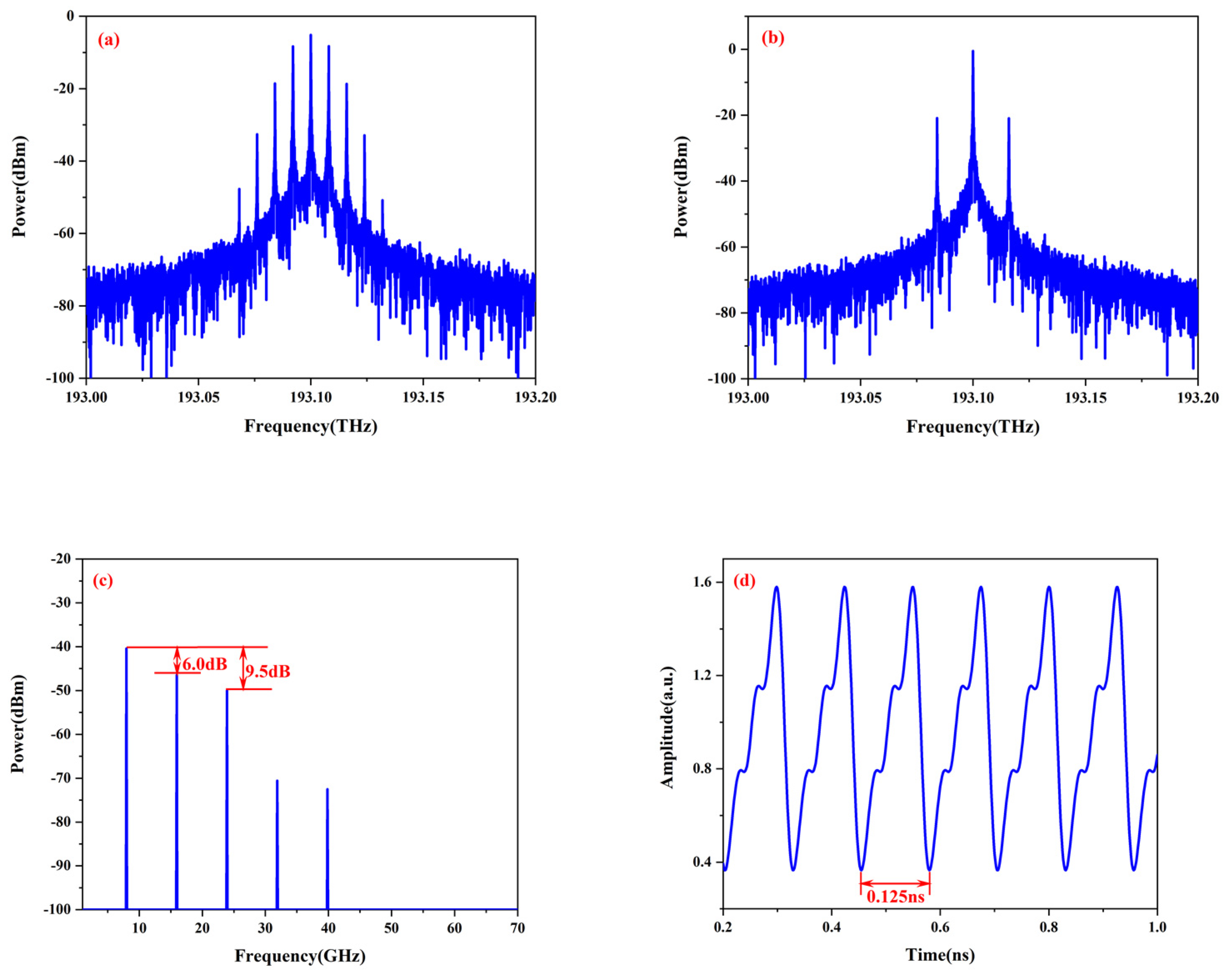
The output optical spectrum in DDMZM1 is shown in
Figure 3a, which constitutes the odd order component of the sawtooth wave. In addition,
Figure 3b shows the optical spectrum at the output of DDMZM2, which constitutes the even order component of the sawtooth wave.
Figure 3c shows the output waveform spectrum after PD. In this spectrum, the even harmonic power is 6.0 dB lower than the fundamental frequency power, and the third harmonic power is 9.5 dB lower than the fundamental frequency power, which is consistent with the spectrum characteristics of a theoretical sawtooth waveform.
Figure 3d is the output signal waveform in the time domain, which is consistent with the waveform of the sawtooth signal with a full duty cycle and a repetition frequency of 8 GHz (0.125 ns).
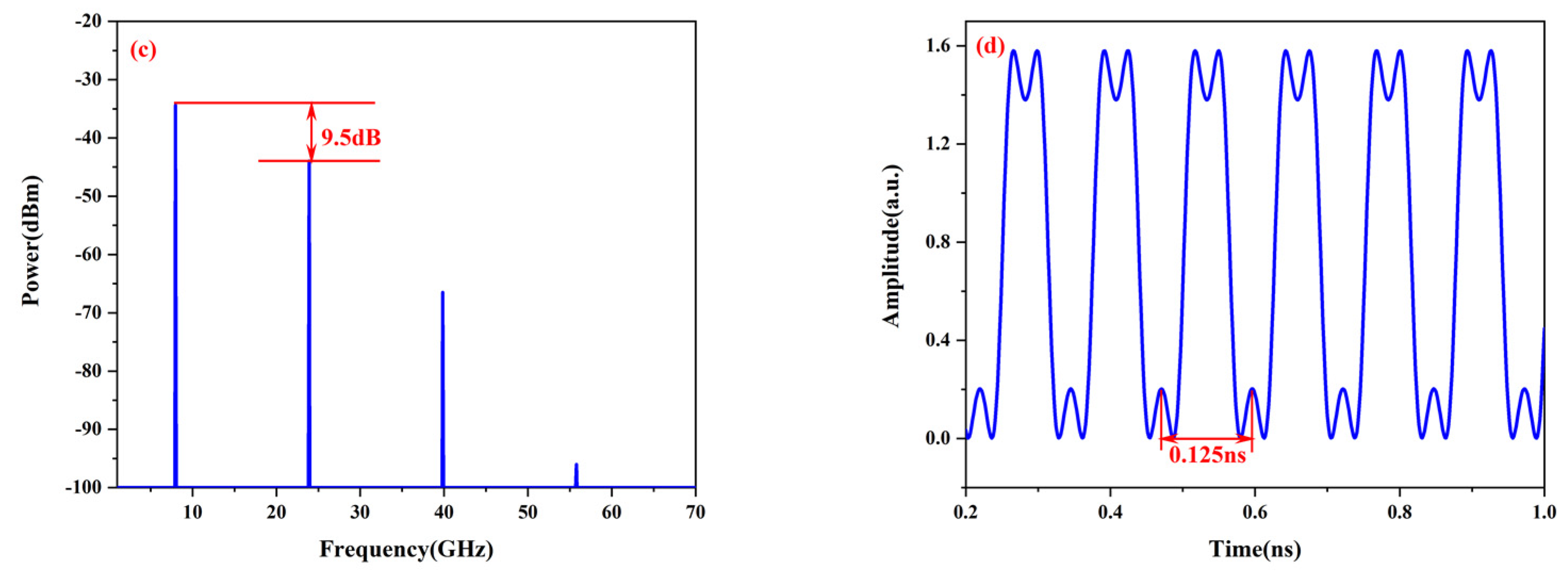
The simulation results on triangular and square waveforms can be seen in
Figure 4.
Figure 4a shows the output of the triangular waveform spectrum after PD. As we can see, the third harmonic power is 19.1 dB lower than the fundamental frequency power, which is consistent with the spectrum characteristics of the theoretical triangular waveform.
Figure 4b is the output signal waveform in the time domain, which is consistent with the waveform of the triangular signal with a full duty cycle and a repetition frequency of 8 GHz (0.125 ns).
Similarly,
Figure 4c shows the generated square waveform. The third harmonic power is 9.5 dB lower than the fundamental frequency power, which is consistent with the theoretical calculation.
Figure 4d is the output signal waveform in the time domain.
3. Experiment and Results
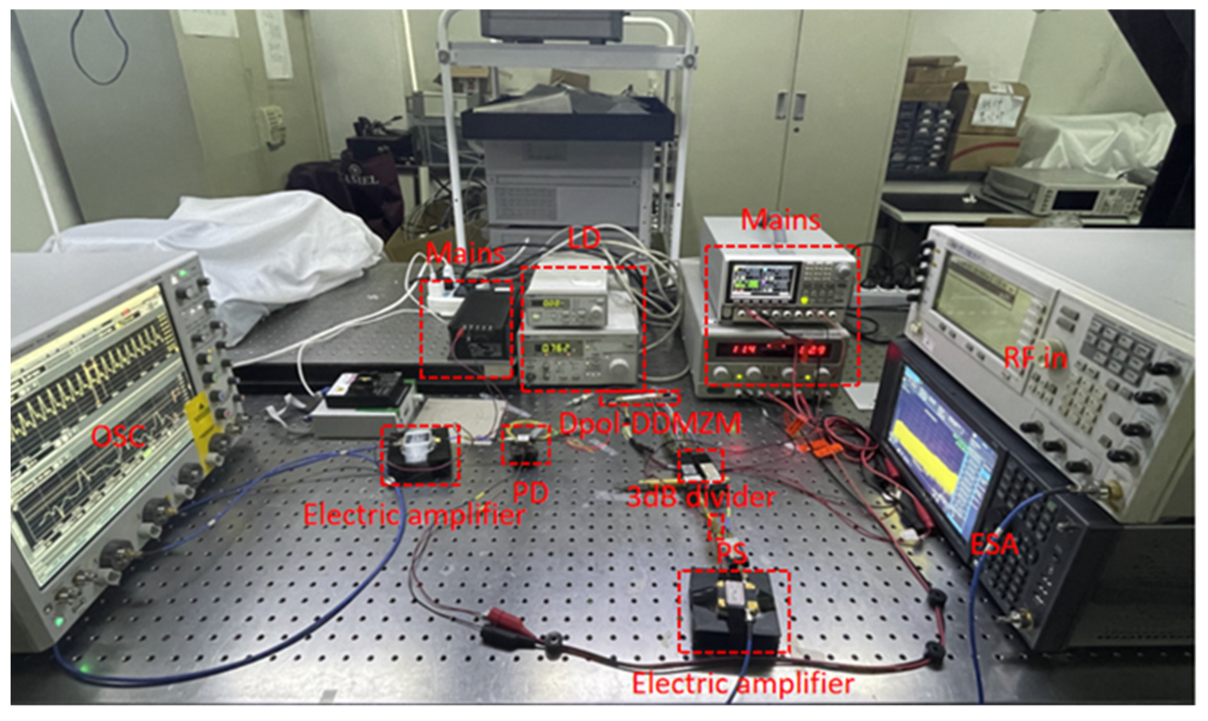
In order to verify the effectiveness of the proposed scheme, a proof-of-concept experiment is conducted according to the principle framework in
Figure 1. As shown in
Figure 5, the optical signal from the laser (DFB, EMCORE 1772), with the wavelength of the C-band and a power of 10 dBm, was sent to the Dpol-DDMZM (FTM7980EDA, 21.5 GHz). The modulator had a half-wave voltage of 3.5 V. Moreover, it was biased at the appropriate working point. An 8 GHz RF signal generated from the single frequency source (Agilent E4438C) was first boosted by an electrical amplifier with a gain of 30 dB and was then inserted into a 3 dB divider. A PS was used to adjust the power and the phase difference of the RF between the two DDMZMs. The modulated optical signal at the output of the Dpol-DDMZM was then sent to the PD (Finisar, 50 GHz) for intensity detection. The responsivity of the PD was about 0.6 A/W, and the 3 dB bandwidth was 50 GHz. An electrical amplifier with a gain of 30 dB was employed after PD to boost the generated pulse train signal. In the end, the electric signal was divided by a 3 dB divider. One part was sent to the electrical spectrum analyzer (ESA, Keysight, N9030B) and the other to the oscilloscope (OSC, Keysight, DSOZ592A). The parameter setting of the experiment device was adjusted according to the simulation.
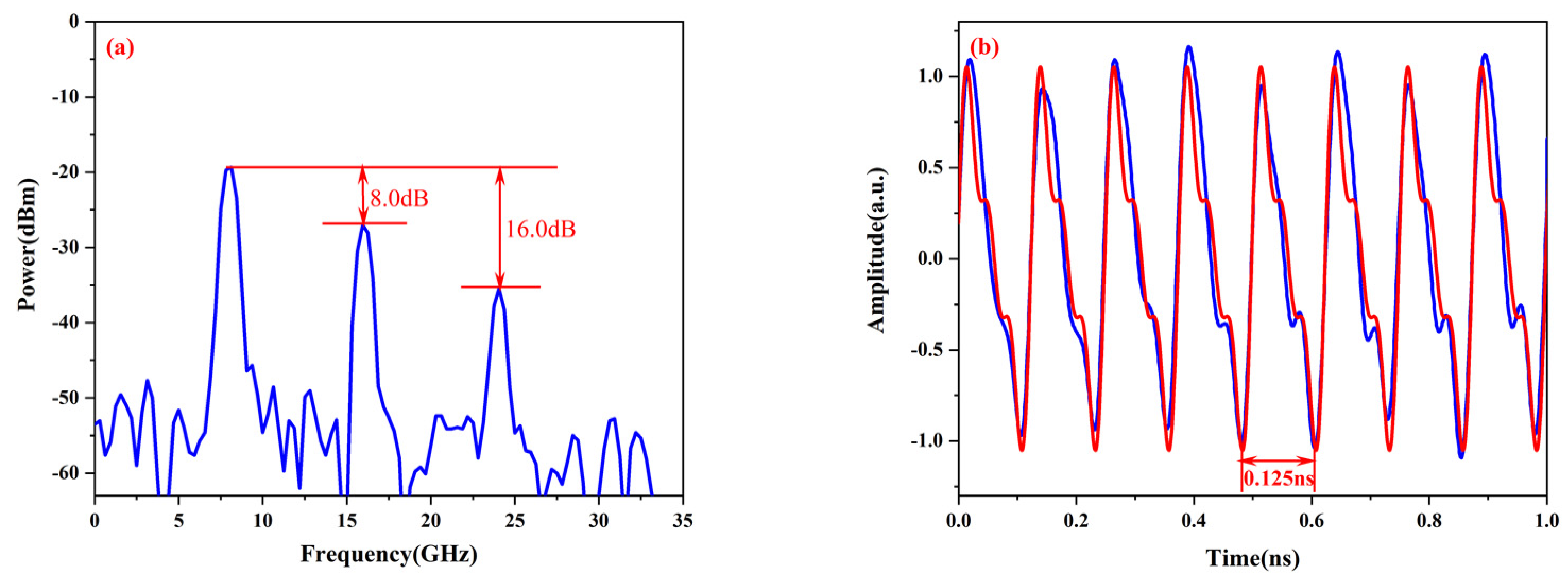
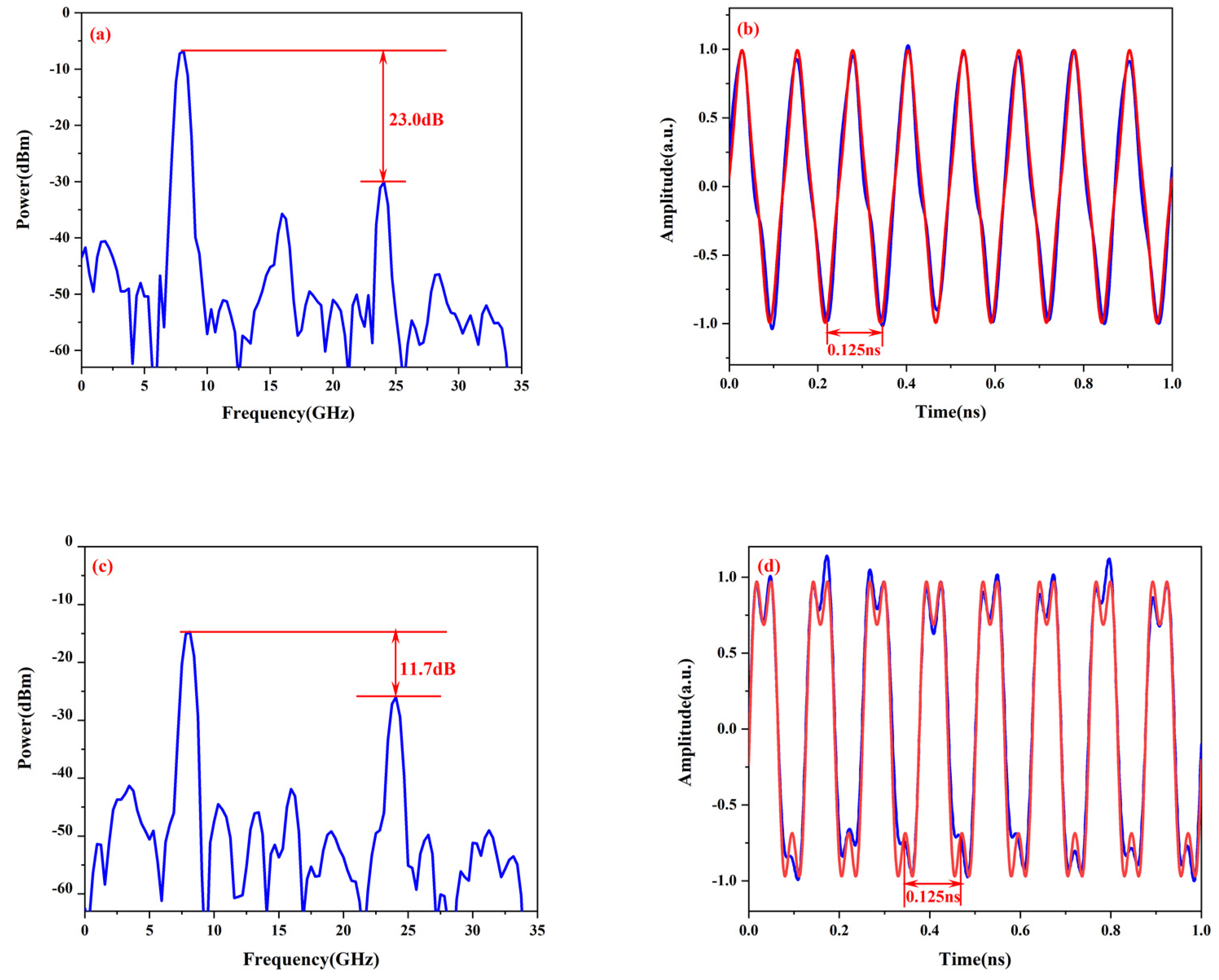
Figure 6 shows the electrical power spectrums and generated waveforms of the sawtooth; in
Figure 6a, the even harmonic power is 8.0 dB lower than the fundamental frequency power, and the third harmonic power is 16.0 dB lower than the fundamental frequency power, both of which are roughly similar to the values in the simulation (6.0 dB and 9.5 dB).
Figure 6b is the output signal waveform of the PD in the time domain, which is consistent with the ideal waveform of the sawtooth signal. The RSME between the generated and ideal waveform is less than 0.190.
Figure 7 shows the experiment results of the electrical power spectra and the waveforms, respectively. As marked in
Figure 7, the ratio between the third harmonic power and the fundamental frequency power is also very close to the value obtained in the simulation. The RSME between the generated and ideal waveform is less than 0.168 for the triangular waveform and 0.135 for the square waveform. In the experiments, the waveform generated in the time domain is not perfect, and the frequency spectrum in the electrical domain is deviated from the ideal frequency spectrum. The main reason is that we used a small signal source and electric amplifier to replace the high-power signal source, which introduced unwanted harmonics.


 ,
, 


