Article

Design of Fiber-Composite/Metal–Hybrid Structures Made by Multi-Stage Coreless Filament Winding

1
Institute for Textile and Fiber Technologies, University of Stuttgart, Pfaffenwaldring 9, 70569 Stuttgart, Germany
2
Institute of Industrial Manufacturing and Management, University of Stuttgart, Allmandring 35, 70569 Stuttgart, Germany
3
Fraunhofer Institute for Manufacturing Engineering and Automation, Nobelstraße 12, 70569 Stuttgart, Germany
4
Institute for Virtual Product Development, Aalen University of Applied Sciences, Beethovenstraße 1, 73430 Aalen, Germany
5
German Institutes of Textile and Fiber Research Denkendorf, Körschtalstraße 26, 73770 Denkendorf, Germany
*
Authors to whom correspondence should be addressed.
Appl. Sci. 2022, 12(5), 2296; https://doi.org/10.3390/app12052296
Submission received: 5 February 2022 / Revised: 19 February 2022 / Accepted: 20 February 2022 / Published: 22 February 2022
(This article belongs to the Topic Composites in Aerospace and Mechanical Engineering)

Abstract

:

Featured Application

The methods presented in this study assist in fabricating load-bearing structures with high mass-specific mechanical performance at various scales. Possible applications include primary and secondary structures in engineering, architecture, automotive, or aerospace industries.

Abstract

Additive manufacturing processes, such as coreless filament winding with fiber composites or laser powder bed fusion with metals, can produce lightweight structures while exhibiting process-specific characteristics. Those features must be accounted for to successfully combine multiple processes and materials. This hybrid approach can merge the different benefits to realize mass savings in load-bearing structures with high mass-specific stiffnesses, strict geometrical tolerances, and machinability. In this study, a digital tool for coreless filament winding was developed to support all project phases by natively capturing the process-specific characteristics. As a demonstration, an aluminum base plate was stiffened by a coreless wound fiber-composite structure, which was attached by additively manufactured metallic winding pins. The geometrical deviations and surface roughness of the pins were investigated to describe the interface. The concept of multi-stage winding was introduced to reduce fiber–fiber interaction. The demonstration example exhibited an increase in mass-specific component stiffness by a factor of 2.5 with only 1/5 of the mass of a state-of-the-art reference. The hybrid design approach holds great potential to increase performance if process-specific features, interfaces, material interaction, and processes interdependencies are aligned during the digitized design phase.

1. Introduction

Beginning in the 1960s, the adoption of carbon fiber reinforced plastics (CFRPs) in structural engineering was primarily motivated by their superior mass-specific mechanical parameters, which can be tailored to the individual application [1]. While CFRPs incorporate a low thermal expansion [2] together with non-magnetic [3] and non-corrosive properties [4], their drawbacks include limited recyclability [5], reparability [6], and often non-destructive quality control [7], as well as a high environmental impact [8].
Coreless filament winding (CFW) is an emerging composite manufacturing process that has not yet reached its full potential for high-performing and efficient structures due to limiting software design tools. In CFW [9,10,11,12], a roving is spanned freely between point-like anchors to additively manufacture a component, such as lattices [13,14] or shells [15,16]. The constantly tensioned [17] fiber strand is usually impregnated online [18] with a thermoset resin in a bath or by an end-effector [19]. Alternatively, pre-tows [20] can be deployed. CFW is distinguished from conventional winding techniques [21,22] in that the component shape can be well described by straight lines connecting several anchor points in a specific sequence. Geometrical deviations in the fiber net can arise through fiber–fiber interaction only, whereas in hybrid forms [23,24], the fibers are also partially supported by surfaces. The benefit of CFW is decoupling the tooling from the composite structure, which enables cost-effective adaptability of components and leads to minimizing tooling costs while increasing fiber–fiber interaction, which is hard to predict and control. Recent demonstrations of CFW were directed towards building applications [25] and validated design [26], simulation [27], manufacturing [28], testing [29], approval, and monitoring [30] procedures. Where these research-orientated custom solutions are fragmented between different software tools and platforms, widely used proprietary CAD/CAM tools are intended for prismatic geometries in isotropic materials. Software directed towards composite and textile-based characteristics mostly depends on a layer-based design [31], which CFW often does not exhibit. Recently, a first step towards an integrative software tool for CFW was undertaken by the creation of a common data framework, which was validated in a case study [20,32].
One challenge of designing with CFW is to find the structurally most efficient framework structure in compliance with CFW fabrication characteristics. This is driven by two effects: minor reconfigurations of the fiber net can cause disproportional changes [33] in the mechanical behavior of the structure, and the addition of an additional node exponentially increases the number of possible configurations. The number of all configurations is given by n(n−2) depending on the number of nodes n [34]. Although this includes self-similar configurations and ones that do not involve all given nodes, the number is still so large that evaluating all reasonable combinations is currently not economical for technical applications. Another challenge in CFW is the digital capturing of fabrication deviations to feed structural simulations. Due to the geometrical complexity, fiber–resin-, and fiber–fiber interactions, current simulation tools can resolve only simpler components (Figure 1) on the roving level [35]. Larger and more complex structures are calculated based on approximative models, which rely on a correct calibration of material properties, which are generated by full-scale destructive tests [36].
During the design process, less sophisticated structural simulations are sufficient to evaluate fiber net configurations, but the rather linear design process [33] (Figure 1) is still limited by human intuition and experience. In multi-material [37] components, the various materials can take on different tasks, and material parameters can be set depending on the location.
Unlike CFW, additive manufacturing (AM), in the form of 3D printing, has evolved in the last decades, from being used in prototyping and research to industrial manufacturing. One reason for this is the presence of the complete digital process chain from design to machine control in AM. A variety of AM processes, for thermoplastic, short-/long-fiber-reinforced plastics, and metals enables the user to create complex shapes that are not possible or not economical with conventional manufacturing technologies, such as lathing, milling, and drilling. Similar to CFW, in AM, specific parameters become relevant, such as layer-interphases, supports and infills, wall thicknesses, warping, sagging, build plate adhesion, overhangs, and multi-material phenomenon. AM also decouples the component design from the manufacturing tool, which allows each component to be individual. Although CFW is restricted to having similar component topologies within the same fabrication setup, it outperforms AM in build volume and speed [19]. In this study, laser powder bed fusion (LPBF) was utilized to manufacture the anchor elements for the CFW structure. In LPBF, a moveable laser beam selectively melts metal powder layer-by-layer together under an inert atmosphere [38].
Conventional manufacturing technologies remain a valid option for manifold applications, especially when AM or CFW do not match the needed design language, are too slow in manufacturing, exhibit too high material costs, or lack other features. A combination of AM with the subsequent use of conventional technologies is possible but not advisable in CFW due to the fiber-composite character of the structures.
This study presents methods to synergistically combine CFW, AM, and conventional manufacturing methods, and to exploit the specific characteristics of each process and material system. Within an application-based case study, this design approach was showcased, together with a custom-coded CFW design and data management tool that accompanied all project phases. The selected case study object offered a direct comparison with the state of the art in mechanical engineering. The digital tool aims to improve the CFW design workflow by utilizing graph-theoretical representations to streamline manufacturing by providing a digitally verified winding plan and to facilitate object management through database capabilities. A holistic digital representation can increase the process efficiency and manageability, resulting in overall cost savings. The implementation of multi-stage winding [39] into CFW aims to reduce the deformation of the fiber net caused by fiber–fiber interactions, which simplifies digitally representing the object. Manufacturing characteristics of the used LPBF processes were investigated with relevance to the design approach and fiber-composite material. In particular, the dimensional accuracy of the winding anchors must be ensured for the multi-material interplay.

2. Materials and Methods

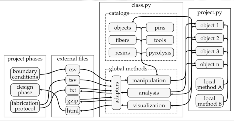
2.1. Object-Oriented Design and Management Tool

This study developed a digital CFW design tool to assist during all the project phases. CFW structures are best described by a graph-theoretical [40] approach due to their shape characteristics. In the most fundamental level of detail, anchors are represented by nodes as points with cartesian coordinates, and edges as connecting lines represent the fiber bundles (Figure 2b). The undirected graph is stored as an edge list, not as an adjacency matrix [41]. This is more efficient because only a few of all possible connections are present. Self-connections (1–1, 2–2, …) are not relevant; therefore, the diagonal of the adjacency matrix is filled with zeros. Nodes are numbered with integers and may contain data on external force inductions and the anchor orientation, both as vectors (Figure 2a). The fiber path (Figure 2c) is stored as a sequence of nodes, which is called winding syntax [42]. It is often separated into several sub-syntaxes, which start and end at the same node. It can be advantageous to define the path as a repetition of local direction statements if the syntax has a regular shape.
Building upon this fundamental digital representation (node coordinates, graph, and path), several features can be implemented independently from each other to increase the level of detail and the precision of predictions:
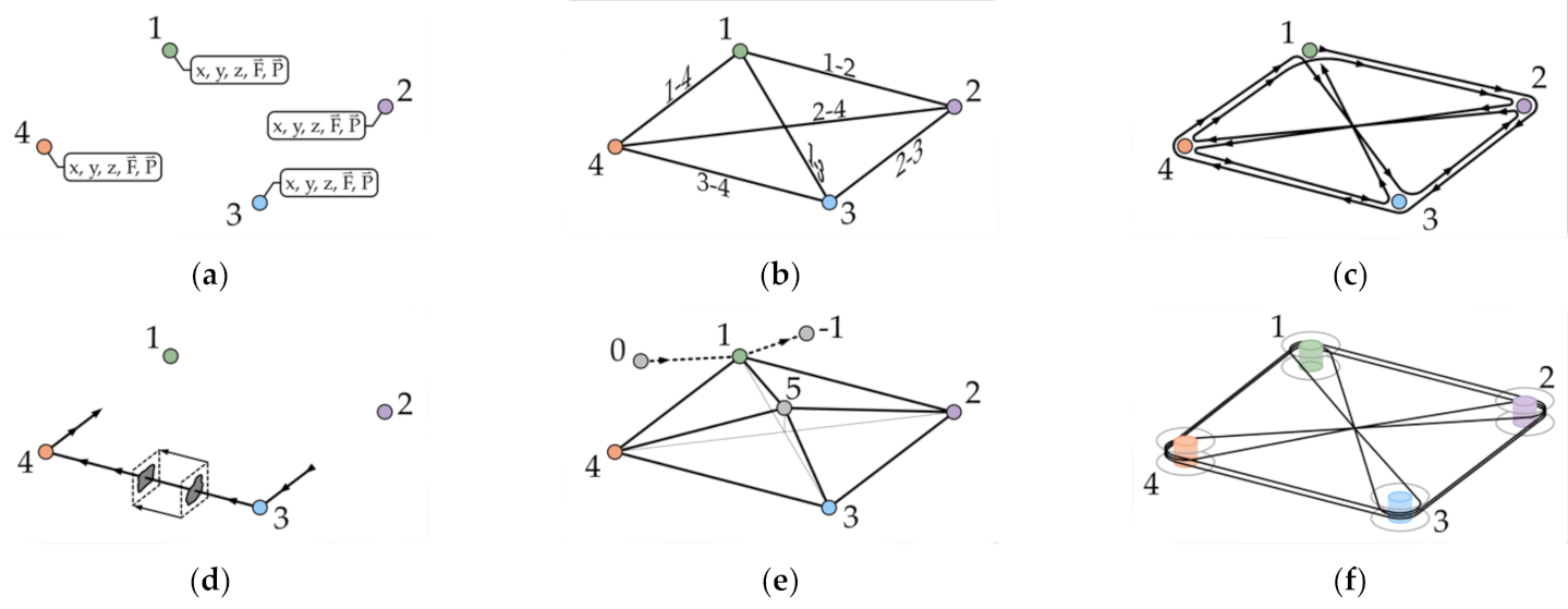
  • Additional control points can be implemented to connect two fibers at a crossing point properly, to deform the fiber net, or both (point 5, see Figure 2e). Nodes represent anchors, while control points do not. A single edge between two nodes or control points is called a segment, while the connection between two nodes is called a section and may contain several segments.
  • Two additional nodes (0 = pre_start_node, −1 = post_end_node, see Table A1) represent the protruding segments required at the beginning and end of the CFW process (Figure 2e). The model can be adjusted to match the fabricated structure by relocating existing nodes or control points and by adding new ones.
  • A (uniform) subdivision of the segments along the fiber path can be implemented to add local information along the fiber path, such as cross-sectional parameters (Figure 2d), local fiber volume ratio (FVR) deviations, or strain-field measurements by a fiber-optical sensor (FOS) system [43].
  • Around anchors, the actual circular fiber arrangement caused by the wrapping can be implemented with a polyline (Figure 2f). Depending on the hooking condition [44], the fiber path is longer than the direct connection, and the ends of the adjacent segments are radially offset. This lets the actual fiber net deviate from the graph for structures that are small in relation to their anchors.
The developed digital design tool (Figure 3) is an object-oriented Python (version 3.7.7) script to digitally represent and analyze CFW objects. It has dependencies mainly to numpy [45], pandas [46], plotly [47], and scipy [48]. The script operates on all beforementioned levels of detail and helps during all project phases, from design, over simulation, and fabrication to managing the finished components. When adding a level of detail, the fundamental representation of the object is preserved.
The tool consists of a class containing predefined functions (methods) and catalogs that permanently store object-independent parameters. One or more project files store the attributes of the winding objects and access the catalogs and methods of the class. If necessary, further custom methods can also be defined locally in the project files. Methods are used to manipulate, analyze, and visualize data. Adaptor methods provide import, export, and cache functionalities. External csv files provide data of nodes, control points, and the graph. During the design phase, dynamic visualizations and tables are output as html. The gzip format is used to cache data between calculation steps. The syntax can be exported as txt for winding preparation. After production and mechanical testing, the measurement data and syntax adjustments are read as txt files. Strain-field data from the FOS are available as tsv files.
Catalogs are defined in the class as dictionaries and contain parameter sets (Table 1) for fiber materials, resin materials, winding pins, and winding tools. The parameter sets for frequently used materials and equipment are predefined, while for new ones, the respective class methods (learn-methods, see Table A2) are used to add them. The object catalog includes all currently active objects and their attributes to allow easy data exchange and comparisons. The pyrolysis [49] catalog also comprises a list of previously conducted FVR measurements. Data sets that are imported from a catalog can be overwritten locally in the project file for any object individually.
Each winding object is stored as a collection of attributes in a centralized curated data storage, where only the basic parameters are saved. Non-fundamental parameters are calculated automatically. During the initialization of an object, all attributes are created and set to None. Subsequently, the methods are used to define the correct parameter values of the attributes step by step. Some parameters are needed in multiple variants, based on the project phase (justified assumption or direct measurement) or based on the source of data (theoretical calculation or real measurement). All variants of a parameter are stored together in its attribute. The object attributes (Figure 4, Table A1) are structured in groups, including geometrical parameters (graph), fiber material, resin material, winding syntax, hooking syntax, winding pin (anchor), production parameters, physical parameters, mechanical testing, and fiber-optical sensor data.
A variety of specialized methods (Figure 4, Table A2) are included within the CFW class definition that are static or act on the object (self) or on the class (cls). Besides basic functionalities for manipulating the object data, there are also methods that operate in a higher level of detail. Examples include creating a discretized fiber path, performing a framework analysis, obtaining physical parameters, tabulating selected attributes, or plotting them in 2D or 3D. Most of the methods are structured by a leading keyword. Add-methods create an entity within the object model and initialize its parameters. Check-methods evaluate the object parameter without changing them. Find-methods compute object parameters based on other object attributes. Learn-methods add parameters to the catalogs of the class. List-methods collect object parameters in an array-like arrangement. Plot-methods create a visual output for the user. Set-methods overwrite or define the parameters of a single object attribute.
As the graph-theoretical parameters (Figure 4, red group) are the basis of the object model, almost every method accesses these attributes. The other groups of attributes represent certain levels of detail, so the corresponding methods primarily access the respective attributes. An example of this would be the methods and parameters which belong to the fiber-optical sensors group (Figure 4, blue group). In contrast, the analysis- and visualization-methods access a variety of attributes from different groups. Especially the find-methods, which provide higher-level functions, including calls to other methods. Static- and class-methods do not access the attributes of the object. In Figure 4, the set- and learn-methods that read and store parameters in the catalogs (Table 1) are shown with their connection to the corresponding object attributes.

2.2. CFW Design Procedure

The design of a CFW structure mainly focuses on the fiber net form-finding, including the winding and hooking syntax, since it determines the structural performance together with the material parameter. The hooking syntax is a list that enumerates the hooking conditions for each winding step for each anchor [44].
Because it is not economical to compute and evaluate all permutations of the fiber net and the winding plan, the strategy followed in this study was to reduce the design space as best as possible based on an initial design approach. For this, several geometrical-, structural- and fabrication-orientated conditions can be utilized, which must be defined in accordance with the application scenario of the component and fabrication setup. The predefined methods allow the analysis of the winding object to evaluate permutations based on such criteria. Checking the wrapping angles at each node allows evaluating if there are too strong fiber diversions reducing strength (acute angle), or if there is not enough curvature causing fibers to lose contact with the anchors (flat angle). A windability test checks if all the segments along the winding path can be deposited from one or more source points without being blocked by previously placed fiber segments. This is important because CFW does not currently allow fibers to be threaded through. In addition, it is possible to check whether a graph is Eulerian, i.e., whether it has a path that starts and ends at the same node and passes all edges once [50]. This is often desirable in CFW, although multiples greater than one are also relevant. For example, it may happen that a structure must be wound not once but twice to fulfill this criterion (Figure 2). The design process follows a linear procedure with multiple iterations if necessary:
  • Definition of boundary conditions, such as build volume, mass budget, load inductions points, anchor geometry, load cases, center of gravity, and second moments of inertia;
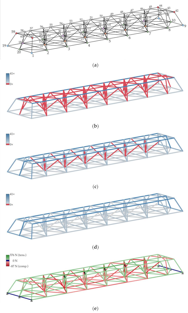
  • Topology optimization (based on voxels or frameworks) to identify the load path for all relevant load cases;
  • Translation of this initial design into a simplified graph (nodes, control points, and edges);
  • Framework analysis to estimate the material distribution for each edge;
  • Creation of the winding syntax and separation in sub syntaxes and bridges;
  • Definition of the anchor orientation and creation of the hooking syntax;
  • Final check if the structure meets the requirements and can be fabricated.
The needed parameters in the first step can be derived from the application of the component. Steps two and three can be done externally based on voxels and then imported via an adapter (self.import_all_from_csv, see Table A2), or it can be performed internally using a framework representation of the component. For this, the build volume (self.find_box) is randomly filled with points that have a minimum distance to each other (self.add_random_points). A graph (Figure 5f) is then created based on adjustable criteria, such as the maximum number of connections or maximum edge length (self.connect_nearby_nodes, self.connect_nodes_by_distance). Subsequently, paths are determined between the load induction and bearing points for each load case (self.walk). Locations with points that are traversed more often than others represent a part of the force flow and are preserved. After all possible pairs of points have been investigated with sufficient iterations, the paths are superimposed and analyzed by a framework analysis (self.find_edge_load). In step three, less loaded connections are then gradually removed (self.remove_edge), while the remaining control points and node positions are varied slightly (self.move_node) until the iteration reaches an optimum. After the nodes, control points, and graph are set (Figure 5a), the framework analysis (Figure 5b) in step four can also be used to refine the position of control points and nodes or to remove unused sections of the fiber net.
In step five, the winding syntax is designed. This involves the creation of a path, its evaluation, possible adjustments, and the selection of iterations. There are predefined methods (self.find_eulerian, self.list_all_paths) that create possible paths within a given graph. The user then selects a path based on the beforementioned criteria. Alternatively, the user can create paths by repeatedly using the path creation method (self.walk). This method automatically creates a path for a given number of winding steps based on user-defined decision criteria. After each step, the method evaluates which of the remaining edges best matches the current decision criterion and selects it. Thus, the path is created piecewise; however, this does not correspond to the sub syntaxes. The task of the user is to define the decision criterion for each repetition of the path creation method. Possible parameters for the decision criteria are: “towards”, “straight”, “popularity”, and “random”. The “towards” criterion evaluates the current position in the fiber net in relation to a destination node and selects the edge that best points in this direction. The “straight” criterion calculates the direction of the last traveled segment and selects the edge with the least angular deviation from it. The “popularity” criterion selects the edge that leads to the node with the most or least occupied connections. The “random” criterion selects an eligible edge randomly, which can also be used if another criterion ranks multiple edges as the best option. The path creation method also allows the user to control how often the edges or nodes are allowed to be passed. Another method (self.find_shortest_path) can be used to find the shortest path between two nodes, based on the Euclidean distance (self.simple_distance) along the traveled edges.
The final winding syntax must meet several criteria. First, the right fiber distribution (Figure 5c) as specified by the framework analysis in step four. Fiber materials with less linear density allow a finer resolution but increase the winding duration proportionally. Another criterion in the winding syntax creation is the occupation (self.find_pin_saturation) of the capacity of each anchor element (Figure 5h). If the capacity is exceeded on a single anchor, the fabrication is not feasible. The third criterion is windability (Figure 5d). Here, repositioning the source points can avoid adjustments to the winding syntax. Softer criteria can also help to evaluate the winding syntax, such as the ranges of wrapping angles (self.list_path_angles) at each node, fiber traveling direction (Figure 5g), or the maximum permissible length of segments/sections. The fiber traveling direction is relevant for some production setups due to the number of directional reversals. A limitation of the maximum free-spanning fiber length (Figure 5e) is relevant to reduce sagging and for fiber systems that are not able to endure high tensions during winding. After the winding syntax is defined, it can be split into several sub syntaxes and bridges. Bridges are one-time winding sequences that may be executed outside the graph to connect sub syntaxes. They can remain in the component or be removed after fabrication. This division is needed in the case of multi-material components or for multi-stage winding. A winding stage pauses the process to cure the resin and can consist of several sessions.
In step six, the anchors’ orientation is set to match the local fiber net configuration. The hooking condition (self.find_points_around_sleeve) of each anchor is defined based on its function (shaping, load induction) and load regime (tension, compression, small or large load). In the last step, final checks are conducted, for example, if the component can be removed from the frame. Then the winding plan (winding and hooking syntax), matrixes (self.plot_matrix), and 3D visualizations (self.plot_3D), with the information in their correct spatial context, can be exported for production.

2.3. Additively Manufactured Winding Pins

The state-of-the-art winding pin in CFW is a sleeve–washer combination, which restricts the vertical directions from which fiber strands can connect to the anchor element. A new adaptive winding pin was developed [44] that adds individually alignable arms to absorb fibers. They were utilized for this study to allow a direct connection from the upper tension cord to the lower base plate without introducing performance-reducing fiber kinks. A disk at the end of each arm prevents the fiber from slipping off. Recessed measuring tips are located at the outer disk surface as they remain accessible even if the pin is completely filled. Using these tips, the position of the pin can be measured, for example, by means of a robotic system. An additive manufacturing process allows the individualization of each winding pin to optimally suit the local fiber net configuration. The number of arms per pin can be adjusted, and their vertical and horizontal orientations do not have to be a regular pattern. In order to be able to transfer the necessary loads from the bolt connection to the fiber net, the winding pins were made of aluminum alloy powder (AlSi10Mg), utilizing an LPBF machine [51] equipped with a 400 W ytterbium-fiber-laser [52] and application-adjusted settings (Table 2).
The dimensional accuracy of the manufactured winding pins is critical to their function as connectors and fiber anchors. It was evaluated by comparing computer tomography (CT) scans to the CAD model (Figure 6 and Figure 7). The tube of the scanner [53] was set to 225 kV at 597 µA. The volume measurement is calculated by filtered back projection, based on the attenuation of the X-rays due to the object geometry and its material density.
The maximum geometrical deviation of the winding pins caused by surface irregularities was measured to be below 200 µm for the majority of the functional surfaces (Figure 6a). Deviations in this range may be induced by residual thermal stresses occurring during the LPBF fabrication process. Larger deviations (Figure 6c) from the target geometry were generated by remnants of the support structure (Figure 7), which is needed to realize overhangs but also to dissipate process heat. Thus, the positioning of the support structure in accordance with the process parameters is decisive for the realization of monolithic components with such small dimensions—the outer disk diameter equals 10 mm.
Due to the direct contact of the rovings with the winding pin surfaces, the surface roughness is important to achieve high fiber deposition quality. The surface roughness at the pole of an untreated winding pin is in the range of 30–60 µm (mean arithmetic height). Surface irregularities can damage the roving by cutting filaments during the CFW process in moments of relative movements, especially in a lateral direction. A special winding technique [54] can avoid this by reducing such movements, but it can be laborious to integrate into a robotic CFW process. Therefore, sandblasting and barrel tumbling were investigated (Figure 8). Sandblasting with micro glass beads of 100–200 µm reduced the surface irregularities by 41% and barrel tumbling by 50%, using wet processing deburring powder together with 10 mm plastic cones and tetrahedrons for 8.5 h.

3. Results

3.1. Case Study

In order to present the developed design and management tool and the novel winding pin concept, a case study (Figure 9) was conducted in an engineering application. The objective was to replace an 18.7 kg steel plate with a lighter configuration without reducing dimensional accuracy.
After the design space was defined, a hybrid concept was selected. An aluminum base plate with milled reinforcing ribs connects both mounting surfaces to ensure that the required tolerances are met. A voluminous and lattice carbon-fiber/epoxy-resin CFW structure stiffens the aluminum plate and occupies the previously unused space above the aluminum plate. The LPBF winding pins of the CFW structure join it to the base plate by M5 bolts. The hybrid design allows subsequent machining operations for the tolerance compensation and eliminates the high tolerance requirements for the CFRP component.

3.2. Result of the CFW Design Process

The design of the fiber-reinforced composite component resulted in a configuration similar to a Warren truss [55] but with diagonal internal struts to increase the lateral stiffness (Figure 10a). The digital design tool was used to prepare the winding plan. After identifying winding points, the graph was analyzed (Figure 11b,c), and a winding syntax (Table A3) was created and divided into sub syntaxes for production (Figure 10b–d). Based on the distance matrix (Figure 11a), the lower and upper regions of the component can be identified, and the graph can be derived based on a maximum value of the free-spanning length of a segment. The framework analysis (Figure 10e), together with the resolution matrix and edge bundling plot of the graph, help during the creation of the winding syntax since the user can check the fiber distribution and the connectivity of the component.
The upper region is located as far away as possible from the base plate and features more material usage than the others component regions to absorb bending loads. Due to the relatively brittle and stiff character of the CFRPs, many winding pins were used to distribute the load as evenly as possible. To prevent the winding fixture from blocking access, the upper region is anchored to only four winding pins, which are only attached during production. This results in a relatively large free-spanning fiber length and a strong fiber–fiber interaction in the upper region. If the entire component were fabricated in one session, the struts placed later would pull the upper region downwards. This deviation from the target geometry is defined by the relation between the fiber tension and free-spanning length. Such a deformation reduces the load-bearing capacity through a loss of structural depth, causes curvature in the tension members, and results in a gradual loss of fiber tension in the previously deposited vertical struts, which may lose contact with each other. For these reasons, the component must be manufactured in a multi-stage process. After the winding of each stage, the resin is cured.

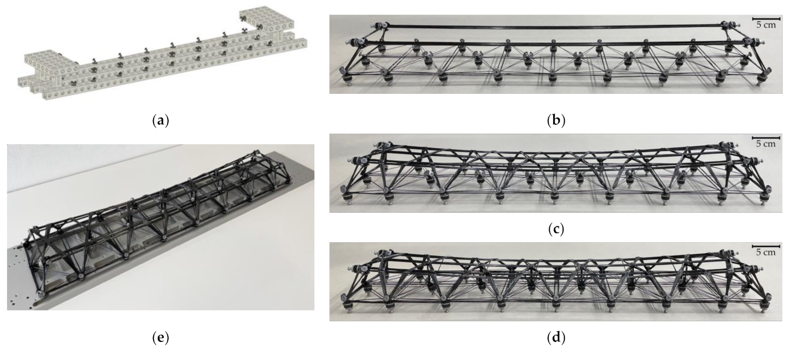
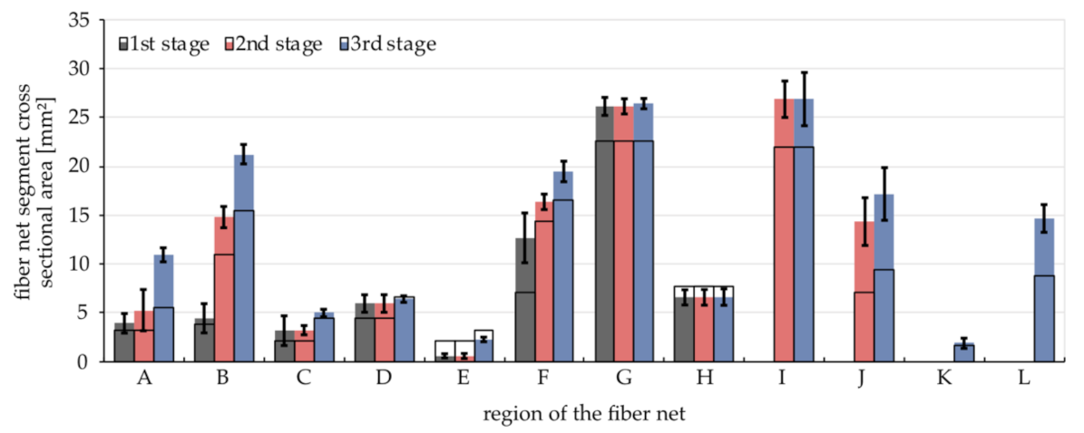
3.3. Multi-Stage CFW Process

For the production, Teijin Tenax-J UMS45 F22 12K [56] carbon fiber with 385 tex at 1.83 g/cm3 and MGS LR635, MGS LH635, and MGS LH637 [57] epoxy resin by Hexion was used in a 100:10:20 ratio. The fiber was selected because of its comparatively high tensile modulus of 425 GPa. To achieve the highest possible dimensional accuracy of the CFRP component, neither curing the component on the metallic winding fixture nor tempering of the demolded component in an oven was permissible. The aluminum frame could warp due to the high coefficient of thermal expansion, or the CFRP component could distort because of its inhomogeneous material distribution. Consequently, the resin was selected to achieve the highest possible stiffness without temperature treatment. As this resin requires several hours to cure, the time between winding sessions was correspondingly long. An application that allows a fast-curing resin could achieve better cycle times.
The utilized winding equipment was state-of-the-art, except for a modular winding fixture (Figure 12a), which was used to mount the winding pins. It helps to shorten preparation times, maintains relatively high geometrical accuracy, and can be reconfigured easily but restricts the position of the winding pin to a predefined pattern. In the first stage, the lower region was completed, and the two outer tension cords in the upper region were fabricated (Figure 12b). After the first curing, the winding fixture was removed, and in the second stage, the central tension cords in the top and the lateral diagonal struts were wound (Figure 12c). In the third stage, the inner struts were wound (Figure 12d). Finally, the component was mounted onto the aluminum base plate (Figure 12e).
After winding a stage, occasionally, rovings within a segment did not form a coherent bundle. This results mainly from deformations of the fiber net during the stage causing tension loss. To establish a force flow between the rovings, these rovings must be locally bound together with a polytetrafluoroethylene yarn. The yarn can be removed after curing the resin.
The digital design tool allows predicting the material consumption for each production step (Figure 13). From this, the cross-sectional area of each segment of the fiber net can be estimated and used to feed the framework analysis. The FVR is a determining parameter for this calculation and must be estimated a priori. For this, several interrelationships can be used. One of them is deriving it from the fiber and resin parameters and the cross-sectional area at the winding tool nozzle [33]. After each stage, the actual cross-sectional area of each segment was measured by a caliper (Figure 13). The rectangular area obtained by the width and height of the bundles does not represent the cross-sectional area well. A better representation is given by an ellipse or alternatively by a correction factor of π/4. The difference between the caliper measurements and the prediction results from a local variation in FVR, internal and external voids, and overestimation due to the rugged fiber bundle surface. The standard deviation of the caliper measurements is also predominantly dominated by an irregular division of the fiber bundle into individual bundles.
Another method to access the FVR and material consumption of the component is by measuring the resin consumption and total mass of the component (Table 3). This should only be used if negligible amounts of resin are lost during fabrication. From the mass of additional elements, such as winding pins, the composite mass can be calculated, which entails the resin and fiber mass. From this, the FVR can be calculated.
It can be observed that there is an increase in the measured FVR over the three stages, while the predicted FVR lies in between the extremes of the measured FVR. The increase may be a result of the angular position of the winding tool in relation to the free-spanning fiber during the winding, as higher angles cause lower FVR [33]. The interaction between the winding tool and roving is determined by the winding setup, winding syntax, and trajectory creation method. Based on the linear density of the fiber material, the total fiber length can be calculated and compared to the winding path length of the design tool. This can also be used as a quality control measure to monitor the compliance of the winding plan.

3.4. Mechanical Evaluation

To evaluate the structural performance of the component, two stiffness measurements were conducted. One to measure individual nodes to identify deviations in the fiber net and another measurement to evaluate the stiffness increase of the aluminum base plate by the fiber-composite structure as well as the performance of the assembled component in relation to the state-of-the-art steel plate reference design. In both cases, several defined forces were applied, and the deformation was measured by one or two dial indicators. This was translated into a spring stiffness.
For the first stiffness evaluation (Figure 14a) on individual winding pins, the fiber-composite structure was mounted to the winding fixture only at nodes 1, 2, 8–12, and 18–20 (Figure 10a). Single winding pins in region A (Figure 11c) were pulled upwards using a spring scale in the force range up to 50 N. On average, spring stiffness of 90.5 ± 23.2 N/mm was measured for an individual pin. Lower values around 75 N/mm were found in the middle, and higher stiffness up to 140 N/mm at the sides. This trend was expected as no pins were fixed in the center, but significant differences in stiffnesses between the front and rear winding pin cluster of region A could be found. This is another quality control measure for monitoring the compliance of the winding plan and for identifying hidden damage or kissing bonds. This approach allows easily localizing weak points, unlike an eigenfrequency measurement by, for example, a laser vibrometer.
For the second stiffness evaluation (Figure 14b) on the component level, the aluminum base plate was supported at its assembly interfaces. The orientation was upside down, neglecting the force of gravity. In a 3-point bending configuration, the plate was loaded in the center (Figure 9a). By installing the fiber-composite structure using all lower winding pins, the stiffness of the aluminum base plate could be increased by a factor of 1.76 in the covered force range up to 100 N. The mass-specific bending stiffness was increased by a factor of 2.5, although the stiffness of the state-of-the-art steel plate reference design remained 81% higher in absolute terms. The absolute mass of the total component in this design was 22% of the original steel component. Of the 4.13 kg component mass, only 0.35 kg is allocated to the fiber-composite structure, including the winding pins with 0.19 kg.

4. Discussion

This study focused on several key aspects to further develop the coreless filament winding process. First, the deployment of a fiber-composite/metal–hybrid concept in an engineering application; second, the implementation of multi-stage winding; and third, the development of a process-specific digital design and management tool that supports all project phases.
The hybrid material and process concept made it possible to combine the individual advantages. The conventionally manufactured metallic components allowed the subsequent machining to obtain the needed tolerances, while the LPBF winding pins enabled tolerance compensation during the assembly, and the CFW structure introduced high mass-specific stiffnesses into the hybrid component. The hybrid approach could significantly increase the mass-specific stiffness, while an application-specific trade-off between overall mass reduction and total component stiffness must be found individually.
The mechanical performance of the hybrid component depends on the interface between the fiber-composite and metal constituents. In addition, the novel winding pin design allows a more three-dimensional shape of the fiber net without introducing performance-reducing fiber kinks. While the geometric deviations prove to be sufficiently small, the surface roughness of the untreated winding pins could be an obstacle for robotic CFW. Sandblasting could help to improve fiber deposition quality but seems to be economically reasonable only for a smaller number of winding pins, while barrel tumbling primarily affects the exposed surfaces of the pins that are not process relevant.
The introduction of multi-stage winding into CFW simplifies the fabrication process. Despite the division of the demonstration winding into several stages, a deformation of the fiber net produced in the first stage was not completely prevented as nodes 27, 42, 44, and 59 were not fixed during the second stage. If the winding fixture remained attached, the deformation could be further decreased, but it would hinder the winding process in later stages. For the same reason, the winding pins in region C were lifted during the winding of stage 3. At what stage the winding fixture needs to be removed must be decided based on the tolerances and fabrication capabilities. The staging allows the designer increased control over the evolving shape of the component during manufacturing. Thus, the target geometry can be achieved more accurately, resulting in a better match with the digital object model and the simulative predictions. For applications where the achievement of the target geometry depends on this gradual deformation of the fiber net during winding, multi-stage winding offers no advantage.
Multi-stage winding includes further process-related advantages. Errors only affect the current sub syntax and not the entire component. This reduces the number of incorrect components and makes it easier to correct errors while still in production. Errors occur less frequently because the manufacturer must maintain concentration over a shorter period, which is not relevant for robotic winding. Multi-stage winding also allows the use of resins with a shorter pot life, which increases the material selection options. Furthermore, the component can be taken off the winding fixture after the first stage has been wound and cured, simplifying subsequent handling, and reducing cycle times if winding fixture availability is critically limited. A further advantageous aspect of multi-stage winding could be that the first stages of a component are designed to be representative of all further stages and that the component is tested after these first stages. This would allow calibrating simulations with the component-specific values and avoid having to revert to experience with other components. The simulative reproduction of the multi-stage winding process would also make repairs and subsequent reinforcements of CFW structures more understandable. Multi-stage winding may also be combined with multi-material winding.
The developed process-orientated design and management tool acts as a data framework to digitally represent CFW structures. All object data are saved in human-readable form. As the tool is custom-coded, there is full control over the object model and the used methods, which can be customized locally to the individual application scenario. It is intended that data sets can be updated during different project phases, and it distinguishes the data according to their origin (estimation, simulation, measurement). The functionalities of the CFW design tool were demonstrated in the case study, but in its current form, it is primarily a data framework that still offers potential for further methods, object attributes, or even level of details to be included.
Possible aspects to be included in the future, many of which are currently the subject of research, could be a more precise estimation of the winding pin capacity, the automated generation of winding trajectories, including the robot code, topology, and syntax design methods operated by artificial intelligence that do not rely that on human interaction, inclusion of adjacent parts such as the winding fixture or winding pins, simulation methods that include the wrapping zones and crossing points physically correctly, and fiber–fiber interaction simulation methods depending on the fiber tension during winding. Finally, it would be useful to have a user interface that directly embeds the visualizations, which also still have the potential to be scientifically developed further. Because the tool is research-oriented, it cannot be compared to industrial products in terms of feature set and maintenance, but it was designed specifically for CFW applications, so it is in accordance with the CFW design language and allows a faster and more natural way of interaction.

5. Conclusions

Several interrelated research aspects on coreless filament winding were investigated in the context of a case study in a mechanical engineering application, which demonstrated the functionalities of the digital design tool and validated the synergistic combination of CFW with LPBF and conventional manufacturing methods. This hybrid design approach resulted in an increase in mass-specific stiffness of the case study object and a beneficial combination of several material systems. This could only be achieved by novel winding pins made by additive manufacturing, which prevented geometrical limitations in the fiber net design as they could be customized to their position within the component. The increase in design freedom provided by the pins could only be harnessed because of the digital design tool.
The object-oriented tool helps to design, analyze, visualize, and collect the winding objects in a database in a curated form that operates non-destructively on all levels of detail. It allows to protocol the fabrication and therefore needs to track the origin of the object parameters throughout the project. The digital design tool requires an accurate digital representation of the real structure for reliable analysis and predictions. One approach demonstrated in the case study to improve the digital representation was multi-stage winding. Whereas within a winding stage, the deformation of the fiber net by fiber–fiber interaction takes place, it can be prevented or reduced between winding stages. Multi-stage winding also increases winding fixture availability, simplifies the fabrication process, reduces human errors, and limits the effect of errors to a single stage.
Digital planning is key to an efficient design process for interacting processes and material system in lightweight design. As a foundation, the developed methods provide the holistic digital capturing of the winding objects, which is key to gaining control over the CFW process and optimizing its efficiency for serial production in the future. Only a process with such characteristics may enter an industrial application in engineering.

Author Contributions

Conceptualization, P.M. and R.M.; methodology, P.M., R.M., E.D., C.O. and R.K.; software, P.M.; validation, M.M. and G.T.G.; formal analysis, P.M., R.M. and E.D.; investigation, P.M., R.M., E.D., C.O. and R.K.; resources, M.M. and G.T.G.; data curation, P.M., R.M., E.D., C.O. and R.K.; writing—original draft preparation, P.M. and C.O.; writing—review and editing, R.M., E.D., C.O. and R.K.; visualization, P.M., R.M. and R.K.; supervision, M.M. and G.T.G.; project administration, M.M.; funding acquisition, P.M., R.M. and M.M. All authors have read and agreed to the published version of the manuscript.

Funding

This research was funded by the Ministry of Science, Research and the Arts of Baden-Wuerttemberg (MWK, Ministerium für Wissenschaft, Forschung und Kunst Baden-Württemberg).

Data Availability Statement

The data presented in this study are available on request from the corresponding author. The data are not publicly available due to third party restrictions.

Acknowledgments

The authors would like to express their gratitude towards their fellow re- searchers Peter Hoffrogge, Thomas Götz, Daniel Müller, and Robert Wegner.

Conflicts of Interest

The authors declare no conflict of interest. The funders had no role in the design of the study; in the collection, analyses, or interpretation of data; in the writing of the manuscript, or in the decision to publish the results.

Appendix A

Table A1. Predefined attributes of a winding object in groups: geometrical parameters, mechanical testing data, fiber-optical sensor data, fiber material, resin material, winding and hooking syntaxes, winding pin attributes, production and physical parameters.
Attribute (self.)Data Type *DimensionDescription
IDstr-name of the winding object
graphdict of int: list of int-connections between nodes
pathlist of int-nodes along the fiber path
coordinatesdict of int: tuple of floatself.unitx, y, and z coordinates of nodes
positionsdict of str: tuple of floatself.unitx, y, and z coordinates of control points
groupdict of str: str-groups of the nodes (color names)
forcesdict of int: tuple of floatkNx, y, and z components of external forces acting on nodes
test_datetimedatetime.datetimedate, timelocal date and time of the start of the mechanical test
test_typestr-type of mech. test: tension, compression, or 3P-bending
test_commentstr-special test parameters or settings and observations
test_speedfloatmm/minspeed of the cross head (if constant, otherwise: 0)
test_sampling_ratefloatHzsamples per seconds of the universal testing machine
compression_flagbool-if true, mirrors the force-displacement-graphs
test_datapandas.dataframemultipledata of mech. test: time, force, displacement, stress, and strain
test_bundle_thicknesslist of floatmmmeasured width and depth of the relevant bundle(s)
test_bundle_areafloatmm2area of relevant bundle(s), e.g., obtained by micro-sections
test_bundlesint-number of bundles in the tested cross-section
area_zerofloatmm2initial cross-section area of the component
length_zerofloatmminitial length of the test specimen in testing direction
FOS_pathlist of int-nodes along the FOS path
FOS_pathlengthdict of str: floatmlength of FOS path (theor. / real and simple/discretized)
FOS_datapandas.dataframemultipleFOS data set (strain over time and fiber length)
FOS_seclist of floatsectimesteps of the FOS measurements
FOS_locationslist of floatmlocations of the sampling points along the FOS
FOS_commentstr-special test parameters or settings and observations
FOS_sensorstr-type of used FOS
FOS_sensor_IDstr-ID of the FOS as given by the FOS system
FOS_sensor_namestr-description of the FOS as given by the FOS system
FOS_startfloatmposition along the FOS where the measurement zone starts
FOS_endfloatmposition along the FOS where the measurement zone ends
FOS_infloatmposition along the FOS where it enters the component
FOS_outfloatmposition along the FOS where it leaves the component
FOS_datetimedatetime.datetimedate, timedate and time of the start of the FOS measurement (UTC)
FOS_channelint-channel the FOS was attached to
FOS_pitchfloatmmdistance between two adjacent sampling points
FOS_ratefloatHzsampling rate of the FOS system
FOS_markersdict of str: list of floatmrelevant sections along the FOS
FOS_pricefloat€/mprice of the FOS
fiber_productstr-name of the fiber product
fiber_typestr-type of the fiber, e.g., carbon, glass, or flax
kint1000number of the filaments, e.g., 6, 12, 24, or 48
texintg/kmlinear density of the fiber roving or yarn
TPMfloat1/mnumber of twists per meter
fiber_densityfloatg/cm3density of the dry fiber material
fiber_tensile_modulusfloatGPatensile modulus of the dry fiber
fiber_tensile_strengthfloatMPatensile strength of the dry fiber
fiber_max_elongationfloat%elongation at failure
filament_diameterfloatµmaverage diameter of a single filament/fiber
roving_areafloatmm2cross-sectional area of the dry fiber roving or yarn
fiber_pricefloat€/gprice of the fiber product
resin_productstr-name of the resin product
mixing_ratiodict of str: float%ingredients of the resin and their mixing ratios
viscosityintmPa *sviscosity of the mixed resin at room temperature
potlifeintminpot life of the mixed resin
resin_densityfloatg/cm3density of the cured resin
resin_correction_factorfloat%correction factor for the pyrolysis [49]
curing_templist of int°Ctemperature level for resin curing and tempering
curing_minlist of intminduration of the steps to cure the resin
resin_pricefloat€/gprice of the resin product
subsyntaxdict of str: list of int-named sequences of nodes
syntaxlist of str or int-list containing keys of the sub syntax or the node sequence
pathlengthdict of str: floatunitlength of fiber path (theor. / real and simple/discretized)
resolutiondict of tuple of int: int-number of bundles at each edge
bundles_diameterdict of tuple of int: floatmmtheoretical diameter of bundles at each edge and winding pin
orientationdict of int: tuple of float-unit vectors of the axial direction of each winding pin
hookinglist of int-number of hookings performed on each winding pin, see [44]
pre_start_nodeint or list of floatmultipleadditional start node (int/-) or coordinates (list of float/unit)
post_end_nodeint or list of floatmultipleadditional end node (int/-) or coordinates (list of float/unit)
pin_namestr-name of the winding pin
pin_typestr-type of the winding pin, e.g., sleeve–washer combination
pin_inner_diameterfloatmminner diameter of the winding pin
pin_outer_diameterfloatmmouter diameter of the winding pin
pin_sleeve_diameterfloatmminner diameter of the sleeve
pin_heightfloatmmheight of the sleeve
pin_massfloatgmass of the winding pin parts that remain in the component
pin_materialstr-material of the winding pin parts that remain in the component
pin_boltstr-nominal diameter of the center bolts thread
pin_capacityfloatmmcapacity of the winding pin expressed as a diameter
pin_pricefloatprice of the single-use parts of the winding pin
makerlist of str-operator name(s)
robotstr-robot type or serial number or “manual” keyword
toolstr-name of the used winding tool
tool_capacityfloatmlvolume of resin that the tool can hold without reloading
nozzle_diameterfloatmmdiameter of the characteristic tool opening
production_datedatetime.datedatedate of winding
production_commentstr-special production parameters or settings and anomalies
production_tempfloat°Ctemperature of the production environment
production_humidityfloat%relative humidity of the production environment
curingpandas.dataframemultipletemperature curve of the curing process
unitstrmultipledefines the unit of length of the winding object model
photoslist of str-file names of pictures or videos related to the winding object
composite_massdict of key: floatgmass of the composite of the component (theor., real)
component_massdict of key: floatgmass of the whole component (keys: theor., real)
composite_volumefloatcm3volume of the composite of the component (key set by mass)
component_volumefloatcm3volume of the whole component (key set by mass)
composite_densityfloatg/cm3density of the composite of the component (key set by mass)
component_densityfloatg/cm3density of the whole component (key set by mass)
component_pricedict of key: floatmaterial price of the whole component (keys: theor., real)
pyrolysisdatetime.datedatedate of the pyrolysis measurement
FVRfloat%characteristic fiber volume ratio of the winding object
FMRfloat%characteristic fiber mass ratio of the winding object
* Data types are indicated as follows: integer (int), floating-point numbers (float), boolean (bool), string (str), list (list), tuple (tuple), and dictionary with key and value (dict of key: value).
Table A2. Predefined methods of the winding class.
Type *NameDescription
self__len__returns the number of missing attributes of the winding object
self__str__returns all variables of the winding object
selfadd_FOS_markeradds a marker to FOS data
selfadd_FOS_markers_equallyadds equally spaced markers
selfadd_edgeadds one or multiple edges to the graph
selfadd_nodeadds a node to the winding object
selfadd_random_pointsadds random points inside a single or multiple boxes
selfadd_subsyntaxadds a node sequence to the sub syntaxes
selfadd_winding_originadds a winding origin for the windabiltiy check
clscheck_catalog_fiberreturns the control string for a fiber of the catalog
clscheck_catalog_pinreturns the control string for a winding pin of the catalog
clscheck_catalog_pyrolysisreturns the control string for a pyrolysis measurement of the catalog
clscheck_catalog_resinreturns the control string for a resin of the catalog
clscheck_catalog_toolreturns the control string for a fiber of the catalog
selfcheck_eulerianchecks if the graph is Eulerian (Hierholzer’s algorithm)
selfcheck_inside_boxchecks if a point is inside a box
selfcheck_path_in_graphchecks if the path is a subset of the graph
selfcheck_path_is_cyclechecks if the first and last node within the path are the same
staticcheck_versionschecks the versions of the included Python packages
staticcirclereturns the coordinates of a circle
staticclosest_value_from_listreturns the closest value to the given value that is part of a list
selfconnect_nearby_nodesconnects all nodes with their closest nodes at a given number of edges per node
selfconnect_nodes_by_distanceconnects all nodes within a given Euclidian distance
staticconvert_lengthconverts values of length between µm, mm, cm, dm, m, and km
staticcylinderreturns the coordinates of a cylinder
selfdiscretize_pathdiscretizes a winding path at a winding pin
staticevaluate_matrix_similarityreturns the number of changes necessary to make both matrixes the same
clsevaluate_pyrolysisevaluates pyrolysis data and returns fiber volume ratio and fiber mass ratio
selfexport_FOS_to_parquetexports FOS data as a parquet file (slow but small file)
selfexport_FOS_to_pickleexports FOS data as pickle file (fast but large file)
selfextend_FOS_pathextends the FOS path around sleeve points
selffind_all_intersectionsfinds all intersections in a graph
staticfind_averagereturns the weighted average of values
selffind_boxfinds the corner points of a box from a given center point
selffind_breaking_lengthreturns the breaking length in km of the dry fiber material
selffind_dimensionsreturns the overall dimensions of the winding object
selffind_edge_loadperforms a framework analysis of the winding object
selffind_equidistant_pointsreturns a list of equidistant points between two nodes
selffind_eulerianreturns a Eulerian path or cycle of the graph
selffind_hookingsreturns a dictionary with the hooking condition parameter [44] per node in winding order
selffind_line_intersectionfinds the intersection point of two lines between nodes
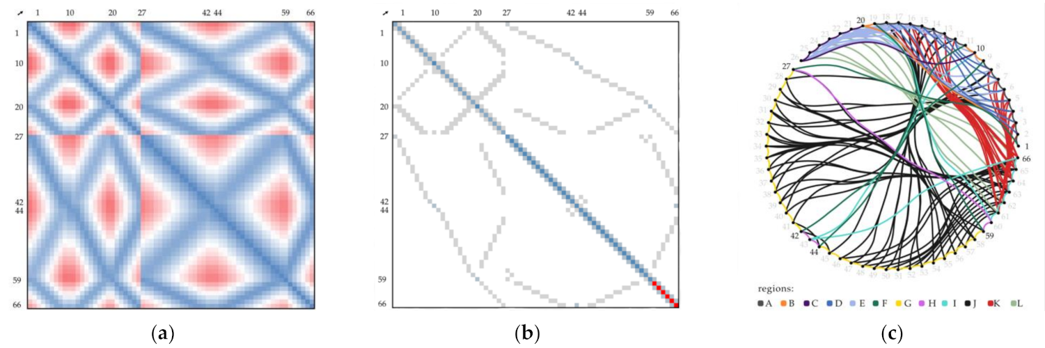
selffind_matrix_adjacencyreturns the adjacency matrix for the graph
selffind_matrix_bundles_diameterreturns the bundles diameter matrix
selffind_matrix_distancereturns the distance matrix ignoring the graph
selffind_matrix_resolutionreturns the resolution matrix
selffind_pin_saturationreturns the theoretical occupancy of each winding pin in percent
selffind_points_around_sleevereturns points around a winding sleeve
clsfind_resin_correction_factorreturns the resin correction factor used in the pyrolysis [49]
selffind_resolution_distributionreturns the undirected winding resolution distribution
selffind_shortest_pathreturns the shortest path between two given nodes
selffind_triangle_line_intersectionreturns the position of a line intersecting a triangle given by three points
selffind_unit_vectorreturns the unit vector between two nodes or positions
selfimport_FOS_from_parquetimports FOS data from a gzip file
selfimport_FOS_from_pickleimports FOS data from a gzip file
selfimport_FOS_from_tsvimports FOS data from a tsv file created by the FOS system
selfimport_all_from_csvimports the graph, groups, and coordinates from csv file
selfimport_coordinates_from_csvimports the node coordinates from a csv file
selfimport_curingimports the curing temperature curve from a csv file
selfimport_forces_from_csvimports the forces acting on the nodes from a csv file
selfimport_graph_from_csvimports the graph from a csv file
selfimport_group_from_csvimports the color groups of the nodes from a csv file
selfimport_orientation_from_csvimports the winding pin orientations from a csv file
selfimport_subsyntax_from_csvimports the sub syntaxes from a csv file
selfimport_test_from_txtimports mechanical testing data from a txt file created by the universal testing machine
selfisolate_nodeisolates a node
clslearn_fiberadds a fiber to the fiber catalog of the class
clslearn_pinadds a winding pin to the winding pin catalog of the class
clslearn_pyrolysisadds a pyrolysis measurement to the pyrolysis catalog of the class
clslearn_resinadds a resin to the resin catalog of the class
clslearn_tooladds a tool to the tool catalog of the class
selflist_all_pathslists paths between two nodes that does not contain cycles or loops
staticlist_colorslists the predefined colors
selflist_edges_alllists all possible edges ignoring the graph
selflist_edges_graphlists all edges within the graph
selflist_edges_pathlists the edges along the path
clslist_methodslists all methods
selflist_nodeslists all nodes in the graph
clslist_objectslists all winding objects of the class
selflist_path_angleslists all angles at nodes along the path
selflist_path_nodeslists the nodes traveled by the path, including how often they have been visited
selflist_subsyntaxreturns a list of all sub syntaxes
selflist_vectors_at_nodelists the unit vectors of a node
selfmodify_FOS_datalimits, crops the array in time or space, smooths FOS data, and replaces NaNs by zeros
selfmove_nodeshifts or relocates a node
selfnodesreturns the number of nodes in the graph or coordinates
selfparametersreturns a list of all parameters of the winding object
selfplot_2Dplots the winding object in 2D
selfplot_3Dplots the winding object in 3D
selfplot_FOSplots the FOS data as surface plot, matrix plot, or 2D plot
selfplot_FOS_histogramplots a histogram of the FOS data
selfplot_barplots a bar chart of a list
selfplot_curingplots curing data
selfplot_matrixplots a matrix
selfplot_testplots the mech. test data as force-displacement or stress-strain diagram
staticproject_vec_on_planeprojects a vector onto a plane
selfremove_edgeremoves a specific edge
selfremove_loopsremoves all loops in the graph and/or path
selfremove_noderemoves a specific node
selfrename_noderenames a node
selfrepeat_pathrepeats the path
selfrotate_noderotates a node or list of nodes around a point and vector in counterclockwise direction
staticrotation_matrixreturns the rotation matrix of a counterclockwise rotation about the axis
staticround_downrounds down a number at a decimal
staticround_uprounds up a number at a decimal
selfset_FVRsets the FVR value of the winding object from the pyrolysis catalog or overrides it manually
selfset_bundle_diametersets the bundles diameter and the winding pin occupation
selfset_component_masssets the component mass of the winding object
selfset_component_pricesets the price of the component including sleeves and FOS
selfset_component_volumesets the volume of the component measured by Archimedes’ principle
selfset_composite_masssets the composite mass of the component
selfset_edge_midpointssets the positions of the midpoints of all edges of the graph and adds them to self.positions
selfset_fibersets the fiber material of the winding object based on the fiber catalog of the class
selfset_forceset the force of a node
selfset_path_from_syntaxsets the path based on self.syntax
selfset_pathlengthcalculates the theoretical length of the fiber or FOS path
selfset_physical_parametersset the composite and component mass as well as the component price
selfset_pinsets the resin material of the winding object based on the resin catalog of the class
selfset_pin_orientationsets the winding pin orientation by a path segment
selfset_production_parameterssets the parameters of the production or overrides them
selfset_resinsets the resin material of the winding object based on the resin catalog of the class
selfset_resolutionsets the resolution (bundles per segment) of the winding object
selfset_roving_areasets the cross-sectional area in mm2 of a dry roving by filament number or linear density
selfset_sleeve_pointssets the in and out points of a node with given sleeve parameters
selfset_syntaxsets the syntax of the winding object
selfset_test_parameterssets the parameters of the mechanical test or overrides them
selfset_toolsets the winding tool based on the tool catalog of the class
selfset_unitsets the unit of length for the node coordinates
selfsimple_anglereturns the included angle at the left node of a list of three nodes
selfsimple_distancereturns the Euclidean distance between two nodes
clstabulate_objectsreturns a table of selected parameters of all winding objects of the class
clstabulate_pyrolysisreturns a table of selected parameters of all pyrolysis measurements of the class
clstimer_returnprints a timer
clstimer_startstarts a timer
clstimer_stopstops a timer
selfwalksets a path based on the graph and the selected method of traveling
staticwater_densityreturns the density of water depending on the water temperature
selfxyz_posreturns the x, y, and z coordinates of a node or position
* Method types are indicated as follows: depended on the object (self), depending on the class (cls), and static methods (static).
Table A3. Winding syntax of the demonstration component.
StageSub SyntaxRegions *RepetitionsSequence
11A, B20, 1, 2, 3, 4, 5, 6, 7, 8, 9, 10, 11, 12, 13, 14, 15, 16, 17, 18, 19, 20
2A, B, D20, 1, 2, 18, 2, 3, 17, 3, 4, 16, 4, 5, 15, 5, 6, 14, 6, 7, 13, 7, 8, 12, 8, 9, 10, 11, 12, 8, 12, 13, 7, 13, 14, 6, 14, 15, 5, 15, 16, 4, 16, 17, 3, 17, 18, 2, 18, 19, 20
3A, B, C20, 21, 22, 23, 24, 25, 26, 10, 11, 12, 13, 14, 15, 16, 17, 18, 19, 20, 1, 2, 3, 4, 5, 6, 7, 8, 9, 10, 26, 25, 24, 23, 22, 21, 20
4E20, 18, 21, 3, 22, 16, 23, 5, 24, 14, 25, 7, 26, 12, 10, 8, 26, 13, 25, 6, 24, 15, 23, 4, 22, 17, 21, 2, 20
bridgeB20, 19
5F19, 59, 19
bridgeB, F, G, H19, 59, 58, 57, 56, 55, 54, 53, 52, 51, 50, 49, 48, 47, 46, 45, 44, 11, 10, 9, 42, 43, 44
6F44, 11, 44
7G20×44, 45, 46, 47, 48, 49, 50, 51, 52, 53, 54, 55, 56, 57, 58, 59, 58, 57, 56, 55, 54, 53, 52, 51, 50, 49, 48, 47, 46, 45, 44
bridgeH44, 43, 42
8F42, 9, 42
9H42, 43, 44, 43, 42
10G20×42, 41, 40, 39, 38, 37, 36, 35, 34, 33, 32, 31, 30, 29, 28, 27, 28, 29, 30, 31, 32, 33, 34, 35, 36, 37, 38, 39, 40, 41, 42
bridgeG42, 41, 40, 39, 38, 37, 36, 35, 34, 33, 32, 31, 30, 29, 28, 27
11H27, 60, 59, 60, 27
12F27, 1, 27
bridgeB27, 1, 20
213B, F, J10×20, 1, 27, 58, 18, 57, 61, 30, 3, 31, 62, 54, 16, 53, 63, 34, 5, 35, 64, 50, 14, 49, 65, 38, 7, 39, 66, 46, 12, 45, 42, 9, 10, 11, 44, 41, 8, 40, 66, 47, 13, 48, 65, 37, 6, 36, 64, 51, 15, 52, 63, 33, 4, 32, 62, 55, 17, 56, 61, 29, 2, 28, 59, 19, 20
14I20×20, 60, 61, 62, 63, 64, 65, 66, 43, 10, 43, 66, 65, 64, 63, 62, 61, 60, 20
13B, F, J20, 1, 27, 58, 18, 57, 61, 30, 3, 31, 62, 54, 16, 53, 63, 34, 5, 35, 64, 50, 14, 49, 65, 38, 7, 39, 66, 46, 12, 45, 42, 9, 10, 11, 44, 41, 8, 40, 66, 47, 13, 48, 65, 37, 6, 36, 64, 51, 15, 52, 63, 33, 4, 32, 62, 55, 17, 56, 61, 29, 2, 28, 59, 19, 20
315B, F, J, L20, 1, 27, 58, 18, 57, 61, 21, 61, 30, 3, 31, 62, 22, 62, 54, 16, 53, 63, 23, 63, 34, 5, 35, 64, 24, 64, 50, 14, 49, 65, 25, 65, 38, 7, 39, 66, 26, 66, 46, 12, 45, 42, 9, 10, 11, 44, 41, 8, 40, 66, 26, 66, 47, 13, 48, 65, 25, 65, 37, 6, 36, 64, 24, 64, 51, 15, 52, 63, 23, 63, 33, 4, 32, 62, 22, 62, 55, 17, 56, 61, 21, 61, 29, 2, 28, 59, 19, 20
16B, F, J, K, L20, 1, 27, 58, 18, 57, 21, 61, 21, 30, 3, 31, 22, 62, 22, 54, 16, 53, 23, 63, 23, 34, 5, 35, 24, 64, 24, 50, 14, 49, 25, 65, 25, 38, 7, 39, 26, 66, 26, 46, 12, 45, 42, 9, 10, 11, 44, 41, 8, 40, 26, 66, 26, 47, 13, 48, 25, 65, 25, 37, 6, 36, 24, 64, 24, 51, 15, 52, 23, 63, 23, 33, 4, 32, 22, 62, 22, 55, 17, 56, 21, 61, 21, 29, 2, 28, 59, 19, 20
1A, B20, 1, 2, 3, 4, 5, 6, 7, 8, 9, 10, 11, 12, 13, 14, 15, 16, 17, 18, 19, 20
2A, B, D20, 1, 2, 18, 2, 3, 17, 3, 4, 16, 4, 5, 15, 5, 6, 14, 6, 7, 13, 7, 8, 12, 8, 9, 10, 11, 12, 8, 12, 13, 7, 13, 14, 6, 14, 15, 5, 15, 16, 4, 16, 17, 3, 17, 18, 2, 18, 19, 20
4E20, 18, 21, 3, 22, 16, 23, 5, 24, 14, 25, 7, 26, 12, 10, 8, 26, 13, 25, 6, 24, 15, 23, 4, 22, 17, 21, 2, 20
17C20, 21, 22, 23, 24, 25, 26, 10, 26, 25, 24, 23, 22, 21, 20
1A, B20, 1, 2, 3, 4, 5, 6, 7, 8, 9, 10, 11, 12, 13, 14, 15, 16, 17, 18, 19, 20
* Regions of the fiber net: (A) longer lower outer edge; (B) shorter lower outer edge; (C) lower center rib (section 10–20); (D) lower transverse struts (e.g., section 2–18); (E) lower diagonal ribs; (F) raised outer edges of corners; (G) longer upper outer edge; (H) shorter upper outer edge; (I) upper center rib (section 10–20); (J) lateral cross-bracing; (K) diagonal inner struts; (L) vertical inner struts.

References

  1. Bakis, C.E.; Bank, L.C.; Brown, V.L.; Cosenza, E.; Davalos, J.F.; Lesko, J.J.; Machida, A.; Rizkalla, S.H.; Triantafillou, T.C. Fiber-Reinforced Polymer Composites for Construction—State-of-the-Art Review. J. Compos. Constr. 2002, 6. [Google Scholar] [CrossRef] [Green Version]
  2. Utsunomiya, S.; Kamiya, T.; Shimizu, R. Development of CFRP mirrors for space telescopes. In Proceedings of the Volume 8837—Material Technologies and Applications to Optics, Structures, Components, and Sub-Systems, SPIE Optical Engineering and Applications, San Diego, CA, USA, 25–29 August 2013. [Google Scholar] [CrossRef]
  3. Galehdar, A.; Nicholson, K.J.; Callus, P.J.; Rowe, W.S.T.; John, S.; Wang, C.H.; Ghorbani, K. The strong diamagnetic behaviour of unidirectional carbon fiber reinforced polymer laminates. J. Appl. Phys. 2012, 112, 113921. [Google Scholar] [CrossRef]
  4. Wang, W.X.; Takao, Y.; Matsubara, T. Galvanic Corrosion-Resistant Carbon Fiber Metal Laminates. In Proceedings of the 16th International Conference on Composite Materials, ICCM-16—“A Giant Step Towards Environmental Awareness: From Green Composites to Aerospace” (ICCM International Conferences on Composite Materials), Kyoto, Japan, 8–13 July 2007. [Google Scholar]
  5. Pimenta, S.; Pinho, S.T. Recycling carbon fibre reinforced polymers for structural applications: Technology review and market outlook. Waste. Manag. 2011, 31, 378–392. [Google Scholar] [CrossRef] [PubMed] [Green Version]
  6. Savage, G.; Oxley, M. Damage Evaluation and Repair of Composite Structures. An. Mecánica Fract. 2008, 25, 758–768. [Google Scholar]
  7. Heuer, H.; Schulze, M.; Pooch, M.; Gäbler, S.; Nocke, A.; Bardl, G.; Cherif, C.; Klein, M.; Kupke, R.; Vetter, R.; et al. Review on quality assurance along the CFRP value chain—Non-destructive testing of fabrics, preforms and CFRP by HF radio wave techniques. Compos. Part B Eng. 2015, 77, 494–501. [Google Scholar] [CrossRef]
  8. Das, S. Life cycle assessment of carbon fiber-reinforced polymer composites. Int. J. Life Cycle Assess. 2011, 16, 268–282. [Google Scholar] [CrossRef]
  9. La Magna, R.; Waimer, F.; Knippers, J. Coreless Winding and Assembled Core—Novel fabrication approaches for FRP based components in building construction. Constr. Build. Mater. 2016, 127, 1009–1016. [Google Scholar] [CrossRef]
  10. Minsch, N.; Müller, M.; Gereke, T.; Nocke, A.; Cherif, C. 3D truss structures with coreless 3D filament winding technology. J. Compos. Mater. 2019, 53, 2077–2089. [Google Scholar] [CrossRef]
  11. Büchler, D.; Elsken, T.; Glück, N.; Sier, M.; Bludszuweit, S. Ultraleichte Raumzelle–Entwicklung von ultraleichten Großstrukturen in Faserverbund- und Hybridbauweise für den Schiffbau. In Statustagung Schifffahrt und Meerestechnik, 1st ed.; Forschungszentrum: Jülich, Germany, 2011; pp. 25–45. [Google Scholar]
  12. Prado, M. Skeletal composites: Robotic fabrication processes for lightweight multi-nodal structural components. Constr. Robot. 2020, 4, 217–226. [Google Scholar] [CrossRef]
  13. Duque Estrada, R.; Kannenberg, F.; Wagner, H.J.; Yablonina, M.; Menges, A. Spatial winding: Cooperative heterogeneous multi-robot system for fibrous structures. Constr. Robot. 2020, 4, 205–215. [Google Scholar] [CrossRef]
  14. Hunt, C.J.; Morabito, R.; Grace, C.; Zhao, Y.; Woods, B.K.S. A review of composite lattice structures. Compos. Struct. 2022, 284, 115120. [Google Scholar] [CrossRef]
  15. Dambrosio, N.; Zechmeister, C.; Bodea, S.; Koslowski, V.; Gil Pérez, M.; Rongen, B.; Knippers, J.; Menges, A. Towards an architectural application of novel fiber composite building systems—The BUGA Fibre Pavilion. In Proceedings of the 39th Annual Conference of the Association for Computer Aided Design in Architecture, Austin, TX, USA, 24–26 October 2019; ACADIA: Fargo, ND, USA, 2019; pp. 140–149. [Google Scholar]
  16. Bodea, S.; Dambrosio, N.; Zechmeister, C.; Gil Pérez, M.; Koslowski, V.; Rongen, B.; Dörstelmann, M.; Knippers, J.; Menges, A.; Kyjanek, O. BUGA Fibre Pavilion: Towards robotically-fabricated composite building structures. In Fabricate 2020; Burry, J., Sabin, J.E., Sheil, B., Skavara, M., Eds.; UCL Press: London, UK, 2020; pp. 234–243. [Google Scholar]
  17. Polini, W.; Sorrentino, L. Influence of winding speed and winding trajectory on tension in robotized filament winding of full section parts. Compos. Sci. Technol. 2005, 65, 1574–1581. [Google Scholar] [CrossRef]
  18. Arrabiyeh, P.A.; May, D.; Eckrich, M.; Dlugaj, A.M. An overview on current manufacturing technologies: Processing continuous rovings impregnated with thermoset resin. Polym. Compos. 2021, 42, 5630–5655. [Google Scholar] [CrossRef]
  19. Mindermann, P.; Bodea, S.; Menges, A.; Gresser, G.T. Development of an Impregnation End-Effector with Fiber Tension Monitoring for Robotic Coreless Filament Winding. Processes 2021, 9, 806. [Google Scholar] [CrossRef]
  20. Gil Pérez, M.; Zechmeister, C.; Kannenberg, F.; Mindermann, P.; Balangé, L.; Guo, Y.; Hügle, S.; Gienger, A.; Forster, D.; Bischoff, M.; et al. Computational co-design framework for coreless wound fibre-polymer composite structures. J. Comput. Des. Eng. 2022, in press. [Google Scholar]
  21. Quanjin, M.; Rejab, M.R.M.; Idris, M.S.; Kumar, N.M.; Merzuki, M.N.M. Robotic Filament Winding Technique (RFWT) in Industrial Application: A Review of State of the Art and Future Perspectives. Int. Res. J. Eng. Technol. 2018, 5, 1668–1676. [Google Scholar]
  22. Munro, M. Review of Manufacturing of Fiber Composite Components by Filament Winding. Polym. Compos. 1988, 9, 352–359. [Google Scholar] [CrossRef]
  23. Vasiliev, V.V.; Barynin, V.A.; Razin, A.F. Anisogrid composite lattice structures—Development and aerospace applications. Compos. Struct. 2012, 94, 1117–1127. [Google Scholar] [CrossRef]
  24. Sorrentino, L.; Anamateros, E.; Bellini, C.; Carrino, L.; Corcione, G.; Leone, A.; Paris, G. Robotic filament winding: An innovative technology to manufacture complex shape structural parts. Compos. Struct. 2019, 220, 699–707. [Google Scholar] [CrossRef]
  25. Bodea, S.; Zechmeister, C.; Dambrosio, N.; Dörstelmann, M.; Menges, A. Robotic coreless filament winding for hyperboloid tubular composite components in construction. Automat. Constr. 2021, 126, 103649. [Google Scholar] [CrossRef]
  26. Gil Pérez, M.; Rongen, B.; Koslowski, V.; Knippers, J. Structural Design, Optimization and Detailing of the BUGA Fibre Pavilion. Int. J. Space Struct. 2020, 35, 147–159. [Google Scholar] [CrossRef]
  27. Rongen, B.; Koslowski, V.; Gil Pérez, M.; Knippers, J. Structural optimisation and rationalisation of the BUGA fibre composite dome. In Proceedings of the IASS Annual Symposium—Structural Membranes—Form and Force, Barcelona, Spain, 7–10 October 2019. [Google Scholar]
  28. Bodea, S.; Mindermann, P.; Gresser, G.T.; Menges, A. Additive Manufacturing of Large Coreless Filament Wound Composite Elements for Building Construction. 3d Print. Addit. Manuf. 2021. [Google Scholar] [CrossRef]
  29. Gil Pérez, M.; Früh, N.; La Magna, R.; Knippers, J. Integrative structural design of a timber-fibre hybrid building system fabricated through coreless filament winding: Maison Fibre. J. Build. Eng. 2022, 49, 104114. [Google Scholar] [CrossRef]
  30. Mindermann, P.; Rongen, B.; Gubetini, D.; Knippers, J.; Gresser, G.T. Material Monitoring of a Composite Dome Pavilion Made by Robotic Coreless Filament Winding. Materials 2021, 14, 5509. [Google Scholar] [CrossRef] [PubMed]
  31. De Lima, A.S.; De Faria, A.R.; Faria, J.J.R. Critical Review of Displacement-Based Laminate Theories and Modeling Techniques. In Proceedings of the 4th Brazilian Conference on Composite Materials, Rio de Janeiro, Brazil, 22–25 July 2018. [Google Scholar] [CrossRef]
  32. Menges, A.; Knippers, J.; Wagner, H.J.; Zechmeister, C. Pilotprojekte für ein Integratives Computerbasiertes Planen und Bauen. In Baustatik–Baupraxis, 14th ed.; Bischoff, M., Scheven, M., Bastian, O., Eds.; University of Stuttgart: Stuttgart, Germany, 2020; pp. 67–79. [Google Scholar]
  33. Mindermann, P.; Gresser, G.T. Robotic 3D Deposition of Impregnated Carbon Rovings with Gradient Properties for Primary Structures. In Proceedings of the 69th International Astronautical Congress, Bremen, Germany, 1–5 October 2015. [Google Scholar]
  34. Cayley, A. A theorem on trees. Quart. J. Math. 1889, 23, 376–378. [Google Scholar]
  35. Dreißig, D.; Faßbänder, P.; Hindenlang, U. Simulation of carbon-roving-structures-extreme light and strong by filament wound reinforcement. In Proceedings of the 6th BETA CAE International Conference, Thessaloniki, Greece, 10–12 June 2015. [Google Scholar]
  36. Gil Pérez, M.; Rongen, B.; Koslowski, V.; Knippers, J. Structural design assisted by testing for modular coreless filament-wound composites: The BUGA Fibre Pavilion. Constr. Build Mater. 2021, 301, 124303. [Google Scholar] [CrossRef]
  37. Prashanth, S.; Subbaya, K.M.; Nithin, K.; Sachhidananda, S. Fiber Reinforced Composites—A review. J. Mater. Sci. Eng. 2017, 6, 1000341. [Google Scholar] [CrossRef] [Green Version]
  38. Hitzler, L.; Merkel, M.; Hall, W.; Öchsner, A. A Review of Metal Fabricated with Laser- and Powder-Bed Based Additive Manufacturing Techniques: Process, Nomenclature, Materials, Achievable Properties, and its Utilization in the Medical Sector. Adv. Eng. Mater. 2018, 20, 1700658. [Google Scholar] [CrossRef] [Green Version]
  39. Früh, N.; Knippers, J. Multi-stage filament winding: Integrative design and fabrication method for fibre-reinforced composite components of complex geometries. Compos. Struct. 2021, 268, 113969. [Google Scholar] [CrossRef]
  40. Shai, O.; Preiss, K. Graph theory representations of engineering systems and their embedded knowledge. Artif. Intell. Eng. 1999, 13, 273–285. [Google Scholar] [CrossRef]
  41. Wang, J.; Lu, M.; Belardo, F.; Randić, M. The anti-adjacency matrix of a graph: Eccentricity matrix. Discret. Appl. Math. 2018, 251, 299–309. [Google Scholar] [CrossRef]
  42. Zechmeister, C.; Bodea, S.; Dambrosio, N.; Menges, A. Design for long-span coreless wound, structural composite building elements. In Impact: Design with All Senses; Gengnagel, C., Baverel, O., Burry, J., Ramsgaard-Thomsen, M., Weinzierl, S., Eds.; Springer: Berlin, Germany, 2020; pp. 401–415. [Google Scholar]
  43. Mindermann, P.; Gil Pérez, M.; Kamimura, N.; Knippers, J.; Gresser, G.T. Implementation of Fiber-Optical Sensors into Coreless Filament-Wound Composite Structures. 2022, submitted.
  44. Mindermann, P.; Gresser, G.T. Adaptive Winding Pin and Hooking Capacity Model for Coreless Filament Winding. 2022, submitted.
  45. Harris, C.R.; Millman, K.J.; Van der Walt, S.J.; Gommers, R.; Virtanen, P.; Cournapeau, D.; Wieser, E.; Taylor, J.; Berg, S.; Smith, N.J.; et al. Array programming with NumPy. Nature 2020, 585, 357–362. [Google Scholar] [CrossRef] [PubMed]
  46. McKinney, W. Data Structures for Statistical Computing in Python. In Proceedings of the 9th Python in Science Conference (SciPy 2010), Austin, TX, USA, 28 June–3 July 2010. [Google Scholar]
  47. Plotly Technologies Inc. Collaborative Data Science; Plotly Technologies Inc.: Montréal, QC, Canada, 2015; Available online: https://plot.ly. (accessed on 4 February 2022).
  48. Virtanen, P.; Gommers, R.; Oliphant, T.E.; Haberland, M.; Reddy, T.; Cournapeau, D.; Burovski, E.; Peterson, P.; Weckesser, W.; Bright, J.; et al. SciPy 1.0: Fundamental algorithms for scientific computing in Python. Nat. Methods 2020, 17, 261–272. [Google Scholar] [CrossRef] [PubMed] [Green Version]
  49. DIN 16459:2021-06—Determination of the Fiber Volume Content of Fiber-Reinforced Plastics by Thermogravimetric Analysis (TGA). Available online: https://www.beuth.de/en/standard/din-16459/336402982 (accessed on 4 February 2022).
  50. Dempe, S. Eulersche Graphen und das Problem des chinesischen Postboten. In Springer-Taschenbuch der Mathematik—Begründet von I.N. Bronstein und K.A. Semendjaew, 3rd ed.; Zeidler, E., Grosche, G., Ziegler, V., Ziegler, D., Eds.; Springer: Wiesbaden, Germany, 2013; pp. 1070–1071. [Google Scholar]
  51. SLM Solutions—Robust Selective Laser Melting—Multiple Lasers and Process Stability for Demanding Applications—SLM 280 Selective Laser Melting Machine. Available online: https://www.slm-solutions.com/fileadmin/Content/Machines/SLM_R_280_Web.pdf (accessed on 4 February 2022).
  52. IPG Photonics Corporation—YLR-1070 Series—Ytterbium Fiber Lasers (Model YLR-400WC). Available online: https://www.ipgphotonics.com/de/172/FileAttachment/YLR-1070+Series+Datasheet.pdf (accessed on 4 February 2022).
  53. Zeiss Metrotom 1500. Available online: https://asset-downloads.zeiss.com/catalogs/download/iqs/ed81f139-455f-478c-bef0-2dc41802fa18/ZEISS_METROTOM_1500_Flyer_EN.pdf (accessed on 4 February 2022).
  54. Mindermann, P.; Witt, M.U.; Gresser, G.T. Pultrusion-winding: A novel fabrication method for coreless wound fiber-reinforced thermoset composites with distinct cross-section. Compos. Part A Appl. Sci. Manuf. 2022, 154, 106763. [Google Scholar] [CrossRef]
  55. Yang, W.; Lin, J.; Gao, N.; Yan, R. Experimental Study on the Static Behavior of Reinforced Warren Circular Hollow Section (CHS) Tubular Trusses. Appl. Sci. 2018, 8, 2237. [Google Scholar] [CrossRef] [Green Version]
  56. Teijin Tenax Filament Yarn—Product Data Sheet (EU). Available online: https://www.teijincarbon.com/fileadmin/PDF/Datenblätter_en/Product_Data_Sheet_TSG01en__EU_Filament_.pdf (accessed on 4 February 2022).
  57. Hexion—Epoxy Hand Lay-up Systems for Wind Blades (EPIKOTE Resin MGS LR 635 with LH 634–637). Available online: https://www.hexion.com/en-us/applications/composites/wind/hand-lay-up (accessed on 4 February 2022).
Figure 1. Process flow of coreless filament winding. (a) Digital representation of the CFW object during the design phase; (b) Robotic manufacturing of the fiber composite by hybrid CFW; (c) Eigenfrequency testing of the load-bearing fiber-composite structure; (d) Final component after assembly.
Applsci 12 02296 g001
Figure 2. Digital representation of different levels of detail of the same winding object. (a) Point cloud of the nodes, containing information on the cartesian coordinates, external forces, and the anchor orientation; (b) Graph of the winding object; (c) Winding path as sequence of nodes [1, 2, 3, 4, 1, 3, 2, 4, 3, 1]; (d) Local information (e.g., cross-section) defined along the path; (e) Control point 5 at the crossing point deforms the fiber net, points 0 and −1 position the fiber ends; 2–5–4 and 1–5–3 are sections, 1–5, 2–5, 3–5, and 4–5 are segments; (f) Nodes are represented as sleeve–washer combinations with the winding path in a discretized form.
Applsci 12 02296 g002
Figure 3. Domains of the CFW design and management tool. Multiple project files are possible.
Applsci 12 02296 g003
Figure 4. Data flow within the object-oriented design and management tool. The connections are color-coded according to the associated group of attributes. Connections between methods are black. Attributes stored in the catalogs are included.
Applsci 12 02296 g004
Figure 5. Example visualizations and tables of a generic concise component. (a) Grouped nodes (color-coded), control points (grey) and graph; (b) Framework analysis for a horizontal load in node 9, nodes 1–4 are fixed; (c) Fiber distribution per segment; (d) Windability check, sections 7–9 and 8–9 are not possible to wind from any of the two source points for the given winding syntax; (e) Distance matrix, showing the Euclidean distance between nodes on a blue to red scale; (f) Adjacency matrix, showing the connections of the graph; (g) Resolution matrix, showing the number of fibers per edge taking into account their direction; (h) Bundles diameter matrix, showing the diameter of a theoretical disk that equals the cross-section of all bundles per edge without consideration of their direction, the diagonal shows the winding pin occupancy in the same unit, red anchors are overloaded.
Applsci 12 02296 g005
Figure 6. Computer tomography scans of the winding pins. Red areas represent oversized geometry, while blue represent undersized geometry in comparison to the target geometry. (a) CT-scan of the 4-arm winding pin, scale range from −0.2 mm to +0.2 mm; (b) Photo of the 4-arm winding pin; (c) CT-scan of the single-arm winding pin, scale range from −0.3 mm to +0.2 mm; (d) Photo of the single-arm winding pin.
Applsci 12 02296 g006
Figure 7. Support structure (blue) needed for the LPBF fabrication process. (a) Single-arm winding pin; (b) 2-arm winding pin; (c) 3-arm winding pin; (d) 4-arm winding pin; (e) Single-arm winding pin with secondary mounting point.
Applsci 12 02296 g007
Figure 8. Light microscopic images of the disk area of a 4-arm winding pin. (a) Untreated surface; (b) Sandblasted surface; (c) Surface after barrel tumbling, area around the measuring tip is almost unaffected.
Applsci 12 02296 g008
Figure 9. Case study. (a) Build volume, mounting surfaces are marked in blue and load induction surfaces in green; (b) Demonstration component following a hybrid concept, CFRP CFW structure on top of an aluminum base plate connected by LPBF winding pins.
Applsci 12 02296 g009
Figure 10. 3D visualization of the fiber-composite structure of the case study. (a) Grouped nodes (color-coded by winding pin type: single-arm (green), 2-arm (blue), 3-arm (red), 4-arm (orange), single-arm pin with secondary mounting point (purple)), control points without winding pins (grey), and graph; (b) Fiber distribution after the first stage; (c) Fiber distribution after the second stage; (d) Fiber distribution after the third stage; (e) Exemplary framework analysis: nodes 62–65 are loaded, whereas nodes 1, 9–11, 19, and 20 are fixed.
Applsci 12 02296 g010
Figure 11. 2D visualization of the fiber-composite structure of the case study with relevant nodes (1, 10, 20, 27, 42, 44, 59, and 66) marked. (a) Distance matrix; (b) Resolution matrix; (c) Edge bundling diagram of the graph color-coded by regions of the fiber net: (A) longer lower outer edge; (B) shorter lower outer edge; (C) lower center rib (section 10–20); (D) lower transverse struts (e.g., section 2–18); (E) lower diagonal ribs; (F) raised outer edges of corners; (G) longer upper outer edge; (H) shorter upper outer edge; (I) upper center rib (section 10–20); (J) lateral cross-bracing; (K) diagonal inner struts; (L) vertical inner struts.
Applsci 12 02296 g011
Figure 12. Multi-stage CFW process. (a) CAD of the winding fixture including the winding pins; (b) Photo of the demonstration component after the first winding stage; (c) Photo of the demonstration component after the second winding stage; (d) Photo of the demonstration component after the third winding stage; (e) Photo of the demonstration component after mounting it to the aluminum base plate.
Applsci 12 02296 g012
Figure 13. Comparison of the simulated (black outline, FVR of 37.96% based on nozzle diameter) and caliper-measured (colored bars) fiber segment cross-sectional areas for each winding stage. Regions of the fiber net: (A) longer lower outer edge; (B) shorter lower outer edge; (C) lower center rib (section 10–20); (D) lower transverse struts (e.g., section 2–18); (E) lower diagonal ribs; (F) raised outer edges of corners; (G) longer upper outer edge; (H) shorter upper outer edge; (I) upper center rib (section 10–20); (J) lateral cross-bracing; (K) diagonal inner struts; (L) vertical inner struts.
Applsci 12 02296 g013
Figure 14. Setups of the force-dependent displacement measurements. (a) Testing of individual winding pins; (b) Testing of the whole assembled component (CFW structure located below the base plate).
Applsci 12 02296 g014
Table 1. Predefined parameter sets stored in the catalogs of the class definition, see Table A1.
FiberResinPinsToolsPyrolysis
fiber_productresin_productpin_nametoolpyrolysis_date
fiber_typemixing_ratiopin_typetool_capacitysample_object
kviscositypin_inner_diameternozzle_diametersample_location
texpotlifepin_outer_diameter fiber_product
TPMresin_densitypin_sleeve_diameter resin_product
fiber_densityresin_correction_factorpin_height tool
fiber_tensile_moduluscuring_temppin_mass before_empty
fiber_tensile_strengthcuring_minpin_material before_with_sample
fiber_max_elongationresin_pricepin_bolt after_with_sample
filament_diameter pin_price
fiber_price
Table 2. Machine settings used for the LPBF fabrication of the winding pins.
ParameterValueUnit
laser power (max. 400 W)350W
laser beam diameter at focal point80µm
scan speed1650mm/s
hatch distance130µm
scan vector length10mm
layer thickness30µm
build platform preheating temperature150°C
rotation angle increment67°
fill pattern typestripes
inert gasargon
Table 3. Physical parameters of the fiber-composite demonstration component.
ParameterStage 1Stage 2Stage 3Unit
measuredadded resin per stage33.9529.0712.77g
component mass 1250310352g
composite mass62122164g
fiber mass27.958.888.1g
fiber length72.4152.8228.7m
fiber volume ratio33.2836.1741.36%
predictedcomposite mass74140172g
fiber mass28.153.165.4g
fiber length96.6182.4224.7m
fiber volume ratio 237.9637.9637.96%
1 including 188.16 g of additional elements, e.g., winding pins. 2 same for all phases, since calculated based on the winding tool nozzle diameter.
Publisher’s Note: MDPI stays neutral with regard to jurisdictional claims in published maps and institutional affiliations.

