
An Approach to Improve the Resolution of DLP 3D Printing by Parallel Mechanism
1
School of Mechanical and Power Engineering, Henan Polytechnic University, Jiaozuo 454003, China
2
Department of Mechanical and Materials Engineering, Western University, London N6A 3K7, Canada
*
Author to whom correspondence should be addressed.
Appl. Sci. 2022, 12(24), 12905; https://doi.org/10.3390/app122412905
Submission received: 25 November 2022
/
Revised: 12 December 2022
/
Accepted: 14 December 2022
/
Published: 15 December 2022
(This article belongs to the Topic Additive Manufacturing: Design, Opportunities, and Applications)
Abstract
:For 3D printing based on Digital Light Processing (DLP) technology, the tradeoff of size and resolution remains challenging due to the limitations of the existing techniques. Therefore, we propose an approach to improve the feature resolution without sacrificing the part size. It is achieved by changing the projection distance and then adjusting the projection resolution and format, which is different from the previous printing principle of fixed resolution. To achieve this process, the tripteron 3-Degree-of-Freedom (3-DoF) parallel mechanism is innovatively applied to the DLP 3D printing structure, which simplifies the control process. Since the projection is fixed on the motion platform, the projection distance changes as the platform moves in space. Then the PLC-based program is developed according to the motion process, which successfully runs on the established prototype. Finally, the experiments are designed through the orthogonal method to optimize the molding process parameters. The effectiveness of the approach is verified by the feature forming comparison experiment. The results show that it can reduce the size of features by about 1.3 times through adjusting the projection resolution under the same size parts. Our method provides a new way for solving the contradiction, but more research needs to be done.
1. Introduction
Additive Manufacturing (AM), commonly known as 3D printing, represents a set of processes that typically build parts through accumulating material layer by layer, which is different from the traditional material removal methods such as turning, milling, planning and grinding. It delivers unique advantages in manufacturing highly geometrical complex parts [1,2,3]. As a representative subversive technology in manufacturing, it has been widely studied in printing speed [4,5], printing quality [6], mechanical properties of printing parts [7,8] and other aspects since its emergence in the 1980s. At present, Stereolithography (SL) [9,10], Fused Deposition Modeling (FDM) [11,12], Selective Laser Sintering/melting (SLS/SLM) [13], and other 3D printing technologies have been created, and are deeply integrated with biomedicine [14,15,16], aerospace [17], automobile manufacturing [18], building [19] and other fields [20,21]. Among these techniques, the DLP 3D printing method belonging to SL has garnered wide attention for its advantages such as low temperature, energy saving, large materials scope, superior fabrication accuracy, fast printing speed, and good surface quality [10,22,23,24,25].
The DLP 3D printing uses the dynamic mask reflected by the Digital Micromirror Device (DMD) to expose the surface of liquid resin, and then solidifies layer by layer to stack objects. DMD is a Micro Electro-Mechanical System (MEMS) composed of hundreds of thousands of independent mirrors, which can control the on-off of the optical path of a single pixel in the mask pattern. When the DMD is combined with imaging lenses of different magnification, the molding resolution ranges from several microns to several hundred microns [26]. Due to its excellent performance, the projection stereolithography employing a dynamic mask is extensively applied in fabrication areas. Despite the rapid development of this technology, the number of pixels of DMD is fixed. Specially, when printing at a higher resolution, the optics need to scale to project smaller pixels, resulting in a smaller print area. Conversely, when printing with a larger build area, it causes less molding resolution. For example, Sun et al. [26] developed a DMD-based micro-stereolithography system, which they used to construct complex structures with 0.6 μm features, but with a print size was only 2 mm × 1 mm. In fact, the inherent contradiction between size and resolution is a dilemma in the practical applications of this technology [27,28].
For this problem, the currently proposed solutions can be divided into two categories. The first category is fixed projection distance, that is, fixed projection resolution stitching method. Specifically, Wu et al. [29] proposed a Multi-Projector DLP with Energy Homogenization (EHMP-DLP) scheme, which improves the printing area on the basis of ensuring the printing resolution by placing multiple DLP projectors. But it increases the development cost. Based on the fixed projection distance, Waldbaur et al. [30] developed a molding system for size and resolution printing by placing the projection device on the X-Y mobile platform and using the mobile exposure stitching method. This is different from the traditional printing system which mostly uses the single degree of freedom mechanical structure to control the platform lifting. But the splicing method improves the requirement of motion control accuracy. In the 3D printing system for exposure of mobile splicing surface, Yi et al. [31,32] first applied the Delta 3-DoF parallel mechanism to DLP photocuring printing. The forming platform using parallel mechanism can be moved in space, thereby enabling large scale stitching printing. However, there are singular points in the mechanical structure, and the motion control algorithm is complex. Emami et al. [33] improved the splicing method and proposed a Scanning-Projection Stereolithography (SPSL) method. This method dynamically switches the projected patterns while moving the DLP projection device, which improves the printing size and improves the problems existing in the previous step splicing. Wang et al. [34] proposed a DMD-based Double Mask Projection Stereolithography (DMPSL) system. The system includes two types of projection modules, large format and high resolution, which provide a printing format of 55 mm × 41 mm and a pixel size of 6.6 μm, respectively. Then combined with the stitching process, large-sized parts with small-sized features can be printed. However, a problem with all the above methods is that due to motion errors and other reasons, it is difficult to achieve the desired effect in the forming at the splicing point. In addition, the time required for splicing is even increased by n times (n is the number of single-layer splicing).
The second type is the method of photocuring molding by hybrid exposure. That is, on the basis of fixed projection resolution, combined with laser scanning. Specifically, Zhou et al. [35] proposed a method combining laser scanning and mask projection. A high-resolution laser is used to scan the boundaries of the cured layer, while a dynamic mask is used to rapidly cure the inner area of the layer. Therefore, while realizing size printing, the edge printing resolution is improved. But this study only provides a theoretical hybrid exposure method. Busetti et al. [36] developed a hybrid exposure printing system with an area projection range of 144 mm × 90 mm and a laser scanning spot size of 20 μm. The system increases the projected area by increasing the size of the pixel points, and uses laser scanning to shape the contours, which can provide a good surface quality similar to the area projection light curing system. But the match between the edge of the DLP mask and the laser profile affects the final forming accuracy.
In general, the above researches have promoted the development of DLP 3D printing technology. But they all solve the contradiction between size and resolution in DLP printing on the basis of fixed projection resolution. However, in reality, the feature resolution requirements in parts are not exactly the same, and not all require high-resolution printing. Furthermore, it is also difficult to apply to scenarios that the feature resolution is improved on demand. To this end, we developed a molding approach with adjustable resolution in the printing process. It adjusts the projection distance during the printing process and prints with different resolution formats. This approach allows for improved resolution of features over a certain print size.
The proposed approach is described in the following sections. Section 2 introduces the design principle and the overall scheme. According to the principle that the change of the projection distance will cause the change of the optimal projection format and projection resolution, the tripteron parallel mechanism is introduced into the structure of DLP 3D printing. The projector is driven to move in space to expose and print at different positions with the adjusted projection resolution. In Section 3, the experimental prototype is designed and built, including the structural characteristics of tripteron parallel mechanism with orthogonal 3-DoF decoupling, the mechanical structure composition of the printing system, and the printing control process. In Section 4, to evaluate the manufacturing scale of the prototype, the orthogonal experiments are designed to optimize the printing process parameters, and the minimum features size that the system can print under different formats are experimentally tested. In addition, the idea of improving the resolution of features forming is verified by the features forming comparison experiment under the same size object, which proves that the proposed approach is feasible. The conclusions are provided in Section 5.
2. Design Principle and Overall Scheme
2.1. Design Principle
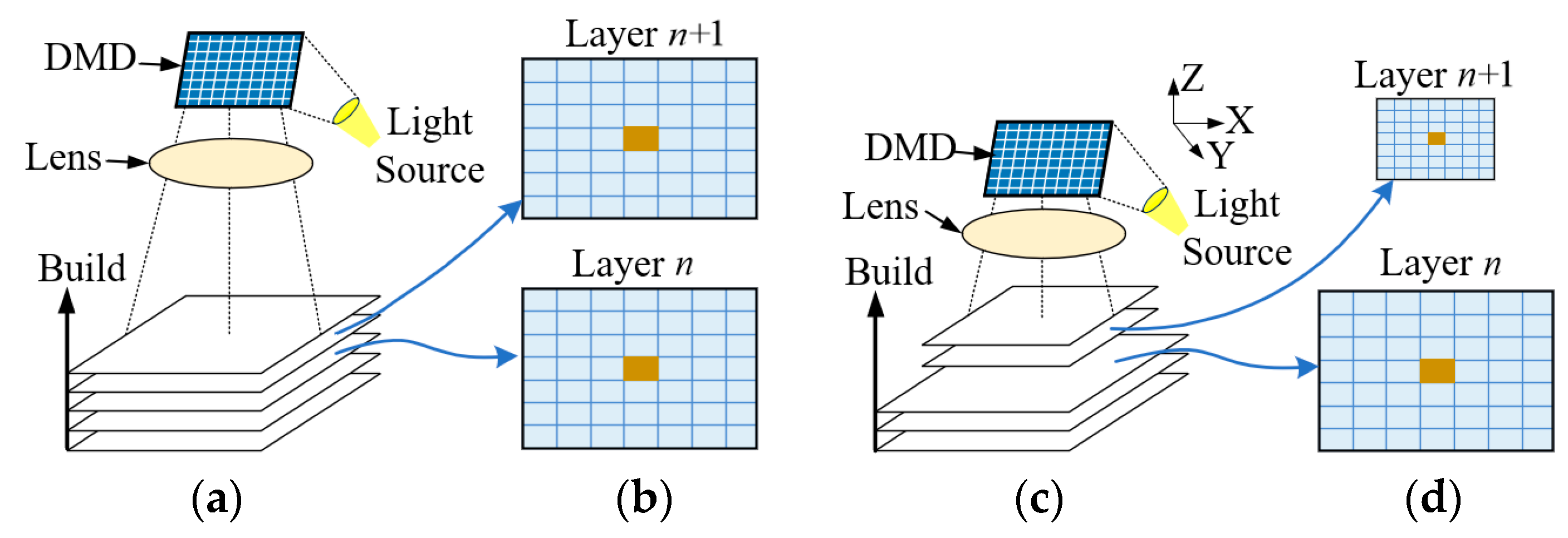
For the optical projection devices, the size and resolution of the projection images vary with the projected distance from the projection lens to the printed area. When the projection distance is fixed, the optimal projection size and resolution are also fixed. The common DLP photocuring 3D printing process adopts the cumulative curing molding with the fixed projection resolution. The simplified molding process is shown in Figure 1a,b. The projection distance from DMD to the molding liquid level is fixed, and the resolution of each mask pattern projected to the molding liquid level is the same. Assuming that the dimension of either direction of the projection planes X and Y is 500 mm and there are 1000 pixels along this direction, the dimension of each pixel is 500 μm, which means that the minimum feature size is 500 μm. To print features as small as possible basis on a certain molding size, the molding method with the adjustable resolution in the printing process is designed in this study. The forming process adopted is shown in Figure 1c,d. After printing the th layer of large format molding, the nth layer need to improve the fabrication resolution. More specifically, the lens position of the projection device is adjusted and the projection device is moved in space to project the best projection resolution to the forming liquid surface. The optics are modified to focus the light into a smaller image to fabricate features smaller than 500 μm.
We used a low-cost consumer-level projector ASK M5(ASK, Fredrikstad, Norway), and the optical lens is placed in front of the projector to shorten the projection distance and ensure sufficient light intensity to solidify the polymer. With the lens is installed, the optimal projection plane is 92 mm × 69 mm before manual zoom, while the size of after zoom is 74 mm × 56 mm. Affected by the uneven light intensity and the distortion of the edge of the projection frame, the effective molding frames are 70 mm × 56 mm and 55 mm × 44 mm, which are called large format and small format, respectively, in the experiment.
2.2. Design of 3D Printing Scheme
The commonly technology using DLP 3D printing can be divided into top-down projection stereolithography and bottom-up projection stereolithography according to the projection position.
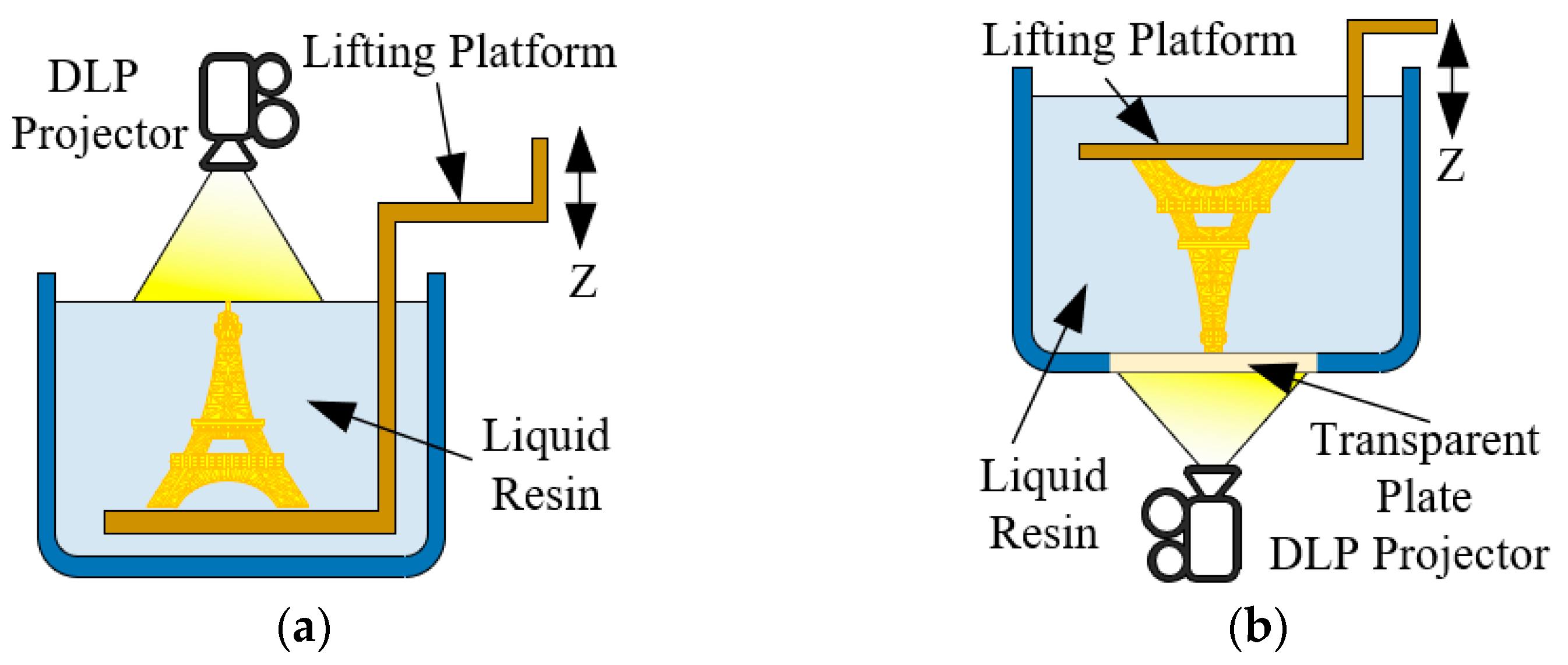
As shown in Figure 2b, the object is solidified at the bottom of the resin tray with a transparent window in the bottom-up projection system, which can well control the thickness and printing precision. However, the printed parts are affected by the separation force during the pull-up process, and the additional disengagement materials are needed to refill. The top-down projection stereolithography (Figure 2a) adopts mask pattern projected to the free liquid surface to cure objects, and the structure is relatively simple and flexible, avoiding separation force. Therefore, the top-down projection molding method is used for the design of 3D printer in the study. The overall design scheme is shown in Figure 3.
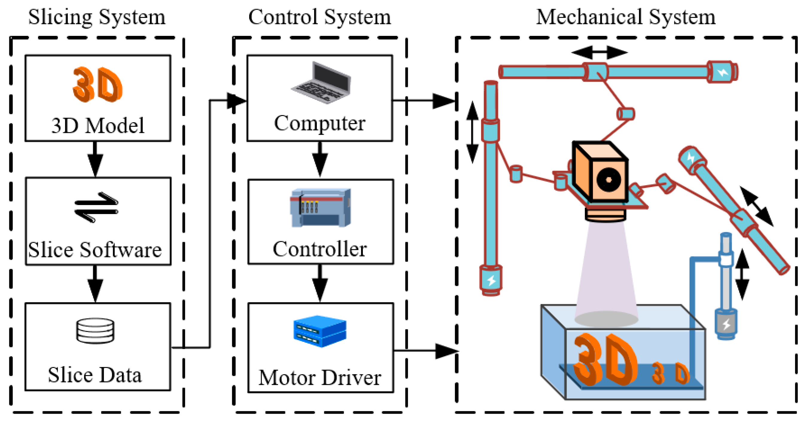
The whole printing scheme is mainly composed of slicing system, control system and mechanical system. In the slicing system, the preprocessing software is used to slice and generate the 3D model slice data in cli. format. And the computer in the control system processes the slice data, controls the projector to irradiate the mask, and communicates with the controller to realize the orderly movement of the four-axis motor in the mechanical system. The parallel mechanism in the mechanical system drives the projection to move in the effective workspace. The position of the projection lens is changed, and the best projection surfaces at different positions are projected onto the raised forming platform to print the object.
3. Experimental Device
3.1. Mechanical Structure
The overall mechanical structure model is shown in Figure 4.
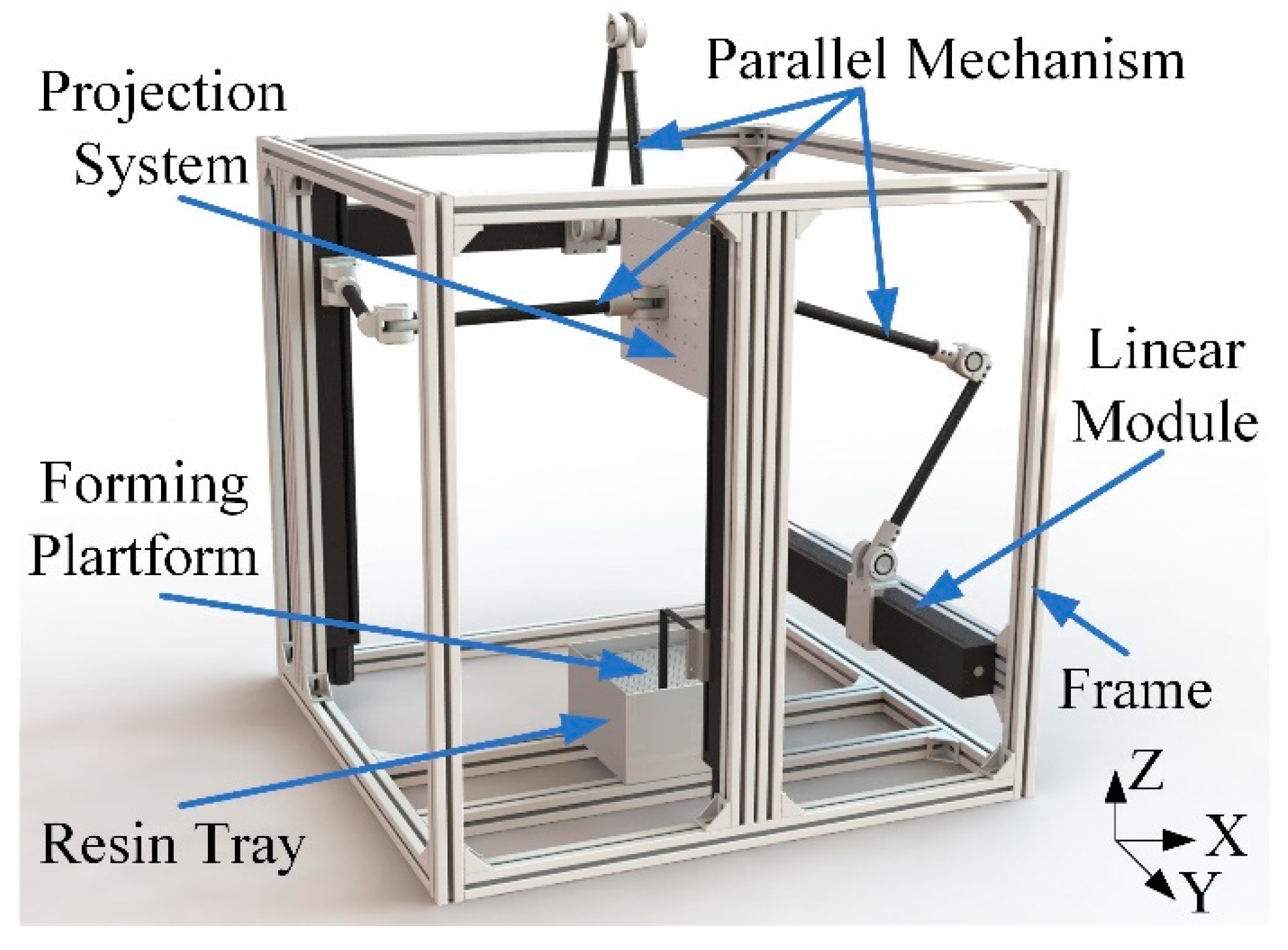
The structure of 3D printing prototype is mainly composed of the frame, the projection system, the tripteron parallel mechanism, the forming platform, and the resin tray.
3.1.1. Kinematic Analysis of Tripteron Parallel Mechanism
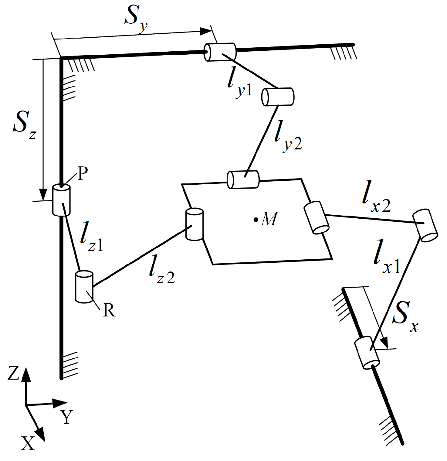
The motion diagram of the Tripteron parallel mechanism is shown in Figure 5. The mechanism consists of two platforms (static platform and moving platform) and three branch chains. The static platform is the fixed frame. The moving platform is connected to the fixed support by three branch chains, each of which is composed of a moving pair (P) and three rotating pairs (R). The P and R axes on a single branch chain are parallel to each other, and the P axes between branches are orthogonal and parallel to the X, Y and Z axis respectively. Under the joint action of the three branch chains, the pure movement of the moving platform in the X, Y and Z directions is realized. Point M is the center point of the moving platform. , and are the motion distances of the slider relative to the origin of global coordinates, respectively. , and represent the length of two rods in the three branch chains, respectively.
Since point M is the intersection of three mutually orthogonal branch chain planes, the displacement of point M in the X, Y and Z directions is synchronized with the sliding block displacement S of the three branch chains. Therefore, the position solution of the mechanism is obtained from the following expression of Equation (1):
where M is and S is . Then, by differentiating Equation (1), the velocity relation between the moving platform and the slider can be obtained following the expression of Equation (2):
where is , is and J is a Jacobian 3 × 3 identity matrix. It can be seen from the above analysis that the movements of the slider and the moving platform in the X, Y and Z directions are one-to-one corresponding.
M = S
3.1.2. Design of Tripteron Parallel Mechanism
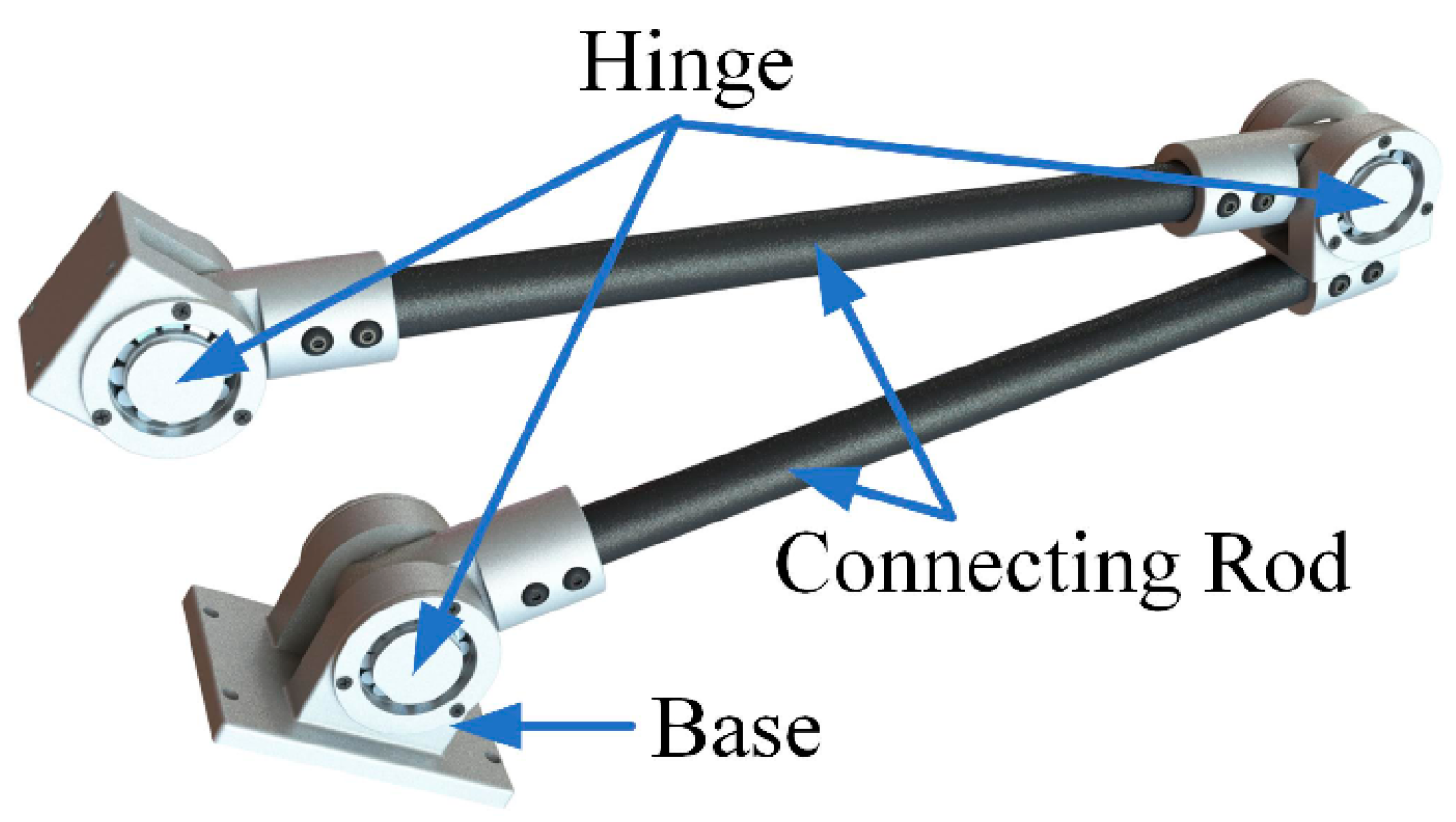
After analysis, it can be known that the tripteron parallel mechanism is a fully decoupled 3-DoF translational parallel mechanism [37]. The projection device is fixedly connected with the moving platform and one branch chain of mechanism is shown in Figure 6. So, it is ensured that the projection is located at the intersection of the three orthogonal branch planes. The base at one end of each branch chain is fixedly connected with the slide block on the linear module and driven by the servo motor. The other end is connected to the projection device by the hinge joint. Finally, the projection device can achieve 3-DoF translational motion in space. It is not difficult to conclude that the size of the mechanism workspace depends on the length of the branch linkage. Theoretically, when the connecting rod length is enough, the workspace can envelop any geometry within the fixed frame. Considering the overall structure size, the appropriate rod length is 360 mm after theoretical analysis and modeling simulation. Its workspace is greater than 300 mm × 300 mm × 300 mm, which fully meets the design requirements.
3.1.3. Structural Components
The fixed frame adopts aluminum profile with the overall size of 1000 mm × 1000 mm × 1000 mm. The linear module is fixed on the groove of the aluminum profile, and the limit sensor is installed for the accurate positioning of the motor. In the early experimental stage, in order to avoid resin waste, the design size of the resin tray is 120 mm × 70 mm × 50 mm, which can be flexibly installed at the fixed frame. The forming platform adopts the aluminum plate with dense holes, which is connected with the linear module drive block through the punching parts. The optical projection can be leveled by the projection system. The resolution of the final printed objects is based on the resolution of the DMD chip, as well as the wavelength and power of the light source of optical projection equipment. However, the special optical machine in the DLP 3D printing is expensive. In order to develop a low-cost machine [38], a consumer-level DLP projector with Ultra High Performance (UHP) as the light source is used. In addition, to reduce the motion error, the servo motor and the KM46 linear module with a positioning accuracy of 0.025 mm, and the repeated positioning accuracy of ± 0.003 mm are adopted.
3.2. Control System
3.2.1. Design of Motion Control System
The decoupling characteristics of the tripteron parallel mechanism provide the convenience for the motion control system. The projection position can be accurately controlled only by considering the positions of driving sliders on X, Y and Z axes. The controller PLC S7-1215 (Siemens, Berlin, Germany), three servo motors and drivers, the limit sensors, the displacement sensor, the low-voltage apparatus, etc. are the primary components of the motion control system. For the convenience of debugging the program in the experimental stage, the KTP700 touch screen motion control interface is compiled, which can quickly achieve the functions of the motor inching control, the position control, the speed control, the projection position recording, and the automatic operation.
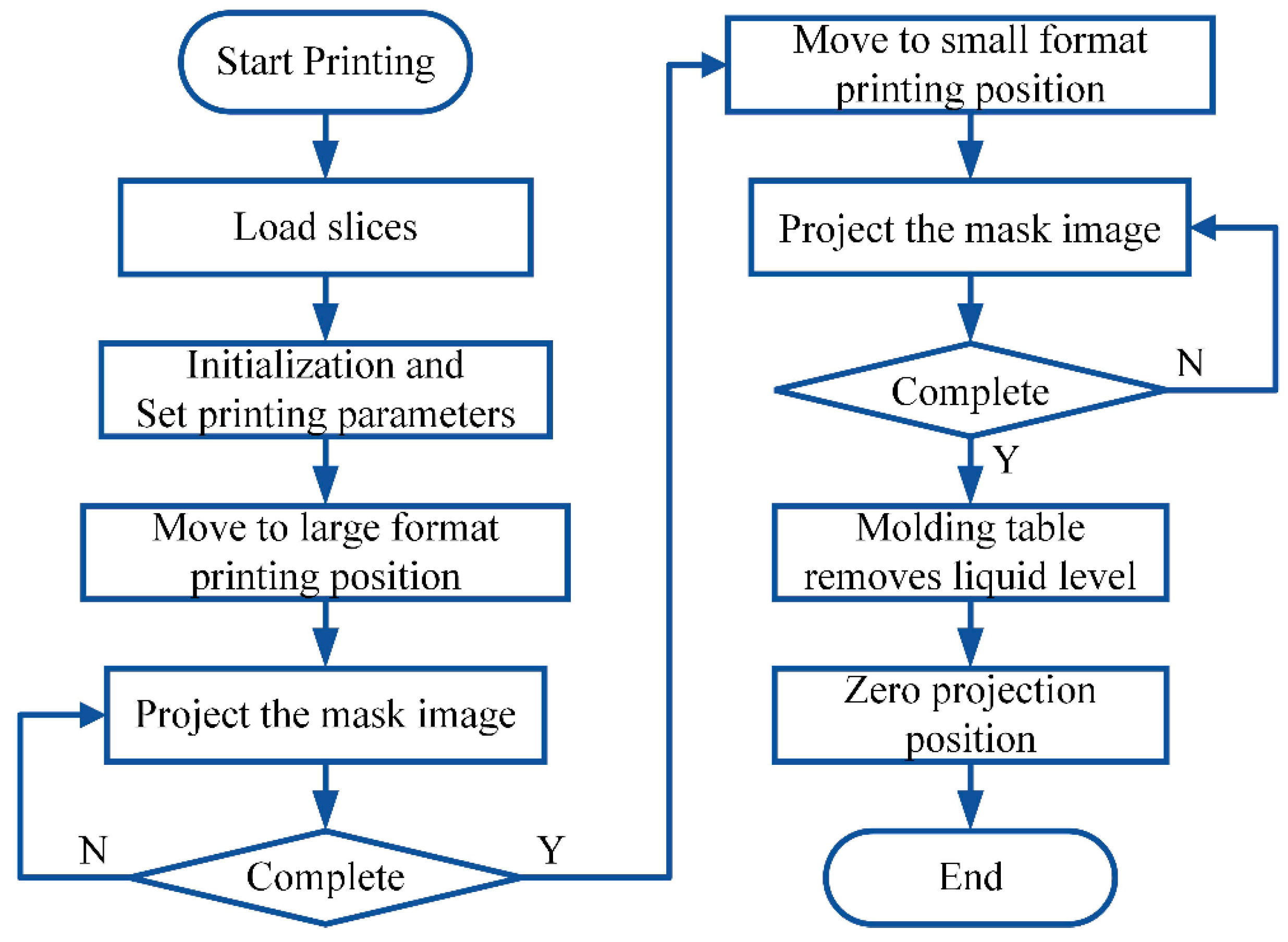
3.2.2. The Printing Control Process
The print control flow chart is shown in Figure 7. After the 3D model of the printed object is sliced (Magics24.0, Materialise, Leuven, Belgium) and generated as layer image data, it is read by the PC. The projector and PC are connected through VGA to transmit image data. After initializing and setting various printing parameters, the machine completes the printing according to the requirements.
3.3. Build Prototype
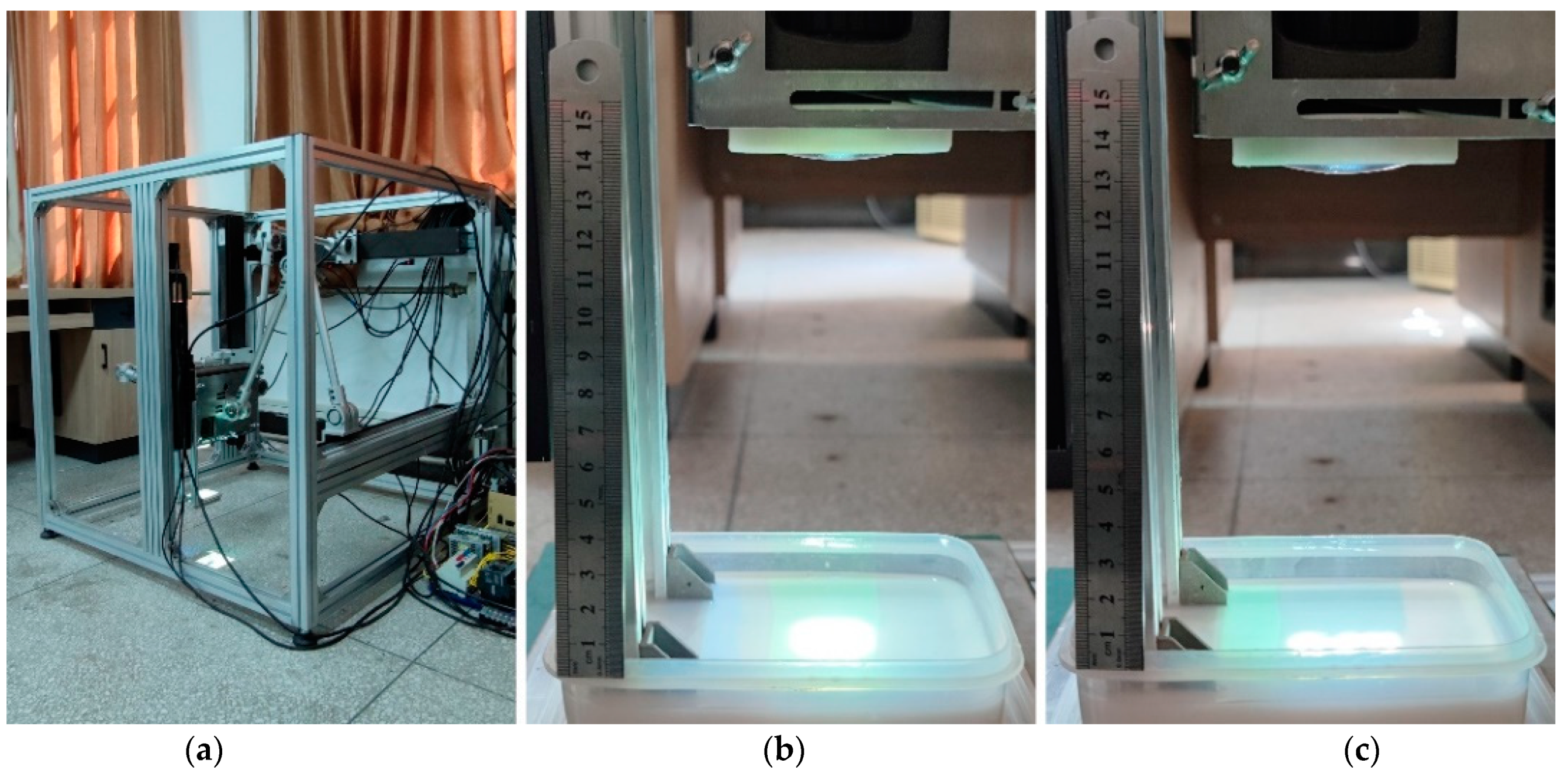
After completing the above work, the non-standard parts are manufactured. The level is used for the calibration in the process of mechanical assembly, and the physical prototype is set up, as shown in Figure 8a. Photographs of the different manufacturing stages on the built DLP 3D printing prototype are shown in Figure 8b,c.
4. Experiments and Discussion
4.1. Experimental Material
Resin materials used for photocuring can be divided into ultraviolet (UV) light and visible light resins according to the sensitive wavelength of the photoinitiator. Articles [24,25] report research contributions to visible light materials, which provide important references for scholars. In this paper, we selected a commercially available liquid resin that absorbs at a wavelength of 405 nm, which can be emitted by a UHP. The main parameters of the liquid resin are shown in Table 1, and the experiment was carried out at room temperature.
4.2. Parameters Optimization Based on the Orthogonal Method
For the top-down projection molding method, the processing parameters affecting the fabrication resolution include the exposure time and the waiting leveling time, and the thickness of the bottom layer and every single layer. The bottom layer curing is mainly used to cover the drainage holes on the molding platform and support the printing model. In the experiment, it is found that the lack of exposure of the bottom layer will lead to the faults, the holes and other phenomena. However, the overexposure curing of the bottom layer will increase the difficulty of the separation between the bottom layer and the molding platform. Combined with the designed molding platform, under the large format before zoom and small format after zoom, the appropriate exposure time of the bottom layer is respectively 60 s and 50 s with 0.1 mm bottom layer.
On this basis, it is found that the monolayer thickness, the monolayer exposure time and the waiting leveling time have the greatest influence on the model forming quality. So it is necessary to optimize its parameters. The orthogonal method can obtain the accurate test results by scientifically selecting some representative points and using fewer test times. It is widely used to study multi-factor levels for its high efficiency, the fast speed and so on. In this experiment, there are three factors, which are the monolayer thickness (A), the monolayer exposure time (B) and the waiting leveling time (C). The values of each factor level under the small scale selected by the preliminary experiment are shown in Table 2.
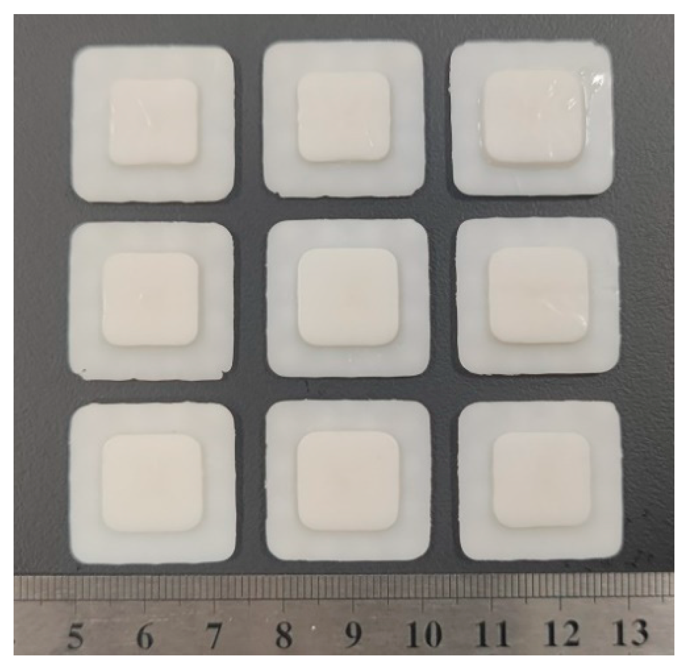
Nine group tests were completed on the prototype using the L9 () orthogonal test table. The cross-section size of the test sample is 14 mm × 13.7 mm (rounded rectangle), and the printing height is 2.4 mm. The printed sample is solidified with the bottom layer to eliminate errors caused by the thickness of the bottom layer. Using a vernier caliper (GENERTEC HARBIN MEASURING & CUTTING TOOL CO., LTD, Harbin, China) to measure the test sample X, Y and Z directions. Each sample is measured 6 times to obtain the average value, and the Relative Size Error (RSE) is used to represent the dimensional accuracy of the printed sample.
RSE = |Measured value − Theoretical value| / Theoretical value × 100%.
The RSE of each direction is represented by ∆X, ∆Y and ∆Z respectively. The printed samples are shown in Figure 9.
The measured results are shown in Table 3. It can be seen that the RSE is 1.02~3.02%, 1.12~3.28%, 1.11~3.89% in X, Y and Z direction, separately. So the Z direction with large RSE is selected as the reference standard of the dimension accuracy. The range analysis of the RSE is shown in Table 4.
The greater the range R, the greater the effect on optimization. From the range results, it can be concluded that the primary and secondary order of the influencing factors is A > C > B. That is, the influence factors is the monolayer thickness, the waiting leveling time and the monolayer exposure time in turn. From the perspective of the optimization effect, the RSE should be as small as possible. So the factor level combination with the best dimensional accuracy is . Therefore, the optimal processing parameters are that monolayer thickness is 0.08 mm, monolayer exposure time is 20 s, and waiting leveling time is 6 s. Using the same method, the optimal process parameters under large format surface can be obtained as 0.08 mm, 30 s and 6 s.
4.3. Minimum Feature Test
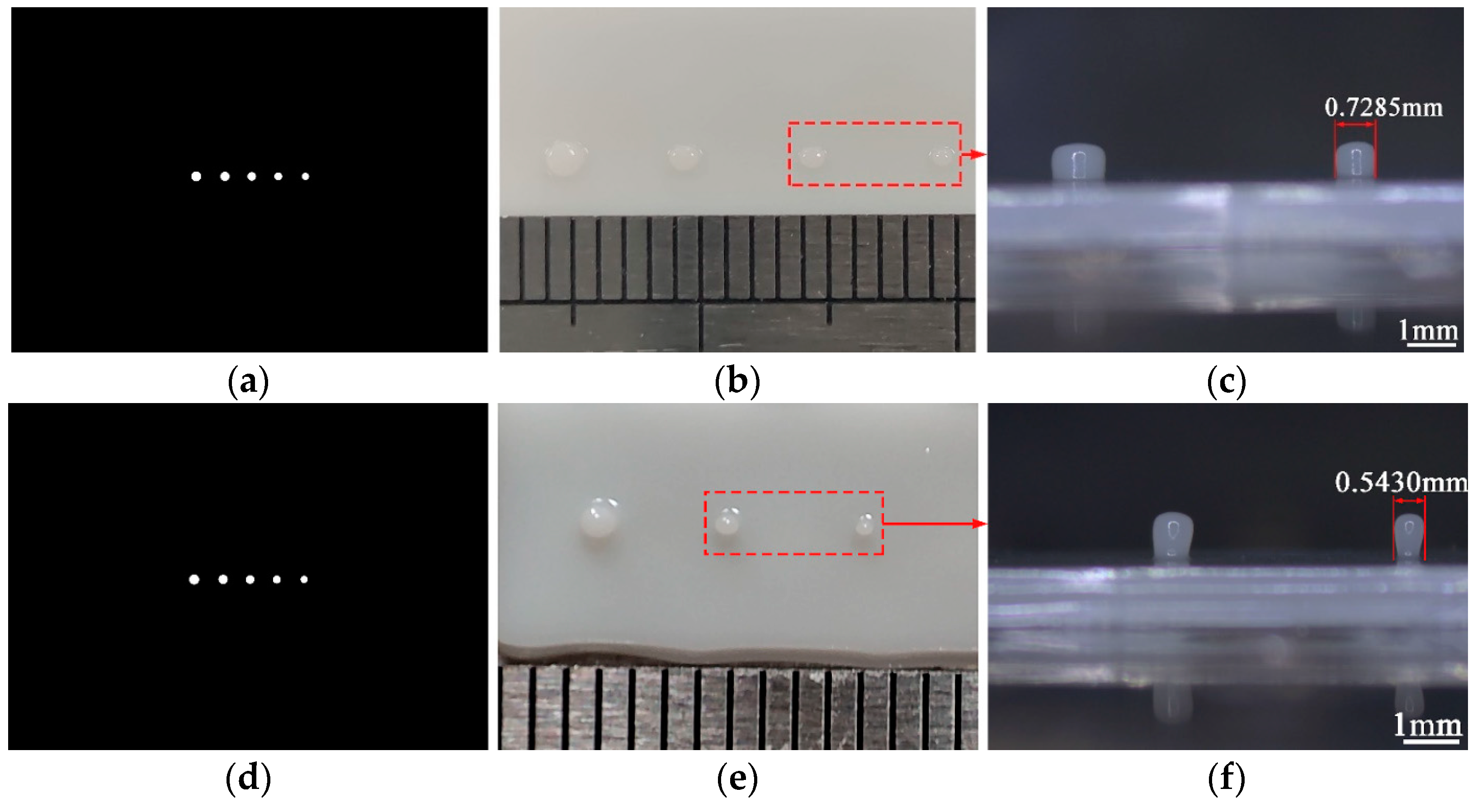
In order to evaluate the minimum manufacturing resolution and facilitate measurement data, we designed Figure 10a,d as the projection mask images in the large format and small format. The mask image is a set of progressively smaller dots that differ from each other by two pixels. After printing, the minimum feature resolution of the prototype is evaluated using the cylindrical diameter formed by the dot accumulation on the part. Using an industrial microscope BC4800 (Bocheng Electronics, Dongguan, China) to photograph fine features on the test samples, the results are shown in Figure 10b,c,e,f.
As can be seen from the Figure 10c,f the minimum features show the shape of the round table, and this phenomenon gradually disappears with the size increases. The molding process shows that the smoothness of the free liquid surface is affected by the viscosity, the layer thickness, the solidified area of the bottom and other factors. When the solidified area of the bottom is large and the layer thickness is small, the liquid surface will show the characteristics of high center and low edge. In addition, the spot energy during curing presents a Gaussian distribution, that is, the energy gradually decays from the center to the surrounding. Therefore, although we choose the low viscosity liquid resin, it is easy to cause uneven layer thickness at the curing point when printing features on the basis of the bottom curing. As the number of printing layers increases, the levelness of the liquid surface and the curing effect are improved. Correspondingly, when the size of the feature increases gradually, this phenomenon will gradually improve. For a more accurate evaluation, the boundary of the feature was selected to measure the size. The minimum feature size that can be formed in large and small format is 0.7285 mm and 0.5430 mm, respectively. From the data it can conclude that the prototype has the capacity to form 0.73 mm and 0.55 mm feature resolution in two formats. The manufacturing capacity depends mainly on the DLP optical machine used. The low-cost consumer-level projector used in the experiment has a performance gap compared to the commercial one. But the current study focuses on the change in size, not size. Therefore, this scale of manufacture is acceptable.
4.4. Small Feature Forming Contrast Experiment
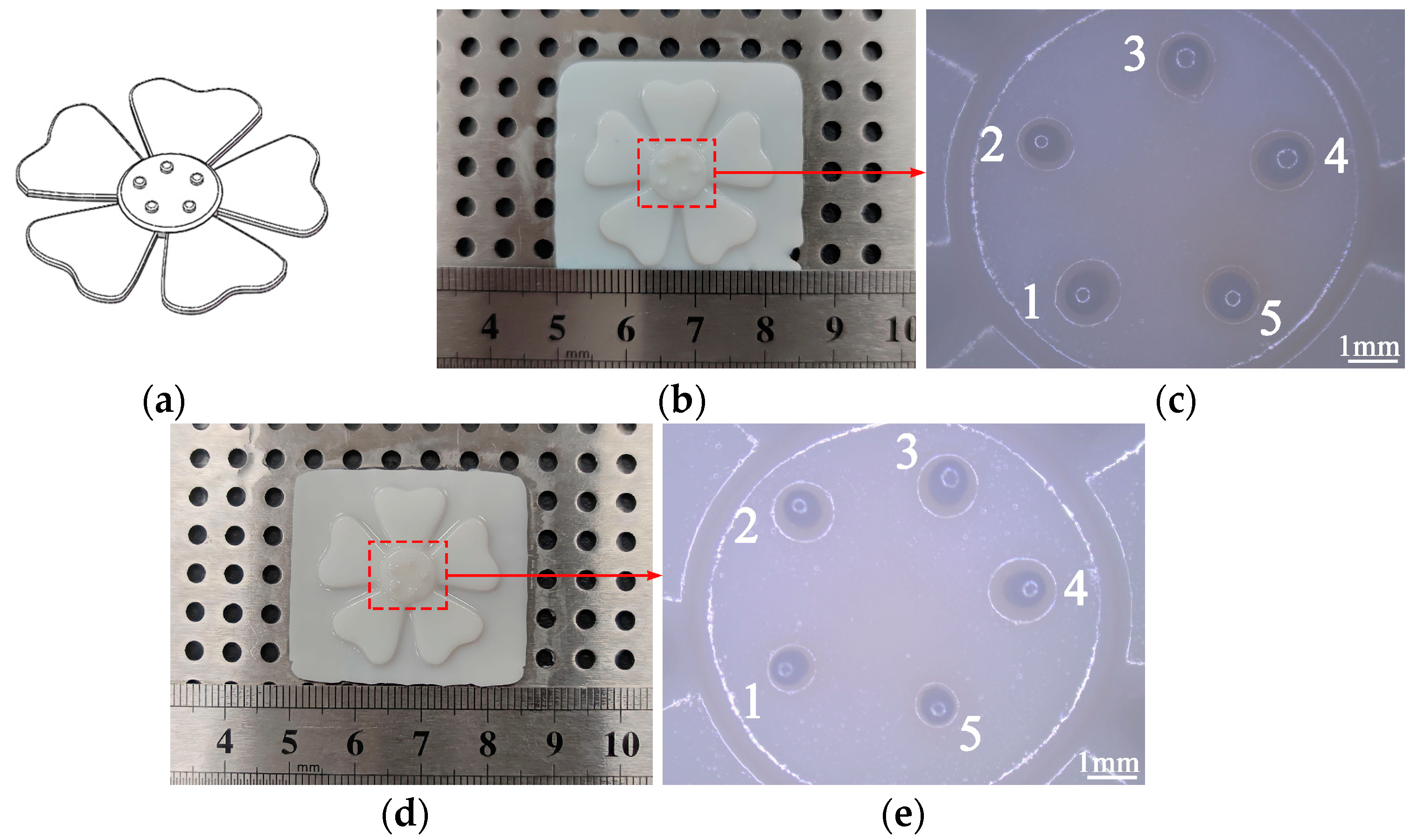
In order to test the feasibility of this printing scheme, we designed and printed the flowers with small cylindrical features called stamens. It can clearly illustrates our verification method. The model is shown in Figure 11a, and the printed models are shown in Figure 11b,d. The original dimensions of both models are the same, the difference is in how the features are molded. Specifically, Figure 11b adopts the common molding method, that is, parts and features are printed with fixed projection distance and fixed projection resolution. Figure 11d adopts the molding scheme proposed in the paper, that is, when printing features, the projection distance is shortened and a small format is used for printing. The original size of small features is designed to be 0.85 mm.
Using an industrial microscope BC4800 (Bocheng Electronics, Dongguan, China) to photograph features and the results are shown in Figure 11c,e. The maximum diameter of the cylindrical feature was obtained using the measurement function in the microscope, and the results are shown in Table 5. We characterize the change in molding resolution by comparing the feature size under the two methods. The sizes of features 1–5 at a fixed resolution are 0.8689 mm, 0.8477 mm, 0.8543 mm, 0.8792 mm and 0.8278 mm, respectively, where the RSE ranges from 0.51% to 3.41%. The sizes of features 1–5 using a small format molding are 0.6689 mm, 0.649 mm, 0.6495 mm, 0.6814 mm, and 0.6358 mm, respectively, and the respective sizes are reduced by about 1.3, 1.31, 1.31, 1.29, and 1.3 times. Overall, the size of the features printed in both ways is proportionally reduced. And the average size is 0.8556 mm and 0.6569 mm, which is about 1.3 times smaller. In addition, the features size printed in the small format are lower than 0.7 mm, which is not within the large format forming capability. Therefore, the features’ resolution is improved by about 1.3 times.
It can also be seen from Figure 11c,e that the position of the features modeled with adjusted resolution changes slightly compared to the features modeled with fixed resolution. The reason is believed to be that in the process of adjusting the resolution, due to the assembly and motion errors of the prototype, the position of the adjusted dynamic mask projected on the liquid surface is slightly misaligned. In addition, it is also an important research content to conduct analysis experiments on the strength and other mechanical properties of the parts. Articles [39,40] provide valuable references for mechanical property analysis and experimental methods. However, in the current experiment, the proposed method is mainly verified from the perspective of size, and the analysis of mechanical properties such as the strength of the printed parts needs further research, which will be reported in future work.
5. Conclusions
In this work, to solve the problem of fabrication size and resolution of 3D printing based on DLP technology, an adjustment resolution approach based on parallel mechanism was proposed. And the prototype was built for experimental verification. The conclusions are as follows:
- Based on the projection stereolithography method, a DLP 3D printing prototype with parallel mechanism was established, which is different from the previous molding schemes with fixed molding resolution. It can adjust the resolution during the printing process to reduce the printing size of features.
- Compared with previous single-axis or X-Y motion platform structures, the use of tripteron 3-DoF parallel mechanism improves the motion flexibility. After analyzing its kinematics, a control program was developed according to the forming process. With the low-cost optical projection equipment moving in space using parallel structure, the projection resolution was changed in order to adapt to smaller size printing.
- The optimal molding processing parameters were obtained based on the orthogonal method. The forming contrast experiment was carried out on the prototype, and the results show that the fabrication resolution of features can be improved by about 1.3 times. The effectiveness of the approach was verified by experiments.
Author Contributions
Conceptualization, J.H. and J.X.; methodology, J.H. and B.Z.; software, B.Z.; validation, J.H. and B.Z.; formal analysis, J.H. and B.Z.; investigation, J.H. and B.Z.; resources, J.H.; data curation, B.Z. and Q.Z.; writing—original draft preparation, B.Z.; writing—review and editing, J.H., B.Z. and J.X.; visualization, J.H., B.Z. and Q.Z.; supervision, J.H.; project administration, J.H.; funding acquisition, J.H. All authors have read and agreed to the published version of the manuscript.
Funding
This research was funded by Henan Province Scientific and Technological Research Plan (Grant Nos. 222102220008, 212102210045), Fundamental Research Funds for the Universities of Henan Province (Grant No. NSFRF210339) and Key Discipline of Mechanical Engineering in Henan Polytechnic University and the University Doctoral Fund (Grant No. B2016-24).
Institutional Review Board Statement
Not applicable.
Informed Consent Statement
Not applicable.
Data Availability Statement
Not applicable.
Conflicts of Interest
The authors declare no conflict of interest.
References
- Mehrpouya, M.; Dehghanghadikolaei, A.; Fotovvati, B.; Vosooghnia, A.; Emamian, S.S.; Gisario, A. The Potential of Additive Manufacturing in the Smart Factory Industrial 4.0: A Review. Appl. Sci. 2019, 9, 3865. [Google Scholar] [CrossRef] [Green Version]
- Saboori, A.; Gallo, D.; Biamino, S.; Fino, P.; Lombardi, M. An Overview of Additive Manufacturing of Titanium Components by Directed Energy Deposition: Microstructure and Mechanical Properties. Appl. Sci. 2017, 7, 883. [Google Scholar] [CrossRef] [Green Version]
- Wallin, T.J.; Pikul, J.; Shepherd, R.F. 3D printing of soft robotic systems. Nat. Rev. Mater. 2018, 3, 84–100. [Google Scholar] [CrossRef]
- Nazir, A.; Jeng, J.-Y. A high-speed additive manufacturing approach for achieving high printing speed and accuracy. Proc. IMechE Part C J. Machanical Eng. Sci. 2020, 234, 2741–2749. [Google Scholar] [CrossRef]
- De Beer, M.P.; van der Laan, H.L.; Cole, M.A.; Whelan, R.J.; Burns, M.A.; Scott, T.F. Rapid, continuous additive manufacturing by volumetric polymerization inhibition patterning. Sci. Adv. 2019, 5, eaau8723. [Google Scholar] [CrossRef] [PubMed] [Green Version]
- Hwa, L.C.; Rajoo, S.; Noor, A.M.; Ahmad, N.; Uday, M.B. Recent advances in 3D printing of porous ceramics: A review. Curr. Opin. Solid State Mater. Sci. 2017, 21, 323–347. [Google Scholar] [CrossRef]
- Saini, J.S.; Dowling, L.; Kennedy, J.; Trimble, D. Investigations of the mechanical properties on different print orientations in SLA 3D printed resin. Proc. IMechE Part C J. Machanical Eng. Sci. 2020, 234, 2279–2293. [Google Scholar] [CrossRef]
- Wickramasinghe, S.; Do, T.; Tran, P. FDM-Based 3D Printing of Polymer and Associated Composite: A Review on Mechanical Properties, Defects and Treatments. Polymers 2020, 12, 1529. [Google Scholar] [CrossRef]
- Melchels, F.P.W.; Feijen, J.; Grijpma, D.W. A review on stereolithography and its applications in biomedical engineering. Biomaterials 2010, 31, 6121–6130. [Google Scholar] [CrossRef] [Green Version]
- Huang, J.; Qin, Q.; Wang, J. A Review of Stereolithography: Processes and Systems. Processes 2020, 8, 1138. [Google Scholar] [CrossRef]
- Mohamed, O.A.; Masood, S.H.; Bhowmik, J.L. Optimization of fused deposition modeling process parameters: A review of current research and future prospects. Adv. Manuf. 2015, 3, 42–53. [Google Scholar] [CrossRef]
- Solomon, I.J.; Sevvel, P.; Gunasekaran, J. A review on the various processing parameters in FDM. Mater. Today Proc. 2021, 37, 509–514. [Google Scholar] [CrossRef]
- Olakanmi, E.O.; Cochrane, R.F.; Dalgarno, K.W. A review on selective laser sintering/melting (SLS/SLM) of aluminium alloy powders: Processing, microstructure, and properties. Prog. Mater. Sci. 2015, 74, 401–477. [Google Scholar] [CrossRef]
- Aimar, A.; Palermo, A.; Innocenti, B. The Role of 3D Printing in Medical Applications: A State of the Art. J. Healthc. Eng. 2019, 2019, 5340616. [Google Scholar] [CrossRef] [Green Version]
- Vaz, V.M.; Kumar, L. 3D Printing as a Promising Tool in Personalized Medicine. AAPS PharmSciTech 2021, 22, 49. [Google Scholar] [CrossRef]
- Pagac, M.; Hajnys, J.; Ma, Q.-P.; Jancar, L.; Jansa, J.; Stefek, P.; Mesicek, J. A Review of Vat Photopolymerization Technology: Materials, Applications, Challenges, and Future Trends of 3D Printing. Polymers 2021, 13, 598. [Google Scholar] [CrossRef]
- Joshi, S.C.; Sheikh, A.A. 3D printing in aerospace and its long-term sustainability. Virtual Phys. Prototyp. 2015, 10, 175–185. [Google Scholar] [CrossRef]
- Böckin, D.; Tillman, A.-M. Environmental assessment of additive manufacturing in the automotive industry. J. Clean. Prod. 2019, 226, 977–987. [Google Scholar] [CrossRef]
- Tay, Y.W.D.; Panda, B.; Paul, S.C.; Noor Mohamed, N.A.; Tan, M.J.; Leong, K.F. 3D printing trends in building and construction industry: A review. Virtual Phys. Prototyp. 2017, 12, 261–276. [Google Scholar] [CrossRef]
- Shahrubudin, N.; Lee, T.C.; Ramlan, R. An Overview on 3D Printing Technology: Technological, Materials, and Applications. Procedia Manuf. 2019, 35, 1286–1296. [Google Scholar] [CrossRef]
- Ngo, T.D.; Kashani, A.; Imbalzano, G.; Nguyen, K.T.Q.; Hui, D. Additive manufacturing (3D printing): A review of materials, methods, applications and challenges. Compos. Part B-Eng. 2018, 143, 172–196. [Google Scholar] [CrossRef]
- Bagheri, A.; Jin, J. Photopolymerization in 3D Printing. ACS Appl. Polym. Mater. 2019, 1, 593–611. [Google Scholar] [CrossRef] [Green Version]
- Quan, H.; Zhang, T.; Xu, H.; Luo, S.; Nie, J.; Zhu, X. Photo-curing 3D printing technique and its challenges. Bioact. Mater. 2020, 5, 110–115. [Google Scholar] [CrossRef] [PubMed]
- Wang, G.; Hill, N.S.; Zhu, D.; Xiao, P.; Coote, M.L.; Stenzel, M.H. Efficient Photoinitiating System Based on Diaminoanthraquinone for 3D Printing of Polymer/Carbon Nanotube Nanocomposites under Visible Light. ACS Appl. Polym. Mater. 2019, 1, 1129–1135. [Google Scholar] [CrossRef]
- Zhu, Y.; Ramadani, E.; Egap, E. Thiol ligand capped quantum dot as an efficient and oxygen tolerance photoinitiator for aqueous phase radical polymerization and 3D printing under visible light. Polym. Chem. 2021, 12, 5106–5116. [Google Scholar] [CrossRef]
- Sun, C.; Fang, N.; Wu, D.M.; Zhang, X. Projection micro-stereolithography using digital micro-mirror dynamic mask. Sens. Actuators A-Phys. 2005, 121, 113–120. [Google Scholar] [CrossRef]
- Mao, M.; He, J.; Li, X.; Zhang, B.; Lei, Q.; Liu, Y.; Li, D. The Emerging Frontiers and Applications of High-Resolution 3D Printing. Micromachines 2017, 8, 113. [Google Scholar] [CrossRef] [Green Version]
- Maines, E.M.; Porwal, M.K.; Ellison, C.J.; Reineke, T.M. Sustainable advances in SLA/DLP 3D printing materials and processes. Green Chem. 2021, 23, 6863–6897. [Google Scholar] [CrossRef]
- Wu, L.; Zhao, L.; Jian, M.; Mao, Y.; Yu, M.; Guo, X. EHMP-DLP: Multi-projector DLP with energy homogenization for large-size 3D printing. Rapid Prototyp. J. 2018, 24, 1500–1510. [Google Scholar] [CrossRef]
- Waldbaur, A.; Carneiro, B.; Hettich, P.; Wilhelm, E.; Rapp, B.E. Computer-aided microfluidics (CAMF): From digital 3D-CAD models to physical structures within a day. Microfluid. Nanofluid. 2013, 15, 625–635. [Google Scholar] [CrossRef]
- Yi, R.; Wu, C.; Liu, Y.-J.; He, Y.; Wang, C.C.L. Delta DLP 3-D Printing of Large Models. IEEE Trans. Autom. Sci. Eng. 2018, 15, 1193–1204. [Google Scholar] [CrossRef] [Green Version]
- Wu, C.; Yi, R.; Liu, Y.J.; He, Y.; Wang, C.C.L. Delta DLP 3D printing with large size. In Proceedings of the 2016 IEEE/RSJ International Conference on Intelligent Robots and Systems (IROS), Daejeon, Republic of Korea, 9–14 October 2016. [Google Scholar] [CrossRef]
- Emami, M.M.; Barazandeh, F.; Yaghmaie, F. Scanning-projection based stereolithography: Method and structure. Sens. Actuators A-Phys. 2014, 218, 116–124. [Google Scholar] [CrossRef]
- Wang, Y.; Chen, R.; Liu, Y. A double mask projection exposure method for stereolithography. Sens. Actuators A 2020, 314, 112228. [Google Scholar] [CrossRef]
- Zhou, C.; Ye, H.; Zhang, F. A Novel Low-Cost Stereolithography Process Based on Vector Scanning and Mask Projection for High-Accuracy, High-Speed, High-Throughput and Large-Area Fabrication. In Proceedings of the ASME 2014 International Design Engineering Technical Conferences and Computers and Information in Engineering Conference, Buffalo, NY, USA, 17–20 August 2014. [Google Scholar] [CrossRef]
- Busetti, B.; Steyrer, B.; Lutzer, B.; Reiter, R.; Stampfl, J. A hybrid exposure concept for lithography-based additive manufacturing. Addit. Manuf. 2018, 21, 413–421. [Google Scholar] [CrossRef]
- Yen, P.-L.; Lai, C.-C. Dynamic modeling and control of a 3-DOF Cartesian parallel manipulator. Mechatronics 2009, 19, 390–398. [Google Scholar] [CrossRef]
- Varghese, G.; Moral, M.; Castro-Garcia, M.; Jose Lopez-Lopez, J.; Ramon Marin-Rueda, J.; Yague-Alcaraz, V.; Hernandez-Afonso, L.; Carlos Ruiz-Morales, J.; Canales-Vazquez, J. Fabrication and characterisation of ceramics via low-cost DLP 3D printing. Bol. Soc. Esp. Ceram. Vidr. 2018, 57, 9–18. [Google Scholar] [CrossRef]
- Aydin, L.; Kucuk, S. A method for more accurate FEA results on a medical device developed by 3D technologies. Polym. Adv. Technol. 2018, 29, 2281–2286. [Google Scholar] [CrossRef]
- Peker, A.; Aydin, L.; Kucuk, S.; Ozkoc, G.; Cetinarslan, B.; Canturk, Z.; Selek, A. Additive manufacturing and biomechanical validation of a patient-specific diabetic insole. Polym. Adv. Technol. 2020, 31, 988–996. [Google Scholar] [CrossRef]
Figure 1.
A comparison of fixed resolution and adjustable resolution molding process: (a) Fixed resolution molding process; (b) Build area and pixel size of each layer with fixed resolution; (c) Adjustable resolution molding process; (d) Build area and pixel size of each layer with adjustable resolution.

Figure 2.
(a) The top-down projection stereolithography; (b) The bottom-up projection stereolithography.
Figure 2.
(a) The top-down projection stereolithography; (b) The bottom-up projection stereolithography.

Figure 3.
Overall design scheme.

Figure 4.
Overall mechanical structure model.

Figure 5.
The motion diagram of the tripteron parallel mechanism.

Figure 6.
Single branched chain structure.

Figure 7.
The flow chart of the printing process.

Figure 8.
(a) Physical prototype; (b) Photograph to illustrate the large format printing stage; (c) Photograph to illustrate the small format printing stage after reducing the projection distance.
Figure 8.
(a) Physical prototype; (b) Photograph to illustrate the large format printing stage; (c) Photograph to illustrate the small format printing stage after reducing the projection distance.

Figure 9.
Orthogonal test samples.

Figure 10.
Minimum feature tests: (a) Large format mask test pattern; (b) Features printing under large format; (c) Enlarged features under large format; (d) Small format mask test pattern; (e) Features printing under small format; (f) Enlarged features under small format.
Figure 10.
Minimum feature tests: (a) Large format mask test pattern; (b) Features printing under large format; (c) Enlarged features under large format; (d) Small format mask test pattern; (e) Features printing under small format; (f) Enlarged features under small format.

Figure 11.
Features comparison test: (a) Test model: flowers with cylindrical small features (b) Test model printed at fixed resolution; (c) Small features printed at a fixed resolution, photographed with an industrial microscope; (d) Test model printed at adjustable resolution; (e) Small features printed with increased resolution during printing, photographed with an industrial microscope.


Table 1.
Parameters of liquid resin.
| Supplier | Viscosity | Wavelength | Density | Color |
|---|---|---|---|---|
| CREALITY | 150–250 mPa.s 1 | For 405 nm | 1.05–1.15 g/cm3 | White |
1 A low viscosity resin was chosen to reduce its influence on the leveling process of the free surface.
Table 2.
Factors level information.
| Level | Factors | ||
|---|---|---|---|
| A (mm) | B (s) | C (s) | |
| 1 | 0.06 | 18 | 4 |
| 2 | 0.08 | 20 | 5 |
| 3 | 0.1 | 22 | 6 |
Table 3.
Orthogonal test results.
| Test | A (mm) | B (s) | C (s) | ∆X (%) | ∆Y (%) | ∆Z (%) |
|---|---|---|---|---|---|---|
| 1 | 0.06 | 18 | 4 | 2.02 | 2.12 | 3.89 |
| 2 | 0.06 | 20 | 5 | 2.43 | 2.58 | 3.06 |
| 3 | 0.06 | 22 | 6 | 3.02 | 3.28 | 2.36 |
| 4 | 0.08 | 18 | 6 | 1.12 | 1.27 | 1.25 |
| 5 | 0.08 | 20 | 4 | 1.02 | 1.12 | 1.11 |
| 6 | 0.08 | 22 | 5 | 2.36 | 2.43 | 1.67 |
| 7 | 0.1 | 18 | 5 | 2.57 | 2.63 | 1.81 |
| 8 | 0.1 | 20 | 6 | 1.74 | 1.73 | 2.08 |
| 9 | 0.1 | 22 | 4 | 1.95 | 2.17 | 2.64 |
Table 4.
Range analysis table of RSE in Z direction %.
| Data 1 | A | B | C |
|---|---|---|---|
| 3.10 | 2.31 | 2.55 | |
| 1.34 | 2.08 | 2.18 | |
| 2.18 | 2.22 | 1.90 | |
| R | 1.76 | 0.23 | 0.65 |
1 is the mean at level i.
Table 5.
Features size of model by two methods.
| Forming Method | Small Features Size (mm) | ||||
|---|---|---|---|---|---|
| 1 | 2 | 3 | 4 | 5 | |
| Fixed resolution | 0.8689 | 0.8477 | 0.8543 | 0.8792 | 0.8278 |
| Adjustable resolution | 0.6689 | 0.6490 | 0.6495 | 0.6814 | 0.6358 |
Publisher’s Note: MDPI stays neutral with regard to jurisdictional claims in published maps and institutional affiliations. |
© 2022 by the authors. Licensee MDPI, Basel, Switzerland. This article is an open access article distributed under the terms and conditions of the Creative Commons Attribution (CC BY) license (https://creativecommons.org/licenses/by/4.0/).
Share and Cite
MDPI and ACS Style
Huang, J.; Zhang, B.; Xiao, J.; Zhang, Q. An Approach to Improve the Resolution of DLP 3D Printing by Parallel Mechanism. Appl. Sci. 2022, 12, 12905. https://doi.org/10.3390/app122412905
AMA Style
Huang J, Zhang B, Xiao J, Zhang Q. An Approach to Improve the Resolution of DLP 3D Printing by Parallel Mechanism. Applied Sciences. 2022; 12(24):12905. https://doi.org/10.3390/app122412905
Chicago/Turabian StyleHuang, Junjie, Bowen Zhang, Junfeng Xiao, and Qinlei Zhang. 2022. "An Approach to Improve the Resolution of DLP 3D Printing by Parallel Mechanism" Applied Sciences 12, no. 24: 12905. https://doi.org/10.3390/app122412905
Note that from the first issue of 2016, this journal uses article numbers instead of page numbers. See further details here.