


Developments in 3D Visualisation of the Rail Tunnel Subsurface for Inspection and Monitoring

Abstract
:Featured Application
Abstract
1. Introduction
2. Materials and Methods
3. RTI Data Acquisition Methods
3.1. Visual Methods
3.2. Acoustic Methods
3.3. Laser Methods
3.4. Thermographic Methods
- Results are highly sensitive to ambient temperature conditions which diminishes anomaly contrast (e.g., daily and seasonal variation);
- Thermal insulation and heat-resistant coatings used for tunnel temperate regulation and fire resilience can skew results. High thermal dissipation can easily restrict penetration d < 30 mm [62];
- Subsurface water content variation (e.g., increased permeation following rainfall or snow) can mask or exaggerate thermal profiles of faults;
- Enclosed, curved tunnel geometry restricts available viewing angles and confine results to 2D, even in a 3D mesh overlay, making inference of feature depth and physical form very challenging even for experienced operatives.
3.5. Gravity Methods
3.6. Radar Methods
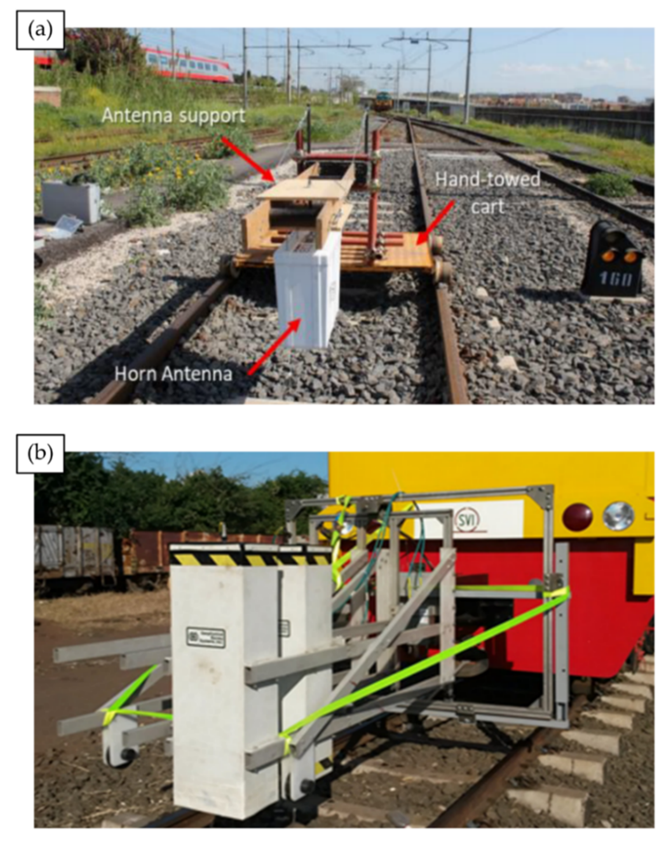
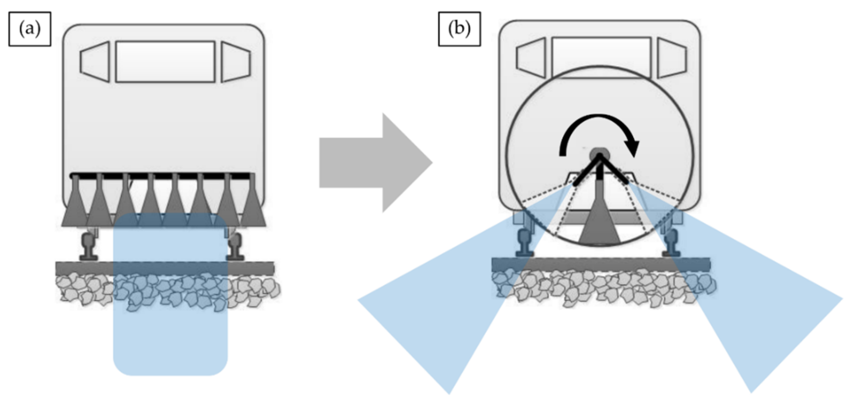
- Trolley-Mounted [75,76,77] (Figure 4a)—Units commonly feature interchangeable air-coupled antenna of differing frequencies to facilitate trade-off between penetration depth and output image resolution [28]. However, motorisation is infrequent, scans are unidirectional (typically railbed only) and offer no protection to operatives;
- Handheld [78,79,80,81]—Compact ground-coupled scanners guided by hand can achieve real-time scanning of curved tunnel sidewalls and crown. Typically restricted by limited penetrative depth (d < 50 cm), coverage speed (under m2 h−1) and gantry requirement to reach high surfaces make units impractical for full RTI;
- Vehicle-Mounted [82,83,84,85,86] (Figure 4b)—Multidirectional fixed antenna units attached to locomotives, rolling stock or RRVs. Although capable of data capture at speeds ranging from to 50–30 km h−1, fixed directionality guarantees blind spot and air-coupling reduces achievable penetrative depth.
3.7. Robotic Methods
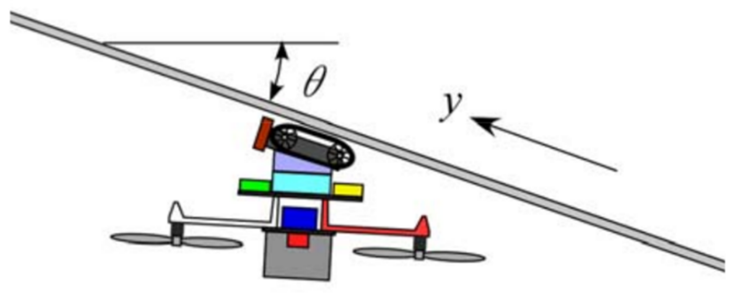
3.7.1. Unmanned Aerial Vehicles
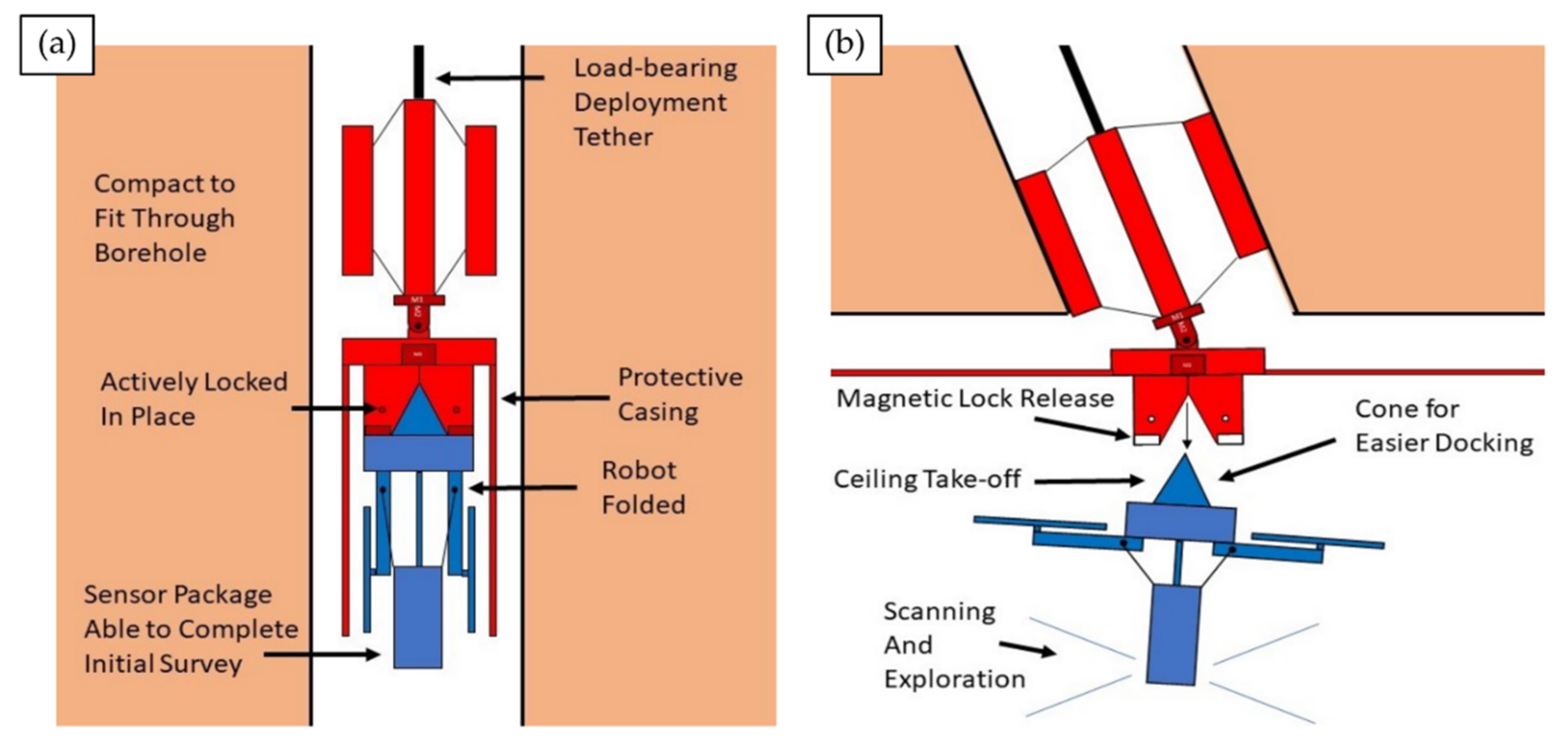
3.7.2. Adaptive Robots
3.8. BIM-Integration
3.9. Other Methods
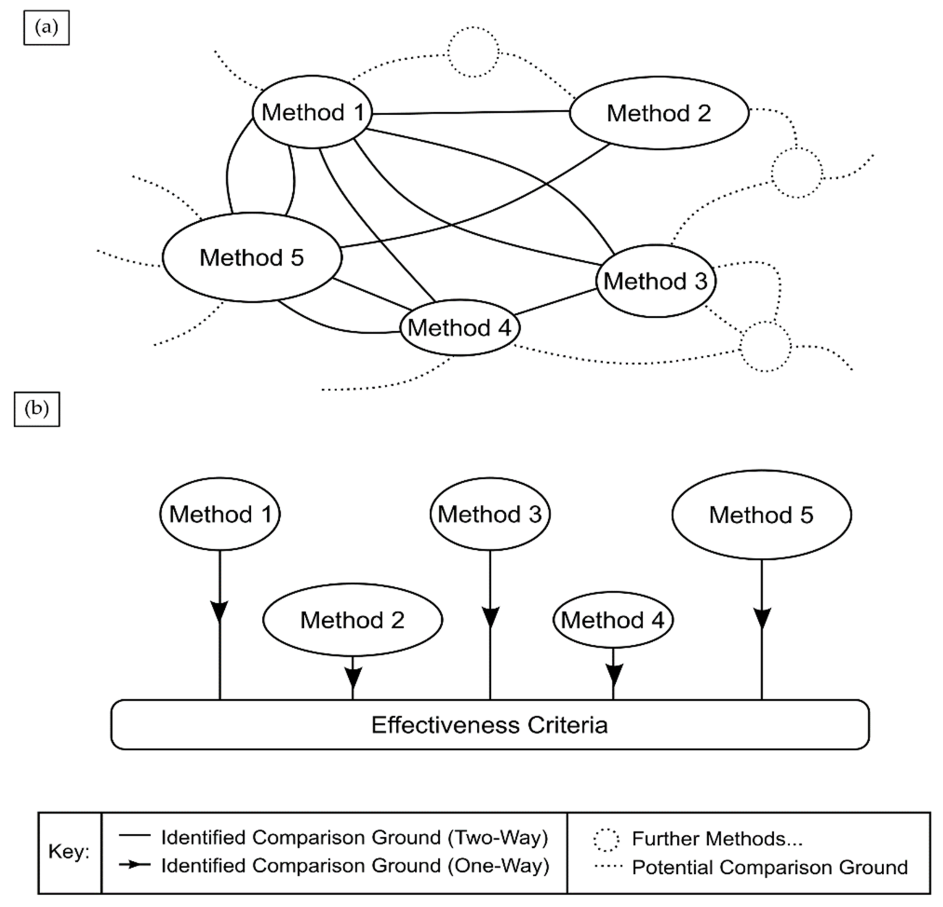
4. Heuristic Comparisons of RTI Methods
- Ambiguity maintaining a consistent comparative ground throughout;
- Contextual variation between significance of comparative grounds.
“Let’s compare the accuracy of subsurface 3D visuals produced by LiDAR and pseudo-3DGPR. The latter are clearly more accurate because LiDAR can only indirectly visualise the subsurface (cross-sectional deformation). But the former is more accurate because deformation appears as point cloud deformation, whereas physical features are not actually hyperbolae-shaped as they’re shown in pseudo-3DGPR”.
“The spatial resolution of gravitational surveys would be inferior to Thermography for detecting small voids in an operating tunnel, but superior for strata mapping during construction”.
5. Criteria for an ‘Effective’ RTSSI Visualisation Framework
- Data Acquisition:
- Completeness—Uninterrupted scan coverage should be achieved to record the full extent of the influential regions of the tunnel subsurface. Current methods either lack deep penetrative capability or exhibit bind spots due high localisation of scans or geometry curvature.
- Duration—Survey execution should balance acquisition speeds with recovered data quality (i.e., resolution, distortions) ensuring inspections and repairs cause minimal network disruption. A rapid low-quality scan limits inspection closure, but misinformed repairs take longer to fix and vice versa.
- Information Conveyance:
- Accessibility/Interpretive Clarity—A railway network end-user who is not a specialist in the utilised RTSSI technique(s) (e.g., planner) should independently be able to understand and make informed decisions based on visualisation output (consider radargrams the antithesis to this, containing considerable but mostly incomprehensible information).
- Faithfulness—Inconsistency between the physical subsurface geometry undergoing inspection and corresponding representation within the visualisation medium should be kept to a minimum. An example of unfaithful conveyance is how overhead structures can confusingly appear as below-ground features (airwaves) in radargrams [93,210].
- Interactivity—Visualisations should react intuitively to end-user engagement in ways that make surveys more ergonomic, efficient and versatile. Again consider radargrams; time-slicing in pseudo-3DGPR conveys depth more ergonomically than viewing am isolated B-scan.
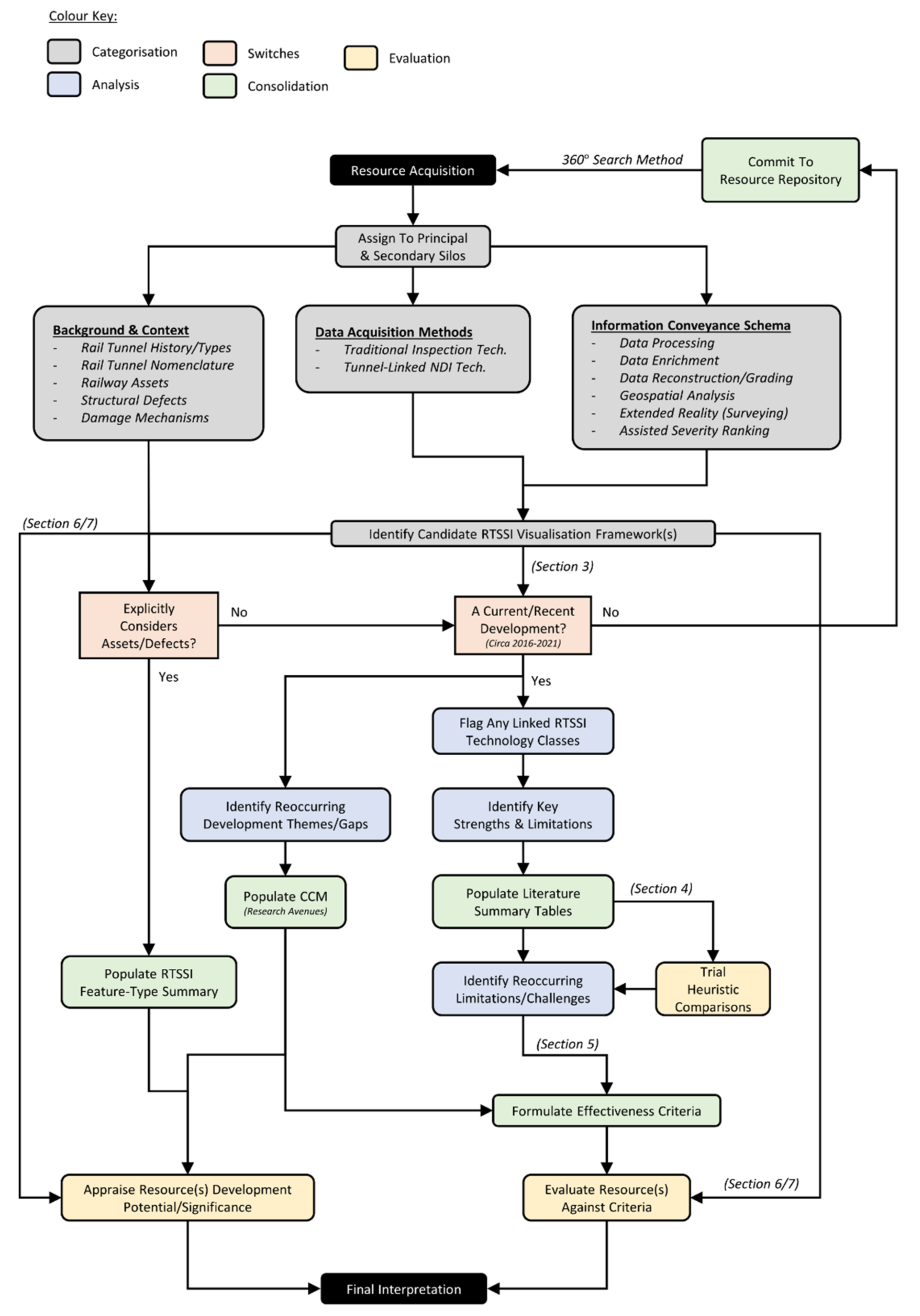
6. Steps towards Criteria Fulfilment
6.1. Automated Feature Detection and Evaluation
6.1.1. Common Assets in Masonry Railway Tunnels
- Ventilation Shafts—Hollow columns extending from tunnel crown to the surface. They facilitate air circulation and were originally used to remove material during construction [227].
- Maintenance Shafts—To allow simultaneous excavation of multiple faces, many shafts would be sunk along proposed tunnel routes [228]. Typically infilled or converted to ventilation shafts, capping frequently conceals them for aesthetics (processes rarely recorded in writing). Being unreinforced, many have deformed or partially collapsed.
- c
- Overhead Line Equipment (OLE)—Furthermore, dubbed ‘traction wires’ or the ‘catenary’, these high voltage electrical pickup lines power electric locomotives via onboard pantograph connectors. Systems can be integrated into older tunnels during electrification works. Forms include tensioned metallic cables mounted to the crown and the Rigid Overhead Conductor Rail System (ROCS) [231], which provide more efficient operation in low-clearance tunnels. Structural weakening can result from necessary drilling during install, whilst strong electromagnetic fields generated by the power feed can interfere with data acquisition systems and present line of sight obstruction during haunch or crown inspections.
- d
- Portals—Reinforced surfaces surrounding tunnel entrances combating outward deformation induced by shear stresses from continuous shifting of landmass encircling the tunnel [232]. Exposed to the elements, portal rigidity deteriorates, risking collapse if cracks and displacement are not detected early. Reinforcement schemes include buttresses, ground anchors, and steel mesh coverage fixed with soil nails [233].
- e
- Refuges—Small arched recesses within the tunnel lining to protect railway workers from locomotives.
- f
- Buried Utilities—These can include both metallic and plastic water drainage pipes [234], electrical wiring and telecom cables.
- g
- Trackside Objects—These include signage, signals, electrical junction boxes and CCTV units.
- h
- Culverts—Small passages allowing watercourses to pass under railway tracks, including underground rivers [235]. Old masonry culverts particularly can be weakened by solution and hydraulic action resulting in partial section collapse, deforming the railbed above and causing water backlog which floods tunnels.
6.1.2. Common Defects in Masonry Railway Tunnels
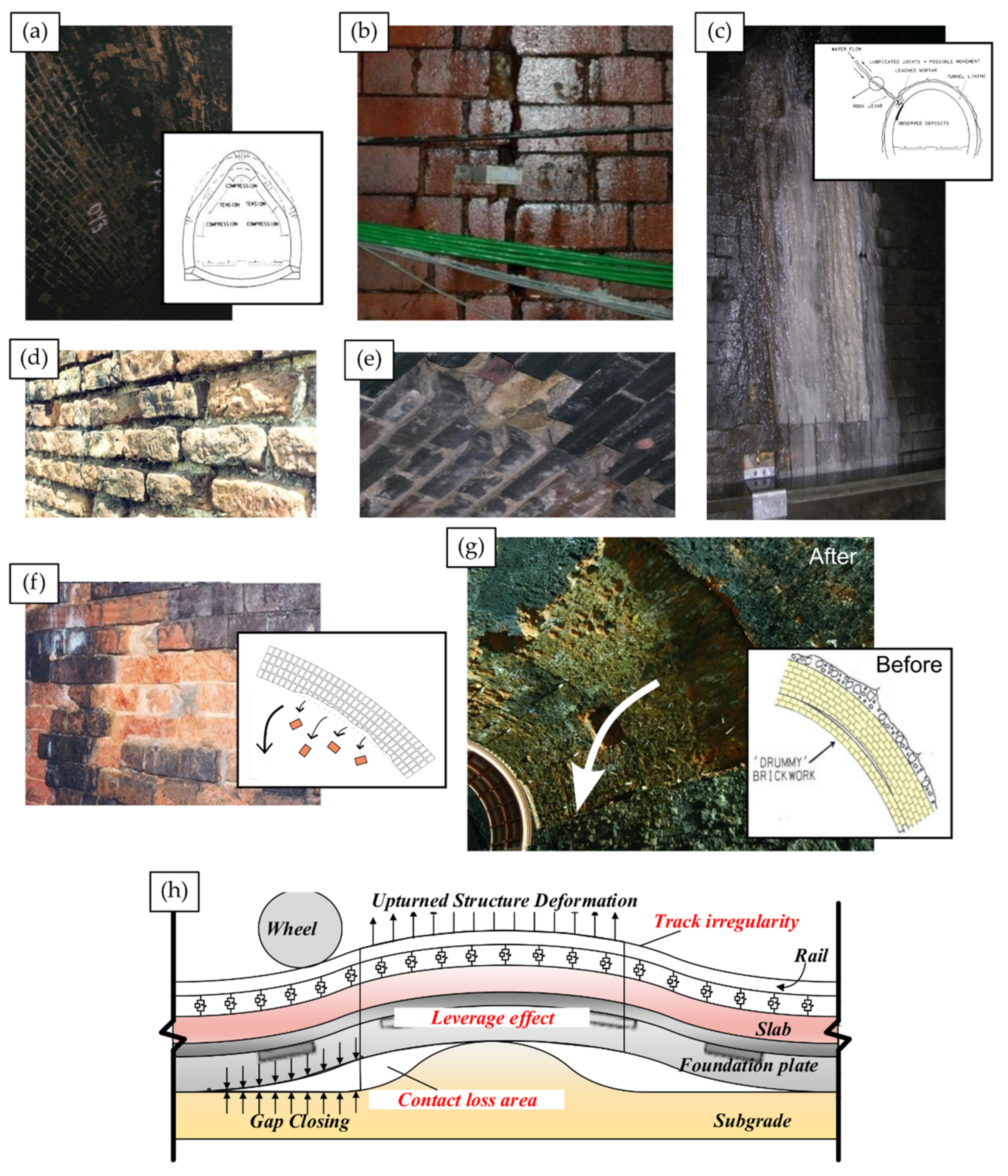
- Arch Barrel and Cross Sectional Deformations (Figure 12a)—Shifting tunnel landmass induces changeable tensile and compressive forces within arch barrels. This can trigger sidewall bulging and buckling; haunch distortion; tunnel floor bowing or side-offset of the crown.
- Cracks and Fracturing (Figure 12b)—Localised shear forces and vibrations from rolling stock can split and displace masonry. Damage ranges from hairline cracks lacking obvious signs of displacement, to large open fractures exhibiting significant displacement.
- Water Ingress (Figure 12c)—Rain infiltrates tunnels through shafts and groundwater propagates through dissolved subsurface joints and fissures (karsts) [236]. Leaching of mortar begins as water percolates between masonry before flowing down the sidewall. Lubrication of masonry joints leads to movement of the structure, resulting in lining deformation. Owing to joint length, significant quantities of ingress can accumulate, scouring supports and flooding tunnels without proper drainage or saturated catchpits, as ingress often carries dissolved ochre (acquired during subsurface percolation) which forms crystalised limonite deposits [197] that block drains. Out-flow down sidewalls forms noticeable white streaks emanating from the region of breech, therefore can be used as indicators of ingress source. However, establishing subsurface mortar leaching extent is reliant on NDI methods for RTSSI.
- Open Joints and Perished Mortar (Figure 12d)—Characterised by the deterioration and eventual absence of mortar between brickwork. As brick tunnels can date back over 150 years, mortar naturally begins to deteriorate from reactions with moisture in the bricks, air and subsurface [227,231,237]. This process is accelerated by wash from nearby ingress, vibrations induced by both rolling stock and air-pressure waves from passing locomotives.
- Loose and Missing Brickwork (Figure 12e)—Early onset of spalling and failed patching repairs can result in loosened or missing brickwork, indicated by brickwork rubble on the railbed. Individually, gaps pose no substantial loss of structural rigidity, but can provide opportunity for larger defect growth if not addressed quickly. Furthermore, if present in tunnel haunch or crown, falling rubble can damage rolling stock, or cause serious injury to ground crews working below.
- f
- Spalling (Figure 12f)—Perishing masonry on the tunnel intrados in vicinity of the haunch or crown can be dislodged by gravity, leaving the next layer of brickwork exposed. Repetition gradually creates rough-profiled recessed quadrants. Bricks in newly exposed layers lack tarnishing from exposure to soot and locomotive exhaust fumes, thus a second hallmark is more vibrant brickwork colouration.
- g
- Ring Separation and Debonding (Figure 12g)—Arch barrels contain multiple layers of concentric brickwork rings. Literature encountered discussed brick tunnels ranging from 3–15 layers [237,239,240], evidencing significant possible contextual variation. Ingress, deterioration of intrados mortar and poor quality workmanship can all cause neighbouring rings to separate within the wall. Gravity pulls innermost layers downward, causing debonding from layers behind forming slit voids (subsurface hairline fractures). Over time, large voids begin to grow. If near-surface, separating rings may briefly cause visible cracking of intrados mortar, allowing detection. However, separations deeper than a single ring are completely invisible to an in-tunnel observer. With time, large sections of rings can debond, causing arcs of brickwork to fall away as slabs. Such ‘delamination’ events can deform rails or damage the railbed presenting a derailment risk. Depending on size, debonding can significantly weaken substantial volumes of surrounding masonry.
- h
- Railbed Faults (Figure 12i)—Subgrade layers of ballast facilitate even distribution of rail-traffic weight, ensuring rails remains level on uneven ground to prevents derailments. Displacement induced by ballast fouling [75,76,77] and frost heave [238,241,242] can damage rails and offsets train weight distribution, increasing in-tunnel derailment risk and subsequent likelihood of major network disruptions.
- i
- Drainage Faults—Tunnels contain integrated pipework and catchment pits to safely remove excess water and silt. Flooding may occur if pipes become blocked, rupture due to freezing and expansion, or become overwhelmed by intense weather events [243]. Improvement works can also fail. For example, 18 bolts supporting a water catchment tray in Balcombe Tunnel (2011) decoupled due to resin failure [244]. Sag reduced tunnel clearance from 0.87 m to 0.3 m posing a dangerous obstruction to rail-traffic.
6.2. Extended Reality for Dynamic Survey Interaction
7. Discussion
Supplementary Materials
Author Contributions
Funding
Institutional Review Board Statement
Informed Consent Statement
Data Availability Statement
Acknowledgments
Conflicts of Interest
Abbreviations
Appendix A

| Symbol | Clarity | Necessary Training |
|---|---|---|
| ○○○ | High | Training Not Required. |
| ○○● | Mid-High | Some Require Light Training. |
| ○●● | Low-Mid | Most Require Moderate Training. |
| ●●● | Low | Extensive Training Essential. |
| Column Field | Type | Shorthand |
|---|---|---|
| Status | Concept | C |
| Prototype | P | |
| Commercial System | CS | |
| Motion | Static | ST |
| Handheld | HH | |
| On-Rail | OR | |
| Airborne | AB | |
| Crawler-Unit | CU | |
| Robotic Arm | RA | |
| Adaptive Traction Unit | ATU | |
| Pneumatic Suction Feet | PSF | |
| Tunnel Boring Machine | TBM | |
| Duration | Seconds | S |
| Minutes | M | |
| Hours | H | |
| Days | D | |
| Weeks | W | |
| Key Target Types | Cross Sectional Deformation | CSD |
| Hot/Cold Spots | H/C | |
| Groundwater Flow | GF | |
| Buried Utilities | BU | |
| Ballast Fouling | BF | |
| Trackside Assets | TA | |
| Power Distribution | PD | |
| Voids/Debonding | V/D | |
| Ore-Deposits | OD | |
| Additional Symbols | Not Applicable | N/A |
| Information Unavailable | - | |
| Important Note | * |
References
- Jones, C. Transportation planning in an era of inequality and climate change. Fordham Urban Law J. 2017, 44, 1005–1009. [Google Scholar]
- Wan, M.; Standing, J.; Potts, D.; Burland, J. Measured short-term subsurface ground displacements from EPBM tunnelling in London clay. Geotechnique 2017, 67, 748–779. [Google Scholar] [CrossRef]
- Zhang, X.; Jiang, Y.; Sugimoto, S. Seismic damage assessment of mountain tunnel: A case study on the Tawarayama tunnel due to the 2016 Kumamoto earthquake. Tunn. Undergr. Space Technol. 2018, 71, 138–148. [Google Scholar] [CrossRef] [Green Version]
- Attard, L.; Debono, C.; Valentino, G.; Di Castro, M.; Osborne, J.; Scibile, L.; Ferre, M. A comprehensive Virtual Reality System for Tunnel Surface Documentation and Structural Health Monitoring. In Proceedings of the 2018 IEEE International Conference on Imaging Systems and Techniques (IST), Krakow, Poland, 16–18 October 2018; pp. 1–6. [Google Scholar]
- Palin, E.; Stipanovic Oslakovic, I.; Gavin, K.; Quinn, A. Implications of climate change for railway infrastructure. Wiley Interdiscip. Rev. Clim. Chang. 2021, 12, 1–47. [Google Scholar] [CrossRef]
- Bickerdike, G. Forgotten Relics of an Enterprising Age. Organisation Website. 2017. Available online: http://www.forgottenrelics.co.uk/glossary/index.html (accessed on 22 November 2021).
- Shillito, C. The Fiery Jack. Railway & Canal Historical Society 2007. Volume 774. Available online: https://rchs.org.uk/wpcontent/uploads/2020/02/Journal-200-Dec-2007.pdf#page=40 (accessed on 27 July 2021).
- Prakhya, G.; Hopkin, I.; Hansford, B. Construction of a Concrete Segmental Arch Bridge Over a Railway. In Institution of Civil Engineers-Bridge Engineering; Thomas Telford Ltd.: London, UK, 2019; Volume 172, pp. 226–240. [Google Scholar] [CrossRef]
- Liu, F.; Ma, T.; Tang, C.; Liu, X.; Chen, F. A case study of collapses at the Yangshang tunnel of the coal transportation channel from the western inner Mongolia to the central China. Tunn. Undergr. Space Technol. 2019, 92, 103063. [Google Scholar] [CrossRef]
- Montero, R.; Victores, J.; Martinez, S.; Jardón, A.; Balaguer, C. Past, present and future of robotic tunnel inspection. Autom. Constr. 2015, 59, 99–112. [Google Scholar] [CrossRef]
- Farahani, B.; Barros, F.; Sousa, P.; Cacciari, P.; Tavares, P.; Futai, M.; Moreira, P. A coupled 3D laser scanning and digital image correlation system for geometry acquisition and deformation monitoring of a railway tunnel. Tunn. Undergr. Space Technol. 2019, 91, 102995. [Google Scholar] [CrossRef]
- Bahadori-Jahromi, A.; Rotimi, A.; Roxan, A. Sustainable conditional tunnel inspection: London underground, UK. Infrastruct. Asset Manag. 2018, 5, 22–31. [Google Scholar] [CrossRef]
- Liu, S.; Wang, Q.; Luo, Y. A review of applications of visual inspection technology based on image processing in the railway industry. Transp. Saf. Environ. 2019, 1, 185–204. [Google Scholar] [CrossRef] [Green Version]
- Stent, S.; Girerd, C.; Long, P.; Cipolla, R. A Low-Cost Robotic System for the Efficient Visual Inspection of Tunnels. In Proceedings of the International Symposium on Automation and Robotics in Construction, Oulu, Finland, 15–18 June 2015; IAARC Publications: Oulu, Finland, 2015; Volume 32. Available online: http://mi.eng.cam.ac.uk/~cipolla/archive/Publications/inproceedings/2015-ISARC-tunnel-inspection.pdf (accessed on 13 July 2021).
- Attard, L.; Debono, C.; Valentino, G.; Di Castro, M. Image Mosaicing of Tunnel Wall Images Using High Level Features. In Proceedings of the 10th International Symposium on Image and Signal Processing and Analysis, Ljubljana, Slovenia, 18–20 September 2017; pp. 141–146. [Google Scholar]
- Tannant, D. Review of photogrammetry-based techniques for characterization and hazard assessment of rock faces. Int. J. Georesour. Environ. IJGE 2015, 1, 76–87. [Google Scholar] [CrossRef]
- Krisada, C.; Tae-Kyun, K.; Fabio, V.; Roberto, C.; Kenichi, S. Distortion-free image mosaicing for tunnel inspection based on robust cylindrical surface estimation through structure from motion. J. Comput. Civ. Eng. 2016, 30, 04015045. [Google Scholar] [CrossRef]
- Jenkins, M.D.; Buggy, T.; Morison, G. An Imaging System for Visual Inspection and Structural Condition Monitoring of Railway Tunnels. In Proceedings of the 2017 IEEE Workshop on Environmental, Energy, and Structural Monitoring Systems (EESMS), Milan, Italy, 24–25 July 2017; pp. 1–6. [Google Scholar]
- Xue, Y.; Zhang, S.; Zhou, M.; Zhu, H. Novel SfM-DLT method for metro tunnel 3D reconstruction and visualization. Undergr. Space 2021, 6, 134–141. [Google Scholar] [CrossRef]
- Aleksieva, N.; Hermosilla Carrasco, C.; Brown, A.; Dean, R.; Carolin, A.; Täljsten, B.; García-Villena, F.; Morales-Gamiz, F. Inspection and Monitoring Techniques for Tunnels and Bridges; Technical Report, IN2TARCK2; Research into Enhanced Tracks, Switches and Structures: Málaga, Spain, 2019. [Google Scholar] [CrossRef]
- Mccormick, N.; Kimkeran, S.; Najimi, A.; Jonas, D. Assessing the Condition of Railway Assets Using DIFCAM: Results from Tunnel Examinations. In Proceedings of the 6th IET Conference on Railway Condition Monitoring (RCM 2014), Birmingham, UK, 17–18 September 2014; pp. 1–6. [Google Scholar] [CrossRef]
- Npl Management Limited. DIFCAM Evolution. Organisation Website. 2021. Available online: https://gtr.ukri.org/projects?ref=971711 (accessed on 13 July 2021).
- Xue, Y.; Zhang, S. A Fast Metro Tunnel Profile Measuring Method Based on Close-Range Photogrammetry. In Proceedings of the International Conference on Information Technology in Geo-Engineering, Guimaraes, Portugal, 29 September–2 October 2019; Springer: Cham, Switzerland, 2019; pp. 57–69. [Google Scholar] [CrossRef]
- Leonidas, E.; Xu, Y. The Development of an Automatic Inspection System Used for the Maintenance of Rail Tunnels. In Proceedings of the 2018 24th International Conference on Automation and Computing (ICAC), Newcastle Upon Tyne, UK, 6–7 September 2018; pp. 1–6. [Google Scholar] [CrossRef]
- IOWA State University. The Speed of Sound in Other Materials. Organisation Website. 2021. Available online: https://www.ndeed.org/Physics/Sound/speedinmaterials.xhtml (accessed on 15 June 2021).
- TWI Ltd. What Is Ultrasonic Testing and How Does It Work? Organisation Website. 2021. Available online: https://www.twiglobal.com/technical-knowledge/faqs/ultrasonic-testing (accessed on 17 June 2021).
- Whitlow, R.; Haskins, R.; Mccomas, S.; Crane, C.; Howard, I.; Mckenna, M. Remote bridge monitoring using infrasound. J. Bridge Eng. 2019, 24, 04019023. [Google Scholar] [CrossRef]
- White, J.; Wieghaus, K.; Karthik, M.; Shokouhi, P.; Hurlebaus, S.; Wimsatt, A. Nondestructive testing methods for underwater tunnel linings: Practical application at Chesapeake channel tunnels. J. Infrastruct. Syst. 2017, 23, B4016011. [Google Scholar] [CrossRef] [Green Version]
- Menendez, E.; Victores, J.; Montero, R.; Martínez, S.; Balaguer, C. Tunnel structural inspection and assessment using an autonomous robotic system. Autom. Constr. 2018, 87, 117–126. [Google Scholar] [CrossRef]
- Protopapadakis, E.; Stentoumis, C.; Doulamis, N.; Doulamis, A.; Loupos, K.; Makantasis, K.; Kopsiaftis, G.; Amditis, A. Autonomous robotic inspection in tunnels. ISPRS Ann. Photogramm. Remote Sens. Spat. Inf. Sci. 2016, 5, 167–174. [Google Scholar] [CrossRef]
- ROBO-SPECT. Robotic System with Intelligent Vision and Control for Tunnel Structural Inspection and Evaluation. Organisation Website. 2021. Available online: http://www.robo-spect.eu/index.php/project (accessed on 18 July 2021).
- Watanabe, A.; Even, J.; Morales, L.; Ishi, C. Robot-Assisted Acoustic Inspection of Infrastructures—Cooperative Hammer Sounding Inspection. In Proceedings of the 2015 IEEE/RSJ International Conference on Intelligent Robots and Systems (IROS), Hamburg, Germany, 28 September–2 October 2015; pp. 5942–5947. [Google Scholar] [CrossRef]
- Jamshidi, A.; Faghih Roohi, S.; Núñez, A.; Babuska, R.; De Schutter, B.; Dollevoet, R.; Li, Z. Probabilistic defect-based risk assessment approach for rail failures in railway infrastructure. IFAC-PapersOnLine 2016, 49, 73–77. [Google Scholar] [CrossRef]
- Fujii, H.; Yamashita, A.; Asama, H. Defect Detection with Estimation of Material Condition Using Ensemble Learning for Hammering Test. In Proceedings of the 2016 IEEE International Conference on Robotics and Automation (ICRA), Stockholm, Sweden, 16–21 May 2016; pp. 3847–3854. [Google Scholar] [CrossRef]
- Louhi Kasahara, J.Y.; Yamashita, A.; Asama, H. Acoustic inspection of concrete structures using active weak supervision and visual information. Sensors 2020, 20, 629. [Google Scholar] [CrossRef] [PubMed] [Green Version]
- Nakamura, S.; Yamashita, A.; Inoue, F.; Inoue, D.; Takahashi, Y.; Kamimura, N.; Ueno, T. Inspection test of a tunnel with an inspection vehicle for tunnel lining concrete. J. Robot. Mechatron. 2019, 31, 762–771. [Google Scholar] [CrossRef]
- Moreu, F.; Ayorinde, E.; Mason, J.; Farrar, C.; Mascarenas, D. Remote railroad bridge structural tap testing using aerial robots. Int. J. Intell. Robot. Appl. 2018, 2, 67–80. [Google Scholar] [CrossRef]
- Lattanzi, D.; Miller, G. Review of robotic infrastructure inspection systems. J. Infrastruct. Syst. 2017, 23, 1–15. [Google Scholar] [CrossRef]
- Sugimoto, T.; Sugimoto, K.; Uechi, I.; Utagawa, N.; Kuroda, C. Efficiency Improvement of Outer Wall Inspection by Noncontact Acoustic Inspection Method Using Sound Source Mounted Type UAV. In Proceedings of the 2019 IEEE International Ultrasonics Symposium (IUS), Glasgow, UK, 6–9 October 2019; pp. 2091–2094. [Google Scholar] [CrossRef]
- Arastounia, M. Automated as-built model generation of subway tunnels from mobile LIDAR data. Sensors 2016, 16, 1486. [Google Scholar] [CrossRef] [PubMed] [Green Version]
- Soilán, M.; Sánchez-rodríguez, A.; Del Río-barral, P.; Perez-Collazo, C.; Arias, P.; Riveiro, B. Review of laser scanning technologies and their applications for road and railway infrastructure monitoring. Infrastructures 2019, 4, 58. [Google Scholar] [CrossRef]
- Fröhlich, Z. Z+F profiler®6007 Duo. Online Document. 2014. Available online: https://www.zf-laser.com/fileadmin/editor/Broschueren/Broschuere_PROFILER_6007_duo_E_compr.pdf (accessed on 16 July 2021).
- Cui, H.; Ren, X.; Mao, Q.; Hu, Q.; Wang, W. Shield Subway Tunnel Deformation Detection Based on Mobile Laser Scanning. Autom. Constr. 2019, 106, 102889. [Google Scholar] [CrossRef]
- Gézero, L.; Antunes, C. Automated three-dimensional linear elements extraction from mobile LIDAR point clouds in railway environments. Infrastructures 2019, 4, 46. [Google Scholar] [CrossRef] [Green Version]
- Kemp, D. 3D Crossrail Tunnel Scan Unwrapped into 2D for First Time. Online Document. 2016. Available online: https://www.constructionnews.co.uk/tech/3d-crossrailtunnel-scan-unwrapped-into-2d-for-first-time-03-08-2016/#Tunnel_slice (accessed on 19 July 2021).
- Tan, K.; Cheng, X.; Ju, Q. Combining mobile terrestrial laser scanning geometric and radiometric data to eliminate accessories in circular metro tunnels. J. Appl. Remote Sens. 2016, 10, 030503. [Google Scholar] [CrossRef]
- Mccrory, K. Case Study of Llandudno Junction Station Survey. Online Document. 2020. Available online: https://scantechinternational.com/case_study/llandudno-junction-station (accessed on 16 July 2021).
- Scantech International Ltd. Railway Surveys. Organisation Website. 2021. Available online: https://scantechinternational.com/sectors/railway-surveys (accessed on 24 July 2021).
- Cheng, X.; Hu, X.; Tan, K.; Wang, L.; Yang, L. Automatic detection of shield tunnel leakages based on terrestrial mobile LIDAR intensity images using deep learning. IEEE Access 2021, 9, 55300–55310. [Google Scholar] [CrossRef]
- Fröhlich, Z. Case Study: Train Mounted Laser Survey of Birmingham New Street Area Resignalling Phase 7. Online Document. 2016. Available online: https://www.zf-laser.com/fileadmin/editor/Case_studies/Case_Study_omnicom_E_comp.pdf (accessed on 16 July 2021).
- Heinz, E.; Mettenleiter, M.; Kuhlmann, H.; Holst, C. Strategy for determining the stochastic distance characteristics of the 2D laser scanner Z+F Profiler 9012a with special focus on the close range. Sensors 2018, 18, 2253. [Google Scholar] [CrossRef] [Green Version]
- Sun, H.; Xu, Z.; Yao, L.; Zhong, R.; Du, L.; Wu, H. Tunnel monitoring and measuring system using mobile laser scanning: Design and deployment. Remote Sens. 2020, 12, 730. [Google Scholar] [CrossRef] [Green Version]
- Yamazaki, F.; Ueda, H.; Liu, W. Basic study on detection of deteriorated RC structures using infrared thermography camera. Eng. J. 2018, 22, 233–242. [Google Scholar] [CrossRef]
- Farahani, B. Innovative Methodology for Railway Tunnel Inspection. Ph.D. Thesis, Faculty of Engineering, University of Porto, Porto, Portugal, 2019. Available online: https://www.researchgate.net/publication/336406410_Innovative_Methodology_for_Railway_Tunnel_Inspection (accessed on 12 July 2021).
- Ishikawa, M.; Koyama, M.; Kasano, H.; Ogasawara, N.; Yamada, Y.; Hatta, H.; Fukui, R.; Nishitani, Y.; Utsunomiya, S. Inspection of Concrete Structures Using the Active Thermography Method with Remote Heating Apparatuses. In Proceedings of the 15th Asia Pacific Conference for Non-Destructive Testing (APCNDT2017), Singapore, 13–17 November 2017. [Google Scholar]
- Lu, X.; Tian, G.; Wu, J.; Gao, B.; Tian, P. Pulsed air-flow thermography for natural crack detection and evaluation. IEEE Sens. J. 2020, 20, 8091–8097. [Google Scholar] [CrossRef]
- Liu, Z.; Gao, B.; Tian, G. Natural crack diagnosis system based on novel l-shaped electromagnetic sensing thermography. IEEE Trans. Ind. Electron. 2020, 67, 9703–9714. [Google Scholar] [CrossRef]
- Konishi, S.; Kawakami, K.; Taguchi, M. Inspection method with infrared thermometry for detect void in subway tunnel lining. Procedia Eng. 2016, 165, 474–483. [Google Scholar] [CrossRef]
- Afshani, A.; Akagi, H. Investigate the Detection Rate of Defects in Concrete Lining Using Infrared-Thermography Method. In Proceedings of the 7th Japan-China Geotechnical Symposium, Sanya, China, 16–18 March 2018; pp. 1005–1016. Available online: https://www.researchgate.net/publication/324890164_Investigate_the_detection_rate_of_defects_in_concrete_lining_using_infrared-thermography_method (accessed on 14 July 2021).
- Olmi, R.; Palombi, L.; Durazzani, S.; Poggi, D.; Renzoni, N.; Costantino, F.; Durazzani, S.; Frilli, G.; Raimondi, V. Integrating thermographic images in a user-friendly platform to support inspection of railway bridges. Proceedings 2019, 27, 12. [Google Scholar] [CrossRef] [Green Version]
- Liu, F.; Seipel, S. Infrared-visible image registration for augmented reality-based thermographic building diagnostics. Vis. Eng. 2015, 3, 16. [Google Scholar] [CrossRef]
- Afshani, A.; Kawakami, K.; Konishi, S.; Akagi, H. Study of infrared thermal application for detecting defects within tunnel lining. Tunn. Undergr. Space Technol. 2019, 86, 186–197. [Google Scholar] [CrossRef]
- Scintrex. CG-3/3M Autograv Automated Gravity Meter Operator Manual, 5th ed.; Scintrex: Vaughan, ON, Canada, 1995; Available online: https://scintrexltd.com/support/product-manuals/cg3-manual/ (accessed on 27 November 2021).
- Butler, D. Detection and Characterization of Cavities, Tunnels, and Abandoned Mines. Online Document. 2008. Available online: https://digital.lib.usf.edu//content/SF/S0/05/54/94/00001/K26-05045-Butler--ICEEG_Presentation_on_Cavities_and_Tunnels.pdf (accessed on 14 November 2020).
- Fores, B.; Champollion, C.; Lesparre, N.; Pasquet, S.; Martin, A.; Nguyen, F. Variability of the water stock dynamics in karst: Insights from surface-to-tunnel geophysics. Hydrogeol. J. 2021, 29, 2077–2089. [Google Scholar] [CrossRef]
- Blecha, V.; Mašín, D. Observed and calculated gravity anomalies above a tunnel driven in clays–implication for errors in gravity interpretation. Near Surf. Geophys. 2013, 11, 569–578. [Google Scholar] [CrossRef] [Green Version]
- Zahorec, P.; Papčo, J.; Vajda, P.; Szabó, S. High-precision local gravity survey along planned motorway tunnel in the Slovak karst. Contrib. Geophys. Geod. 2019, 49, 207–227. [Google Scholar] [CrossRef] [Green Version]
- Bloedau, E. Assessment of Change to Gravity Field due to Underground Railroad Tunnel Construction. Ph.D. Thesis, University of Stuttgart, Stuttgart, Germany, 2021. Available online: https://elib.uni-stuttgart.de/handle/11682/11296 (accessed on 14 June 2021).
- Han, R.; Li, W.; Cheng, R.; Wang, F.; Zhang, Y. 3D high-precision tunnel gravity exploration theory and its application for concealed inclined high-density ore deposits. J. Appl. Geophys. 2020, 180, 104119. [Google Scholar] [CrossRef]
- Alani, A.; Tosti, F. GPR Applications in Structural Detailing of a Major Tunnel Using Different Frequency Antenna Systems. Constr. Build. Mater. 2018, 158, 1111–1122. [Google Scholar] [CrossRef]
- Lai, W.; Derobert, X.; Annan, P. A review of ground penetrating radar application in civil engineering: A 30-year journey from locating and testing to imaging and diagnosis. NDTE Int. 2018, 96, 58–78. [Google Scholar]
- Sensors & Software. What Is Ground Penetrating Radar (GPR)? Online Document. 2020. Available online: https://www.sensoft.ca/blog/what-is-gpr/ (accessed on 17 November 2020).
- Solla, M.; Pérez-Gracia, V.; Fontul, S. A Review of GPR Application on Transport Infrastructures: Troubleshooting and Best Practices. Remote Sens. 2021, 13, 672. [Google Scholar] [CrossRef]
- Shrestha, S.; Arai, I. Signal processing of ground penetrating radar using spectral estimation techniques to estimate the position of buried targets. EURASIP J. Adv. Signal Process. 2003, 2003, 970543. [Google Scholar] [CrossRef]
- Anbazhagan, P.; Dixit, P.; Bharatha, T. Identification of type and degree of railway ballast fouling using ground coupled GPR antennas. J. Appl. Geophys. 2016, 126, 183–190. [Google Scholar] [CrossRef]
- Cafiso, S.; Capace, B.; D’Agostino, C.; Delfino, E.; Di Graziano, A. Application of NDT to Railway Track Inspections. In Proceedings of the 3rd International Conference on Traffic and Transport Engineering (ICTTE), Lucerne, Switzerland, 6–10 July 2016. [Google Scholar]
- Ciampoli, L.; Calvi, A.; D’Amico, F. Railway ballast monitoring by GPR: A test-site investigation. Remote Sens. 2019, 11, 2381. [Google Scholar] [CrossRef] [Green Version]
- Proceq. Proceq GPR Live. Proceq, Screening Eagle Technologies AG Ringstrasse 28603 Schwerzenbach Zürich Switzerland. 2017. Available online: https://www.screeningeagle.com/en/product-family/proceq-ground-penetrating-radars (accessed on 3 October 2020).
- GSSI. StructureScan Mini XT. Online Document. 2017. Available online: https://www.geophysical.com/wp-content/uploads/2018/01/GSSI-StructureScanMiniXTBrochure.pdf (accessed on 21 July 2021).
- Proceq. Portable Ground Penetrating Radar—Proceq GP8000. Organisation Website. 2021. Available online: https://www.screeningeagle.com/en/products/proceq-gp8000-portable-concrete-gpr-radar (accessed on 12 June 2021).
- Dawood, T.; Zhu, Z.; Zayed, T. Deterioration mapping in subway infrastructure using sensory data of GPR. Tunn. Undergr. Space Technol. 2020, 103, 103487. [Google Scholar] [CrossRef]
- 3D-RADAR. GEOSCOPE MK IV: High-Speed 3D GPR with High-Resolution and Deep Penetration. Online Document. 2019. Available online: http://3d-radar.com/wp-content/uploads/2019/10/3DRadar_GeoScope_ProductSheet_2019.pdf (accessed on 18 June 2021).
- Zetica Rail. Zetica—Advanced Rail Radar (ZARR) Solution to Augment Inspection Trains. Organisation Website. 2021. Available online: https://zeticarail.com/systems-software/zarr/ (accessed on 4 July 2021).
- IDS GeoRadar. SRS SafeRailSystem: Safe Railway Ballast Inspections with Ground Penetrating Radar. Organisation Website. 2021. Available online: https://idsgeoradar.com/products/ground-penetratingradar/srs-saferailsystem (accessed on 4 July 2021).
- Zan, Y.; Li, Z.; Su, G.; Zhang, X. An innovative vehicle-mounted GPR technique for fast and efficient monitoring of tunnel lining structural conditions. Case Stud. Nondestruct. Test. Eval. 2016, 6, 63–69. [Google Scholar] [CrossRef] [Green Version]
- Xiong, H.; Su, G.; Zhang, C.; Li, B.; Wei, W. A train-mounted GPR System for Operating Railway Tunnel Inspection. In Advances in Transdisciplinary Engineering Series. In Proceedings of the ISMR 2020 7th International Symposium on Innovation & Sustainability of Modern Railway, Nanchang, China, 23–25 October 2020; Volume 14. Available online: https://ebooks.iospress.nl/volume/ismr-2020-proceedings-of-the-7th-international-symposium-on-innovation-amp-sustainability-of-modern-railway (accessed on 7 July 2020).
- Han, X.; Jin, J.; Wang, M.; Jiang, W.; Gao, L.; Xiao, L. A review of algorithms for filtering the 3D point cloud. Signal Process. Image Commun. 2017, 57, 103–112. [Google Scholar] [CrossRef]
- Rial, F.; Uschkerat, U. Improving SCR of Underground Target Signatures from Air-Launched GPR Systems Based on Scattering Center Extraction. In Proceedings of the 2017 18th International Radar Symposium (IRS), Prague, Czech Republic, 28–30 June 2017; pp. 1–10. [Google Scholar] [CrossRef]
- Xiang, Z.; Rashidi, A.; Ou, G. States of practice and research on applying GPR technology for labelling and scanning constructed facilities. J. Perform. Constr. Facil. 2019, 33, 03119001. [Google Scholar] [CrossRef]
- Lyu, Y.; Wang, H.; Gong, J. GPR detection of tunnel lining cavities and reverse-time migration imaging. Appl. Geophys. 2020, 17, 1–7. [Google Scholar] [CrossRef]
- Bugarinović, V.; Pajewski, L.; Ristić, A.; Vrtunski, M.; Govedarica, M.; Borisov, M. On the introduction of canny operator in an advanced imaging algorithm for real-time detection of hyperbolas in ground-penetrating radar data. Electronics 2020, 9, 541. [Google Scholar] [CrossRef] [Green Version]
- Li, C.; Xing, S.; Lauro, S.; Su, Y.; Dai, S.; Feng, J.; Cosciotti, B.; Di Paolo, F.; Mattei, E.; Xiao, Y.; et al. Pitfalls in GPR data interpretation: False reflectors detected in lunar radar cross sections by Chang’e-3. IEEE Trans. Geosci. Remote Sens. 2018, 56, 1325–1335. [Google Scholar] [CrossRef]
- Johnston, G. The Basics of Interpreting GPR Data—Part 2. Webinar. 2018. Available online: https://www.sensoft.ca/trainingevents/webinars/interpreting-gpr-data-part2/ (accessed on 16 November 2020).
- Kilic, G.; Eren, L. Neural network based inspection of voids and karst conduits in hydroelectric power station tunnels using GPR. J. Appl. Geophys. 2018, 151, 194–204. [Google Scholar] [CrossRef]
- Wang, X.; Sun, S.; Wang, J.; Yarovoy, A.; Neducza, B.; Manacorda, G. Real GPR signal processing for target recognition with circular array antennas. In Proceedings of the 2016 URSI International Symposium on Electromagnetic Theory (EMTS), Espoo, Finland, 14–18 August 2016; pp. 818–821. [Google Scholar] [CrossRef]
- Kim, N.; Kim, S.; An, Y.; Lee, J. A novel 3D GPR image arrangement for deep learning-based underground object classification. Int. J. Pavement Eng. 2019, 22, 740–751. [Google Scholar] [CrossRef]
- Šarlah, N.; Podobnikar, T.; Ambrožič, T.; Mušič, B. Application of kinematic GPR-TPS model with high 3D georeference accuracy for underground utility infrastructure mapping: A case study from urban sites in Celje, Slovenia. Remote Sens. 2020, 12, 1228. [Google Scholar] [CrossRef] [Green Version]
- Sjödin, R. Interpolation and Visualization of Sparse GPR Data. Master’s Thesis, Umea University, Department of Physics, Umea, Sweden, 2020. Available online: https://www.diva-portal.org/smash/record.jsf?pid=diva2:1431027&dswid=8251 (accessed on 30 July 2021).
- GoldenSoftwareLLC2015. Voxler®4: 3D Well & Volumetric Data Visualization. GoldenSoftwareLLC2015. 2015. Available online: https://downloads.goldensoftware.com/guides/Voxler4UserGuide.pdf (accessed on 12 December 2020).
- Zhang, S.; Zhang, L.; He, W.; Ling, T.; Deng, Z.; Fu, G. Three-dimensional quantitative recognition of filler materials ahead of a tunnel face via time-energy density analysis of wavelet transforms. Minerals 2022, 12, 234. [Google Scholar] [CrossRef]
- MALA. MALA Vision User Manual. GUIDELINE GEO, Hemvärnsgatan 9SE-171 54 Solna, Stockholm VAT: SE 556606-1155-01. 2021. Available online: https://www.guidelinegeo.com/product/mala-vision/ (accessed on 2 December 2021).
- Coli, M.; Ciuffreda, A.L.; Marchetti, E.; Morandi, D.; Luceretti, G.; Lippi, Z. 3D HBIM model and full contactless GPR tomography: An experimental application on the historic walls that support Giotto’s mural paintings, Santa Croce Basilica, Florence—Italy. Heritage 2022, 5, 132. [Google Scholar] [CrossRef]
- Hou, F.; Liu, X.; Fan, X.; Guo, Y. DL-aided underground cavity morphology recognition based on 3D GPR data. Mathematics 2022, 10, 2806. [Google Scholar] [CrossRef]
- Núñez-Nieto, X.; Solla, M.; Prego, F.J.; Lorenzo, H. Assessing the Applicability of GPR Method for Tunnelling Inspection: Characterization and Volumetric Reconstruction. In Proceedings of the 2015 8th International Workshop on Advanced Ground Penetrating Radar (IWAGPR), Florence, Italy, 7–10 July 2015; pp. 1–4. [Google Scholar] [CrossRef]
- Simi, A.; Manacorda, G. The NETTUN Project: Design of a GPR Antenna for a TBM. In Proceedings of the 2016 16th International Conference on Ground Penetrating Radar (GPR), Hong Kong, China, 13–16 June 2016; pp. 1–6. [Google Scholar] [CrossRef]
- Garcia-Garcia, F.; Valls-Ayuso, A.; Benlloch-Marco, J.; Valcuende-Paya, M. An optimization of the work disruption by 3D cavity mapping using GPR: A new sewerage project in Torrente (Valencia, Spain). Constr. Build. Mater. 2017, 154, 1226–1233. [Google Scholar] [CrossRef]
- Kadioglu, S.; Kadioğlu, Y. Determining buried remains under the ala gate road of Anavarza ancient city in the southern of Turkey with interactive transparent 3D GPR data imaging. Int. Multidiscip. Sci. Geoconf. Sgem 2019, 19, 773–779. [Google Scholar]
- Grasmueck, M.; Viggiano, D. PondView: Intuitive and Efficient Visualization of 3D GPR Data. In Proceedings of the 2018 17th International Conference on Ground Penetrating Radar (GPR), Rapperswil, Switzerland, 18–21 June 2018; pp. 1–6. [Google Scholar] [CrossRef]
- Agrafiotis, P.; Lampropoulos, K.; Georgopoulos, A.; Moropoulou, A. 3D modelling the Invisible Using Ground Penetrating radar. In The International Archives of the Photogrammetry, Remote Sensing and Spatial Information Sciences; Ktisis: Nafplio, Greece, 2017; Volume XLII/W3, pp. 33–37. [Google Scholar] [CrossRef] [Green Version]
- Tong, Z.; Gao, J.; Zhang, H. Recognition, location, measurement, and 3D reconstruction of concealed cracks using convolutional neural networks. Constr. Build. Mater. 2017, 146, 775–787. [Google Scholar] [CrossRef]
- Chen, K.; Kamezaki, M.; Katano, T.; Kaneko, T.; Azuma, K.; Ishida, T.; Seki, M.; Ichiryu, K.; Sugano, S. Compound locomotion control system combining crawling and walking for multi-crawler multi-arm robot to adapt unstructured and unknown terrain. Robomech J. 2018, 5, 2. [Google Scholar] [CrossRef] [Green Version]
- Neubauer, W.; Bornik, A.; Wallner, M.; Verhoeven, G. Novel Volume Visualisation of GPR Data Inspired by Medical Applications. In New Global Perspectives on Archaeological Prospection. In Proceedings of the 13th International Conference on Archaeological Prospection, Sligo, Ireland, 28 August–1 September 2019. [Google Scholar]
- Liu, Y.; Qiao, J.; Han, T.; Li, L.; Xu, T. A 3D image reconstruction model for long tunnel geological estimation. J. Adv. Transp. 2020, 2020, 8846955. [Google Scholar] [CrossRef]
- Feng, J.; Yang, L.; Wang, H.; Song, Y.; Xiao, J. GPR-Based Subsurface Object Detection and Reconstruction Using Random Motion and DepthNet. In Proceedings of the 2020 IEEE International Conference on Robotics and Automation (ICRA), Paris, France, 31 May 2020–31 August 2020; pp. 7035–7041. [Google Scholar] [CrossRef]
- Feng, J.; Yang, L.; Biao, J.; Xiao, J. Robotic inspection and 3D GPR-based reconstruction for underground utilities. arXiv 2021, arXiv:2106.01907. [Google Scholar]
- Dinh, K.; Gucunski, N.; Tran, K.; Novo, A.; Nguyen, T. Full-resolution 3D imaging for concrete structures with dual-polarization GPR. Autom. Constr. 2021, 125, 103652. [Google Scholar] [CrossRef]
- Pereira, M.; Burns, D.; Orfeo, D.; Zhang, Y.; Jiao, L.; Huston, D.; Xia, T. 3D multistatic ground penetrating radar imaging for augmented reality visualization. IEEE Trans. Geosci. Remote Sens. 2020, 58, 5666–5675. [Google Scholar] [CrossRef]
- Wu, S.; Hou, L.; Zhang, G. Integrated Application of Bm and Extended Reality Technology: A review, Classification and Outlook. In Proceedings of the International Conference on Computing in Civil and Building Engineering, São Paulo, Brazil, 18–20 August 2020; Springer: Berlin/Heidelberg, Germany, 2020; pp. 1227–1236. [Google Scholar] [CrossRef]
- Karaaslan, E.; Bagci, U.; Catbas, F. Artificial intelligence assisted infrastructure assessment using mixed reality systems. Transp. Res. Rec. 2019, 2673, 413–424. [Google Scholar] [CrossRef]
- Childs, J.; Orfeo, D.; Burns, D.; Huston, D.; Xia, T. Enhancing Ground Penetrating Radar with Augmented Reality Systems for Underground Utility Management. In Virtual, Augmented, and Mixed Reality (XR) Technology for Multi-Domain Operations; International Society for Optics and Photonics: Bellingham, WA, USA, 2020; Volume 11426, p. 1142608. [Google Scholar] [CrossRef]
- Jin, R. Developing a Mixed-Reality Based Application for Bridge Inspection and Maintenance. In Proceedings of the 20th International Conference on Construction Applications of Virtual Reality (CONVR 2020), Middlesbrough, UK, 30 September–2 October 2020. [Google Scholar]
- Hu, D.; Hou, F.; Blakely, J.; Li, S. Augmented Reality Based Visualization for Concrete Bridge Deck Deterioration Characterized by Ground Penetrating Radar. In Construction Research Congress 2020: Computer Applications; American Society of Civil Engineers: Reston, VA, USA, 2020; pp. 1156–1164. [Google Scholar] [CrossRef]
- Wei, L.; Magee, D.; Cohn, A. An anomalous event detection and tracking method for a tunnel look-ahead ground prediction system. Autom. Constr. 2018, 91, 216–225. [Google Scholar] [CrossRef] [Green Version]
- ESCAP. Inspection and Monitoring of Railway Infrastructure Using Aerial Drones. Online Document. 2019. Available online: https://www.unescap.org/sites/default/files/TARWG_4E_Inspectionandmonitoring.pdf (accessed on 1 July 2021).
- Tan, C.H.; Shaiful, D.S.B.; Ang, W.J.; Win, S.K.H.; Foong, S. Design optimization of sparse sensing array for extended aerial robot navigation in deep hazardous tunnels. IEEE Robot. Autom. Lett. 2019, 4, 862–869. [Google Scholar] [CrossRef]
- Jordan, S.; Moore, J.; Hovet, S.; Box, J.; Perry, J.; Kirsche, K.; Lewis, D.; Tse, Z. State-of-the-art technologies for UAV inspections. IET Radar Sonar Navig. 2018, 12, 151–164. [Google Scholar] [CrossRef]
- Galtarossa, L.; Navilli, L.; Chiaberge, M. Visual-Inertial Indoor Navigation Systems and Algorithms for UAV Inspection Vehicles. In Industrial Robotics; IntechOpen: London, UK, 2020; pp. 1–16. [Google Scholar] [CrossRef] [Green Version]
- Azevedo, F.; Oliveira, A.; Dias, A.; Almeida, J.; Moreira, M.; Santos, T.; Ferreira, A.; Martins, A.; Silva, E. Collision Avoidance for Safe Structure Inspection with Multirotor UAV. In Proceedings of the 2017 European Conference on Mobile Robots (ECMR), Paris, France, 6–8 September 2017; pp. 1–7. [Google Scholar] [CrossRef] [Green Version]
- Quan, Q.; Fu, R.; Li, M.; Wei, D.; Gao, Y.; Cai, K. Practical distributed control for VTOL UAVs to pass a tunnel. arXiv 2021, arXiv:2101.07578. [Google Scholar]
- Petrlík, M.; Báča, T.; Heřt, D.; Vrba, M.; Krajník, T.; Saska, M. A robust UAV system for operations in a constrained environment. IEEE Robot. Autom. Lett. 2020, 5, 2169–2176. [Google Scholar] [CrossRef]
- Moletta, M. Path Planning for Autonomous Aerial Robots in Unknown Underground Zones Optimized for Vertical Tunnels Exploration. Master’s Thesis, KTH Royal Institute of Technology in Stockholm, School of Electrical Engineering and Computer Science (EECS), Stockholm, Sweden, 2020. Available online: https://www.diva-portal.org/smash/record.jsf?pid=diva2:1499089&dswid=5052 (accessed on 18 March 2021).
- Elmokadem, T.; Savkin, A. A method for autonomous collision-free navigation of a quadrotor UAV in unknown tunnel-like environments. Robotica 2021, 40, 1–27. [Google Scholar] [CrossRef]
- Falcone, A.; Vaccarino, G. Primary Level UAV for Tunnel Inspection: The PLUTO Project. SEMANTIC SCHOLAR. 2020. Available online: https://www.semanticscholar.org/paper/Primary-Level-UAVfor-Tunnel-Inspection:-the-PLUTO-Falcone-Vaccarino/32a694d6dbe4f7dba61181c54d8681fbe7503245 (accessed on 18 July 2020).
- Özaslan, T.; Shen, S.; Mulgaonkar, Y.; Michael, N.; Kumar, V. Inspection of Penstocks and Featureless Tunnel-Like Environments Using Micro UAVs. In Field and Service Robotics: Results of the 9th International Conference; Mejias, L., Corke, P., Roberts, J., Eds.; Springer Tracts in Advanced Robotics Book Series; Springer International Publishing: Cham, Switzerland, 2015; Volume 105, pp. 123–136. [Google Scholar] [CrossRef]
- Sakuma, M.; Kobayashi, Y.; Emaru, T.; Ravankar, A. Mapping of Pier Substructure Using UAV. In Proceedings of the 2016 IEEE/SICE International Symposium on System Integration (SII), Sapporo, Japan, 13–15 December 2016; pp. 361–366. [Google Scholar] [CrossRef]
- Wu, W.; Qurishee, M.; Owino, J.; Fomunung, I.; Onyango, M.; Atolagbe, B. Coupling Deep Learning and UAV for Infrastructure Condition Assessment Automation. In Proceedings of the 2018 IEEE International Smart Cities Conference (ISC2), Kansas City, MO, USA, 16–19 September 2018; pp. 1–7. [Google Scholar] [CrossRef]
- Dorafshan, S.; Maguire, M.; Hoffer, N.; Coopmans, C. Challenges in Bridge Inspection Using Small Unmanned Aerial Systems: Results and Lessons Learned. In Proceedings of the 2017 International Conference on Unmanned Aircraft Systems (ICUAS), Miami, FL, USA, 13–16 June 2017; pp. 1722–1730. [Google Scholar] [CrossRef]
- Hovering Solutions Ltd. Case Studies: Penstock Inspections and Mapping by Using Autonomous Flying Robots. Organisation Website. 2020. Available online: http://www.hoveringsolutions.com/aboutus/penstocks-mapping (accessed on 19 April 2021).
- Tan, C.; Ng, M.; Shaiful, D.; Win, S.; Ang, W.; Yeung, S.; Lim, H.; Do, M.; Foong, S. A smart unmanned aerial vehicle (UAV) based imaging system for inspection of deep hazardous tunnels. Water Pract. Technol. 2018, 13, 991–1000. [Google Scholar] [CrossRef]
- Hovering Solutions Ltd. Case Studies: London Crossrail Tunnels Are Scanned Using Drones. Organisation Website. 2017. Available online: http://www.hoveringsolutions.com/about-us/crossrailtunnels-3d-mapping-using-drones (accessed on 19 April 2021).
- Pahwa, R.; Chan, K.; Bai, J.; Saputra, V.; Do, M.; Foong, S. Dense 3D Reconstruction for Visual Tunnel Inspection Using Unmanned Aerial Vehicle. In Proceedings of the 2019 IEEE/RSJ International Conference on Intelligent Robots and Systems (IROS), Macau, China, 3–8 November 2019; pp. 7025–7032. [Google Scholar] [CrossRef] [Green Version]
- Cwiakala, P.; Gruszczynski, W.; Stoch, T.; Puniach, E.; Mrochen, D.; Matwij, W.; Matwij, K.; Nedzka, M.; Sopata, P.; Wojcik, A. UAV applications for determination of land deformations caused by underground mining. Remote Sens. 2020, 12, 1733. [Google Scholar] [CrossRef]
- Garcia-Fernandez, M.; Alvarez-Lopez, Y.; Gonzalez-Valdes, B.; Arboleya-Arboleya, A.; Rodriguez-Vaqueiro, Y.; Heras, F.L.; Pino, A. UAV-Mounted GPR for NDT Applications. In Proceedings of the 2018 15th European Radar Conference (EuRAD), Madrid, Spain, 26–28 September 2018; pp. 2–5. [Google Scholar] [CrossRef] [Green Version]
- Garcia-Fernandez, M.; Alvarez-Lopez, Y.; Heras, F.L.; Gonzalez-Valdes, B.; Rodriguez-Vaqueiro, Y.; Pino, A.; Arboleya-Arboleya, A. GPR System Onboard a UAV for Non-Invasive Detection of Buried Objects. In Proceedings of the 2018 IEEE International Symposium on Antennas and Propagation USNC/URSI National Radio Science Meeting, Boston, MA, USA, 8–13 July 2018; pp. 1967–1968. [Google Scholar] [CrossRef] [Green Version]
- Lamsters, K.; Karušs, J.; Krievāns, M.; Ješkins, J. High-resolution surface and bed topography mapping of Russell Glacier (SW Greenland) using UAV and GPR. ISPRS Ann. Photogramm. Remote Sens. Spat. Inf. Sci. 2020, 2, 757–763. [Google Scholar] [CrossRef]
- MALA. MALA Geodrone 80 Technical Specification. GUIDELINEGEO, Hemvarnsgatan 9SE-171 54 Solna, StockholmVAT: SE 556606-1155-01. 2021. Available online: https://wwwguidelinegeoc.cdn.triggerfish.cloud/uploads/2020/01/MALA-GeoDrone-80-Technical-Specification-2020-04-27.pdf (accessed on 2 December 2021).
- Delamare, Q. Algorithms for Estimation and Control of Quadrotors in Physical Interaction with Their Environment. Ph.D. Thesis, University Rennes, Rennes, France, 2019. Available online: https://tel.archives-ouvertes.fr/tel-02410023 (accessed on 18 July 2021).
- Delamare, Q.; Giordano, P.; Franchi, A. Toward aerial physical locomotion: The contact-fly-contact problem. IEEE Robot. Autom. Lett. 2018, 3, 1514–1521. [Google Scholar] [CrossRef]
- Sanchez-Cuevas, P.; Ramon-Soria, P.; Arrue, B.; Ollero, A.; Heredia, G. Robotic system for inspection by contact of bridge beams using UAVs. Sensors 2019, 19, 305. [Google Scholar] [CrossRef] [Green Version]
- Kocer, B.; Tjahjowidodo, T.; Pratama, M.; Seet, G. Inspection-while-flying: An autonomous contact-based nondestructive test using UAV-tools. Autom. Constr. 2019, 106, 102895. [Google Scholar] [CrossRef]
- Iwamoto, T.; Enaka, T.; Tada, K. Development of testing machine for tunnel inspection using multi-rotor UAV. J. Phys. Conf. Ser. 2017, 842, 012068. [Google Scholar] [CrossRef] [Green Version]
- PRODRONE Co., Ltd. PD6-CI-L. Organisation Website. 2021. Available online: https://www.prodrone.com/products/pd6-ci-l/ (accessed on 19 July 2021).
- Mahmood, S.; Bakhy, S.; Tawfik, M. Propeller-Type Wall-Climbing Robots: A Review. IOP Conf. Ser. Mater. Sci. Eng. 2021, 1094, 012106. [Google Scholar] [CrossRef]
- Ikeda, T.; Yasui, S.; Fujihara, M.; Ohara, K.; Ashizawa, S.; Ichikawa, A.; Okino, A.; Oomichi, T.; Fukuda, T. Wall Contact by Octo-rotor UAV with one DoF Manipulator for Bridge Inspection. In Proceedings of the 2017 IEEE/RSJ International Conference on Intelligent Robots and Systems (IROS), Vancouver, BC, Canada, 24–28 September 2017; pp. 5122–5127. [Google Scholar] [CrossRef]
- Jiang, G.; Voyles, R.; Choi, J. Precision Fully-Actuated UAV for Visual and Physical Inspection of Structures for Nuclear Decommissioning and Search and Rescue. In Proceedings of the 2018 IEEE International Symposium on Safety, Security, and Rescue Robotics (SSRR), Philadelphia, PA, USA, , 6–8 August 2018; pp. 1–7. [Google Scholar] [CrossRef]
- Mosaddek, A.; Kommula, H.; Gonzalez, F. Design and Testing of a Recycled 3D Printed and Foldable Unmanned Aerial Vehicle for Remote Sensing. In Proceedings of the 2018 International Conference on Unmanned Aircraft Systems (ICUAS), Dallas, TX, USA, 12–15 June 2018; pp. 1207–1216. [Google Scholar] [CrossRef] [Green Version]
- Brown, L.; Clarke, R.; Akbari, A.; Bhandari, U.; Bernardini, S.; Chhabra, P.; Marjanovic, O.; Richardson, T.; Watson, S. The design of Prometheus: A reconfigurable UAV for subterranean mine inspection. Robotics 2020, 9, 95. [Google Scholar] [CrossRef]
- Ecker, G.; Zagar, B.; Schwab, C.; Saliger, F.; Schachinger, T.; Stur, M. Conceptualising an Inspection Robot for Tunnel Drainage Pipes. IOP Conf. Ser. Mater. Sci. Eng. 2020, 831, 12016. [Google Scholar] [CrossRef]
- Naclerio, N.; Karsai, A.; Murray-Cooper, M.; Ozkan-Aydin, Y.; Aydin, E.; Goldman, D.; Hawkes, E. Controlling subterranean forces enables a fast, steerable, burrowing soft robot. Sci. Robot. 2021, 6, eabe2922. [Google Scholar] [CrossRef] [PubMed]
- Xiao, X.; Murphy, R. A review on snake robot testbeds in granular and restricted manoeuvrability spaces. Robot. Auton. Syst. 2018, 110, 160–172. [Google Scholar] [CrossRef]
- Liu, J.; Tong, Y.; Liu, J. Review of snake robots in constrained environments. Robot. Auton. Syst. 2021, 141, 103785. [Google Scholar] [CrossRef]
- Ghazali, M.; Mohamad, H. Monitoring Subsurface Ground Movement Using Fibre Optic Inclinometer Sensor. IOP Conf. Ser. Mater. Sci. Eng. 2019, 527, 012040. [Google Scholar] [CrossRef]
- Ciocca, F.; Bodet, L.; Simon, N.; Karaulanov, R.; Clarke, A.; Abesser, C.; Krause, S.; Chalari, A.; Mondanos, M. Towards the Wetness Characterization of Soil Subsurface Using Fibre Optic Distributed Acoustic Sensing. AGU Fall Meeting Abstracts 2017, Volume 2017, (H21A–1423). Available online: https://agu.confex.com/agu/fm17/meetingapp.cgi/Paper/270785 (accessed on 19 July 2021).
- Guzman, R.; Navarro, R.; Beneto, M.; Carbonell, D. Robotnik—Professional Service Robotics Applications with ROS. In Robot Operating System (ROS); Springer: Berlin/Heidelberg, Germany, 2016; pp. 253–288. [Google Scholar] [CrossRef]
- Brunete, A.; Ranganath, A.; Segovia, S.; de Frutos, J.; Hernando, M.; Gambao, E. Current trends in reconfigurable modular robots design. Int. J. Adv. Robot. Syst. 2017, 14, 1729881417710457. [Google Scholar] [CrossRef] [Green Version]
- Zou, M.; Bai, H.; Wang, Y.; Yu, S. Mechanical design of a self-adaptive transformable tracked robot for cable tunnel inspection. In Proceedings of the 2016 IEEE International Conference on Mechatronics and Automation, Harbin, China, 7–10 August 2016; pp. 1096–1100. [Google Scholar] [CrossRef]
- Bruzzone, L.; Fanghella, P.; Quaglia, G. Experimental performance assessment of MANTIS 2, hybrid leg-wheel mobile robot. Int. J. Autom. Technol. 2017, 11, 396–403. [Google Scholar] [CrossRef] [Green Version]
- Calderón, A.; Ugalde, J.; Zagal, J.; Pérez-Arancibia, N. Design, Fabrication and Control of a Multi-Material-Multi-Actuator Soft Robot Inspired by Burrowing Worms. In Proceedings of the 2016 IEEE International Conference on Robotics and Biomimetics (ROBIO), Qingdao, China, 3–7 December 2016; pp. 31–38. [Google Scholar] [CrossRef]
- Ahmadzadeh, H.; Masehian, E.; Asadpour, M. Modular robotic systems: Characteristics and applications. J. Intell. Robot. Syst. 2016, 81, 317–357. [Google Scholar] [CrossRef]
- Zhang, X.; Pan, T.; Heung, H.; Chiu, P.; Li, Z. A biomimetic Soft Robot for Inspecting Pipeline with Significant Diameter Variation. In Proceedings of the 2018 IEEE/RSJ International Conference on Intelligent Robots and Systems (IROS), Madrid, Spain, 1–5 October 2018; pp. 7486–7491. [Google Scholar] [CrossRef]
- Kopperger, E.; List, J.; Madhira, S.; Rothfischer, F.; Lamb, D.; Simmel, F. A self-assembled nanoscale robotic arm controlled by electric fields. Science 2018, 359, 296–301. [Google Scholar] [CrossRef] [PubMed] [Green Version]
- Amir, Y.; Abu-Horowitz, A.; Werfel, J.; Bachelet, I. Nanoscale robots exhibiting quorum sensing. Artif. Life 2019, 25, 227–231. [Google Scholar] [CrossRef] [PubMed]
- Dong, J.; Wang, M.; Zhou, Y.; Zhou, C.; Wang, Q. DNA-based adaptive plasmonic logic gates. Angew. Chem. 2020, 132, 15148–15152. [Google Scholar] [CrossRef]
- Romanishin, J. Creating Modular Robotic Systems Which Can Reconfigure Themselves in Order to Create New Robots. Organisation Website. 2018. Available online: https://www.csail.mit.edu/research/m-blocksmodular-robotics (accessed on 20 July 2021).
- NBS Enterprises Ltd. What Is Building Information Modelling (BIM)? Organisation Website. 2021. Available online: https://www.thenbs.com/knowledge/what-is-buildinginformation-modelling-bim (accessed on 12 July 2021).
- Kupriyanovsky, V.; Pokusaev, O.; Klimov, A.; Volodin, A. BIM on the way to IFC5-alignment and development of IFC semantics and ontologies with UML and OWL for road and rail structures, bridges, tunnels, ports, and waterways. Int. J. Open Inf. Technol. 2020, 8, 69–78. [Google Scholar]
- Soilán, M.; Nóvoa, A.; Sánchez-Rodríguez, A.; Riveiro, B.; Arias, P. Semantic segmentation of point clouds with PointNet and KPConv architectures applied to railway tunnels. ISPRS Ann. Photogrammetry. Remote Sens. Spat. Inf. Sci. 2020, V-2-2020, 281–288. [Google Scholar] [CrossRef]
- Nuttens, T.; De Breuck, V.; Cattoor, R.; Decock, K.; Hemeryck, I. Using BIM models for the design of large rail infrastructure projects: Key factors for a successful implementation. Int. J. Sustain. Dev. Plan. 2018, 13, 77–89. [Google Scholar] [CrossRef]
- ERA LEARN: Eurostars 2. Project: Operation Oriented Tunnel Inspection System. Organisation Website. 2018. Available online: https://www.era-learn.eu/networkinformation/networks/eurostars-2/eurostars-cut2013off-9/operation-oriented-tunnel-inspection-system (accessed on 17 July 2021).
- Sorge, R.; Buttafoco, D.; Debenedetti, J.; Menozzi a Cimino, G.; Maltese, F.; Tiberi, B. BIM Implementation—Brenner Base Tunnel Project. In Tunnels and Underground Cities: Engineering and Innovation Meet Archaeology, Architecture and Art; CRC Press: Boca Raton, FL, USA, 2019; pp. 3122–3131. Available online: https://www.researchgate.net/publication/332517232_BIM_implementation_-_Brenner_Base_Tunnel_project (accessed on 17 July 2021).
- Cheng, Y.; Qiu, W.; Duan, D. Automatic creation of as-is building information model from single-track railway tunnel point clouds. Autom. Constr. 2019, 106, 102911. [Google Scholar] [CrossRef]
- Tijs, K. Digital Tunnel Twin: Enriching the Maintenance and Operation of Dutch Tunnels. Master’s Thesis, Delft University of Technology, Civil Engineering, Construction Management and Engineering, Delft, The Netherlands, 2020. Available online: http://resolver.tudelft.nl/uuid:9cbf5ecf-66ce-4dde-9306-16bd8ccfdb9d (accessed on 1 July 2021).
- Schneider, O.; Prokopová, A.; Modetta, F.; Petschen, V. The Use of Artificial Intelligence for a Cost-Effective Tunnel Maintenance. In Tunnels and Underground Cities: Engineering and Innovation Meet Archaeology; CRC Press: Boca Raton, FL, USA, 2019; pp. 3050–3059. Available online: https://hagerbach.ch/fileadmin/user_upload/ch323_OliverSchneider.pdf (accessed on 23 July 2021).
- Kapogiannis, G.; Mlilo, A. Digital Construction Strategies and BIM in Railway Tunnelling Engineering. In Tunnel Engineering-Selected Topics; IntechOpen: London, UK, 2019; Available online: https://www.intechopen.com/chapters/68102 (accessed on 25 November 2021).
- Song, Z.; Shi, G.; Wang, J.; Wei, H.; Wang, T.; Zhou, G. Research on management and application of tunnel engineering based on BIM technology. J. Civ. Eng. Manag. 2019, 25, 785–797. [Google Scholar] [CrossRef]
- Monica, R.; Aleotti, J.; Zillich, M.; Vincze, M. Multi-Label Point Cloud Annotation by Selection of Sparse Control Points. In Proceedings of the 2017 International Conference on 3D Vision (3DV), Qingdao, China, 10-12 October 2017; pp. 301–308. [Google Scholar] [CrossRef]
- Xu, C.; Wu, B.; Wang, Z.; Zhan, W.; Vajda, P.; Keutzer, K.; Tomizuka, M. Squeezesegv3: Spatially-Adaptive Convolution for Efficient Point-Cloud Segmentation. In Proceedings of the European Conference on Computer Vision, Virtual, 23–28 August 2020; Springer: Berlin/Heidelberg, Germany, 2020; pp. 1–19. [Google Scholar] [CrossRef]
- Kaewunruen, S.; Peng, S.; Phil-Ebosie, O. Digital twin aided sustainability and vulnerability audit for subway stations. Sustainability 2020, 12, 7873. [Google Scholar] [CrossRef]
- Singh, V.; Willcox, K. Engineering design with digital thread. AIAA J. 2018, 56, 4515–4528. [Google Scholar] [CrossRef]
- Shi, P.; Zhang, D.; Pan, J.; Liu, W. Geological investigation and tunnel excavation aspects of the weakness zones of Xiang’an subsea tunnels in China. Rock Mech. Rock Eng. 2016, 49, 4853–4867. [Google Scholar] [CrossRef]
- Zhou, S.; Tian, Z.; Di, H.; Guo, P.; Fu, L. Investigation of a loess-mudstone landslide and the induced structural damage in a high-speed railway tunnel. Bull. Eng. Geol. Environ. 2020, 79, 2201–2212. [Google Scholar] [CrossRef]
- Ghezzi, A.; Schettino, A.; Pierantoni, P.P.; Conyers, L.; Tassi, L.; Vigliotti, L.; Schettino, E.; Melfi, M.; Gorrini, M.; Boila, P. Reconstruction of a segment of the UNESCO world heritage hadrian villa tunnel network by integrated GPR, magnetic–paleomagnetic, and electric resistivity prospections. Remote Sens. 2019, 11, 1739. [Google Scholar] [CrossRef] [Green Version]
- Moghaddam, S.; Azadi, A.; Sadeghi, E. Detection of Landslide Geometry Using ERT, a Case Study: The Tunnel of Kermanshah-Khosravy Railway. In Proceedings of the 19th Iranian Geophysical Conference, Online, 9–16 November 2020; Iranian National Geophysical Society: Tehran, Iran, 2020; pp. 68–71. Available online: http://www.nigsconference.ir/article_4094.pdf (accessed on 30 November 2021).
- ABEM. User Manual Terrameter LS 2. Guideline Geo Abem Mala, Abem Instrument AB, Löfströms Allé 6A, S-172 66 Sundbyberg, Sweden. 2017. Available online: https://wwwguidelinegeoc.cdn.triggerfish.cloud/uploads/2017/08/Terrameter-LS-2-User-Manual-2017-08-14-1.pdf (accessed on 3 December 2021).
- Lataste, J.; Bruneau, J. Geophysical Investigations of a Landslide to Interpret the Distortion of a Railway Tunnel. In Proceedings of the NSG2021 27th European Meeting of Environmental and Engineering Geophysics, Bordeaux, France, 29 August–2 September 2021; EarthDoc: Bunnik, The Netherlands; Volume 2021, pp. 1–5. [Google Scholar] [CrossRef]
- Rhayma, N.; Talon, A.; Breul, P.; Goirand, P. Mechanical investigation of tunnels: Risk analysis and notation system. Struct. Infrastruct. Eng. 2016, 12, 381–393. [Google Scholar] [CrossRef]
- Zhou, Y.; Zhang, X.; Wei, L.; Liu, S.; Zhang, B.; Zhou, C. Experimental study on prevention of calcium carbonate crystallizing in drainage pipe of tunnel engineering. Adv. Civ. Eng. 2018, 2018, 9430517. Available online: https://www.hindawi.com/journals/ace/2018/9430517/ (accessed on 25 July 2021).
- Futai, M.; Cacciari, P.; Monticeli, J.; Cantarella, V. Study of an Old Railway Rock Tunnel: Site Investigation, Laboratory Tests, Weathering Effects and Computational Analysis. In Proceedings of the 19th International Conference on Soil Mechanics and Geotechnical Engineering, Seoul, Korea, 17–21 September 2017; ISSMGE, COEX Convention Centre: Seoul, Korea, 2021. Available online: https://www.issmge.org/publications/publication/study-ofan-old-railway-rock-tunnel-site-investigation-laboratorytests-weathering-effects-and-computational-analysis (accessed on 25 July 2021).
- Thompson, L.; Stowell, J.; Fargher, S.; Steer, C.; Loughney, K.; O’sullivan, E.; Gluyas, J.; Blaney, S.; Pidcock, R. Muon tomography for railway tunnel imaging. Phys. Rev. Res. 2020, 2, 023017. [Google Scholar] [CrossRef] [Green Version]
- Han, R.; Yu, Q.; Li, Z.; Li, J.; Cheng, Y.; Liao, B.; Jiang, L.; Ni, S.; Yi, Z.; Liu, T.; et al. Cosmic muon flux measurement and tunnel overburden structure imaging. J. Instrum. 2020, 15, P06019. [Google Scholar] [CrossRef]
- Di Castro, M.; Tambutti, M.L.B.; Ferre, M.; Losito, R.; Lunghi, G.; Masi, A. I-TIM: A robotic System for Safety, Measurements, Inspection and Maintenance in Harsh Environments. In Proceedings of the 2018 IEEE International Symposium on Safety, Security, and Rescue Robotics (SSRR), Philadelphia, PA, USA, 6–8 August 2018; pp. 1–6. [Google Scholar] [CrossRef]
- Shi, C.; Che, H.; Hu, H.; Wang, W.; Xu, X.; Li, J. Research on Laser Positioning System of a Underground Inspection Robot Based on Signal Reflection Principle. In Proceedings of the 2019 3rd International Conference on Robotics and Automation Sciences (ICRAS), Wuhan, China, 1–3 June 2019; pp. 58–62. [Google Scholar] [CrossRef]
- Vithanage, R.; Harrison, C.; Desilva, A. Importance and applications of robotic and autonomous systems (RAS) in railway maintenance sector: A review. Computers 2019, 8, 56. [Google Scholar] [CrossRef] [Green Version]
- Lincseek2021. Rail-Mounted Robot. Organisation Website. 2021. Available online: http://en.launchdigital.net/product.aspx?t=25 (accessed on 2 July 2021).
- Ziegler, M.; Loew, S. Investigations in the New TBM-Excavated Belchen Highway Tunnel. In Program, Design and Installations (Part 1); Techreport, ETH Zürich: Zürich, Switzerland, 2017; Available online: https://www.researchgate.net/publication/333653106_Investigations_in_the_new_TBM-excavated_Belchen_highway_tunnel_-_Program_design_and_installations_Part_1 (accessed on 25 November 2021).
- Zhang, T.; Shi, B.; Zhang, C.; Xie, T.; Yin, J.; Li, J. Tunnel Disturbance Events Monitoring and Recognition with Distributed Acoustic Sensing (DAS). In Proceedings of the 11th Conference of Asian Rock Mechanics Society, Asian Rock Mechanics Society, School of Earth Sciences and Engineering, Nanjing University, Beijing, China, 21–25 October 2021; IOP Publishing: Nanjing, China, 2021; Volume 861, p. 042034. [Google Scholar] [CrossRef]
- Lienhart, W.; Buchmayer, F.; Klug, F.; Monsberger, C. Distributed Fibre-Optic Sensing Applications at the Semmering Base Tunnel, Austria. In Institution of Civil Engineers–Smart Infrastructure and Construction; Institute of Engineering Geodesy and Measurement Systems, Graz University of Technology: Graz, Austria; ICE Publishing: London, UK, 2020; Volume 172, pp. 148–159. [Google Scholar] [CrossRef]
- Hulse, L.; Xie, H.; Galea, E. Perceptions of autonomous vehicles: Relationships with road users, risk, gender and age. Saf. Sci. 2018, 102, 1–13. [Google Scholar] [CrossRef]
- El Masri, Y.; Rakha, T. A scoping review of non-destructive testing (NDT) techniques in building performance diagnostic inspections. Constr. Build. Mater. 2020, 265, 120542. [Google Scholar] [CrossRef]
- Zou, L.; Yi, L.; Sato, M. On the use of lateral wave for the interlayer debonding detecting in an asphalt airport pavement using a multistatic GPR system. IEEE Trans. Geosci. Remote Sens. 2020, 58, 4215–4224. [Google Scholar] [CrossRef] [Green Version]
- McDonald, T.; Robinson, M.; Tian, G. Spatial Resolution Enhancement of Rotational-Radar Subsurface Datasets Using Combined Processing Method. In JPCS Conference Series. In Proceedings of the 10th International Conference on Mathematical Modelling in Physical Sciences, Online, 6–9 September 2021; Vlachos, D., Ed.; IC-MSQUARE; IOP Publishing: Bristol, UK, 2021. [Google Scholar] [CrossRef]
- ZeticaRail. ZARR Zetica Advanced Rail Radar. Online Document. 2017. Available online: https://zeticarail.com/wpcontent/uploads/2017/02/English-International-Flyer.pdf (accessed on 13 July 2021).
- Han, J.; Cho, Y.; Lee, H.; Yang, H.; Jeong, W.; Moon, Y. Crack Detection Method on Surface of Tunnel Lining. In Proceedings of the 2019 34th International Technical Conference on Circuits/Systems, Computers and Communications (ITC-CSCC), JeJu, Korea, 23–26 June 2019; pp. 1–3. [Google Scholar] [CrossRef]
- Hou, S.; Dong, B.; Wang, H.; Wu, G. Inspection of surface defects on stay cables using a robot and transfer learning. Autom. Constr. 2020, 119, 103382. [Google Scholar] [CrossRef]
- Liu, B.; Ren, Y.; Liu, H.; Xu, H.; Wang, Z.; Cohn, A.; Jiang, P. GPRInvNet: Deep learning-based ground-penetrating radar data inversion for tunnel linings. IEEE Trans. Geosci. Remote Sens. 2021, 59, 8305–8325. [Google Scholar] [CrossRef]
- Zhang, P.; Chen, R.; Dai, T.; Wang, Z.; Wu, K. An AIoT-based system for real-time monitoring of tunnel construction. Tunn. Undergr. Space Technol. 2021, 109, 103766. [Google Scholar] [CrossRef]
- Gagarin, N.; Mekemson, J.; Goulias, D. Second-Generation Analysis Approach for Condition Assessment of Transportation Infrastructure Using Step-Frequency (SF) Ground-Penetrating-Radar (GPR) Array System. In Bearing Capacity of Roads, Railways and Airfields, 1st ed.; Andreas, L., Al-Qadi, I., Scarpas, T., Eds.; CRC Press: Boca Raton, FL, USA, 2017; pp. 1573–1581. Available online: https://doi.org/10.1201/9781315100333-209/secondgeneration-analysis-approach-condition-assessmenttransportation-infrastructure-using-step-frequency-sfground-penetrating-radar-gpr-array-system-gagarinmekemson-goulias (accessed on 23 July 2021). [CrossRef]
- Insa-Iglesias, M.; Jenkins, M.; Morison, G. 3D visual inspection system framework for structural condition monitoring and analysis. Autom. Constr. 2021, 128, 1–9. [Google Scholar] [CrossRef]
- Makantasis, K.; Protopapadakis, E.; Doulamis, A.; Doulamis, N.; Loupos, C. Deep Convolutional Neural Networks for Efficient vision Based Tunnel Inspection. In Proceedings of the 2015 IEEE International Conference on Intelligent Computer Communication and Processing (ICCP), Cluj-Napoca, Romania, 3–5 September 2015; pp. 335–342. [Google Scholar] [CrossRef]
- Nasrollahi, M.; Bolourian, N.; Hammad, A. Concrete Surface Defect Detection Using Deep Neural Network Based on LIDAR Scanning. In Proceedings of the (CSCE 2019) 7th International Construction Conference Jointly with the Construction Research Congress (CRC 2019), Montreal, QC, Canada, 12–15 June 2019; Available online: https://www.researchgate.net/publication/335276365_Concrete_Surface_Defect_Detection_Using_Deep_Neural_Network_Based_on_LiDAR_Scanning (accessed on 30 July 2021).
- Arbabsiar, M.; Farsangi, M.; Mansouri, H. Fuzzy logic modelling to predict the level of geotechnical risks in rock tunnel boring machine (TBM) tunnelling. Min.-Geol.-Pet. Bull. 2020, 35, 1–14. Available online: https://hrcak.srce.hr/ojs/index.php/rgn/article/view/9979 (accessed on 27 July 2021). [CrossRef]
- El-Khateeb, L.; Mohammed Abdelkader, E.; Al-Sakkaf, A.; Zayed, T. A hybrid multi-criteria decision making model for defect-based condition assessment of railway infrastructure. Sustainability 2021, 13, 7186. [Google Scholar] [CrossRef]
- Sajid, S.; Taras, A.; Chouinard, L. Defect detection in concrete plates with impulse-response test and statistical pattern recognition. Mech. Syst. Signal Process. 2021, 161, 107948. [Google Scholar] [CrossRef]
- Islam, D.; Jackson, R.; Zunder, T.; Burgess, A. Assessing the impact of the 2011 EU transport white paper—A rail freight demand forecast up to 2050 for the EU27. Eur. Transp. Res. Rev. 2015, 7, 22. [Google Scholar] [CrossRef] [Green Version]
- Network Rail Asset Management Policy January 2018. Online Document. 2018. Available online: https://www.networkrail.co.uk/wpcontent/uploads/2019/10/Asset-Management-Policy-2018.pdf (accessed on 25 July 2021).
- Network Rail Establishing. Condition of Hidden Critical Elements. Online Document. 2019. Available online: https://www.networkrail.co.uk/wpcontent/uploads/2019/06/Challenge-Statement-Bridges-HCEHidden-Critical-Elements.pdf (accessed on 12 November 2021).
- Pragnell, H. Early British Railway Tunnels: The Implications for Planners, Landowners and Passengers between 1830 and 1870. Ph.D. Thesis, University of York, York, UK, 2016. Available online: https://etheses.whiterose.ac.uk/16826/1/Railwaytunnelsrecovered3.pdf (accessed on 29 July 2021).
- Taylor, P. Search for Hidden Construction Shafts within the Welsh Railway Tunnels. In Proceedings of the XVII ECSMGE-2019 Geotechnical Engineering Foundation of the Future, Reykjavik, Iceland, 1–6 September 2019; Available online: https://www.ecsmge-2019.com/uploads/2/1/7/9/21790806/0215-ecsmge-2019_taylor.pdf (accessed on 25 July 2021).
- Office of Rail and Road (ORR). Network Rail Monitor: Quarters 1–2 of Year 4 of CP5; Techreport; ORR: London, UK, 2017. Available online: https://www.orr.gov.uk/sites/default/files/om/networkrail-monitor-2017-18-q1-2.pdf (accessed on 12 November 2021).
- Office of Rail and Road (ORR). Annual Assessment of Network Rail—April 2020 to March 2021; Techreport; ORR: London, UK, 2021. Available online: https://www.orr.gov.uk/sites/default/files/2021-07/annualassessment-of-network-rail-2020-21.pdf (accessed on 12 November 2021).
- Fletcher, N.; Brown, M.; Sadek, T. Great Western Railway Electrification, UK: Patchway Tunnels. In Institution of Civil Engineers-Civil Engineering; Thomas Telford Ltd.: London, UK, 2020; Volume 173, pp. 37–45. [Google Scholar] [CrossRef]
- Khan, R.; Emad, M.; Jo, B. Tunnel portal construction using sequential excavation method: A case study. MATEC Web Conf. 2017, 138, 04002. [Google Scholar] [CrossRef]
- Spinks, J. Strengthening of Heritage Tunnel Portals. In OPUS. In Proceedings of the 12th Australia New Zealand Conference on Geomechanics, Wellington, New Zeeland, 22–25 February 2015; Ramsey, G., Ed.; SIMSG ISSMGE: Wellington, New Zealand, 2021; Volume 1. Available online: https://www.issmge.org/publications/publication/strengthening-of-heritage-tunnel-portals (accessed on 25 July 2021).
- POLYPIPE. Rail Construction Solutions. Online Document. 2014. Available online: https://www.polypipe.com/sites/default/files/Rail_Construction_Solutions_Dec2014.pdf (accessed on 28 July 2021).
- Zhang, P.; Huang, Z.; Liu, S.; Xu, T. Study on the control of underground rivers by reverse faults in tunnel site and selection of tunnel elevation. Water 2019, 11, 889. [Google Scholar] [CrossRef] [Green Version]
- Hui, H.; Bowen, Z.; Yanyan, Z.; Chunmei, Z.; Yize, W.; Zeng, G. The mechanism and numerical simulation analysis of water bursting in filling karst tunnel. Geotech. Geol. Eng. 2018, 36, 1197–1205. [Google Scholar] [CrossRef]
- Atkinson, C.; Paraskevopoulou, C.; Miller, R. Investigating the rehabilitation methods of victorian masonry tunnels in the UK. Tunn. Undergr. Space Technol. 2021, 108, 103696. [Google Scholar] [CrossRef]
- Gao, L.; Zhao, W.; Hou, B.; Zhong, Y. Analysis of influencing mechanism of subgrade frost heave on vehicle-track dynamic system. Appl. Sci. 2020, 10, 8097. [Google Scholar] [CrossRef]
- Parrott, J.; Lahra, J. Masonry Arch Bridges and Tunnels Repair and Strengthening: A Case Study. Online Document. 2014. Available online: https://bridgerestoration.co.uk/wpcontent/uploads/2019/10/Underpass-strengthening.pdf (accessed on 12 November 2021).
- Chen, H.; Yu, H.; Smith, M. Physical model tests and numerical simulation for assessing the stability of brick-lined tunnels. Tunn. Undergr. Space Technol. 2016, 53, 109–119. [Google Scholar] [CrossRef]
- Akagawa, S.; Hori, M.; Sugawara, J. Frost heaving in ballast railway tracks. Procedia Eng. 2017, 189, 547–553. [Google Scholar] [CrossRef]
- Luo, Y.; Chen, J. Research status and progress of tunnel frost damage. J. Traffic Transp. Eng. 2019, 6, 297–309. [Google Scholar] [CrossRef]
- BBC News. Flood-Prone Crick Railway Tunnel Repairs ’Will Reduce Delays’. BBC News. 2020. Available online: https://www.bbc.co.uk/news/ukengland-northamptonshire-56354714 (accessed on 22 November 2021).
- RAIB. Partial Failure of a Structure inside Balcombe Tunnel, West Sussex 23 September 2011. Tech. Report R132013-130815, GOV.UK; The Wharf Stores: Derby, UK, 2014. Available online: https://www.gov.uk/raib-reports/partial-failure-of-astructure-inside-balcombe-tunnel-west-sussex (accessed on 22 November 2021).
- Nielsen, J. Progressive Disclosure. Organisation Website. 2006. Available online: https://www.nngroup.com/articles/progressive-disclosure/ (accessed on 9 November 2020).
- Vi, S.; da Silva, T.; Maurer, F. User Experience Guidelines for Designing HMD Extended Reality Applications. In Human-Computer Interaction—INTERACT 2019; Lamas, D., Loizides, F., Nacke, L., Petrie, H., Winckler, M., Zaphiris, P., Eds.; University of Calgary: Calgary, AB, Canada; Springer: Cham, Switzerland, 2019; Volume 11749, pp. 319–341. [Google Scholar] [CrossRef]
- Fast-Berglund, A.; Gong, L.; Li, D. Testing and validating extended reality (XR) technologies in manufacturing. Procedia Manuf. 2018, 25, 31–38. [Google Scholar] [CrossRef]
- Chuah, S. Why and Who Will Adopt Extended Reality Technology? Literature Review, Synthesis, and Future Research Agenda; Elsevier: Amsterdam, The Netherlands, 2018; pp. 1–55. [Google Scholar] [CrossRef]
- Hansen, L.; Wyke, S.; Kjems, E. Combining Reality Capture and Augmented Reality to Visualise Subsurface Utilities in the Field. In ISARC Proceedings of the International Symposium on Automation and Robotics in Construction; IAARC Publications: Waterloo, ON, Canada, 2020; Volume 37, pp. 703–710. Available online: https://vbn.aau.dk/ws/portalfiles/portal/401875244/Combining_Reality_Capture_and_Augmented_Reality_to_Visualise_Subsurface_Utilities_in_the_Field.pdf (accessed on 2 July 2021).
- Du, J.; Zou, Z.; Shi, Y.; Zhao, D. Simultaneous data exchange between BIM and VR for collaborative decision making. Comput. Civ. Eng. 2017, 1–8. [Google Scholar] [CrossRef]
- Wang, F.; Sui, H.; Kong, W.; Zhong, H. Application of BIM + VR technology in immersed tunnel construction. IOP Conf. Ser. Earth Environ. Sci. 2021, 798, 012019. [Google Scholar] [CrossRef]
- Cosma, G.; Ronchi, E.; Nilsson, D. Way-finding lighting systems for rail tunnel evacuation: A virtual reality experiment with oculus rift®. J. Transp. Saf. Secur. 2016, 8 (Suppl. 1), 101–117. [Google Scholar] [CrossRef]
- Arias, S.; La Mendola, S.; Wahlqvist, J.; Rios, O.; Nilsson, D.; Ronchi, E. Virtual reality evacuation experiments on way-finding systems for the future circular collider. Fire Technol. 2019, 55, 2319–2340. [Google Scholar] [CrossRef] [Green Version]
- Insa-Iglesias, M.; Jenkins, M.; Morison, G. An Enhanced Photorealistic Immersive System Using Augmented Situated Visualization within Virtual Reality. In Proceedings of the 2021 IEEE Conference on Virtual Reality and 3D User Interfaces Abstracts and Workshops (VRW), Lisbon, Portugal, 27 March–1 April 2021; pp. 514–515. [Google Scholar] [CrossRef]
- Network Rail. Our Business Areas. Organisation Website. 2021. Available online: https://www.networkrail.co.uk/careers/our-business-areas/ (accessed on 19 July 2021).
- Network Rail. Careers. Organisation Website. 2021. Available online: https://www.networkrail.co.uk/careers/careers-search/ (accessed on 19 July 2021).
- MTI. Tunnelmesh—100% Wireless Connectivity for Tunnels. Organisation Website. 2021. Available online: https://mti-technology.co.uk/tunnelmesh/ (accessed on 23 November 2021).
- MTI. UK Mine Communication System. Organisation Website. 2020. Available online: https://mti-technology.co.uk/mine-communicationtunnelmesh/ (accessed on 23 November 2021).
- Singh, A.; Singh, U.K.; Kumar, D. IoT in mining for sensing, monitoring and prediction of underground mines roof support. In Proceedings of the 4th International Conference on Recent Advances in Information Technology (RAIT), Dhanbad, India, 15–17 March 2018; pp. 1–5. [Google Scholar] [CrossRef]


| Method | Critical Limitations for RTSSI | |
|---|---|---|
| Visual | Lack necessary penetrative capability to directly visualise subsurface. | |
| Laser | ||
| Therm. | Information loss (2D projections of 3D features) limits survey faithfulness. | Skew from ambient temperature variations. |
| Acoustic | Inefficient implementation. | |
| Radar | Curvature induces blind spots. | |
| Visuals lack interpretive clarity. | ||
| Gravity | Struggles to resolve localised features. | |
| Robotic | Systems share the limits of their ancillary sensors. | Onsite supervision still required. |
| Majority of systems are still concepts or early prototypes. | ||
| BIM-Int. | Architectures frequently lack sufficient optimisation to react to RTSSI data dynamically. | |
| Categories | Identified Research Avenues | |||||||
|---|---|---|---|---|---|---|---|---|
| Method | A | B | C | D | E | F | G | H |
| Visual | ● | ◐ | ◐ | ◐ | ◐ | ◐ | ◐ | ● |
| Acoustic | ○ | ○ | ○ | ● | ◐ | ○ | ○ | ○ |
| Laser | ◐ | ◐ | ◐ | ● | ○ | ◐ | ◐ | ◐ |
| Therm. | ○ | ○ | ◐ | ● | ◐ | ○ | ○ | ○ |
| Gravity | ○ | ○ | ◐ | ○ | ○ | ○ | ○ | ○ |
| Radar | ○ | ◐ | ◐ | ○ | ◐ | ◐ | ○ | ◐ |
| Robotic | ● | ◐ | ○ | ● | ○ | ○ | ○ | ○ |
| BIM-Int. | ○ | ○ | ○ | ○ | ◐ | ○ | ◐ | ◐ |
Publisher’s Note: MDPI stays neutral with regard to jurisdictional claims in published maps and institutional affiliations. |
© 2022 by the authors. Licensee MDPI, Basel, Switzerland. This article is an open access article distributed under the terms and conditions of the Creative Commons Attribution (CC BY) license (https://creativecommons.org/licenses/by/4.0/).
Share and Cite
McDonald, T.; Robinson, M.; Tian, G.Y. Developments in 3D Visualisation of the Rail Tunnel Subsurface for Inspection and Monitoring. Appl. Sci. 2022, 12, 11310. https://doi.org/10.3390/app122211310
McDonald T, Robinson M, Tian GY. Developments in 3D Visualisation of the Rail Tunnel Subsurface for Inspection and Monitoring. Applied Sciences. 2022; 12(22):11310. https://doi.org/10.3390/app122211310
Chicago/Turabian StyleMcDonald, Thomas, Mark Robinson, and Gui Yun Tian. 2022. "Developments in 3D Visualisation of the Rail Tunnel Subsurface for Inspection and Monitoring" Applied Sciences 12, no. 22: 11310. https://doi.org/10.3390/app122211310