
Design of a Digital Twin Training Centre for an Industrial Robot Arm

1
Department of Air- & Road Vehicles, Faculty of Engineering, University of Debrecen, Ótemető Str. 2–4, 4028 Debrecen, Hungary
2
Faculty of Engineering, University of Debrecen, Ótemető Str. 2–4, 4028 Debrecen, Hungary
*
Author to whom correspondence should be addressed.
Appl. Sci. 2022, 12(17), 8862; https://doi.org/10.3390/app12178862
Submission received: 9 August 2022
/
Revised: 30 August 2022
/
Accepted: 31 August 2022
/
Published: 3 September 2022
(This article belongs to the Topic Virtual Reality, Digital Twins, the Metaverse)
Abstract
:The Cyber-Physical and Intelligent Robotics Laboratory has been digitally recreated, and it includes all the key elements that allow 6-axis industrial robots to perform PTP, LIN, and CIRC motions. Furthermore, the user can create a program with these motion types. The human–machine interface is also integrated into our system. It can also assist SMEs in developing their in-house training. After all, training on an industrial robot unit does not entail installation costs within the facility. Nor are there any maintenance and servicing costs. Since the lab is digital, additional robot units can be added or removed. Thus, areas for training or production can be pre-configured within each facility. Because of the customizability and virtual education format, there is no room capacity problem, and trainees can participate in the exercises in parallel. Exercises were also conducted to evaluate the program’s impact on teaching, and the results showed that using machine units can improve teaching. Even today’s digital labs cannot physically convey the sense of space or the relative weights of different elements in virtual space. Even with these features, individuals can operate a machine more effectively than relying solely on traditional, non-interactive demonstration materials.
1. Introduction
The problem posed by our study is whether it is possible to improve the quality of education by digitalizing our industrial laboratory, which is attended by many students in other courses and at a different stage of their training (semester). It means that it is more challenging for the trainers to transfer the same knowledge because of their diverse backgrounds, the capacity of the lab, and the reduced number of hours in the industrial lab due to time conflicts. We seek to answer whether this virtual education can bridge the differences between the disciplines, and whether it will help the participants or be seen as a hindrance.
Mass production alone will not suffice to increase production capacity. More advanced mass customization is required, requiring a paradigm shift [1]. The modeled production lines enable rapid redesign. However, this generally requires the use of a framework that includes virtual copies of various elements. The innovative approach employed during education in the laboratory gives the opportunity to our students to create additional learning experiences by solving industrial themed tasks. Moreover, these completed tasks were followed by compiling the documentation about the work done, which was then handed over to every following class. This means that development cycles are not limited to one particular semester, but rather go on continuously. Thanks to this continuous, factory-like progress, the laboratory has started to function as a template Industry 4.0 laboratory, for both educational and research purposes [2]. Among these goals is to offer a testing environment to industrial partners, where they can carry out various tests in an isolated environment, be it an industrial controller, or machine units. With respect to the controller, testing can be as simple as mimicking the behavior of the controller in a virtual environment. If we know the controller’s exact behavior, testing can be done by simply simulating the controller’s behavior in a virtual environment. If a physical multi-axis machine unit is in the picture, we can insert it into the lab’s robot cell and run a general trajectory walkthrough after the 3D model is created [3].
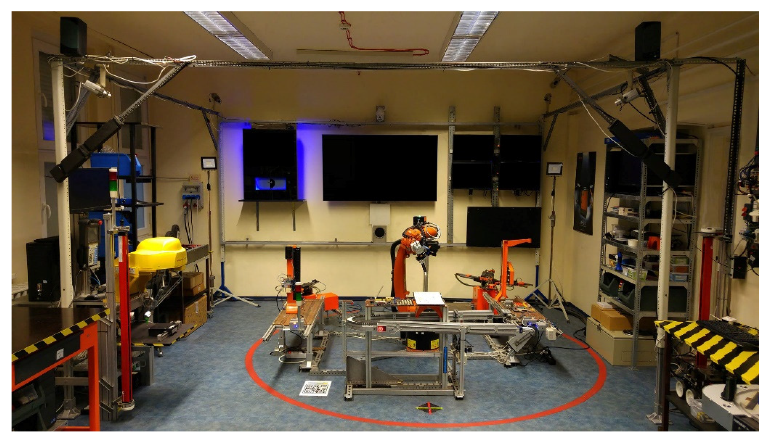
Following these tests, participations are able to evaluate the results, and decide whether they would proceed to integrate these solutions to their existing systems or not. These tests are not carried out in a live environment, so these evaluations may be made safely, and modifications are also possible. The COVID-19 pandemic and the globally present microchip shortage have both made an impact on the laboratory’s work [4]. To continue the previously started research and educational tasks, the laboratory itself had to be put onto a new foundation, meaning that the laboratory seen on Figure 1 had to undergo a complete digitalization and integration into the cyber-physical space. The pandemic has obviously proven the relevance of our efforts to digitalize our research and educational materials. Our new servers alone are unable to serve these needs.
To match the new challenges, a complete digitalization of the establishment had to be done, based on data that is available to us (see Figure 1).
The cyber-physical system, as a technology, is part of Industry 4.0 [5]. Depending on the discipline, there are various definitions of cyber-physical systems [6]. It refers, more broadly, to the complete integration of physical processes. Virtual elements can interact with real-physical objects and track their behavior and movements. Two-way continuous communication is frequently used to accomplish this [7].
A replicant copy of a particular production department is referred to as a “Digital Twin”, and the term has already entered the public domain. Such systems do not necessarily need to communicate with one another to exchange data. A virtual replica offers a foundation for further development because it permits redesign [8].
Digital twin-based systems must also meet sustainability requirements. On the issue of sustainable development, the UN Brundtland Report of 1987, “Our Common Future” [9], called for action that meets the needs of the present without compromising the future generation. It can also be seen as a development concept that involves minimizing available resources [10]. This goal can be achieved through intelligent manufacturing, which requires large amounts of data processing and storage [11]. The digital twins represent a large data set, as they are detailed and extensive replicas of an existing physical manufacturing department [12].
It is important to note that a digital twin is a new approach to production that emerged after 2015 and can be seen as a kind of optimization of Industry 4.0 [13]. The digital twin has a widespread impact on sustainability at an environmental and financial level, as the technology allows processes to be pre-tested before being translated into an actual physical process [14]. In addition, it can also play a role in maintenance, thus increasing the life cycle of a production line or product [15]. It can be used to predict when maintenance should be carried out on a process [16]. The big data sets generated by the digital twin are also advantageous because, when designing, engineers can make decisions based on the data and do not have to approach the problem intuitively [17].
Moreover, with sufficient data, machine learning techniques can facilitate design decision making [18]. One possible near-term application of replicant factories could be manufacturing augmented by artificial intelligence [19]. Big data sets provide the opportunity to train neural networks, thus reducing the generation of scrap parts and rescheduling production [20].
Several other studies have also looked at the digitization of manufacturing. One approach is to increase the flexibility of production lines so that a larger number of individual parts can be produced [21]. Individualization can be achieved by increasing the degree of digitization in manufacturing. In addition to virtual production lines, cloud networks enable faster data sharing and evaluation [22].
According to some, connecting machines to a network is the main focus, but different perspectives’ collection and analysis of sensor data is the most important task [23].
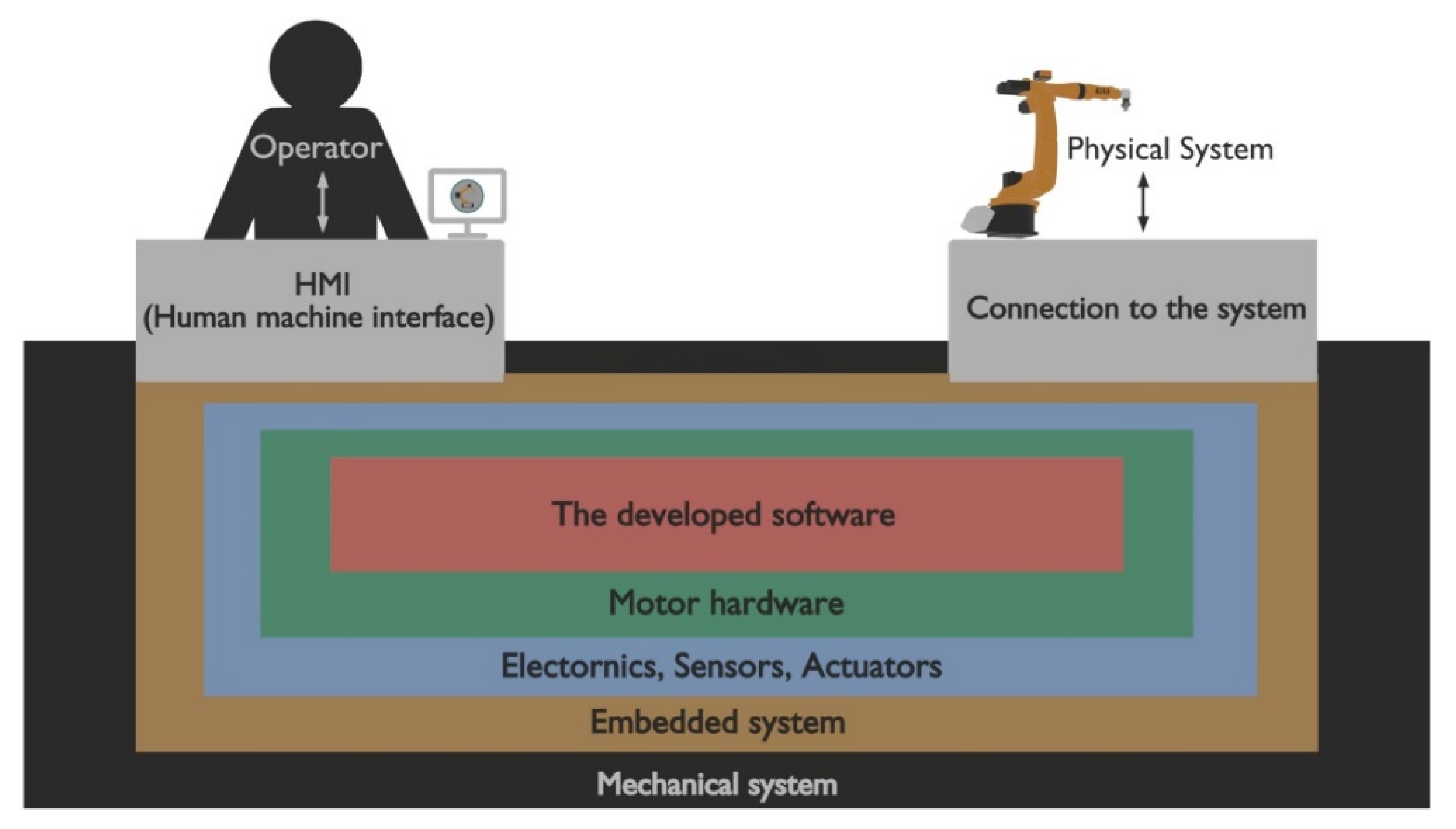
Meanwhile, integrating the laboratory itself into the cyber-physical space is only part of a complex task, as simulations can be categorized into various groups with, each with specific characteristics (see also Figure 2).
Simulations are used widely in different industries as they can aid in avoiding design issues, make complex processes easier to monitor, and allow for the comparison of various control systems and performance thresholds [24]. These opportunities are also important to us because the laboratory was extended by numerous original parts, which might be of elevated importance in view of the entire system. It is extremely important to be able to integrate these into a new environment. Since the laboratory only has a speed of 100 Mbit/s in our case, the applied cyber-physical system cannot communicate with the physical components, and the network dynamics cannot support continuous two-way communication. As a result, the robotics education area was represented virtually.
Virtual-based education has many advantages if the person has access to machines because it eliminates the need to travel far to use a real physical machine. Typically, robots are equipped with workspaces that act as a limitation for the space available. Alternatively, some machine units cannot be approached because of the robot cells built around them [25].
The robot, on the other hand, can be operated to a high degree if there is a precise virtual replica of it [26]. The industry frequently employs VR (virtual reality) technology with trackers to interact with the virtual elements to achieve that [27]. VR technology was not used in this instance. Therefore, it is possible to move around in our virtual space using a keyboard and mouse together. As a result of choosing the keyboard and mouse controlling method over the VR technology, the digital twin will be available to a larger group of students. The fact that there is no physical interaction, and the operators cannot grasp and feel the weight of each element, is one of the major drawbacks of training operators in this manner [28]. Thus, unfortunately, it is indeed possible to create a false sense of security in those who use purely a simulation environment at a high level, without participating in physical instruction [29]. There is a wide range of options available for creating virtual spaces. A 3D Gazebo simulator can be used to develop ROS-based environments and integrate robot navigation [30]. According to one study [31], if the vehicle unit that must be controlled is connected to a network, it would be possible to send commands to the physical vehicle while also monitoring it via IP cameras. Digital technology also enables the creation of testing environments for the automotive industry [32]. Additionally, beneficial to education, digital labs allow for the informal practice of complex tasks in a virtual environment [33]. The main concern with this kind of teaching strategy is its effectiveness. There are various methods for evaluating this [34].
The virtual environment we created differs from comparable educational initiatives in several ways. One of the primary differences is that industrial robots with various custom hardware enhancements are present in the virtual environment (e.g., custom robot cell, industrial gripper, conveyor belt). Additionally, the procedure can be followed through virtual cameras, the area is completely accessible, and extra models can be added and removed as needed. Alternately, the program can be streamed using particular VOIP services, allowing for “online” training [35].
2. D CAD Modelling of the CPS Lab Units
The availability and optimization of 3D models is a cornerstone of placing the laboratory into a cyber-physical system. In simple terms, as optimizing 3D models require a smaller file size, geometric (polygon) and texture changes are used to reduce the size [36]. The 3D model’s geometry is the mesh itself, and the texture is the surface covering.
Mesh decimation [37] is a type of model optimization that reduces the number of polygons in a model, makes the file smaller, and requires less GPU-based rendering computation [38].
Students would have the chance to program robots “offline” during the pandemic thanks to the facility’s comprehensive 3D modeling. Due to the complexity of the robot handling the Teach Pendant, robot units like the KUKA KR5 require physical presence during instruction. However, the students can freely learn robot control if it is integrated into the virtual environment. Additionally, due to the lab’s size, no more than 8 students may attend the training, but a software that can be downloaded to one’s person PC has no usage limitations.
To this end, a large-scale data collection and overview of our industrial tools has started in the Cyber-Physical and Intelligent Robot Systems Laboratory. By collecting the parameters of the existing machines, we are able to put them into the virtual cyber space for simulation and controlling purposes [39]. For the robots, this includes various measurements and collection of programs. Using these, we are able to gain understanding of their workings and behavior, which is crucial for integrating them into the virtual space [40]. The different parameters include kinematic structure, work area, used coordinate-system, and maximum load, which have all been collected, categorized, and recorded. Using this information, we could start designing the needed 3D models, with a detail level that takes the available processing performance into account. In the Cyber-Physical and Intelligent Robot Systems Laboratory numerous research projects are underway, which includes physical cell-based systems as well. During 3D modelling, every robot present in the laboratory was modelled. Since our CUDA processing capacity is limited, these machines were all modelled separately [41]. For creation of these models, the open-source solution, Blender was chosen, which is widely used in various industries as well [42].
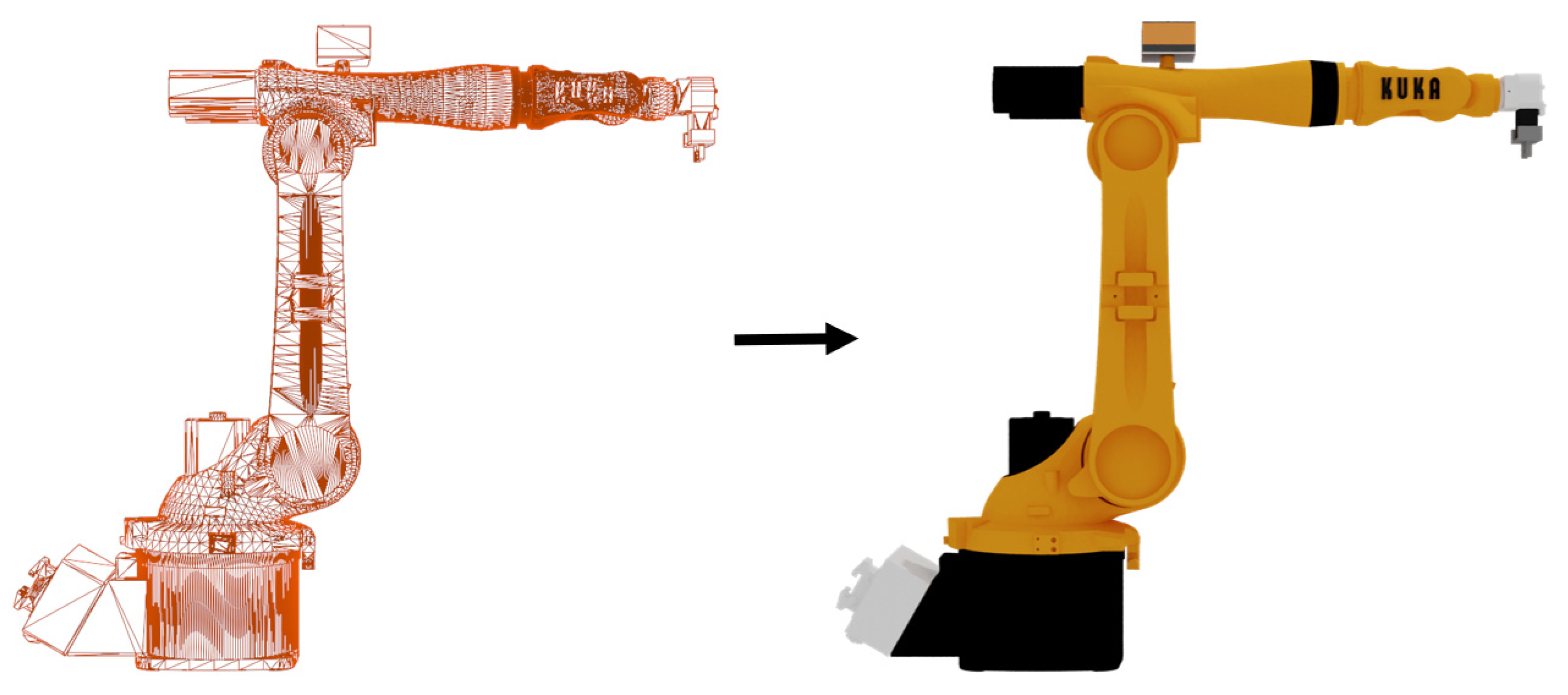
Due to limited resources, the models themselves were unsuitable to be integrated into one simulation environment all at once. This is mainly caused by the fact that the number of models and the resolution of their textures required increase computational capacity. To this end, the 3D models had to be optimized to decrease the number of polygons used (shown in Figure 3). As for the textures, we have decided to use simple RGB color materials instead of complex bitmaps [43].
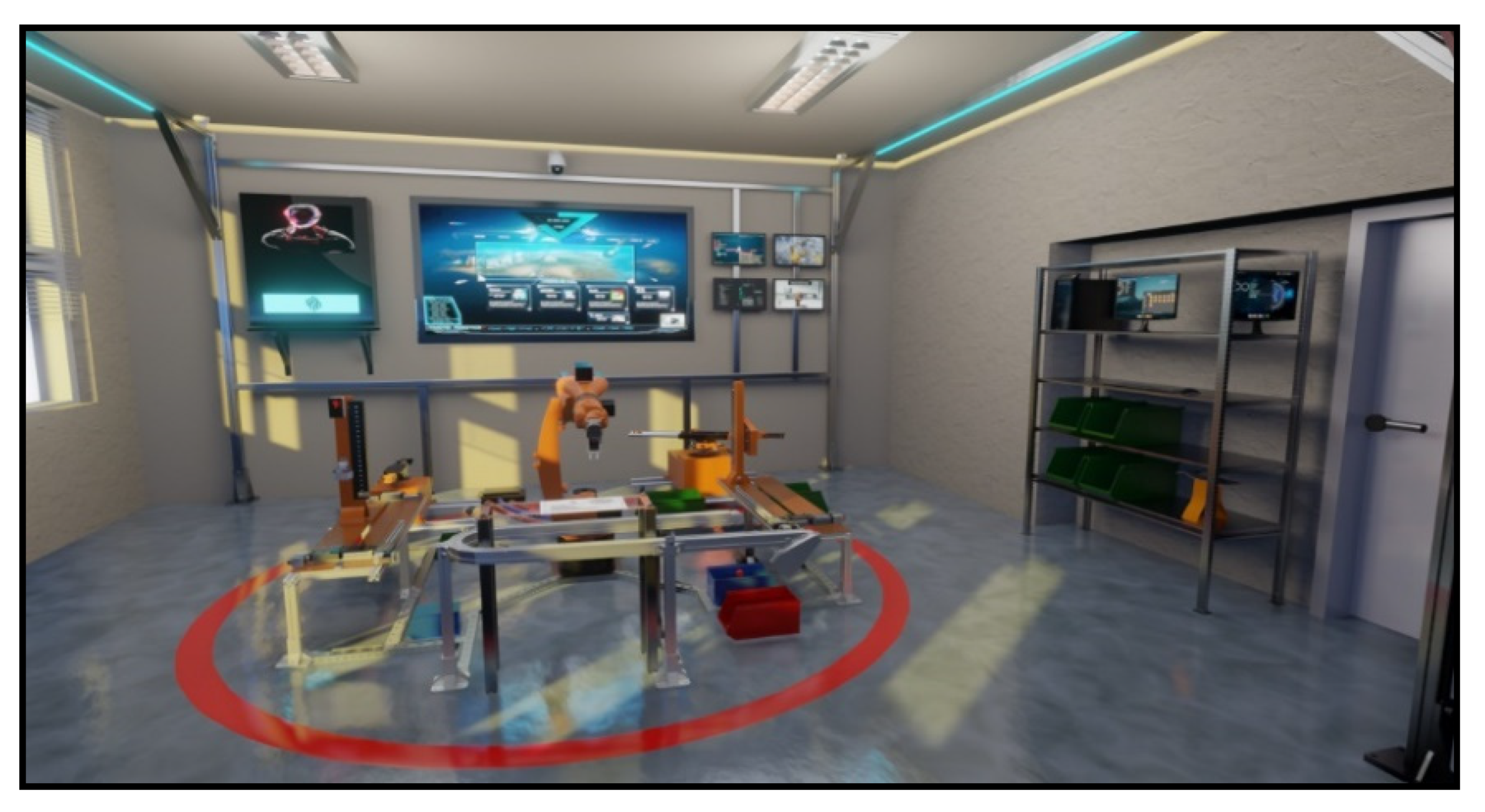
The Covid-19 restrictions harmed education in the engineering area. The results of an analysis from 11 engineering faculties show that accessing technology was students’ biggest problem during online activities [44]. Tracking the current learning status during online education is more effective with simulation software [45]. Taking this into consideration while creating the digital twin of KUKA KR5, a decision was made: even if the software focuses on the industrial robot, it is necessary to create the 3D model of the robot laboratory (shown in Figure 4). This allows integrated robots to control tasks from the physical world.
The robot cell played a significant role, as it is part of a completely original internal development. Thus, we had to take care that the expandability of the real cell is preserved duding modelling [46].
3D models which are important for the implementation of the task:
- KUKA KR5 robot arm;
- Gripper and tool item of the robot;
- Table with geometric symbols;
- Conveyor platform;
- Left and right platforms;
- Teach Pendant.
3. Simulation Frame and Re-Creation of HMI
As previously mentioned, there is no communication channel between the virtual objects and the physical components in our case. The physically constructed KUKA KR5 robot unit cannot be programmed with the virtually written robot program.
To make the teaching process simpler, only a small portion of the simulation space was created. This includes HMI management [47] and robot programming inside the robot cell. For this reason, it was necessary to choose a program for the design that could serve the needs described above.
The Unreal Engine 4 is a powerful 3D creation tool used in game development, architecture, automotive visualization, and movie industries [48]. UE4 offers an opportunity to use visual scripting via a blueprint system, which allows the developer to create and use variables, functions, and events without coding [49].
While Blender serves the purpose of creating the models perfectly, using Unreal Engine 4 to make a simulation with the created models offers an opportunity to a real life like robot control method.
During the project, a computer of the following specifications was used:
- CPU: AMD Ryzen 5 3600X AM4 (6 core, 12 threads, 3.8 Ghz–4.4 Ghz;
- VGA: Nvidia GeForce RTX 2060 SUPER;
- RAM: 16 GB DDR4 3200 Mhz;
- SSD Samsung 860 QVO 1TB [50].
To handle and import the models, and to run Unreal Engine 4, the PC detailed above was available. The packaged software however works on machines weaker than this as well. It is extremely important that the completed project is usable on weaker computers as well, and that the end-user version published is as small as possible.
Since different software use different scaling, it is advised to pay attention to these conversions while exporting from Blender to Unreal Engine [51].
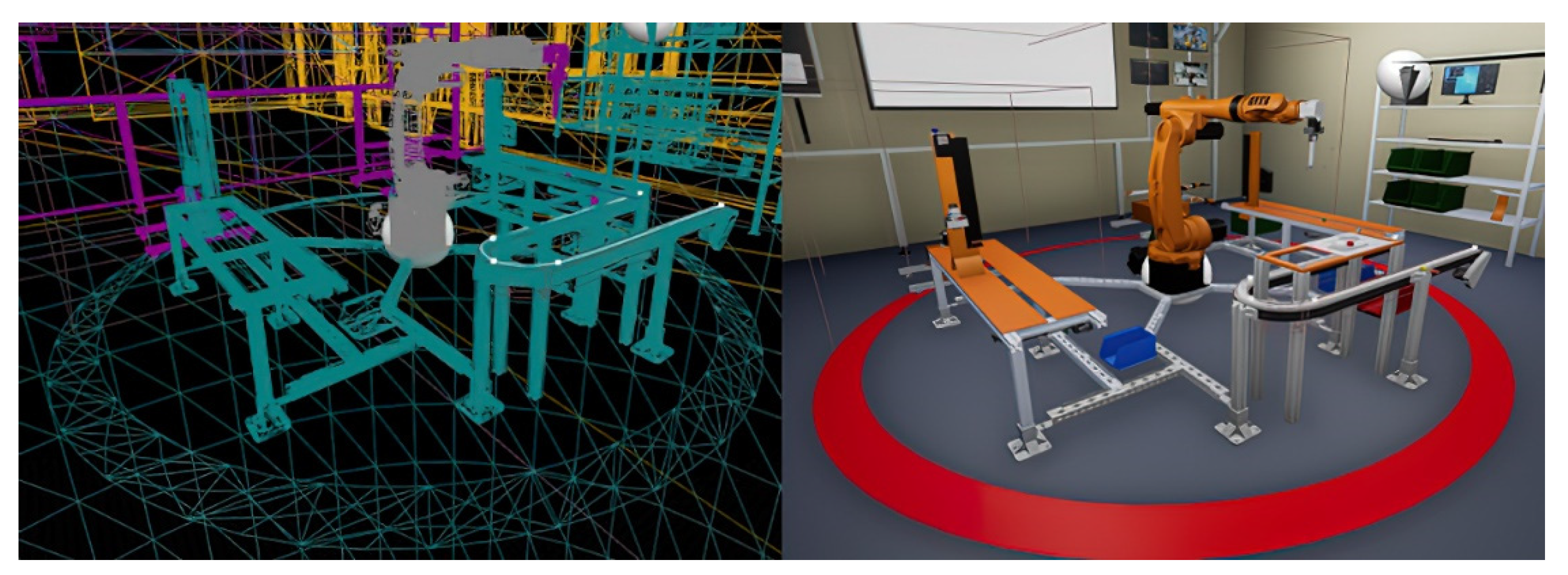
Blender measures lengths in meters, while Unreal Engine uses centimeters as its basic unit. Before exporting as FBX, it is recommended to do this scaling in Blender, by setting the Scene Unit Length to centimeters, and multiplying all dimensions of the existing models by 100. By using “Apply scale” in Blender, we will be able to see the appropriate scale in Unreal Engine as well. Adding a UV map to the models is absolutely necessary, otherwise models will appear completely black, because UV channels are responsible for lighting information. KUKA KR5 work area in LIT and Wire views shown in Figure 5.
During export, one must also take care that Unreal Engine uses a left-handed coordinate system, while Blender uses a right-handed coordinate system. To avoid potential issues and error messages, it is recommended to set Smoothing option from “Normals only” to “Face.”
In Unreal Engine 4, at import settings, the setting “Normal Import Method” “Import Normals” must be changed to “Import Normals and Tangents”, otherwise the quality of models will be inadequate.
For the KUKA KR5′s model, a simple Bone Chain was made in Blender. Due to this, this model had to imported as a skeletal mesh.
In Unreal Engine 4 there is a possibility to add Collision to our modes, which would be exactly fitting to our models. However, this can have a negative effect on performance, and as such, “Box Simplified Collision” was used instead. Where one box was not enough, multiple boxes were used to create a simple collision mesh. So far, this solution seems to be adequate for our goals. Unreal Engine 4 offers multiple pre-created templates when a project is created. The FPS template provides the first-person view with a basic spatial navigation. The FPS template contains a controllable character with a first-person view. This point of view helps in a way, that during programming, the KUKA KR5 robot the robot itself is in focus, because the body of the first-person character is not visible. This enables virtual navigation using the internal view. The term refers to the camera’s point of view.
After removing the parts that are not necessary for the simulation and modifying the joint rotations of the arm to place a remote controller in the hand, the first-person view can be used as the main persona in the cyber space.
This template contains navigation by moving using the W, A, S, D keys, and rotation by mouse.
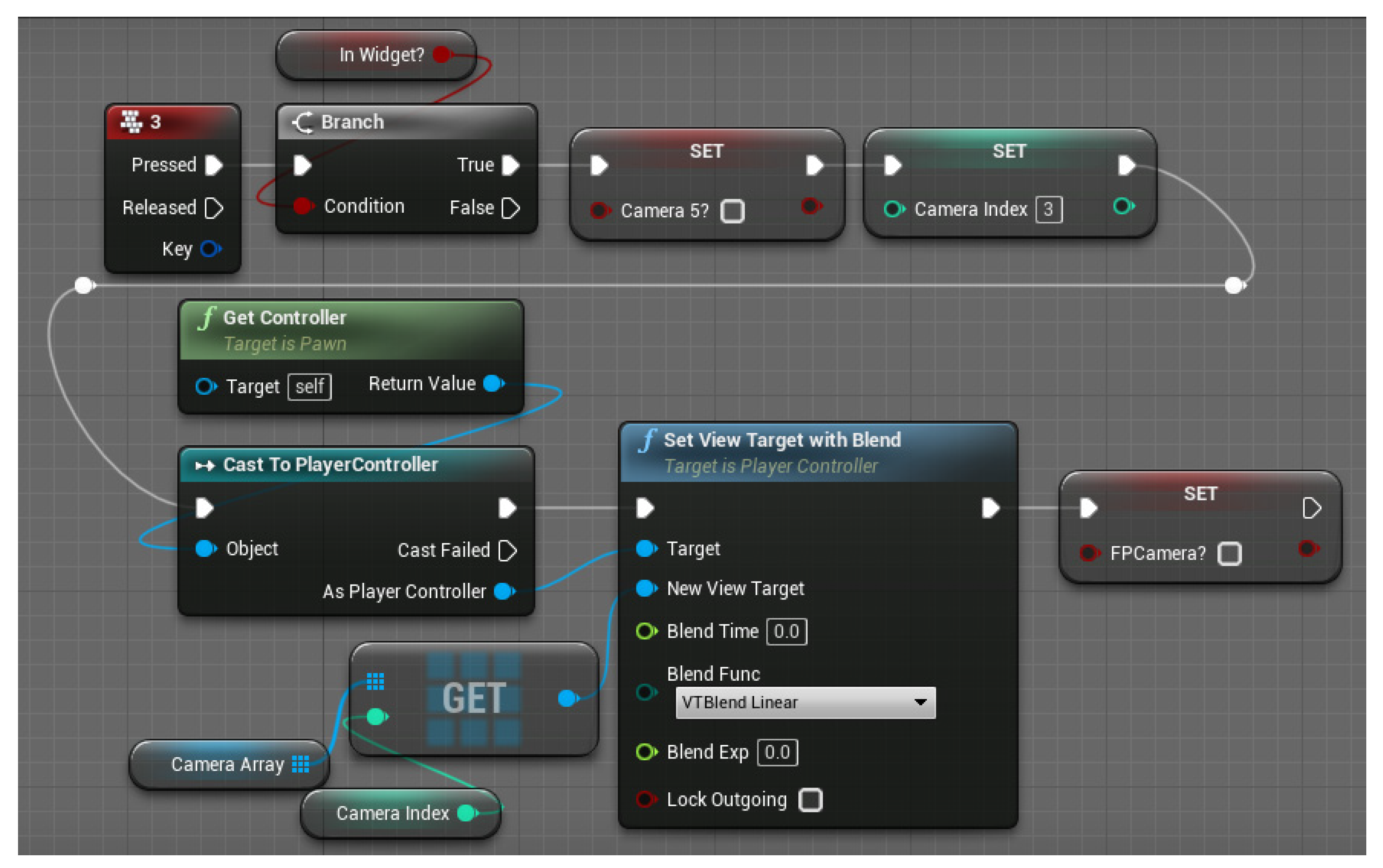
In order to be able to observe the KUKA KR5, 5 different cameras were placed, which have been assigned keyboard shortcuts from 1 to 5, while pressing 0 switches back to the first-person camera. Figure 6 shows the basis of the programming of the switching meth-od between cameras.
Using these cameras, and the camera connected to the first-person view, there is a possibility to zoom in using the scroll wheel. The camera behind the KR5 is able to be rotated on two axes.
Figure 6 displays the blueprints of switching to only one camera. When one of but-tons from 1 to 5 on the keyboard are pressed the program checks if the KUKA KR5 HMI is open. If so, the Camera5 bool and Camera index integer variables will have a new value. The Camera5 bool is necessary because the rotation on two axes is only possible with this fifth camera and the value of this bool variable is checked when the user wants to use the rotation function. The second part of the blueprint displays the selected camera on the user’s monitor with a function called “Set View Target with Blend”.
After the cameras were placed, the next task was to recreate the KR5′s HMI.
The human–machine interface, or HMI, is a critical component in the control of any robot unit as it allows the user to interact with the robot. Each HMI is unique and can be managed using different rules. There are some similarities, such as emergency stop and Deadman switch.
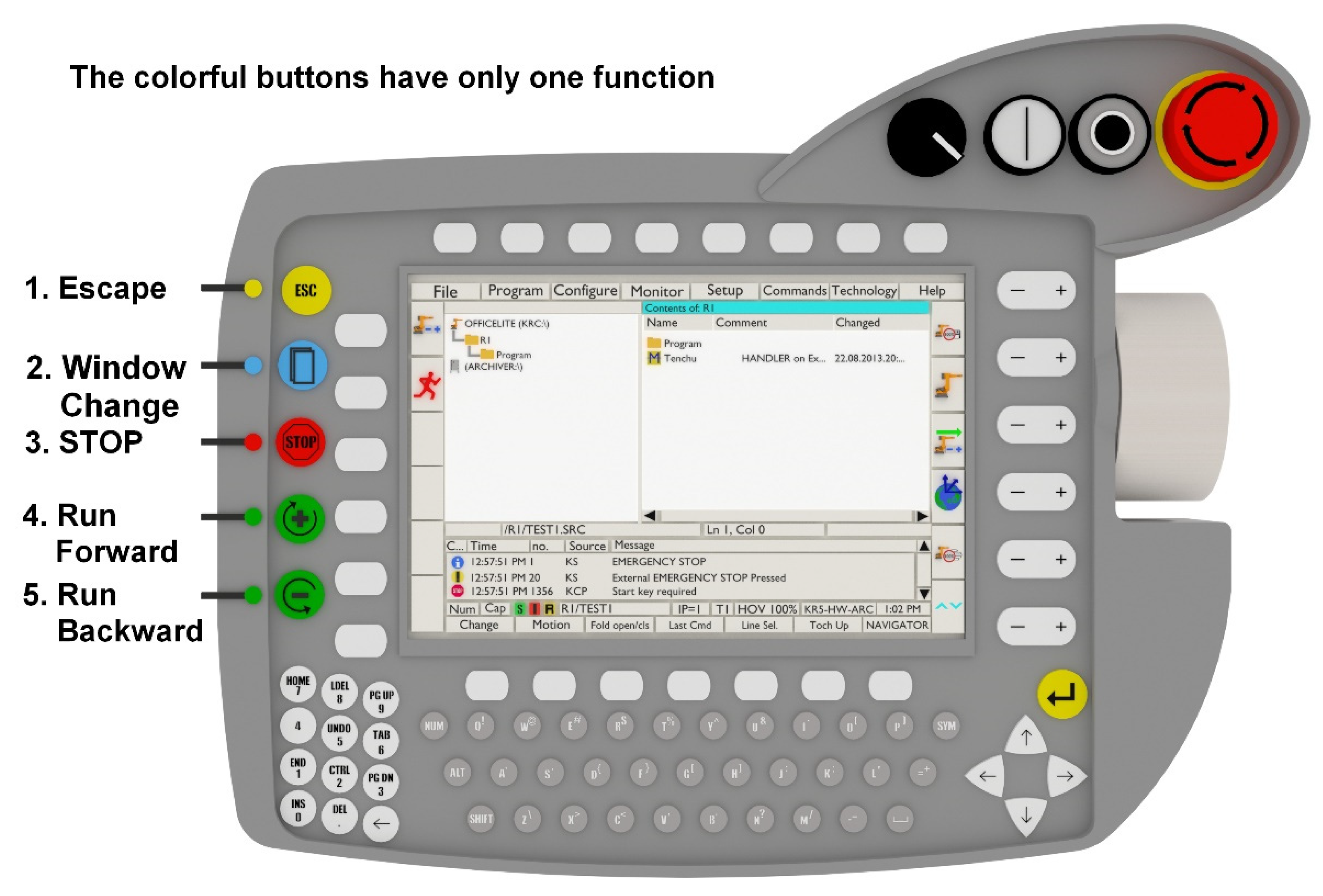
In the case of the KUKA KR5 robot, the HMI has been modeled, which can be seen in Figure 7.
The HMI has color buttons and is ergonomically designed. These buttons are only used for a specific function, such as the Esc key, windows changer, forward–backward run, and emergency stop. A keyboard is included in addition to these. The blank buttons are empty during the process and serve no purpose.
As we can assign features behind the 3D model elements, we are able to create a virtual copy of the 3D model itself as the physical Teach Pendant corresponds to these functions.
The Visual Scripting of Unreal Engine 4 allows the creation of custom events, which are invaluable during the making blueprints. These custom events help with keeping the program easy to overview by allowing a longer program to be split up into smaller parts. Moreover, other blueprints can also call these program parts when casted appropriately. Similarly, to functions and macros, inputs can also be added. However, custom events do not have return nodes or completed outputs. Instead, another event may be called at any time. The advantage of events compared to functions and macros is that Delays, Timers, and Timeline nodes can be freely used.
The Unreal Engine Graphics UI Designer (UMG) is the tool for creating user interface elements. The Widget Blueprints are the cores of UMG, which has a series of pre-made functions. These functions are related to UI buttons, text, and images. Therefore, using the UMG for designing the virtual Teach Pendant is advantageous. The Widget Blueprint has two tabs. On the Designer Tab, various buttons, text, and images can be placed and customized, while the Construction Tab can be used to add functionality for the placed components.
The Designer Tab gives the possibility to adjust initial visibility of individual items. These changes are only reflected once the simulation is started: while assembling the interface itself, every element is visible, which makes Designer Tab difficult to navigate after a while. Figure 8 shows the developer appearance of KUKA KR5 virtual HMI, but to hide or show some elements when one of the UI buttons are pressed using the other tab of Widget Blueprint is inevitable.
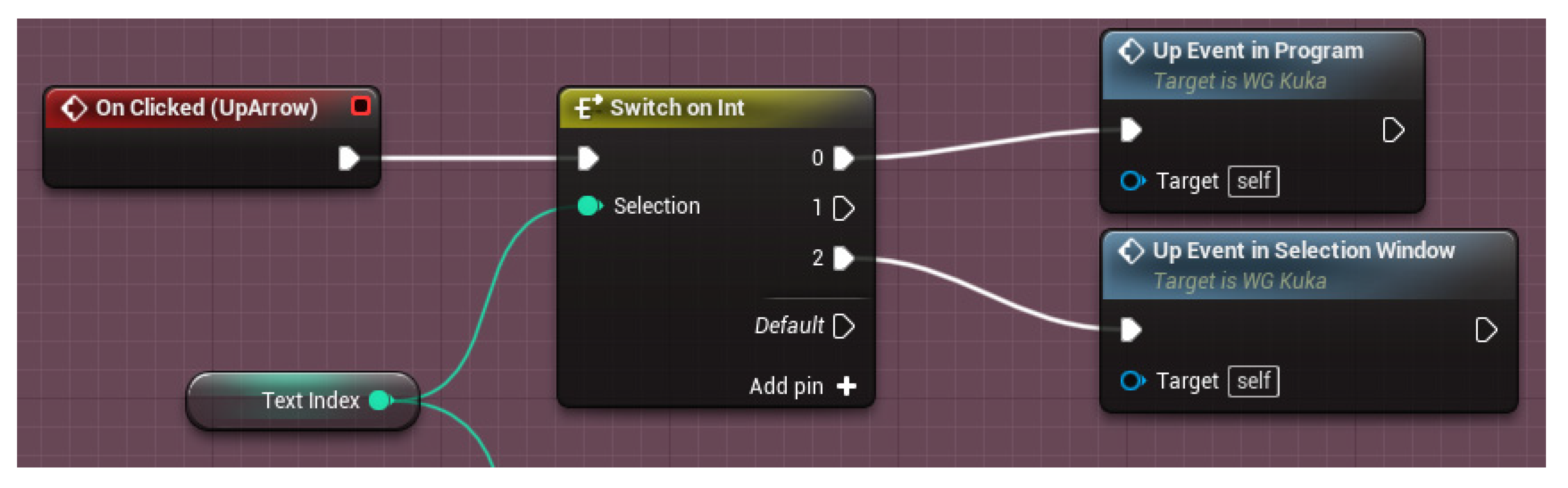
The Construction Tab contains a few basic Events, like the Event Construct, which runs once when the Widget is created, or the Event Tick, which runs the given command on every tick. “On Clicked” events may also be added, which run after a button is pressed. Custom events may also be added. The listed tools can be used to add the functions found on the physical Teach Pendant. The buttons of Teach Pendant can have more functionality, depending on what task the user is performing. To avoid bugs, after pressing certain buttons, which manage starting new tasks, the value of Text index integer variable is changed. This integer variable with a switch statement is called after pressing any button on the user interface and starting new events. Figure 9 shows an example for the switch on int part. When the user opens a KUKA KR5 program then the Text index integer has a value of 0, but when the user is navigating between programs, the value of the Text index integer is 2. When the Up Arrow button on the user interface is pressed, an “Up Event in Program” or an “Up Event in Selection Window” custom event is called depending on the value of Text integer. These custom events are responsible for navigating between different lines in a program or between different programs in the selection window.
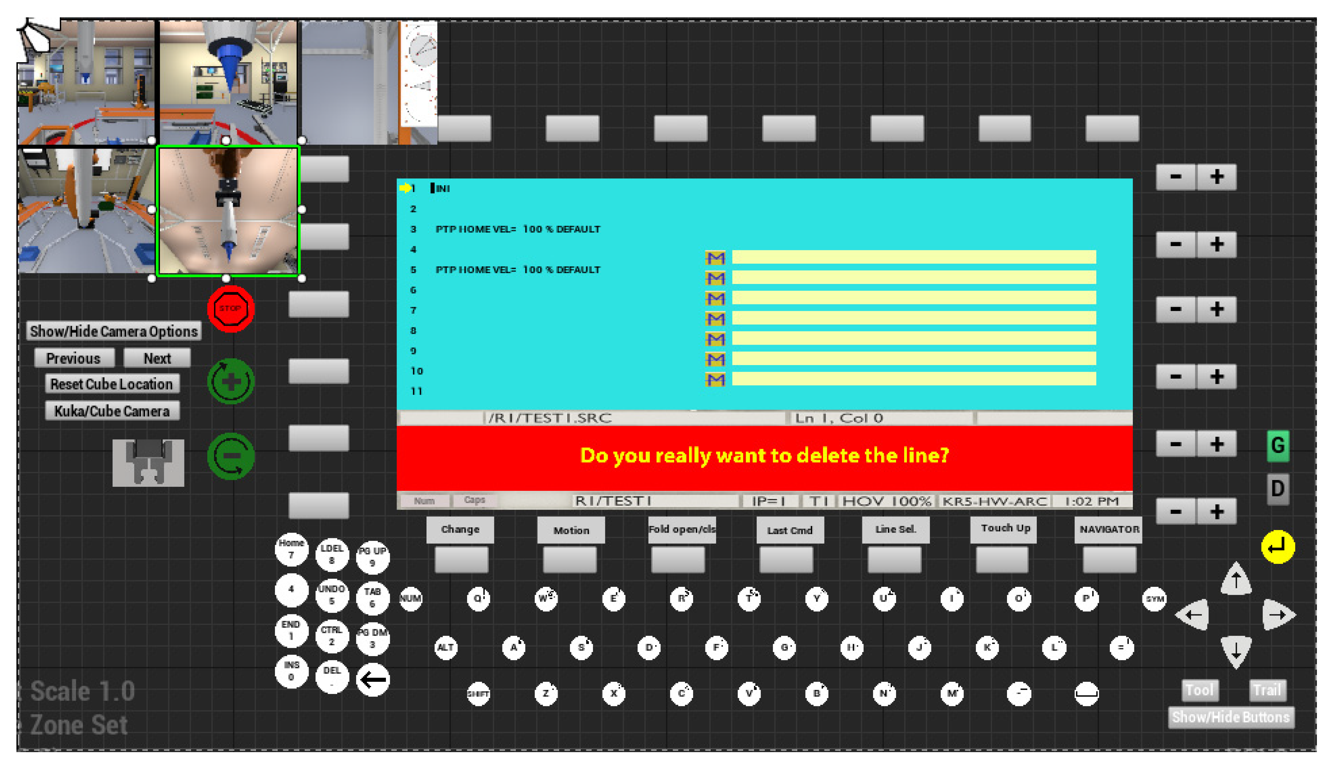
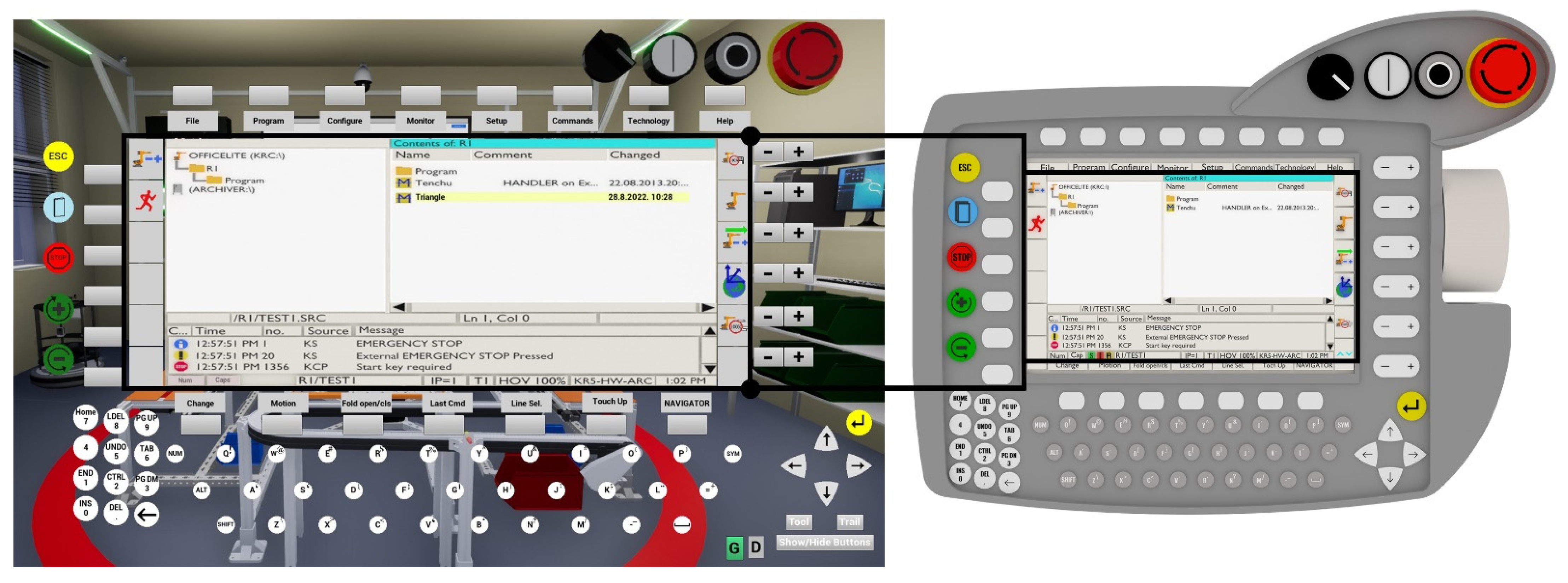
The clarity of the virtual robot control is also helped by “simulation only” functions, such as hiding the unnecessary buttons using “Show/Hide Buttons”. The cameras placed around the TCP replace the present of an assistant observer. After the initial visibility settings, the user interface of the digital twin becomes easy to compare to the teach pendant, which is the core of the HMI in the real world. The UI (user interface) in the digital twin has the same role as the teach pendant in the physical world: it contains the functions necessary to control the robot and to create programs for it (shown in Figure 10).
The Construction Tab is not limited to functions and events that are linked to UI elements. It allows the developers to add other nodes and functions, which are related to the virtual space. The created programs for the physical KUKA KR5 are stored in the Teach Pendant. Storing and saving data related to the virtual KUKA KR5 is programmed in the Construction Tab.
While Unreal Engine 4 does not allow the creation of two-dimensional arrays, any variable can be set to be an array type. Combining this with a Structure, which contains the name of the KUKA Program, date of creation, rows, and variables relevant to the movement.
Adding the save function was achieved by implementing a method known from video games. Using the SaveGame Blueprint Class, two variables need to be created: an integer, which contains the index of last created program, and a Program Structure Array. The built-in functions of Unreal Engine 4 are responsible for creating files within a project, so it is enough to focus on the Save and Load events within the Widget Blueprint. When creating the widget, it first checks whether a save file exists already. If so, it loads the data into the ProgramIndex and into the ProgramStructArray variables, and during saving, the values of the widget variables are saved into the variables of the SaveGame blueprint.
Compared to a complex program, a relatively small amount of data needs to be stored, which does not put too much of a load on the computer. This gives an opportunity to call the save event multiple times to avoid loss of data. When the user creates a new program, a new element is added to the ProgramStructureArray within the Widget, including the name, date of creation, and the first five predefined rows with two PTP movement types, both containing the Home rotation of the axes. Then, “SaveProgramEvent” is called. After adding rows, this event is always called, ensuring that every change is saved immediately.
4. KUKA KR5 Robot Unit Re-Creation and Control
Previously the creation and structure of the HMI was shown in detail, however, movement of the KUKA KR5 requires forward kinematics–inverse kinematics as well.
Forward and Inverse kinematics are extremely important in our case, because these guarantee that we know the position of the object at any given time. Furthermore, the base coordinates of the TCP (Tool Center Point) also become known, meaning that based on angle data of the axes, we can derive the TCP’s position in the three-dimensional space.
Forward (direct) kinematics gives us information about the TCP’s position based on the current angle of the axes. For this, knowledge of the KUKA KR5’s physical parameters, such as number of axes, axis limits, work area, and physical size, are required.
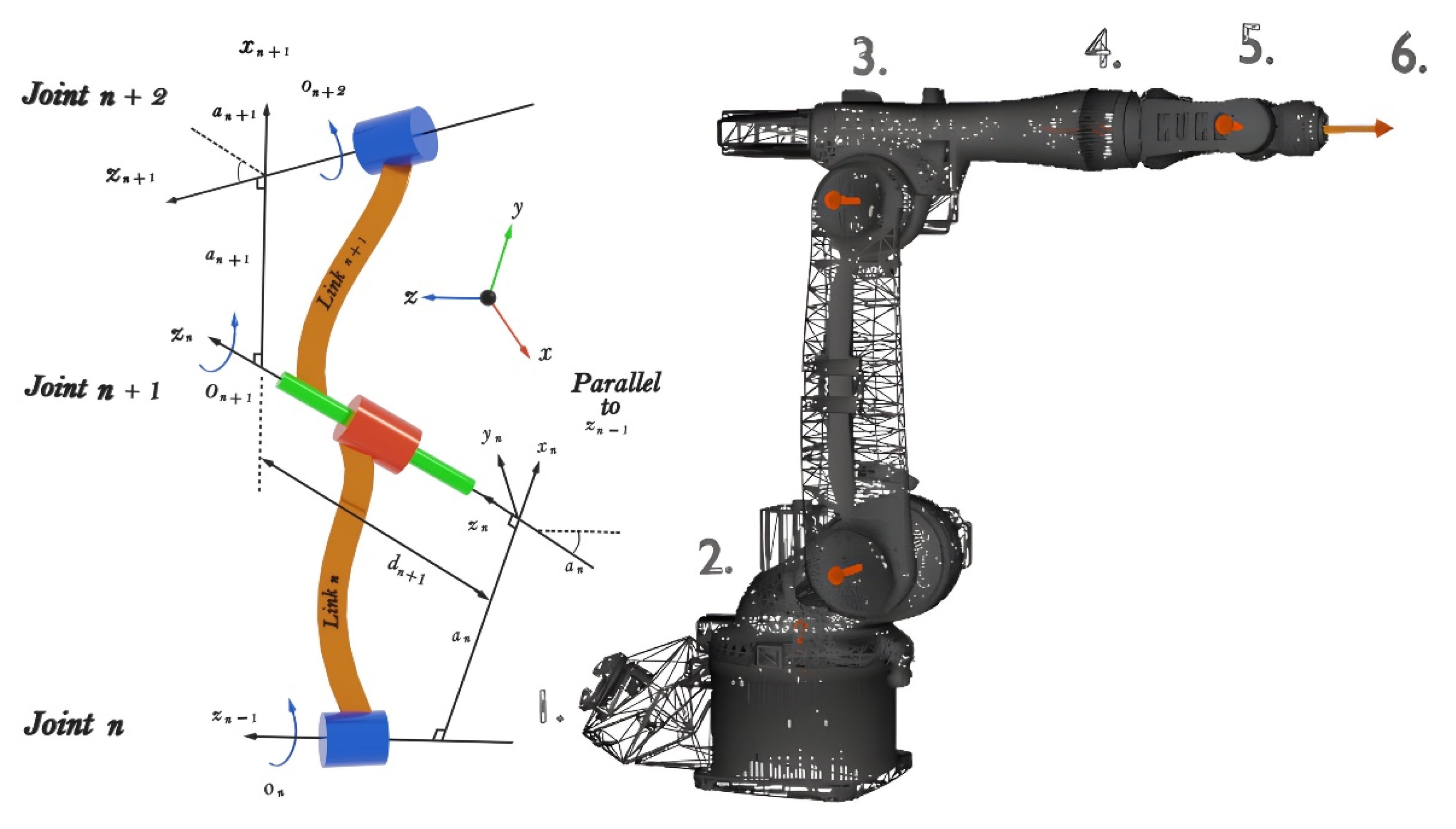
Direct kinematics problems may be solved by using the Denavit–Hartenberg (DH) matrix. The matrix itself is a simple link-joint description method, usable with any robot arm configuration, independent of complexity. Every joint is defined iteratively based on a transformation from the previous joint.
Let us select a joint with the name n. Following this, both n, and n + 1 joint get a local reference frame. The local frame of reference is described by the axis z, which can be translational or rotational (shown in Figure 11).
Inverse kinematics, unlike direct kinematics, is a method that requires more complex calculation methods. In this case, the position is known, and we are looking for the appropriate joint parameters [53].
It is important to note that the robot’s geometric model describes its spatial position. The kinematics model meanwhile describes problems regarding velocities. For this, the Jacobi-matrix must be used, where joint speeds and end-effector speeds are differentiated.
Joint speeds are:
- -
- Rotational joint (angular velocity around a rotational axis)
- -
- Translational joint (linear velocity around the axis of movement)
End-Effector speeds are:
- -
- Angular velocities around x, y, z
- -
While describing these connections, one must start from a direct geometrical problem. Position and orientation of the end-effector:
A D-H makes the elements of the last row’s elements 1–3 [54].
where:
- m—Degrees of Freedom of the robot
- n—Dimension of robot’s work area
- J—Jacobi matrix of the robot’s Jacobi matrix
The inverse of the Jacobi matrix is required to solve the problem [54]:
Correlation between end effector and joint acceleration [54]:
5. KUKA KR5 Robot Control in Cyber Space
The buttons on the Widget Blueprint are pressed by the user using the mouse cursor. Obviously, multiple buttons cannot be pressed simultaneously. Therefore, the Deadman Switch is replaced by a keyboard key. In Unreal Engine 4, there are certain events called by the press of a keyboard button. Detection of middle position, normally found in Deadman Switch, is not possible with a keyboard. Therefore, this function has been omitted from the simulation environment.
There are two methods to move the KUKA KR5: Using free kinematics by rotating the joints one by one or by moving the TCP into the desired position with inverse kinematics.
To modify the joints of a Skeletal Mesh in Unreal Engine, an animation blueprint must be created. This is a special blueprint which can be used to control the skeletal mesh linked to it. In this case, the animation blueprint is attached to the skeletal mesh of KUKA KR5. The Event Graph of Animation Blueprint contains a special event called “Event Blueprint Update Animation” which runs in every frame. Therefore, from the user’s perspective, it happens instantly. Using the AnimGraph, the control rig is also available, which is a node-based rigging system capable of creating the necessary inverse kinematics virtually. Figure 12 shows the AnimGraph, which can communicate with the control rig. The input values of the control rig are read by the Animation Blueprint in every frame. The Output pose is basically the appearance of the KUKA KR5 with the current axis rotations.
When pressing one of buttons responsible for movement, the “Set Timer by Event” node causes the Custom Event to run, repeatedly, until we release the button, which calls the “Clear and Invalidate Timer by Handle” function. The time input is a numerical value in seconds, which shows us the time spent between two executions. Changing this value can be used to make the robot move faster [55].
The custom event that belongs to the free kinematics changes the value of “Axis Rotations”, which is an 1D float array created in the KUKA KR5’s blueprint. When the buttons controlling the movement are pressed, an integer’s value instantly changes to an integer between 0 and 5, and a float variable gets a −1 or +1 value, which is responsible for the direction of rotating.
The FK event changes the value of one of the elements of “Axis Rotations” float 1D array by adding the multiplication of a pre-defined “FKAdding Value” variable and with −1 or +1 depending on the direction of rotation. By using the “Clamp float” node, the rotation can be confined between join limits.
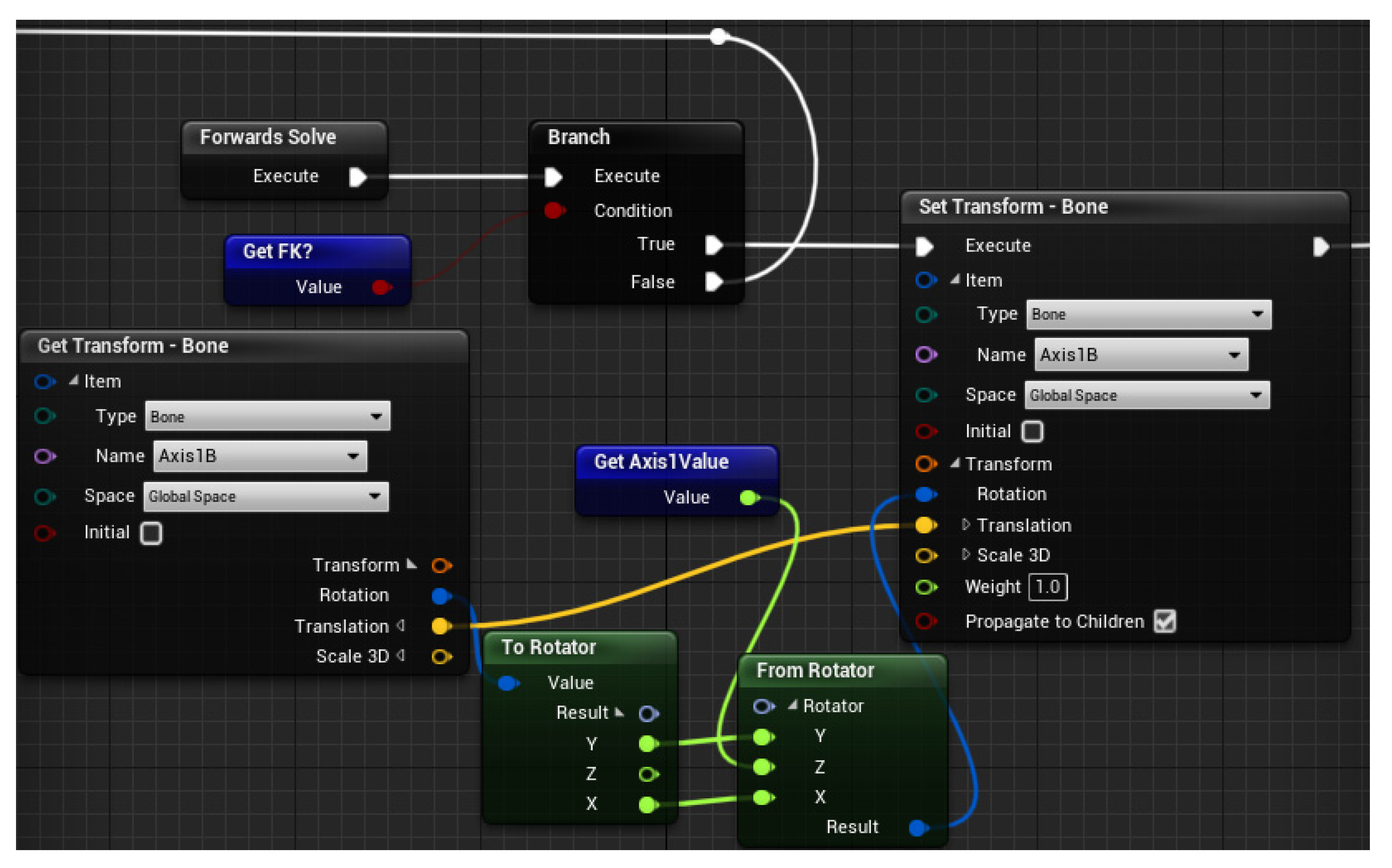
The value of “Axis Rotations” array found in the KUKA KR5′S blueprint is changed through the Animating Blueprint’s AnimGraph, which are sent to the Control Rig, where the current value of “Bone” rotation is overwritten by the new value. Figure 13 shows a part of the control rig, when the Axis 1 of KUKA KR5 is rotating. First it checks if currently the user is controlling in the joints coordinate system. If so, then the program with the “Set Transform—Bone” will change the Z rotation, while the X and Y stay constant. The new value of Z rotation is given by the AnimGraph as an input for control rig.
To change the TCP world coordinates, inverse kinematics is required, which is created in the Control Rig. In Unreal Engine 4, since version 4.26 the full-body IK node is present, based on Jacobian Pseudoinverse Damped Least Squares. The full-body IK gives numerous opportunities to change settings during runtime and has other options as well. Multiple controls can be created, which can be moved and rotated using variables. One of these controls can be used as the FBIK effector [56].
The position of the IK control gets to the Control Rig via AnimGraphs. In the case of joints A1, A2, A3, overwriting the FBIK with limiting the rotation to only one axis is enough. However, in the case of A4, A5, A6, an “Aim Math” node is required, along with helper controls, to keep the desired orientation.
For controlling the TCP in the world coordinate system, a helper actor must be added, which is invisible to the user. Pressing the movement buttons of the user interface, the IK actor’s position changes, and this position is given to the IK Control found in the Control Rig. Changing the position works similarly to FK movement, however in this case, a custom event tied to a timer adds or subtracts a given value to one of the coordinates of the IK actor.
After the controlling of KUKA KR5 is finished, the previously created program can be expanded with the HMI. Every time the motion button is pressed, a text appears in the next row that contains the type of movement and status of the gripper (open/closed). As this happens, temporary variables store the program line, joint rotations, and the position of the IK actor. Pressing CMD OK, these temporary values are added to the chosen element of the ProgramStructArray, then SaveEvent is executed. Before pressing CMD OK, it is possible to choose the movement type, which is stored in an ENUM variable. This is relevant while playing back the program, however, choosing the CIRC Motion option makes it necessary to add the coordinates of Aux and End points. To achieve easier playback, after every addition, regardless of movement type, joint rotation values and TCP vector coordinates are saved. Aux and End vectors are added for LIN and PTP movements as well, despite not using them—this is mostly to keep index values in the array consistent [57] (shown in Figure 14).
To run the program, the G button must be pressed on the keyboard to start the “Play Program” Custom Event, which has an integer input that is the initial index of elements related to motion arrays. This value is sent to the “Motion Index” integer variable inside the KUKA KR5′s blueprint. “Switch on Enum” node calls the event related to the motion type. “FKMovement” custom event starts in case of PTP motion, “Simple Movement” custom event is called in case of LIN, and “Circular Movement” in case of CIRC motion type. At the end of each movement type, an “EndOfMotion” Custom Event is called, which first opens or closes the gripper with an event, if necessary. After the Gripper Event, if the value of “Motion Index” is not equal with the “length of matrixes assigned to the movement” −1, the “Play Program” custom event is called again with an index value that is increased by one. This is repeated until the program is finished.
The basis of the movements is given by the combination of a timeline and a lerp. In the timeline, with a float track two points are added: at 0 s a 0 value and at 1 s a 1 value. The Lerp node has three inputs: A, B, Alpha. In case of Alpha = 0, the output gives back 100% of value A, in case of Alpha = 1, the output gives 100% of value B. Between 0 and 1, a linear combination of A and B is returned. The value of alpha is provided by the timeline’s float track, which increases from 0 to 1 in one second.
To avoid the movement happening within a single second, changing the value of Play Rate is necessary. In case of PTP and CIRC motion type this value depends on the rotation angle, while in case of Lin movement it depends on the distance between the start and end points.
During PTP movement, 6 custom events are called with their timelines and lerps. To the A value of the lerps, the KR5′s rotational values are sent, meanwhile to the B value, the rotation values saved in the Program Structure are sent. This makes it so that all joints start rotating at the same time, and when every timeline is done, the “EndOfMotion” Custom Event is called.
In case of LIN movements, the lerp uses vector coordinates. The moment the movement starts, the IK actor’s position is read, which then sent to the lerp’s A input, meanwhile the IK vector array’s value is sent to the B input from the Program Structure.
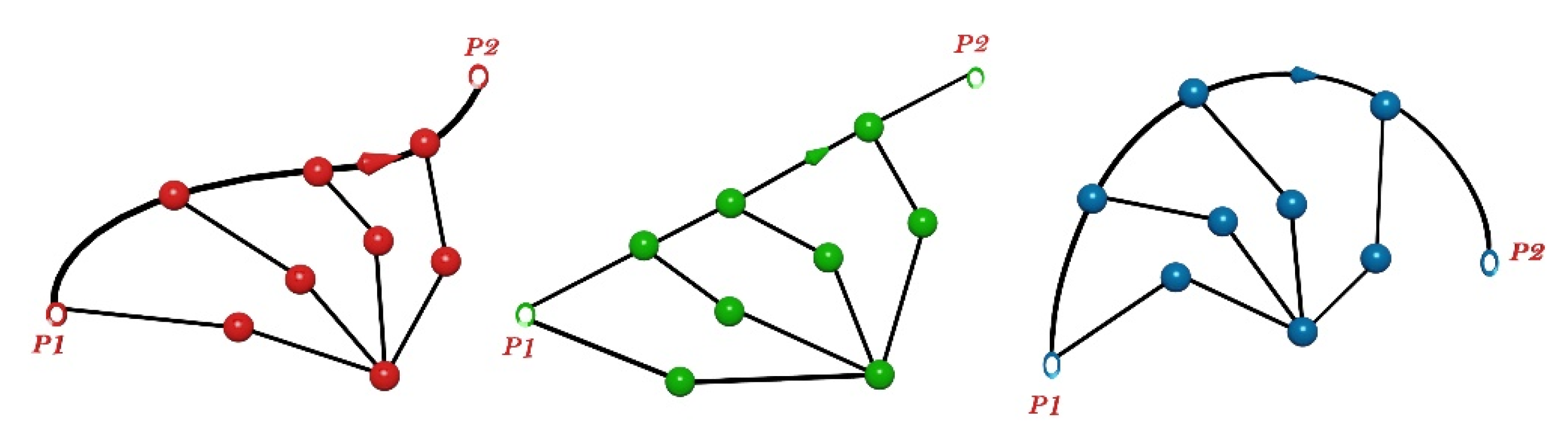
In the case of CIRC movement, the origin of the circle has to be defined by the Start, Aux and End points.
Supposing that a, b, c letters represent the Start, Aux, and End points. P1 is the [ab] line’s half point, P2 is the [bc] line’s half point, d is the origin of the circle. Multiplying the vectors that point from b to P1 and P2, we get a vector that is perpendicular to the plane, and is defined by points a, b, c [58].
O1 and O2 vectors point from P1 and P2 to the origin of the circle, and are described as follows:
Introducing p and q:
Then the origin of the circle is:
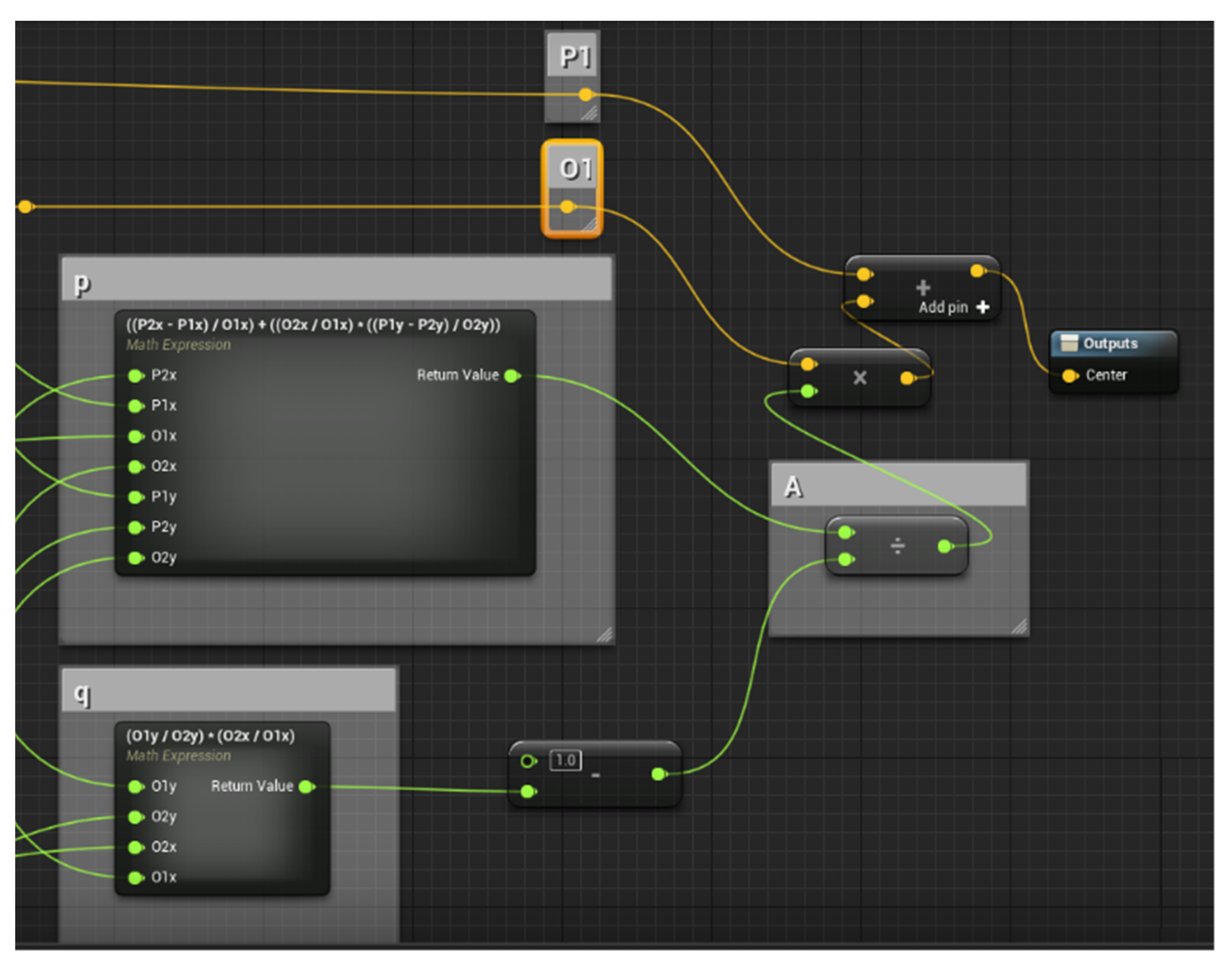
These equations can be entered into Unreal Engine 4 by using a Math Expression Node. See also Figure 15.
After calculating the circle’s origin, we need to calculate three angular values:
Movement along the circular path happens using a rotation. From the origin of the circle, a vector pointing to the start location is rotated by using a vector perpendicular to the circle’s plane as a rotational axis. Let us say this vector is
Assuming that , then otherwise will be the angle of rotation.
Rotation in Unreal Engine 4 is handled by a node called “RotateVectorAroundAxis”, which requires the following inputs: In Vect, Angle Deg, Axis.
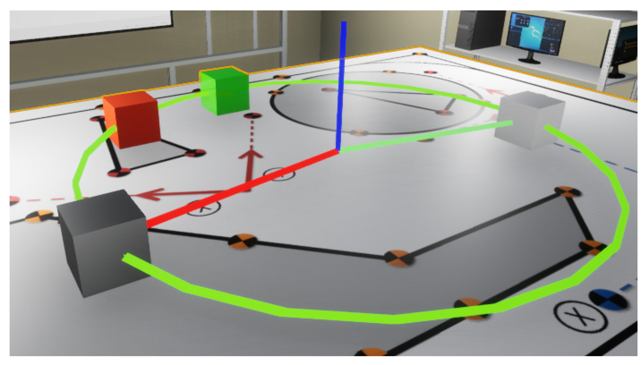
By drawing the debug circles and lines the circle defined by a, b, c points and vector can also be observed. On the following figure, the grey cube signifies the starting position, the orange cube the Aux point, and the white cube the end point, while the green one is executing the circular movement. CIRC motion in cyber space is shown in Figure 16.
The vector, which is illustrated with the red line, is rotated around the vector illustrated with the blue line. The output of “RotateVectorAroundAxis” is a vector, to which if we add the coordinate of the origin of the circle, we get the endpoint of the movement. Using the combination of Timeline and Lerp, smooth circular motion can be achieved, assuming that input value of A is 0, and input value of B is the degree of rotation. The output of the lerp is connected to the Angle Deg input of the rotation.
In the case of a unit circle with its center at the origin of the coordinate system, placed on the XY plane, the following are true: if , then . However, if and a, c remains unchanged then the value of will still stay the same. For this reason, a secondary checking is necessary using another “RotateVectorAroundAxis” node. If the “In Vect” and “Axis” inputs are same as the existing node, but Angle Deg’s value is , then the output vector with the circle’s origin point added to it should be the coordinates of end location. Comparing this with the Aux coordinate, if the two values are equal, the node may use the rotation of angle, if not equal, then will be used. This second checking is done before the start of the movement, so the direction of rotation will be always correct.
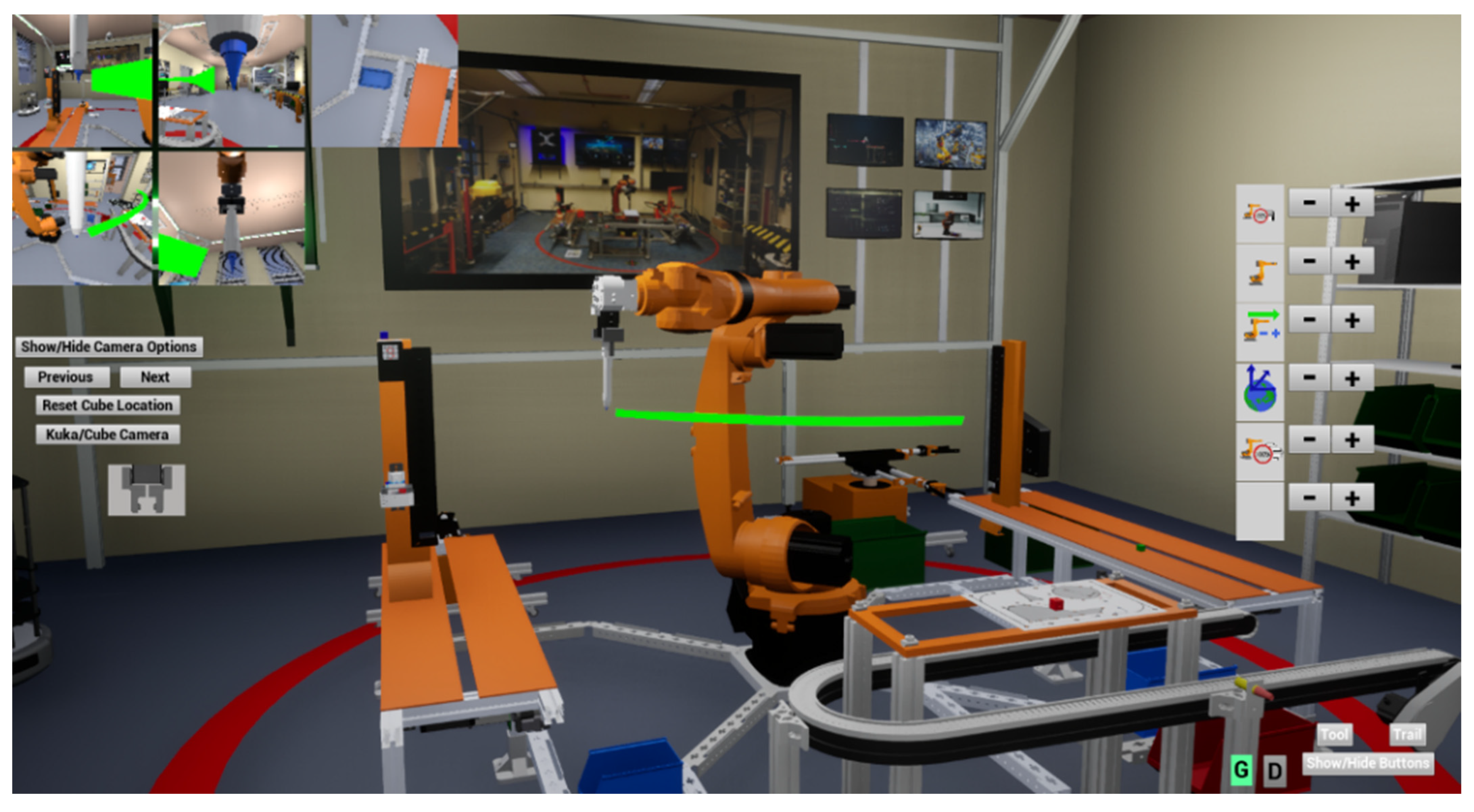
Connecting the “Update” output to the SetActorLocation node, a smooth circular motion can be achieved. The node’s “New Location” input is the output vector of the node “RotateVectorAroundAxis”. Robot control in cyber space is shown in Figure 17.
6. Testing the Effectiveness of Training Using the Virtual Program
A test was conducted with volunteers to determine the effectiveness of the program’s teaching. Students who were never exposed to robot programming in their previous studies have been used to test the software’s impact on education.
The digital twin will be used by various students from the University of Debrecen, Faculty of Engineering. Considering this, it was essential to find volunteers from different groups of students. Overall, 40% of the participants were female, and 60% were male. The age of the participants was between 19 and 25. The students were from the following courses: mechatronics engineering, mechanical engineering, and technical management. Half of the participants were Hungarian students, and the other half of the students came from Asia and Africa, learning English courses.
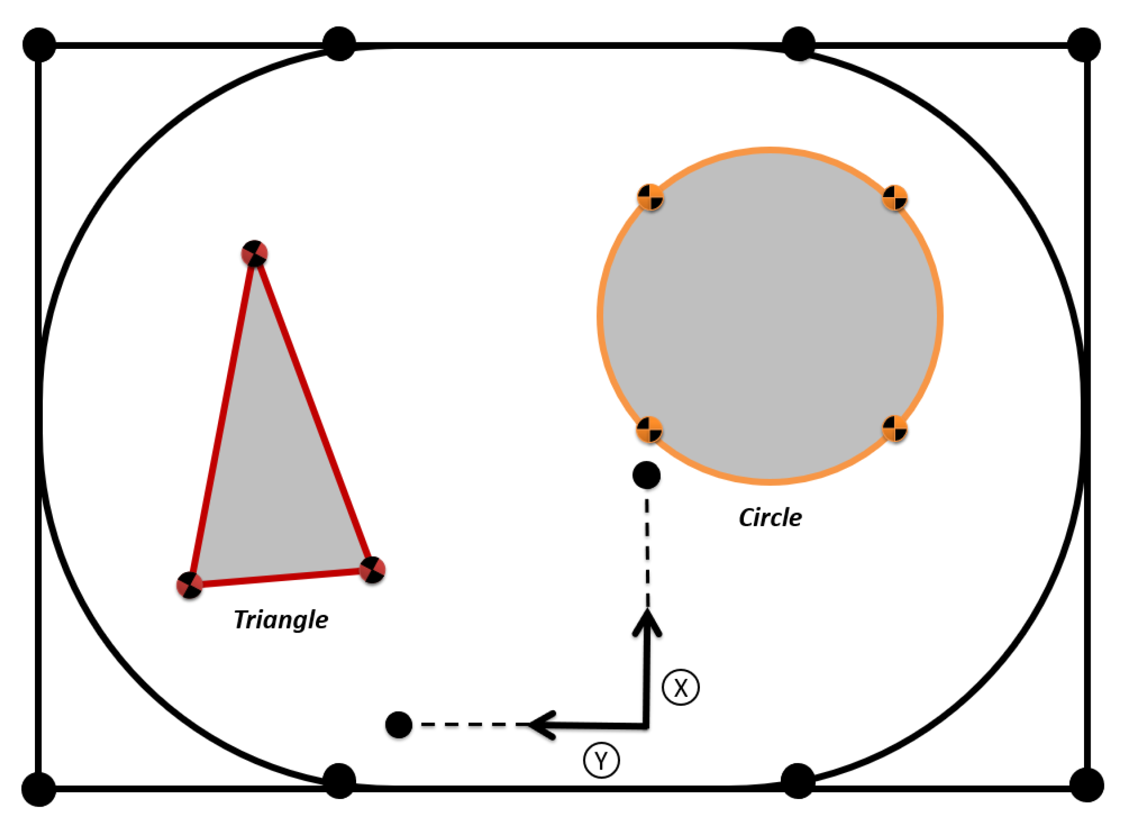
The ten students who agreed to participate in the study were divided into two groups of five. The first group, team A, was given the opportunity to study the cyber space created in Unreal Engine 4, while team B was given the documents used in their education so far. After at least a half hour of preparation, each student was assigned a complex robot control task in physical space on a KUKA KR5 industrial robot. A top view of the two geometric shapes is shown in Figure 18.
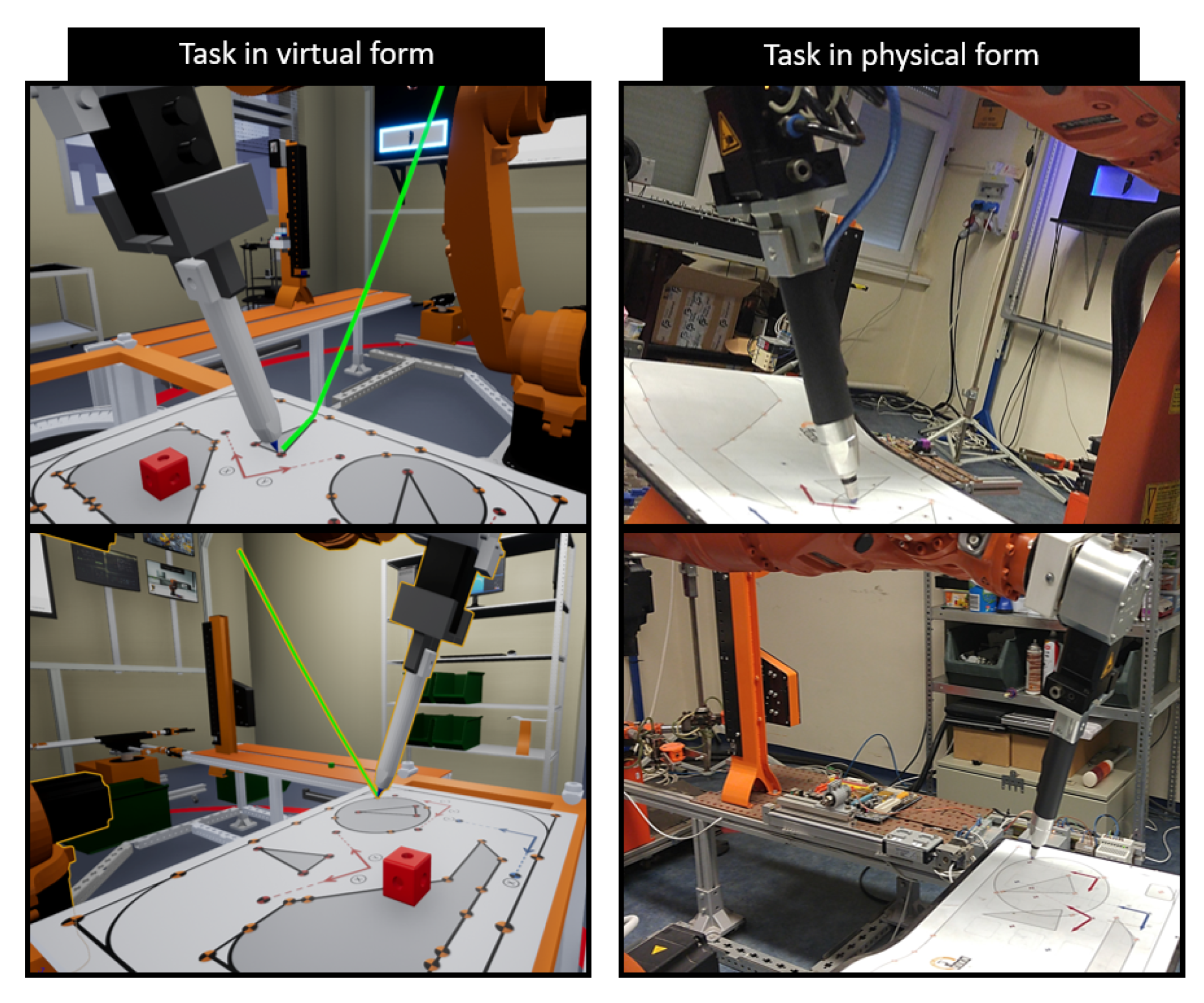
Path training on a sample LIN part using CIRC motion types was required for the task. The time it took the students to complete the task was carefully planned using stopwatches, beginning when they received the Teach Pendant and ending when the robot returned to its home position. At any given time, there was only one student, one supervisor, and one timekeeper in the Robot laboratory. The two tasks, LIN-Triangle and CIRC -Circle, are performed on the sample part shown in Figure 19.
After completing the exercise, the student received feedback via Google forms [59], after selecting whether they used ‘A’ software assistance and ‘B’ traditional teaching aids to prepare before filling out the answers. Responses to the other questions were scaled from 1 to 5 (1—strongly disagree, 5—strongly agree).
To get feedback on the user experience, 10 questions on the system usability scale (SUS) were asked [60]. The feedback shows that the value fell between 3.6–5.0, which means they were satisfied with the program. This indicates that users could use it for training purposes. The results are presented in Table 3.
According to the tables, those who had access to the software were able to complete the two types of tasks more quickly. They were also better prepared and more knowledgeable about how to use the Teach Pendant and robot. Those who had been prepared with traditional materials found it much more difficult to understand how and on what basis the tasks should be solved.
The responses to the Google forms questions indicate that there is a need to expand the educational material using the software. This not only improves efficiency, but it also allows for better distribution of development in other labs, which really is important because lab capacity is limited. However, if the people involved in the training learn how to operate the robot sooner, capacity in the laboratory will be freed up sooner.
7. Discussion
The industry has been using digitalization technologies for some time [61], whether VR [62], AR [63], or digital twin [64]. The applications are wide ranging, both educational and production enhancing. The problem is primarily their integration into a given system or situation. In the absence of uniform standardization [65], there are individual approaches to the problem [66]. Digitalizing individual manufacturing facilities allows flexibility to redesign specific processes to increase efficiency without shutting down the physical production line [67].
The digitalization trend can also help SMEs, as maintaining virtual machines does not necessarily imply purchasing and installing a physical machine [68]. Furthermore, training company professionals in a virtual environment allows them to practice informally, and the risk of physical damage is minimal [69]. In addition, additional 3D models can be added or removed at will, so they can be customized to perform the target task.
In our case, the problem was also to increase efficiency and retain flexibility. Raising the quality of education is part of a complex problem, and it can be determined by the degree course of the participant and the stage of the training period they are at. The study sought to answer whether digitalization, i.e., creating a digital replicant of our industrial robot laboratory, could be a solution in our case. The lab is attended by many students studying other subjects who are at a different stage of their training. Mechanical engineers, mechatronics engineers, and technical managers all cover different fields and have different lab training semesters. Additionally, to avoid lab capacity and clashes with other classes, reduced hours of training are conducted in the industrial lab. Due to the above, it is a serious professional challenge for the teachers involved in the teaching to provide the students with adequate knowledge [70]. The COVID-19 pandemic also posed a serious problem requiring quarantine in case of infection, and travel restrictions made the training impossible [71]. As the virus is still evolving and several variants have emerged, it is difficult to ignore a new wave [72].
The solution to these problems was a digital replica of the Cyber-Physical and Intelligent Robotics Laboratory.
It also provides the possibility to perform PTP, LIN, and CIRC movements with a 6-axis industrial robot. It is important to highlight that, in general, there are often big differences between simulation environments and programming on real robots. The human–machine interface and other functions are usually not integrated into these environments in a one-to-one way or are very far removed from reality. For this reason, those who usually acquire the necessary robot handling skills in such simulation programs are not able to fully operate the machines during physical robot exercises. Taking this into account, the functions in the digital lab are replicated one-to-one to ensure that the participant in the training gain, as much as feasible, identical machine handling abilities when learning virtually. Additionally, by adopting a digital lab, the challenge with lab capacity is resolved because the student can use it anytime without having to be physically there. Exercises were also carried out to assess the program’s impacts on teaching, and the results indicated that teaching using the machine units could be improved. A digital replica of the lab was tested with involved participants. The two teams of 5 people had to perform the same tasks, but one of the teams was given access to the digital lab before programming the physical robot. The tasks were complex, and the execution time was between 15:49 and 31:32 min. For the evaluation, system usability scale questions were asked to the participants and the value fell between 3.6–5.0. It should be remembered that only activities in a virtual environment can give a false sense of security to the user. As even current digital labs cannot physically convey space perception or relative weights of different elements in virtual space. However, even with these features, an individual can still learn to operate a machine more effectively than relying solely on traditional, non-interactive demonstration materials.
Considering the results, it can be said that test participants reacted positively to the virtual lab exercise, and that it is indeed suitable for assisting the participants in the training.
8. Conclusions
Providing students with a high-quality education is a priority. Therefore, practical training must also be competitive and integrate new innovative techniques. Robotic units and other industrial systems with high running costs are a heavy burden for the institution. The study has provided a possible solution to this through the digital twin of the industrial lab, where students have the opportunity to practice in the lab before starting the actual physical training.
However, there is still room for further development, which remains to be explored. Currently, there is no tutorial guide within the application, so the tutor is the person who gives the instructions. No task list currently available would also list the tasks to be performed. Adding these features could help even more in terms of usability. Future development plans include making the digital replica available via a server so that anyone can access the application.
Author Contributions
T.I.E. and R.K. conducted research, established the methodology, designs, and participated in the writing of the paper; G.H. did the formal analysis and review of the paper. All authors have read and agreed to the published version of the manuscript.
Funding
This research received no external funding.
Institutional Review Board Statement
Not applicable.
Informed Consent Statement
Not applicable.
Data Availability Statement
The data presented in this study are available on request from the corresponding author.
Acknowledgments
The authors would like to thank confidential reviewers and the editor for their helpful comments and suggestions. Special thanks to Atosi Roy and Márton Kujbus for their as-sistance with the development of the robot lab.
Conflicts of Interest
The authors declare no conflict of interest.
References
- Nieto-Chaupis, H. Theory and Parameterization of Infections and Waves by Covid-19: A 6-Countries Data Analysis. In Proceedings of the 2021 IEEE 21st International Conference on Bioinformatics and Bioengineering (BIBE), Kragujevac, Serbia, 25–27 October 2021; pp. 1–5. [Google Scholar] [CrossRef]
- Erdei, T.I.; Molnár, Z.; Obinna, N.C.; Husi, G. A Novel Design of an Augmented Reality Based Navigation System & Its Industrial Applications. In Proceedings of the 15th IMEKO TC10—Technical Diagnostics in Cyber-Physical Era, Budapest, Hungary, 6–7 June 2017. [Google Scholar]
- Ferrentino, E.; Salvioli, F.; Chiacchio, P. Globally Optimal Redundancy Resolution with Dynamic Programming for Robot Planning: A ROS Implementation. Robotics 2021, 10, 42. [Google Scholar] [CrossRef]
- Alqahtani, A.Y.; Rajkhan, A.A. E-Learning Critical Success Factors during the COVID-19 Pandemic: A Comprehensive Analysis of E-Learning Managerial Perspectives. Educ. Sci. 2020, 10, 216. [Google Scholar] [CrossRef]
- Gajdzik, B.; Grabowska, S.; Saniuk, S. A Theoretical Framework for Industry 4.0 and Its Implementation with Selected Practical Schedules. Energies 2021, 14, 940. [Google Scholar] [CrossRef]
- Zhang, C.; Wei, B.; Zhang, L. Research on Cyber-Physical Systems Based on Software Definition. In Proceedings of the 2021 IEEE 12th International Conference on Software Engineering and Service Science (ICSESS), Beijing, China, 20–22 August 2021; pp. 174–177. [Google Scholar] [CrossRef]
- Jadala, V.C.; Pasupuletti, S.K.; Raju, S.H.; Kavitha, S.; Bhaba, C.M.H.S.; Sreedhar, B. Need of Intenet of Things, Industrial IoT, Industry 4.0 and Integration of Cloud for Industrial Revolution. In Proceedings of the 2021 Innovations in Power and Advanced Computing Technologies (i-PACT) Kuala Lumpur, Malaysia, Kuala Lumpur, Malaysia, 1–3 July 2021; pp. 1–5. [Google Scholar]
- Aheleroff, S.; Xu, X.; Zhong, R.Y.; Lu, Y. Digital Twin as a Service (DTaaS) in Industry 4.0: An Architecture Reference Model. Adv. Eng. Inform. 2021, 47, 101225. [Google Scholar] [CrossRef]
- UN. Our Common Future. The Brundtland Report, Oslo. 1987. Available online: https://sustainabledevelopment.un.org/content/documents/5987our-common-future.pdf (accessed on 27 August 2022).
- Samadi, E.; Kassou, I. The Relationship between IT and Supply Chain Performance: A Systematic Review and Future Research. Am. J. Ind. Bus. Manag. 2007, 6, 480–495. [Google Scholar] [CrossRef]
- Gereco, A.; Caterino, M.; Fera, M.; Gerbino, S. Digital Twin for Monitoring Ergonomics during Manufacturing Production. Appl. Sci. 2020, 10, 7758. [Google Scholar] [CrossRef]
- Carvalho, R.; da Silva, A.R. Sustainability Requirements of Digital Twin-Based Systems: A Meta Systematic Literature Review. Appl. Sci. 2021, 11, 5519. [Google Scholar] [CrossRef]
- Rivera, L.; Müller, H.; Villegas, N.; Tamura, G.; Jiménez, M. On the Engineering of IoT-Intensive Digital Twin Software Systems. In Proceedings of the IEEE/ACM 42nd International Conference on Software Engineering Workshops, Seoul, Korea, 27 June–19 July 2020. [Google Scholar]
- Verdouw, C.; Tekinerdogan, B.; Beulens, A.; Wolfert, S. Digital twins in farming systems. Agric. Syst. 2021, 189, 103046. [Google Scholar] [CrossRef]
- Rojek, I.; Mikołajewski, D.; Dostatni, E. Digital Twins in Product Lifecycle for Sustainability in Manufacturing and Maintenance. Appl. Sci. 2021, 11, 31. [Google Scholar] [CrossRef]
- Centomo, S.; Dall’Ora, N.; Fummi, F. The Design of a Digital-Twin for Predictive Maintenance. In Proceedings of the 2020 25th IEEE International Conference on Emerging Technologies and Factory Automation (ETFA), Vienna, Austria, 8–11 September 2020; pp. 1781–1788. [Google Scholar] [CrossRef]
- Rojko, A. Industry 4.0 concept: Background and overview. Int. J. Interact. Mob. Technol. 2017, 11, 77–90. [Google Scholar] [CrossRef]
- Dostatni, E.; Rojek, I.; Hamrol, A. The use of machine learning method in concurrent ecodesign of products and technological processes. In Advances in Manufacturing; Hamrol, A., Ciszak, O., Legutko, S., Jurczyk, M., Eds.; Lecture Notes in Mechanical Engineering; Springer: Berlin, Germany, 2018. [Google Scholar]
- Jamwal, A.; Agrawal, R.; Sharma, M.; Giallanza, A. Industry 4.0 Technologies for Manufacturing Sustainability: A Systematic Review and Future Research Directions. Appl. Sci. 2021, 11, 5725. [Google Scholar] [CrossRef]
- Ademujimi, T.; Prabhu, V. Digital Twin for Training Bayesian Networks for Fault Diagnostics of Manufacturing Systems. Sensors 2022, 22, 1430. [Google Scholar] [CrossRef] [PubMed]
- Ojstersek, R.; Buchmeister, B. The Impact of Manufacturing Flexibility and Multi-Criteria Optimization on the Sustainability of Manufacturing Systems. Symmetry 2020, 12, 157. [Google Scholar] [CrossRef]
- Aheleroff, S.; Mostashiri, N.; Xu, X.; Zhong, R.Y. Mass Personalisation as a Service in Industry 4.0: A Resilient Response Case Study. Adv. Eng. Inform. 2021, 50, 101438. [Google Scholar] [CrossRef]
- Guo, Z.; Zhang, K.; Xin, H.; Bi, M.; He, H.; Hu, W. An optical access network framework for smart factory in the industry 4.0 era supporting massive machine connections. In Proceedings of the 2017 16th International Conference on Optical Communications and Networks (ICOCN), Wuzhen, China, 7–10 August 2017; pp. 1–3. [Google Scholar] [CrossRef]
- Ahmadi Ahangar, T.; Rosin, A.; Nabavi, A.; Palu, I. A review on real-time simulation and analysis methods of microgrids. Int. Trans. Electr. Energy Syst. 2019, 29, e12106. [Google Scholar]
- Badilla-Quintana, M.G.; Sandoval-Henríquez, F.J. Students’ Immersive Experience in Initial Teacher Training in a Virtual World to Promote Sustainable Education: Interactivity, Presence, and Flow. Sustainability 2021, 13, 12780. [Google Scholar] [CrossRef]
- Andhare, P.; Rawat, S. Pick and place industrial robot controller with computer vision. In Proceedings of the 2016 International Conference on Computing Communication Control and automation (ICCUBEA), Pune, India, 12–13 August 2016; pp. 1–4. [Google Scholar] [CrossRef]
- Knoke, B.; Quandt, M.; Freitag, M.; Dieter Thoben, K. Virtual reality training applications in industry—Towards a user-friendly application design. In Competence Development and Learning Assistance Systems for the Data-Driven Future; GITO Verlag: Berlin, Germany, 2021. [Google Scholar]
- El Kharki, K.; Berrada, K.; Burgos, D. Design and Implementation of a Virtual Laboratory for Physics Subjects in Moroccan Universities. Sustainability 2021, 13, 3711. [Google Scholar] [CrossRef]
- Moustakas, L.; Robrade, D. The Challenges and Realities of E-Learning during COVID-19: The Case of University Sport and Physical Education. Challenges 2022, 13, 9. [Google Scholar] [CrossRef]
- Cañas, J.M.; Perdices, E.; García-Pérez, L.; Fernández-Conde, J. A ROS-Based Open Tool for Intelligent Robotics Education. Appl. Sci. 2020, 10, 7419. [Google Scholar] [CrossRef]
- Solak, S.; Yakut, Ö.; Dogru Bolat, E. Design and Implementation of Web-Based Virtual Mobile Robot Laboratory for Engineering Education. Symmetry 2020, 12, 906. [Google Scholar] [CrossRef]
- Cordero-Guridi, J.-d.-J.; Cuautle-Gutiérrez, L.; Alvarez-Tamayo, R.-I.; Caballero-Morales, S.-O. Design and Development of a I4.0 Engineering Education Laboratory with Virtual and Digital Technologies Based on ISO/IEC TR 23842-1 Standard Guidelines. Appl. Sci. 2022, 12, 5993. [Google Scholar] [CrossRef]
- Hernández-Chávez, M.; Cortés-Caballero, J.M.; Pérez-Martínez, Á.A.; Hernández-Quintanar, L.F.; Roa-Tort, K.; Rivera-Fernández, J.D.; Fabila-Bustos, D.A. Development of Virtual Reality Automotive Lab for Training in Engineering Students. Sustainability 2021, 13, 9776. [Google Scholar] [CrossRef]
- Rasheed, G.; Khan, M.; Malik, N.; Akhunzada, A. Measuring Learnability through Virtual Reality Laboratory Application: A User Study. Sustainability 2021, 13, 10812. [Google Scholar] [CrossRef]
- Goode, B. Voice over Internet protocol (VoIP). Proc. IEEE 2002, 90, 1495–1517. [Google Scholar] [CrossRef]
- Kase, D.; Hamamoto, T.; Hangai, S. An interactive quality evaluation of reduced polygon model. In Proceedings of the Proceedings 2000 International Conference on Image Processing (Cat. No. 00CH37101), Vancouver, BC, Canada, 10–13 September 2000; IEEE: Piscataway, NJ, USA, 2000; Volume 2, pp. 879–882. [Google Scholar] [CrossRef]
- Mocanu, B.; Tapu, R.; Petrescu, T.; Tapu, E. An experimental evaluation of 3D mesh decimation techniques. In Proceedings of the ISSCS 2011—International Symposium on Signals, Circuits and Systems, Iasi, Romania, 30 June–1 July 2011; pp. 1–4. [Google Scholar] [CrossRef]
- Koulaxidis, G.; Xinogalos, S. Improving Mobile Game Performance with Basic Optimization Techniques in Unity. Modelling 2022, 3, 201–223. [Google Scholar] [CrossRef]
- Erdei, T.I.; Molnár, Z.; Obinna, N.C.; Husi, G. Cyber physical systems in mechatronic research centre. In Proceedings of the IMTU Oradea—Annual Session of Scientific Papers, Oradea, Romania, 25–27 May 2017. [Google Scholar]
- Sztipanovits, J.; Bapty, T.; Koutsoukos, X.; Lattmann, Z.; Neema, S.; Jackson, E. Model and Tool Integration Platforms for Cyber–Physical System Design. Proc. IEEE 2018, 106, 1501–1526. [Google Scholar] [CrossRef]
- Klapka, O.; Slaby, A. nVidia CUDA Platform in Graph Visualization. In Knowledge, Information and Creativity Support Systems; Kunifuji, S., Papadopoulos, G., Skulimowski, A., Kacprzyk, J., Eds.; Springer: Cham, Switzerland, 2014; Volume 416. [Google Scholar] [CrossRef]
- Patil, G.V.; Deshpande, S.L. Distributed rendering system for 3D animations with Blender. In Proceedings of the 2016 IEEE International Conference on Advances in Electronics, Communication and Computer Technology (ICAECCT), Pune, India, 2–3 December 2016; pp. 91–98. [Google Scholar] [CrossRef]
- Bhawar, P.; Ayer, N.; Sahasrabudhe, S. Methodology to Create Optimized 3D Models Using Blender for Android Devices. In Proceedings of the 2013 IEEE Fifth International Conference on Technology for Education (T4E), Kharagpur, India, 18–20 December 2013. [Google Scholar]
- Spunei, E.; Frumușanu, N.-M.; Muntean, R.; Mărginean, G. Impact of COVID-19 Pandemic on the Educational-Instructional Process of the Students from Technical Faculties. Sustainability 2022, 14, 8586. [Google Scholar] [CrossRef]
- Grodotzki, J.; Upadhya, S.; Tekkaya, A.E. Engineering education amid a global pandemic. Adv. Ind. Manuf. Eng. 2021, 3, 100058. [Google Scholar] [CrossRef]
- Horváth, P.P.; Erdei, T.I.; Husi, G. Restoration and PLC control of a material handling MP-9S industrial manipulator platform. Ann. Oradea Univ. Fascicle Manag. Technol. Eng. 2019, 568, 012060. [Google Scholar] [CrossRef]
- Gorecky, D.; Schmitt, M.; Loskyll, M.; Zühlke, D. Human-machine-interaction in the industry 4.0 era. In Proceedings of the 2014 12th IEEE International Conference on Industrial Informatics (INDIN), Porto Alegre, Brazil, 27–30 July 2014; pp. 289–294. [Google Scholar] [CrossRef]
- Huo, Y.; Yang, A.; Jia, Q.; Chen, Y.; He, B.; Li, J. Efficient Visualization of Large-Scale Oblique Photogrammetry Models in Unreal Engine. ISPRS Int. J. Geo-Inf. 2021, 10, 643. [Google Scholar] [CrossRef]
- Satheesh, P.V. Unreal Engine 4 Game Development Essentials: Master the Basics of Unreal Engine 4 to Build Stunning Video Games; Community Experience Distilled, Packt Publisher: Birmingham, UK, 2016. [Google Scholar]
- Lenovo ThinkCentre M75s. Available online: https://www.lenovo.com/hu/hu/desktops/thinkcentre/m-series-towers/ThinkCentre-M93P/p/11TC1TMM93P (accessed on 16 February 2022).
- Unreal Engine. Powerful Real-Time 3D Creation Tool. Available online: https://www.unrealengine.com/ (accessed on 18 February 2022).
- Niku, S.B. Introduction to Robotics Analysis, Systems, Applications; Prentice Hall: Upper Saddle River, NJ, USA, 2001; pp. 67–71, 92–94. [Google Scholar]
- Paul, R.P. Robot Manipulators: Mathematics, Programming, and Control; The MIT Press: Cambridge, MA, USA, 1981; ISBN 978-0-262-16082-7. [Google Scholar]
- Lőrinc, M. Invers Geometry of Robotics; Sapientia—Hungarian University of Transylvania: Cluj-Napoca, Romania, 2019. [Google Scholar]
- Boyd, R.; Barbosa, S.E. Reinforcement Learning for All: An Implementation Using Unreal Engine Blueprint. In Proceedings of the 2017 International Conference on Computational Science and Computational Intelligence (CSCI), Las Vegas, NV, USA, 14–16 December 2017. [Google Scholar]
- Diaz, S.M. Motion Matching UE4 Santiago Moreno. In Proceedings of the Motion Matching in Unreal Engine 4, Sheffield, UK, 17 May 2019. [Google Scholar]
- KUKA Roboter. KUKA System Software, V5.x; KUKA Roboter GmbH: Augsburg, Germany, 2009. [Google Scholar]
- Brecher, C.; Müller, S.; Kuz, S.; Lohse, W. Towards Anthropomorphic Movements for Industrial Robots. In Proceedings of the 4th International Conference on Digital Human Modeling and Applications in Health, Safety, Ergonomics, and Risk Management: Human Body Modeling and Ergonomics, Las Vegas, NV, USA, 21–26 July 2013; Volume 8026. [Google Scholar]
- Sari, E.; Usman, U.; Hakim, A. Effectiveness of Using Google Forms in the Problem Based Learning Model to Increase the Critical Thinking Ability of High School Students. In Proceedings of the 2nd Educational Sciences International Conference (ESIC 2019), Samarinda, Indonesia, 15–16 September 2019. [Google Scholar]
- Brooke, J. SUS: A Quick and Dirty Usability Scale. Usability Eval; Redhatch Consulting Ltd.: Earley, UK, 1995. [Google Scholar]
- Rolle, R.P.; Martucci, V.D.O.; Godoy, E.P. Digitalization of Manufacturing Processes: Proposal and Experimental Results. In Proceedings of the 2019 II Workshop on Metrology for Industry 4.0 and IoT (MetroInd4.0&IoT), Naples, Italy, 4–6 June 2019; pp. 426–431. [Google Scholar] [CrossRef]
- Zawadzki, P.; Żywicki, K.; Buń, P.; Górski, F. Employee Training in an Intelligent Factory Using Virtual Reality. IEEE Access 2020, 8, 135110–135117. [Google Scholar] [CrossRef]
- Malý, I.; Sedláček, D.; Leitão, P. Augmented reality experiments with industrial robot in industry 4.0 environment. In Proceedings of the 2016 IEEE 14th International Conference on Industrial Informatics (INDIN), Poitiers, France, 19–21 July 2016; pp. 176–181. [Google Scholar] [CrossRef]
- Autiosalo, J.; Ala-Laurinaho, R.; Mattila, J.; Valtonen, M.; Peltoranta, V.; Tammi, K. Towards Integrated Digital Twins for Industrial Products: Case Study on an Overhead Crane. Appl. Sci. 2021, 11, 683. [Google Scholar] [CrossRef]
- Jacoby, M.; Usländer, T. Digital Twin and Internet of Things—Current Standards Landscape. Appl. Sci. 2020, 10, 6519. [Google Scholar] [CrossRef]
- Botín-Sanabria, D.M.; Mihaita, A.-S.; Peimbert-García, R.E.; Ramírez-Moreno, M.A.; Ramírez-Mendoza, R.A.; Lozoya-Santos, J.D.J. Digital Twin Technology Challenges and Applications: A Comprehensive Review. Remote Sens. 2022, 14, 1335. [Google Scholar] [CrossRef]
- Trauer, J.; Pfingstl, S.; Finsterer, M.; Zimmermann, M. Improving Production Efficiency with a Digital Twin Based on Anomaly Detection. Sustainability 2021, 13, 10155. [Google Scholar] [CrossRef]
- Yasin, A.; Pang, T.Y.; Cheng, C.-T.; Miletic, M. A Roadmap to Integrate Digital Twins for Small and Medium-Sized Enterprises. Appl. Sci. 2021, 11, 9479. [Google Scholar] [CrossRef]
- Kaarlela, T.; Arnarson, H.; Pitkäaho, T.; Shu, B.; Solvang, B.; Pieskä, S. Common Educational Teleoperation Platform for Robotics Utilizing Digital Twins. Machines 2022, 10, 577. [Google Scholar] [CrossRef]
- Aguirre, T.; Aperribai, L.; Cortabarría, L.; Verche, E.; Borges, Á. Challenges for Teachers’ and Students’ Digital Abilities: A Mixed Methods Design Study. Sustainability 2022, 14, 4729. [Google Scholar] [CrossRef]
- Zubair, H.; Karoonsoontawong, A.; Kanitpong, K. Effects of COVID-19 on Travel Behavior and Mode Choice: A Case Study for the Bangkok Metropolitan Area. Sustainability 2022, 14, 9326. [Google Scholar] [CrossRef]
- He, S.; Yang, J.; He, M.; Yan, D.; Tang, S.; Rong, L. The risk of future waves of COVID-19: Modeling and data analysis. Math. Biosci. Eng. 2021, 18, 5409–5426. [Google Scholar] [CrossRef]
Figure 1.
The cyber-physical and intelligent robot systems laboratory.

Figure 2.
Architecture model of CPS.

Figure 3.
The designed and optimized KUKA KR5 3D model.

Figure 4.
The digital version of CPS Laboratory.

Figure 5.
KUKA KR5 work area in LIT and wire views in Unreal Engine 4.

Figure 6.
Change between Robot Cell cameras.

Figure 7.
The Teach Pendant of KUKA KR5.

Figure 8.
KUKA KR5 Virtual HMI—Widget Designer Tab.

Figure 9.
Blueprint of the On Clicked Up Arrow event.

Figure 10.
The user interface of the digital twin compared to the teach pendant.

Figure 11.
Designed virtual user interface. Symbols used in the DH table have predefined meanings, which are as follows: θ: Rotation along Z axis; d: Movement along Z axis (distance); a: Joint offset (length of normal); α: Angle difference of two consecutive joints (joint twist) [52].
Figure 11.
Designed virtual user interface. Symbols used in the DH table have predefined meanings, which are as follows: θ: Rotation along Z axis; d: Movement along Z axis (distance); a: Joint offset (length of normal); α: Angle difference of two consecutive joints (joint twist) [52].

Figure 12.
AnimGraph in the Animation Blueprint.

Figure 13.
Axis rotation value overwrite in Control Rig.

Figure 14.
PTP, LIN, CIRC—axis specific movement.

Figure 15.
Circle center calculation in Unreal Engine.

Figure 16.
CIRC motion in cyber space.

Figure 17.
Robot control in cyber space.

Figure 18.
Standard path training tool.

Figure 19.
Task in virtual and physical form.


Table 1.
Team “A” results depending on the use of the program.
| A Team-Blue | |||
|---|---|---|---|
| LIN-Triangle | CIRC-Circle | Total Time | |
| 1 | 6:18 | 12:27 | 18:45 |
| 2 | 8:45 | 10:16 | 19:01 |
| 3 | 4:35 | 9:56 | 14:31 |
| 4 | 9:27 | 15:37 | 25:04 |
| 5 | 7:03 | 8:46 | 15:49 |
Table 2.
Team “B” results depending on the use of the program.
| B Team-Red | |||
|---|---|---|---|
| LIN-Triangle | CIRC-Circle | Total Time | |
| 1 | 14:24 | 16:37 | 31:01 |
| 2 | 8:36 | 18:47 | 27:47 |
| 3 | 10:22 | 15:36 | 25:36 |
| 4 | 17:01 | 11:18 | 28:19 |
| 5 | 9:34 | 21:58 | 31:32 |
Table 3.
The 10 questions and sus score.
| No. | The Statement | Mean ± SD | Range |
|---|---|---|---|
| Q1 | The virtual CPS program is user-friendly. | 4.8 ± 0.4 | 4–5 |
| Q2 | The virtual CPS program is useful to understand robot controls. | 4.4 ± 0.49 | 4–5 |
| Q3 | I felt confident using the program. | 4.4 ± 0.8 | 3–5 |
| Q4 | The program is useful for teaching the motions. | 5 ± 0 | 5 |
| Q5 | The virtual lab has aided in my understanding of logistical issues. | 3.6 ± 0.49 | 3–4 |
| Q6 | I think the HMI and robot functions are well-integrated. | 4.6 ± 0.49 | 4–5 |
| Q7 | I believe that the virtual CPS program’s support for practice makes it more useful. | 4.2 ± 0.4 | 4–5 |
| Q8 | I believe that the virtual CPS program has applications in other areas as well. | 4 ± 0.632 | 3–5 |
| Q9 | I support the fact that most users will learn machine control more quickly using it. | 4.8 ± 0.4 | 4–5 |
| Q10 | The CPS Lab has been able to increase my interest in robot arms. | 5 ± 0 | 5 |
Publisher’s Note: MDPI stays neutral with regard to jurisdictional claims in published maps and institutional affiliations. |
© 2022 by the authors. Licensee MDPI, Basel, Switzerland. This article is an open access article distributed under the terms and conditions of the Creative Commons Attribution (CC BY) license (https://creativecommons.org/licenses/by/4.0/).
Share and Cite
MDPI and ACS Style
Erdei, T.I.; Krakó, R.; Husi, G. Design of a Digital Twin Training Centre for an Industrial Robot Arm. Appl. Sci. 2022, 12, 8862. https://doi.org/10.3390/app12178862
AMA Style
Erdei TI, Krakó R, Husi G. Design of a Digital Twin Training Centre for an Industrial Robot Arm. Applied Sciences. 2022; 12(17):8862. https://doi.org/10.3390/app12178862
Chicago/Turabian StyleErdei, Timotei István, Rudolf Krakó, and Géza Husi. 2022. "Design of a Digital Twin Training Centre for an Industrial Robot Arm" Applied Sciences 12, no. 17: 8862. https://doi.org/10.3390/app12178862
Note that from the first issue of 2016, this journal uses article numbers instead of page numbers. See further details here.