Article

Development of Damage Type Viscoelastic Ontological Model for Soft and Hard Materials under High-Strain-Rate Conditions

1
Institute of Defense Engineering, PLA Academy of Military Science, Beijing 100850, China
2
Institute of Engineering Safety and Disaster Prevention, Hohai University, Nanjing 210098, China
3
State Key Laboratory of Mining Response and Disaster Prevention and Control in Deep Coal Mines, Anhui University of Science and Technology, Huainan 232001, China
*
Author to whom correspondence should be addressed.
Appl. Sci. 2022, 12(17), 8407; https://doi.org/10.3390/app12178407
Submission received: 8 May 2022 / Revised: 9 August 2022 / Accepted: 11 August 2022 / Published: 23 August 2022

Abstract

:
By improving the ZWT model, a principal structure model applicable to both soft and hard materials under dynamic loading conditions was obtained. Dynamic mechanical experiments were conducted using SHPB to obtain stress–strain curves for coal rock and foam concrete. The ZWT intrinsic model was simplified according to the dynamic impact characteristics of concrete, and the intrinsic model was established by introducing macroscopic damage quantity D and correction factor δ. The stress–strain curves of coal rock, foamed concrete, steel fiber concrete, granite, lightweight foamed concrete, and EPS concrete at different strain rates were used to validate the present constitutive model and prove the correctness of the model.

1. Introduction

Disasters caused by dynamic loads have occurred [1,2,3,4]. Soft and hard materials are commonly used materials in protective works [5,6,7,8,9]. Because dynamic load experiments are often difficult, numerical simulations are the most common means [10,11,12,13,14]. Many scholars have made outstanding contributions to the study of the present constitutive model, which directly affects the accuracy of numerical simulations [15,16]. The selection of the principal structure model directly affects the accuracy of the calculation, and most of the current principal structure models are only applicable to soft or hard materials, lacking a more general dynamic principal structure model. Therefore, it is important to establish a more general intrinsic structure model for the rapid selection of the intrinsic structure model for numerical simulation.
The ZWT instantonal model can describe static and impact loads well and the strain rates described by the ZWT instantonal model range from 10−4 to 103 s−1. Initially, Tang first proposed a nonlinear viscoelastic instantonal equation that can describe the kinetic behavior of epoxy resin, and the instantonal model can describe eight magnitudes of strain rates, which is called the ZWT instantonal model. Many scholars have improved the ZWT intrinsic model and established the instrinsic model for certain materials. The ZWT intrinsic model has been widely used in the fields of polymer materials, concrete materials, and soils. Luo et al. [17] studied the mechanical properties of TDE86 epoxy resin at different temperatures, established the ZWT intrinsic structure model of epoxy resin containing nine parameters, and verified the applicability of the ZWT intrinsic structure model at different temperatures by developing a subroutine. Liu et al. [18], according to the principle of building the constitutive model of polymer material, added the one-dimensional structure of the ZWT material constitutive model to the dashpot element in parallel, in which strain rate and coefficient of viscosity were introduced and the nonlinear viscoelastic constitutive model of Polycarbonate material was achieved; this intrinsic structure model contains 14 parameters. Xu et al. [19] developed a ZWT nonlinear viscoelastic model, which contains 10 parameters. The standard ZWT nonlinear viscoelastic model was selected to predict the elastic behavior of LNBR/epoxy composites under a wide range of strain rates in this study.
However, the damage of materials such as concrete and soil is guided by the generation of damage such as microcracks and microporosity, and these microscopic defects are the main cause of damage softening of materials. In order to reflect the main cause of microscopic defects on the softening of material damage and to reflect the effect of microscopic defects on the softening of material damage, numerous scholars have considered damage in improving the ZWT intrinsic structure model. Zhang et al. [20] established the dynamic principal structure relationship of BFRC by improving the ZWT model and fitted the stress–strain curve using the new equation, which has 10 parameters. Zhang et al. [21] developed an ontogenetic model of PFRC based on the ZWT ontogeny, which has nine parameters. Li et al. [22] combined the discrete ZWT model with the D-P yielding criterion to develop a permafrost intrinsic model with 10 parameters. Ma et al. [23] conducted dynamic mechanical experiments on frozen sandy soils by SHPB, and developed a dynamic native model of frozen sandy soils containing 12 parameters on the basis of the ZWT native model. Fu et al. [24] developed a viscoelastic intrinsic model with temperature sensitivity based on the ZWT intrinsic model, which has 15 parameters. Zhang et al. [25] tested the dynamic mechanical properties of permafrost at different temperatures and high strain rates using SHPB and established a dynamic intrinsic model of permafrost, which predicts results in good agreement with experimental results, and the model has 11 parameters. It can be seen that the ZWT intrinsic structure model is used in many materials, which proves that the ZWT intrinsic structure model has great applicability in research and industry all over the world, and therefore deserves further study. However, the existing model has many parameters, and the calibration parameters are tedious for researchers, which is not conducive to the promotion of the ZWT intrinsic structure model, so it is necessary to establish a dynamic intrinsic structure model with fewer parameters and which is more general.
In this paper, the ZWT principal structure model was simplified to contain only four parameters according to the kinetic properties, and the applicable range was extended by introducing damage and correction coefficients to establish a principal structure model containing only seven parameters. The fitting effect was verified by the SHPB test data of coal rock and foam concrete, and the obtained goodness of fit was high, which verifies the universal applicability of the intrinsic constitutive model established in this paper.

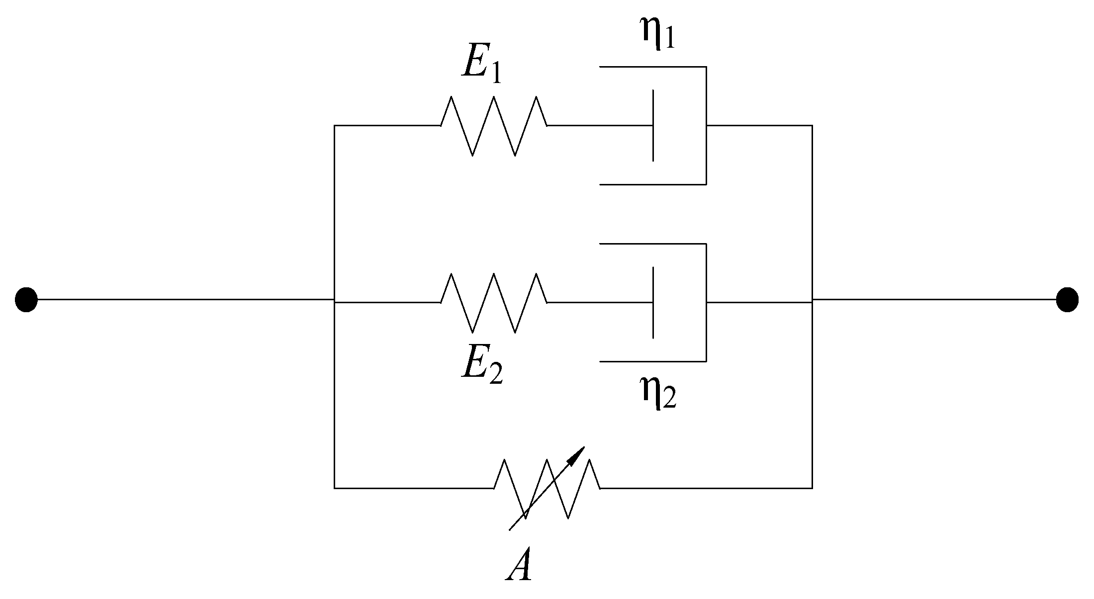
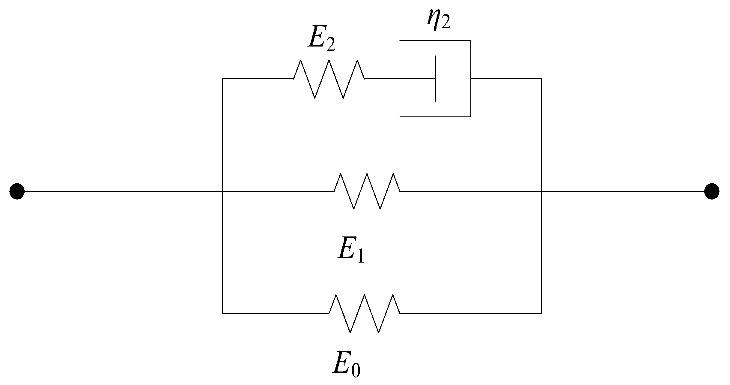
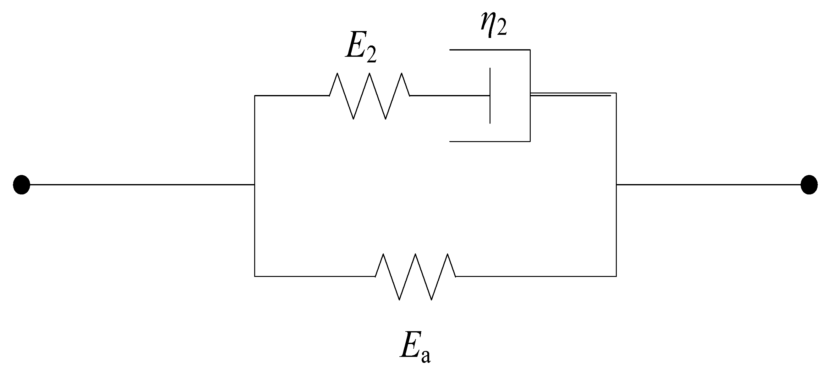
2. Establishment of Constitutive Model

The Zhu–Wang–Tang (ZWT) intrinsic model was proposed by Zhu Zhaoxiang, Wang Lili, and Tang Zhiping, the famous Chinese mechanics scholars, which can simulate the nonlinear viscoelastic intrinsic relationship of engineering plastics in the range of quasi-static load to impact load well. The main application objects of the original ZWT principal structure model are engineering plastics, including epoxy resin, plexiglass PMMA, polycarbonate PC, nylon, ABS, and PBT, etc. Concrete and rock is a typical non-homogeneous material, and there are a large number of defects inside the material, such as particle boundaries, pores, fissures and soft media, etc. The influence of damage on dynamic strength needs to be considered under high-strain-rate conditions. For the original ZWT instantonal model, it contains eight parameters, and there will be more parameters after considering the damage, and some equations of the original ZWT instantonal models do not work under the high-strain-rate conditions. Therefore, it is necessary to improve and simplify the ZWT instantonal model so that it can be applied to non-homogeneous materials. The development of a damage type viscoelastic instantonal model for soft and hard materials under high-strain-rate conditions is of practical significance for the study of the mechanical response of non-homogeneous materials under high-strain-rate conditions. Instantonal models are models that describe the short-term mechanical changes of materials and are mainly used in the field of dynamics.
Considering the strain hardening and strain rate hardening of the material in dynamic experiments, the existing Zhu–Wang–Tang constitutive model can be well expressed. The ZWT constitutive model is the equation expression used to express the impact resistance of materials, and the formula is as follows:
σ = σ e + σ m 1 + σ m 2 = E 0 ε + α ε 2 + β ε 3 + E 1 0 t ε ( τ ) exp ( t τ θ 1 ) d τ + E 2 0 t ε ( τ ) exp ( t τ θ 2 ) d τ
α, β, E 0 represent the elastic constant of nonlinear spring; two integral terms represent the Maxwell body with different relaxation degrees, where θ 1 represents relaxation time of the Maxwell viscoelastic response at low strain rate, θ 2 represents the relaxation time of the Maxwell viscoelastic response at high strain rate, E 1 , E 2 represent the elastic constants of the Maxwell body. The constitutive model can be expressed by the mechanical model composed of a spring sticky pot, as shown in Figure 1.
In view of the actual mechanical properties under dynamic loading summarized in the experiment and the physical significance of the “Zhu–Wang–Tang” constitutive model, the following simplifications or improvements are made as follows:
(a) Simplification I. For the first term of the equation of σ e = E 0 ε + α ε 2 + β ε 3 , the meaning is strain rate-independent equilibrium stress, which describes the nonlinear elasticity of the material. Often, the elastic part in dynamic experiments can be considered as linear. The trinomial of the first term can be simplified into monomial, that is, σ e = E 0 ε ; the nonlinear spring in the corresponding ZWT constitutive model becomes a linear spring. With this method, the constitutive model is simplified, and the simplified formula of the ZWT constitutive model is:
σ = σ e + σ m 1 + σ m 2 = E 0 ε + E 1 0 t ε ( τ ) exp ( t τ θ 1 ) d τ + E 2 0 t ε ( τ ) exp ( t τ θ 2 ) d τ
(b) Simplification II. In the dynamic loading experiment of SHPB in this paper, the impact loading time is very short. The loading time scale of the low-frequency Maxwell body was between 100 and 102 s. Therefore, the loading time in this experiment is not one order of magnitude as that of the low-frequency Maxwell body, and the former is much smaller than the latter. Therefore, when the dynamic load is completed, the low-frequency Maxwell body is not able to relax. Therefore, the second medium-low-frequency Maxwell body in the ZWT constitutive model can be replaced by a simple spring. The simplified physical model is shown in Figure 2, and the formula of the ZWT constitutive model can be further simplified as:
σ = σ e + σ m 1 + σ m 2 = E 0 ε + E 1 ε + E 2 0 t ε ( τ ) exp ( t τ θ 2 ) d
As shown in Figure 3, springs E0 and E1 are parallel, and a simple spring E a can replace the two parallel springs. The equivalent physical model is shown in Figure 3. The ZWT constitutive model is further simplified to:
σ = σ e + σ m 1 + σ m 2 = E a ε + E 2 0 t ε ( τ ) exp ( t τ θ 2 ) d τ
(c) Improvement I. The material cannot be completely evenly distributed in the production process of composite concrete. From a microscopic point of view, there are disordered micropores and micro-cracks inside, so the damage factor must be considered when establishing the constitutive model. The distribution of micro-pores and micro-cracks in concrete is very complex and has great discreteness. In order to simplify the model, the continuum damage mechanics method is adopted, that is, the composite concrete is assumed to be a continuous medium. The macroscopic damage D is introduced to evaluate the damage degree of composite concrete. According to the Lemaitre strain equivalence principle, the basic form of the constitutive model is as follows:
σ a = ( 1 D )   σ r
In this formula, σa represents effective stress; σr represents the original stress; and D represents the damage variable.
Strain and strain rate will affect the damage evolution process, and the damage evolution equation is as follows:
D = A × ( ε ε 0 ) α ε β
In this formula, ε 0 = 10 4 s 1 represents the reference value of the strain rate; ε represents the strain rate; and A, α, and β represent undetermined coefficients respectively.
In summary, the Equations (4)–(6) can be obtained as:
σ a = ( 1 D ) σ r = [ 1 A ( ε ε 0 ) α ε β ] [ E a ε + E 2 0 t ε ( τ ) exp ( t τ θ 2 ) d τ ]
Considering that SHPB is approximately assumed to be constant strain rate, the constitutive model can be rewritten as follows:
σ a = ( 1 D ) σ r = [ 1 A ( ε ε 0 ) α ε β ] { E a ε + E 2 θ 2 ε [ 1 exp ( ε θ ε 2 ) ] }  
Although the improved ZWT constitutive model in this paper considers the damage factor, it still assumes that the material is continuous. In reality, there are a series of uncertainties in the material such as voids, cracks, and in homogeneous weave that may lead to early or delayed arrival of the stress maximum in the stress–strain curve. In order to characterize this uncertainty factor, correction factor δ was introduced to correct the fitting curve. Finally, the dynamic damage constitutive model with the correction factor is obtained as follows:
σ a = ( 1 D ) σ r = [ 1 A ( ε ε 0 ) α ( ε + δ ) β ] { E a ( ε + δ ) + E 2 θ 2 ε [ 1 exp ( ( ε + δ ) θ ε 2 ) ] }

3. Experimental Research

In order to verify the general applicability of the viscoelastic constitutive model with damage established in this paper to hard and soft materials, dynamic mechanical experiments of hard and soft materials were carried out in this paper. The hard material was coal rock, and the soft material was selected as foam concrete. The stress–strain curve of the material was obtained by SHPB experiment. In this paper, the stress–strain curve obtained from the experiment was used to verify the constitutive model.

3.1. Preparation of Test Pieces

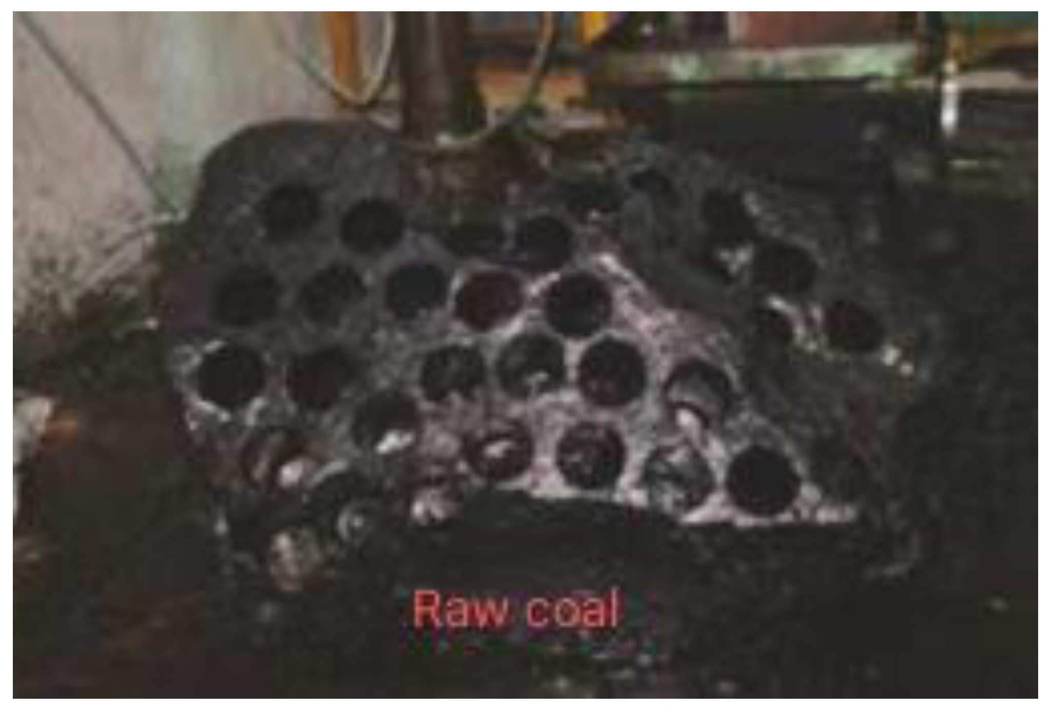
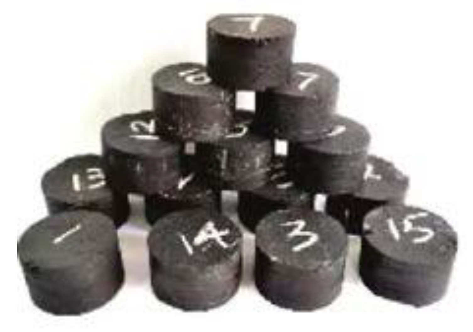
3.1.1. Preparation of Coal Rock

The coal sample for this test was taken from the 13-1 coal seam of the Zhangji Coal Mine of Huainan Mining Group, China. We took out the large coal body just exposed on the coal mining face, wrapped it in a sealed bag, and vacuumized it. After the raw coal arrived in the laboratory, it was cored with a rock drilling rig, and then cut and polished to prepare a coal-rock specimen with a diameter of 75 mm and a height of 35 mm. The drilling of the raw coal specimen is shown in Figure 4, and the dynamic mechanical specimen is shown in Figure 5. Zhang et al. [26] conducted a static compressive test on the same coal rock as that used in this paper, and the test result was 17.67 MPa.

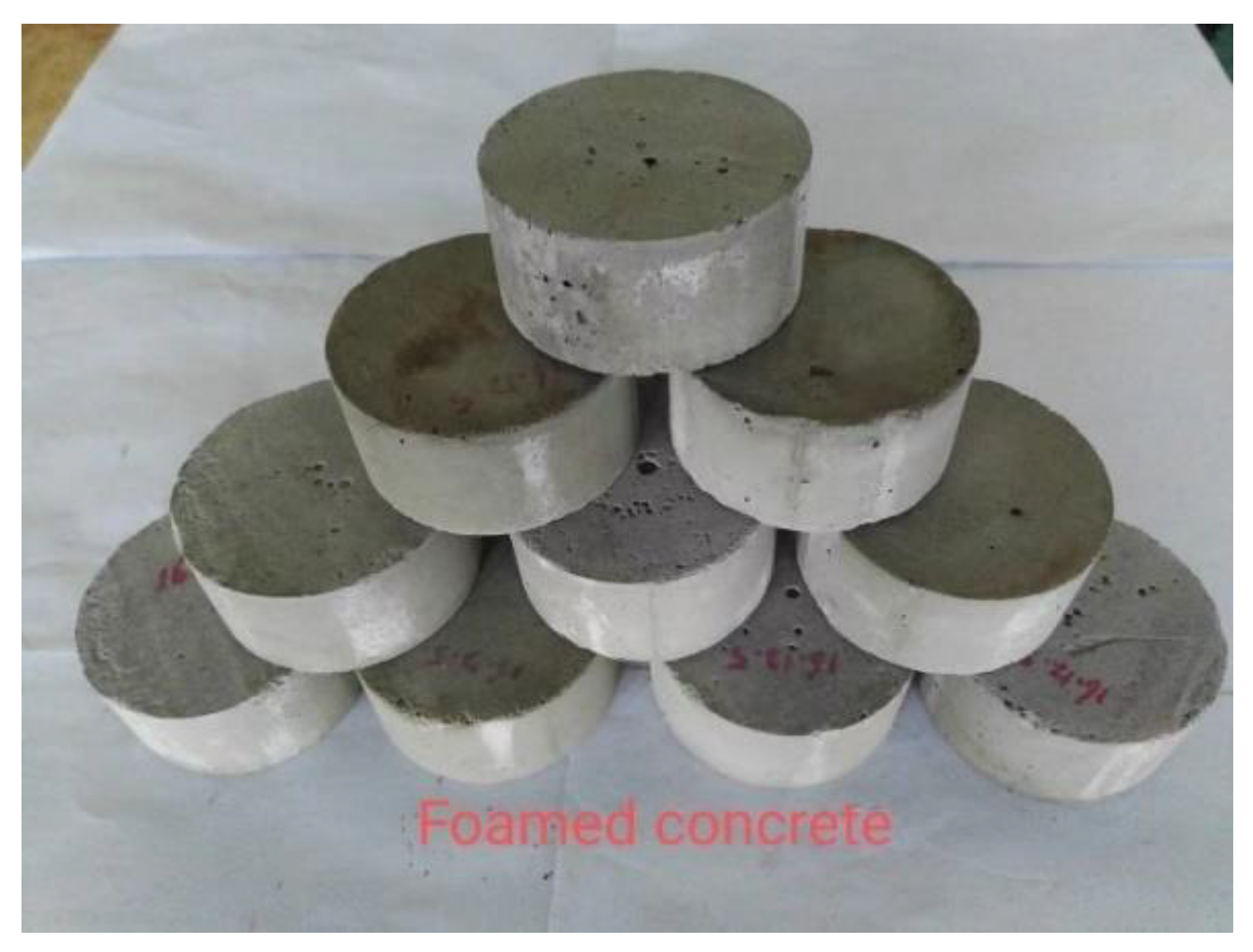
3.1.2. Preparation of Foam Concrete

The composition of foam concrete includes cement, fly ash, water, and foam mixed uniformly. More detailed information on the raw materials is listed in Table 1. The amount of each raw material added is shown in Table 2. After sufficient mixing, concrete specimens with a diameter of 75 mm and a height of 35 mm were supported, as shown in Figure 6. In order to ensure the rationality of preparing foam concrete, this paper refers to the preparation parameters in the paper of He et al. [7], which recorded a static compressive strength of about 6 Mpa.

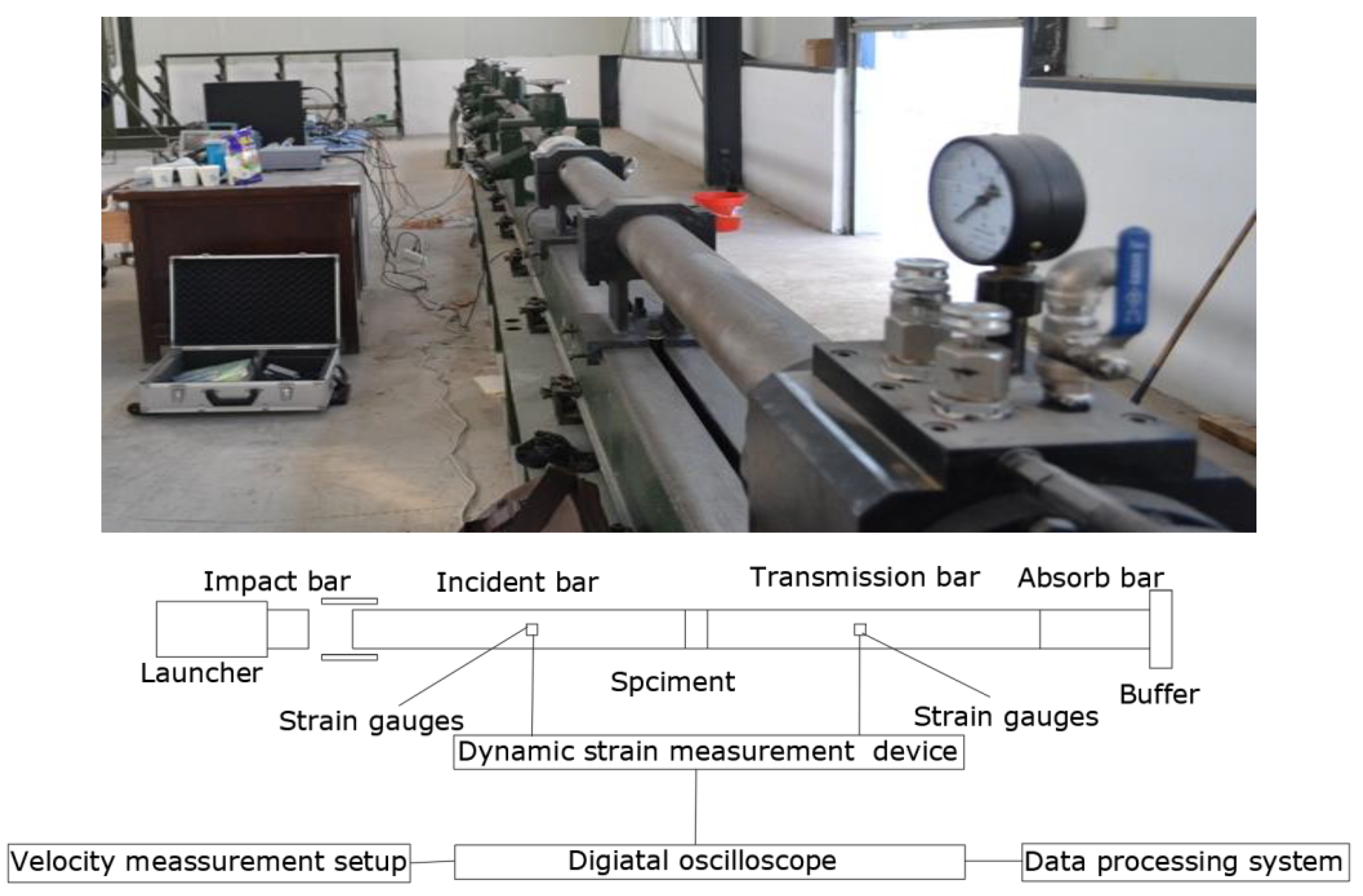
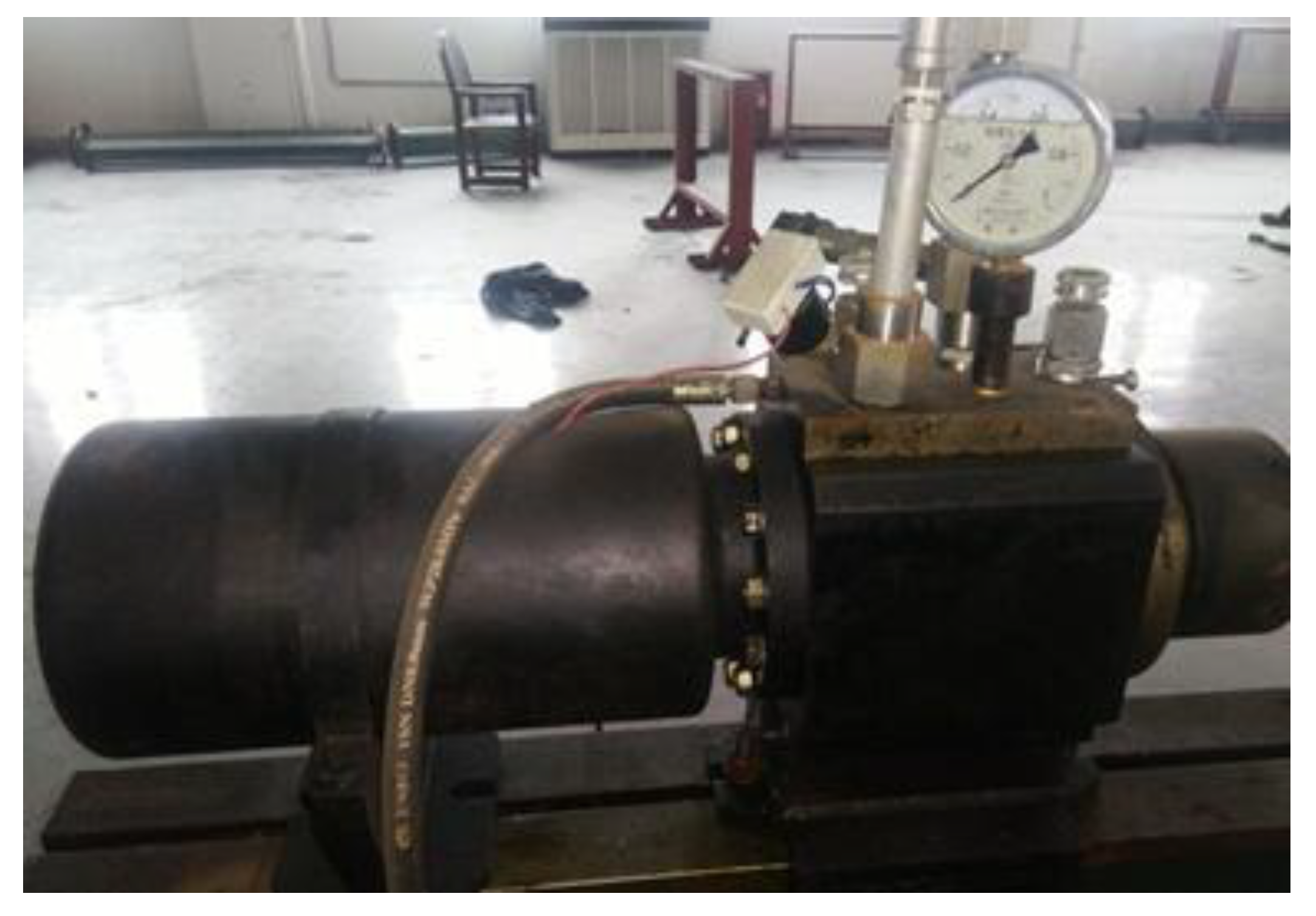
3.2. Experimental Method

Using the split Hopkinson bar experiment technology, the impact bar, incident bar, and transmission bar were high-strength bars, and the lengths were 400 mm, 4000 mm, and 2500 mm, respectively. The schematic diagram of the SHPB experimental device is shown in Figure 7.
In this paper, the power system was driven by high-pressure gas, and data acquisition was conducted by USING a TP-5-12 semiconductor strain gauge and a DHHP-20 ultra-dynamic strain gauge, and DHHP dynamic signal analysis software was used for data analysis. The power system device is shown in Figure 8, the TP-5-12 semiconductor strain gauge is shown in Figure 9, the DHHP-20 ultra-dynamic strain gauge is shown in Figure 10, and the DYNAMIC signal analysis of DHHP is shown in Figure 11.

3.3. Verification of Stress Balance

In the SHPB test, the reliability of test results depends on the stress balance before and after the specimen failure, so it is necessary to verify the stress balance. Figure 12 shows the stress balance at both ends of the specimen. The sum of incident wave stress and reflected wave stress was basically equal to transmitted wave stress, so the experimental results are reliable.

3.4. Data Analysis

The SHPB experiment refers to the elastic stress wave propagation theory and adopts two basic assumptions [27,28,29]: (1) one-dimensional stress wave assumes that the cross section of the rod is always planar; (2) stress uniformity is assumed, that is, the stress wave propagates in the specimen, and stress is equal everywhere in practice. The experimental principle is to measure the incident wave, reflected wave, and pulse in the transmission rod by the strain gauge, and then deduce the stress–strain relationship of the specimen according to one-dimensional stress wave theory.
In this paper, the three-wave method was used to calculate the stress σ ¯ ( t ) , strain rate ε ˙ ¯ ( t ) , and strain   ε ¯ ( t ) of the specimen from the strain waveform in the elastic rod, namely:
{ σ ¯ ( t ) = E A 2 A 0 [ ε i ( t ) + ε r ( t ) + ε t ( t ) ] ε ˙ ¯ ( t ) = C L 0 [ ε i ( t ) ε r ( t ) ε t ( t ) ] ε ¯ ( t ) = C L 0 0 t [ ε i ( t ) ε r ( t ) ε t ( t ) ] d t
In the formula, E, C0, and A are the elastic modulus, elastic wave velocity, and sectional area of the rod, respectively. ε i , ε r , and ε t are incident wave strain, reflected wave strain, and transmitted wave strain, respectively. A0 and L0 are the cross-sectional area and length of the specimen, and t is the stress wave continuous specimen.

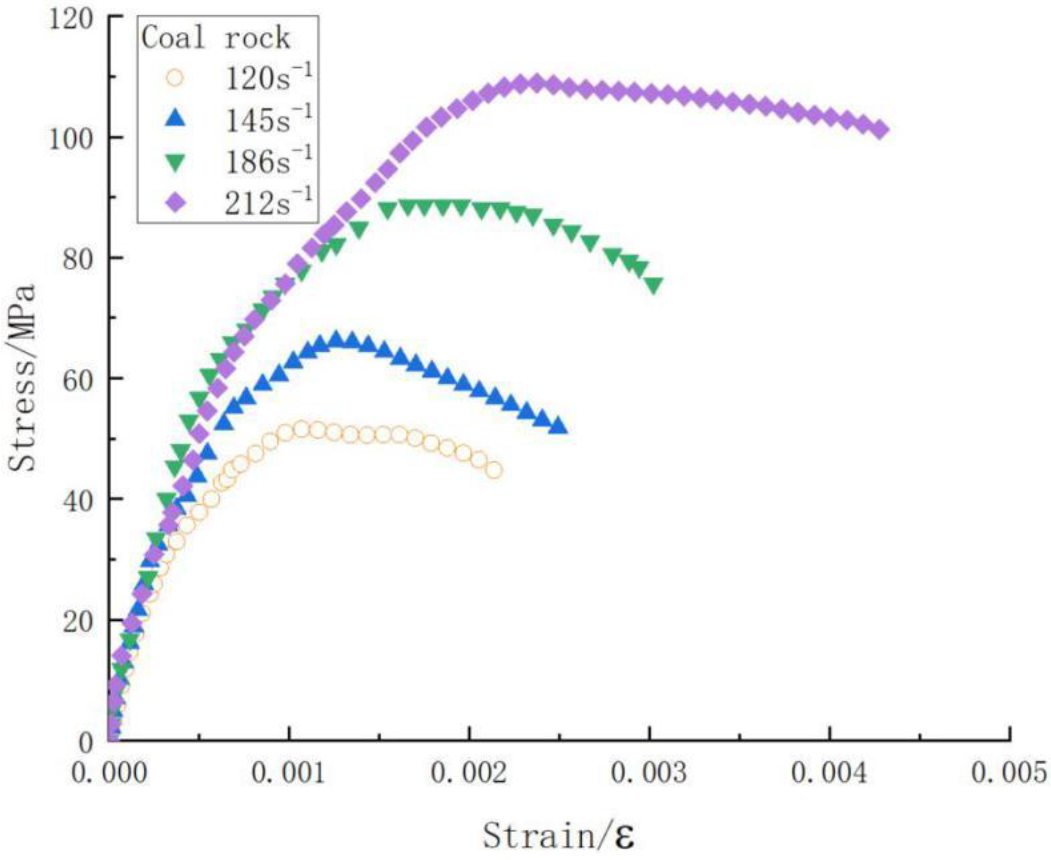
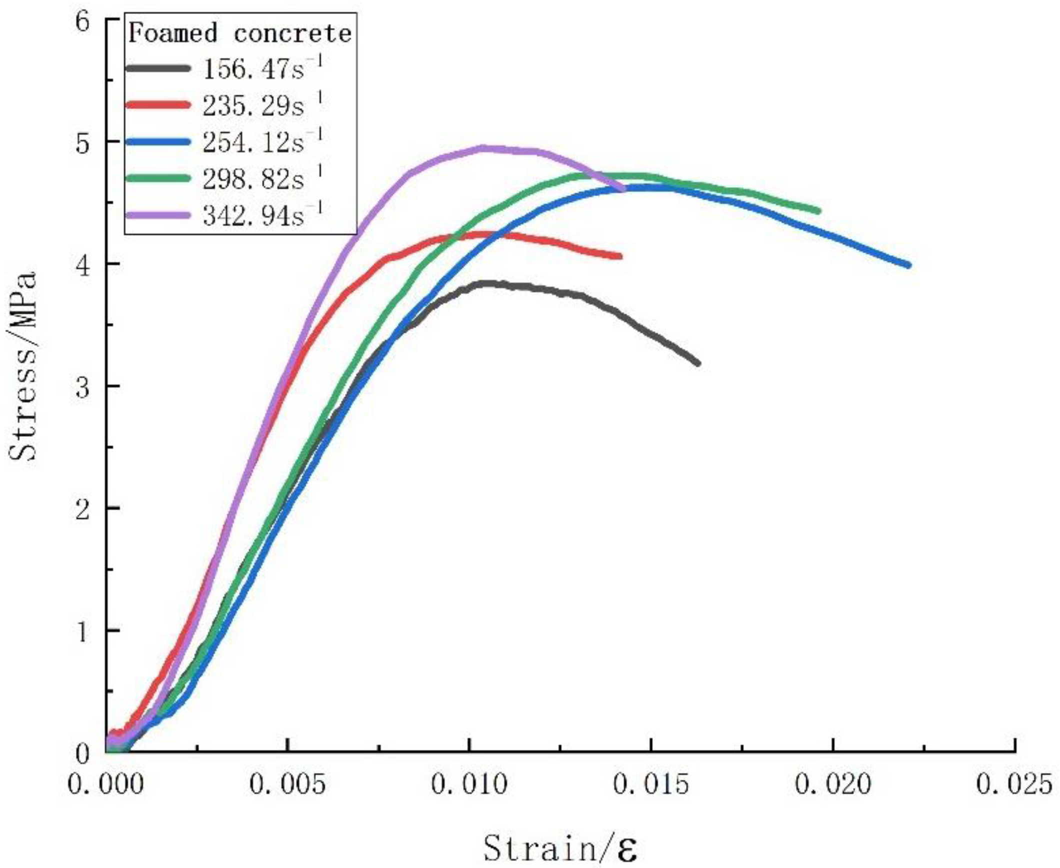
3.5. Experimental Results

Self-made foam concrete was selected as the soft material. The SHPB experiment was carried out by using a Φ50 mm aluminum rod. Hard materials were selected from the coal rock. The impact rod, incidence rod, and transmission rod were selected as the 75 mm steel rod, and the stress–strain curve under different strain rates was obtained. The coal-rock stress–strain curve is shown in Figure 13. The stress–strain curve of foam concrete is shown in Figure 14.

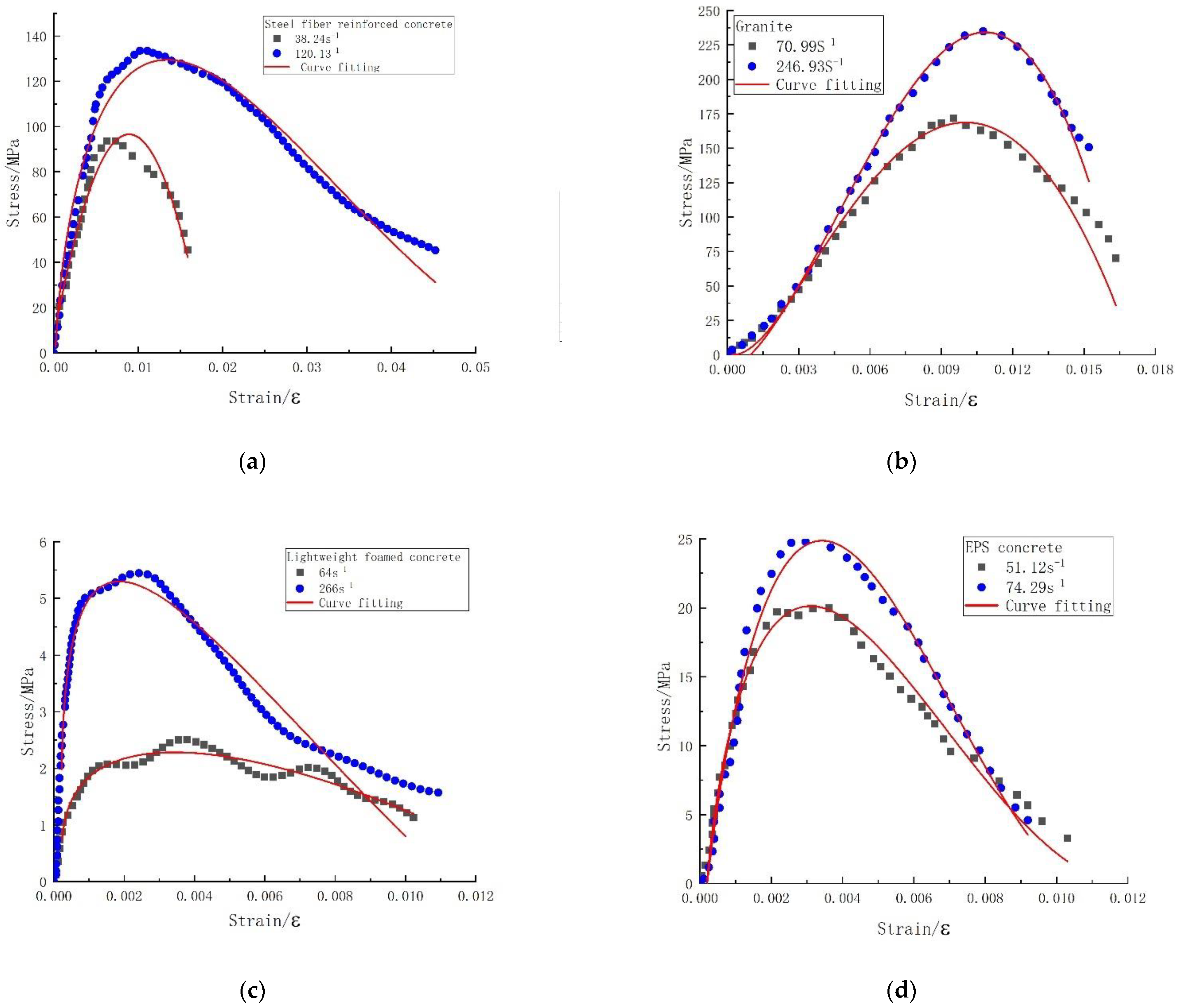
4. Validation of the Viscoelastic Constitutive Model with Damage

In this paper, Formula (9) was used to fit the stress–strain curves of coal rock and foam concrete under different strain rates, and the 1stOpt program was used to realize the calculation. The coal-rock fitting curve is shown in Figure 15, the foam concrete fitting curve is shown in Figure 16, and the specific parameters obtained are shown in Table 3.
Ye et al. [30] obtained the stress–strain curves of steel fiber-reinforced concrete at different strain rates by SHPB. Cai et al. [31] studied the dynamic mechanical properties of granite. Feng et al. [32] studied the dynamic mechanical properties of lightweight foamed concrete. Li et al. [33] studied the impact properties of EPS concrete. In order to further verify the correctness of the constitutive model, this paper cites the experimental data of the above scholars. In this paper, Formula (9) was used to fit the stress–strain curves of steel fiber-reinforced concrete, granite, lightweight foam concrete, and EPS concrete at different strain rates, the 1stOpt program was used to realize the calculation, and the fitting curve is shown in Figure 17. The specific parameters obtained are shown in Table 2. It can be seen from Table 2 that the fitting degree R2 was greater than 0.9, indicating that the constitutive equation established in this paper has wide applicability. 1stOpt is a mathematical optimization analysis synthesis tool developed by 7D-Soft High Technology Inc. in China, which is widely used in the fields of nonlinear regression, curve fitting, and nonlinear complex engineering mode parameter evaluation solutions, etc. The data in the references in this paper were extracted by GetData.
The parameter A is a constant in the principal structure model established in this paper, and determines the magnitudes of the parameters Ea and E2. The parameter alpha and the parameter beta jointly determine the trend of the whole curve. The parameter alpha has a greater influence on the peak strain and peak stress of the curve. The parameter beta has a greater influence on the direction of the opening of the curve. The parameter Ea is determined by the rising section of the curve, and E2 is determined by the falling section of the curve. The intrinsic constitutive model established in this paper also has certain defects, for example, the model was only able to describe the large trend of stress–strain, and it could not accurately describe the curve wavy fluctuation. The description of material strength and weakness by the intrinsic constitutive model is described by Ea and E2. Due to the limited experimental data, the model could only prove to be valid for a certain range of material strengths at present.

5. Conclusions

(a) In this paper, the ZWT constitutive model was simplified to only four parameters according to the dynamic characteristics. In this paper, the scope of application of the constitutive model was expanded by introducing damage factors and correction coefficients, and a constitutive model with only seven parameters was established.
(b) In this paper, the effect of damage on the dynamic load strength of materials under the action of all was considered, the damage theory was introduced into the ZWT intrinsic structure model, the stress–strain curves of a variety of materials were fitted using the improved damage-type viscoelastic intrinsic structure model equations, and the fitted curves and the measured curves had a good fit line. In this paper, the established intrinsic structure model can reflect the complex dynamic mechanical properties of materials such as the strain hardening effect and strain rate strengthening effect.
(c) In this paper, kinetic experiments were conducted on coal rock and foam concrete by SHPB to obtain stress–strain curves, and stress–strain curves of steel fiber concrete, granite, lightweight foam concrete, and EPS concrete by other authors were cited. In this paper, the viscoelastic damage-type intrinsic model equations were used to fit the curves for the abovementioned materials at high strain rates, and the fitted curves were in good agreement with the measured curves. Therefore, the intrinsic constitutive model established in this paper has good applicability, thus providing a certain reference value for the study of the intrinsic constitutive relationship of materials under high-strain-rate and engineering applications.

Author Contributions

Conceptualization, X.X. and C.M.; methodology, W.L., X.X. and C.M.; validation, X.X. and W.L.; formal analysis, X.X. and C.M.; resources, X.X. and C.M.; data curation, W.L.; writing—original draft preparation, W.L.; writing—review and editing, X.X. and C.M.; visualization, W.L.; supervision, X.X. and C.M.; project administration, W.L.; funding acquisition, W.L. All authors have read and agreed to the published version of the manuscript.

Funding

This work wassupported by the Postgraduate Research & Practice Innovation Program of Jiangsu Province (KYCX22_0682) and Fundamental Research Funds for the Central Universities (Student Projects).

Institutional Review Board Statement

Not applicable.

Informed Consent Statement

Not applicable.

Data Availability Statement

Not applicable.

Acknowledgments

The author would like to gratefully acknowledge Associate Research Fellow Xiangyun Xu and Chaomin Mu for his guidance. The authors also thank Hui Zhou, Benjun Shi, and Haijian Huang for their great help in the experiments.

Conflicts of Interest

The authors declare no conflict of interest.

References

  1. Hui, C.; Cheng, C.; Shen, S.; Gao, P.; Chen, J.; Yang, J.; Zhao, M. The Effect of the Wenchuan and Lushan Earthquakes on the Size Distribution of Earthquakes along the Longmenshan Fault. Appl. Sci. 2021, 11, 8534. [Google Scholar] [CrossRef]
  2. Wei, M.; Cheng, Y.; Lin, Y.; Kuo, W.; Shu, C. Applications of dust explosion hazard and disaster prevention technology. J. Loss Prevent. Proc. 2020, 68, 104304. [Google Scholar] [CrossRef]
  3. Liu, W.; Mu, C.; Li, Z. Influence of cavity structure on gas explosion characteristics in coal mine. Powder Technol. 2022, 398, 117084. [Google Scholar] [CrossRef]
  4. Liu, W.; Xu, X.; Mu, C. Experimental Study on Two-Phase Explosion Suppression of Gas/Pulverized Coal by Explosion Suppressant. ACS Omega 2022, 7, 16644–16652. [Google Scholar] [CrossRef]
  5. Perceka, W.; Liao, W.; Wu, Y. Shear Strength Prediction Equations and Experimental Study of High Strength Steel Fiber-Reinforced Concrete Beams with Different Shear Span-to-Depth Ratios. Appl. Sci. 2019, 9, 4790. [Google Scholar] [CrossRef] [Green Version]
  6. Iskhakov, I.; Frolov, I.; Ribakov, Y. Experimental Investigation of Concrete Transverse Deformations at Relatively High Loading Rates for Interpretation of High Strength Concrete Behavior. Appl. Sci. 2021, 11, 8460. [Google Scholar] [CrossRef]
  7. He, Y.; Gao, M.; Zhao, H.; Zhao, Y.; Miguel, N.; Neves, M. Behaviour of Foam Concrete under Impact Loading Based on SHPB Experiments. Shock Vib. 2019, 2019, 2065845. [Google Scholar] [CrossRef]
  8. Li, L.; Tu, G.; Lan, C.; Liu, F. Mechanical characterization of waste-rubber-modified recycled-aggregate concrete. J. Clean. Prod. 2016, 124, 325–338. [Google Scholar] [CrossRef]
  9. Bonić, Z.; Ćurčić, G.T.; Trivunić, M.; Davidović, N.; Vatin, N. Some Methods of Protection of Concrete and Reinforcment of Reinforced-Concrete Foundations exposed to Environmental Impacts. Procedia Eng. 2015, 117, 419–430. [Google Scholar] [CrossRef] [Green Version]
  10. Belyakov, N.; Smirnova, O.; Alekseev, A.; Tan, H. Numerical Simulation of the Mechanical Behavior of Fiber-Reinforced Cement Composites Subjected Dynamic Loading. Appl. Sci. 2021, 11, 1112. [Google Scholar] [CrossRef]
  11. Thai, D.; Kim, S. Numerical simulation of pre-stressed concrete slab subjected to moderate velocity impact loading. Eng. Fail. Anal. 2017, 79, 820–835. [Google Scholar] [CrossRef]
  12. Zhao, D.; Yi, W.; Kunnath, S.K. Numerical simulation and shear resistance of reinforced concrete beams under impact. Eng. Struct. 2018, 166, 387–401. [Google Scholar] [CrossRef]
  13. Jiang, H.; Wang, X.; He, S. Numerical simulation of impact tests on reinforced concrete beams. Mater. Des. 2012, 39, 111–120. [Google Scholar] [CrossRef]
  14. Zhao, Y.; Wang, Y.; Wang, W.; Tang, L.; Liu, Q.; Cheng, G. Modeling of rheological fracture behavior of rock cracks subjected to hydraulic pressure and far field stresses. Theor. Appl. Fract. Mec. 2019, 101, 59–66. [Google Scholar] [CrossRef]
  15. Xie, S.; Lin, H.; Wang, Y.; Chen, Y.; Xiong, W.; Zhao, Y.; Du, S. A statistical damage constitutive model considering whole joint shear deformation. Int. J. Damage Mech. 2020, 29, 988–1008. [Google Scholar] [CrossRef]
  16. Yanlin, Z.; Lianyang, Z.; Weijun, W.; Wen, W.; Wenhao, M. Separation of Elastoviscoplastic Strains of Rock and a Nonlinear Creep Model. Int. J. Geomech. 2017, 18, 04017129. [Google Scholar]
  17. Luo, G.; Wu, C.; Xu, K.; Liu, L.; Chen, W. Development of dynamic constitutive model of epoxy resin considering temperature and strain rate effects using experimental methods. Mech. Mater. 2021, 159, 103887. [Google Scholar] [CrossRef]
  18. Liu, H.T.; Chen, N.; Sun, Y.Z. Experimental and Modelling of Constitutive Equation of Polycarbonate Material. Key Eng. Mater. 2015, 667, 286–291. [Google Scholar] [CrossRef]
  19. Xu, X.; Gao, S.; Zhang, D.; Niu, S.; Jin, L.; Ou, Z. Mechanical behavior of liquid nitrile rubber-modified epoxy resin: Experiments, constitutive model and application. Int. J. Mech. Sci. 2019, 151, 46–60. [Google Scholar] [CrossRef]
  20. Zhang, H.; Wang, B.; Xie, A.; Qi, Y. Experimental study on dynamic mechanical properties and constitutive model of basalt fiber reinforced concrete. Constr. Build. Mater. 2017, 152, 154–167. [Google Scholar] [CrossRef]
  21. Zhang, H.; Wang, L.; Zheng, K.; Bakura, T.J.; Totakhil, P.G. Research on compressive impact dynamic behavior and constitutive model of polypropylene fiber reinforced concrete. Constr. Build. Mater. 2018, 187, 584–595. [Google Scholar] [CrossRef]
  22. Li, B.; Zhu, Z.; Ning, J.; Li, T.; Zhou, Z. Viscoelastic–plastic constitutive model with damage of frozen soil under impact loading and freeze–thaw loading. Int. J. Mech. Sci. 2022, 214, 106890. [Google Scholar] [CrossRef]
  23. Ma, D.; Ma, Q.; Yuan, P. SHPB tests and dynamic constitutive model of artificial frozen sandy clay under confining pressure and temperature state. Cold Reg. Sci. Technol. 2017, 136, 37–43. [Google Scholar] [CrossRef]
  24. Fu, T.; Zhu, Z.; Zhang, D.; Liu, Z.; Xie, Q. Research on damage viscoelastic dynamic constitutive model of frozen soil. Cold Reg. Sci. Technol. 2019, 160, 209–221. [Google Scholar] [CrossRef]
  25. Zhang, F.; Zhu, Z.; Fu, T.; Jia, J. Damage mechanism and dynamic constitutive model of frozen soil under uniaxial impact loading. Mech. Mater. 2020, 140, 103217. [Google Scholar] [CrossRef]
  26. Wenqing, Z.; Chaomin, M.; Zhongqing, L. Study on dynamic mechanical properties of coal under impact loading. Coal Sci. Technol. 2019, 47, 198–204. [Google Scholar]
  27. Song Li, H.S. Two-wave and three-wave method in SHPB data processing. Explos. Shock Waves 2005, 25, 368–373. [Google Scholar]
  28. Lok, T.S.; Li, X.B.; Liu, D.; Zhao, P.J. Testing and Response of Large Diameter Brittle Materials Subjected to High Strain Rate. J. Mater. Civ. Eng. 2002, 14, 262–269. [Google Scholar] [CrossRef]
  29. Wang, T.T.; Shang, B. Three-Wave Mutual-Checking Method for Data Processing of SHPB Experiments of Concrete. J. Mech. 2014, 30, N5–N10. [Google Scholar] [CrossRef]
  30. Ye, Z.B.; Huang, R.Y.; Li, Y.C.; Lv, L.; Zhao, K.; Zhang, Y.L.; Ma, J.; Lin, J.J. Steel fiber-reinforced concrete under impact loading dynamic constitutive equation. Constr. Build. Mater. 2018, 190, 1049–1055. [Google Scholar] [CrossRef]
  31. Cai, Y.; Yu, S.; Lu, Y. Experimental study on granite and the determination of its true strain-rate effect. Lat. Am. J. Solids Strut. 2015, 12, 675–694. [Google Scholar] [CrossRef] [Green Version]
  32. Feng, S.; Zhou, Y.; Wang, Y.; Lei, M. Experimental research on the dynamic mechanical properties and damage characteristics of lightweight foamed concrete under impact loading. Int. J. Impact Eng. 2020, 140, 103558. [Google Scholar] [CrossRef]
  33. Li, Z.; Chen, W.; Hao, H.; Khan, M.Z.N.; Pham, T.M. Dynamic compressive properties of novel lightweight ambient-cured EPS geopolymer composite. Constr. Build. Mater. 2021, 273, 122044. [Google Scholar] [CrossRef]
Figure 1. The “Zhu–Wang–Tang” constitutive model.
Applsci 12 08407 g001
Figure 2. The “Zhu–Wang–Tang” model simplified.
Applsci 12 08407 g002
Figure 3. Equivalent constitutive model.
Applsci 12 08407 g003
Figure 4. Drilling of raw coal test pieces.
Applsci 12 08407 g004
Figure 5. Raw coal test pieces.
Applsci 12 08407 g005
Figure 6. Foam concrete specimen.
Applsci 12 08407 g006
Figure 7. Diagram of the experimental setup.
Applsci 12 08407 g007
Figure 8. Power system.
Applsci 12 08407 g008
Figure 9. Semiconductor strain gauge.
Applsci 12 08407 g009
Figure 10. DHHP-20 ultra-dynamic strain gauge.
Applsci 12 08407 g010
Figure 11. Stress wave data analysis and processing software.
Applsci 12 08407 g011
Figure 12. Dynamic stress balance verification.
Applsci 12 08407 g012
Figure 13. Coal rock stress–strain curve.
Applsci 12 08407 g013
Figure 14. Stress–strain curve of foam concrete.
Applsci 12 08407 g014
Figure 15. Coal rock fitting curve.
Applsci 12 08407 g015
Figure 16. Foam concrete fitting curve.
Applsci 12 08407 g016
Figure 17. Curve fitting. (a) Steel fiber reinforced concrete; (b) Granite; (c) Lightweight foramed concrete; (d) EPS concrete.
Applsci 12 08407 g017
Table 1. Materials used and their descriptions.
CementPO42.5 ordinary Portland cement (PC) with a density of 3150 kg/m3, an initial setting time of 50 min, and a final setting time of 3 h and 30 min
Fly ashFly ash with an average grain diameter of 1–15 μm, class I parameters, and a density of 2400 kg/m3
WaterTap water
Polypropylene fibersDensity of 0.91 g/m3, Elastic Modulus of 5000 MPa
AdmixtureHtq-1 compound foaming agent
Foam AgentCalcium stearate (C36H70CaO4)
Table 2. Mixing design for foam concrete with different densities (per m3).
Design Plastic Density (kg/m3)Fly Ash (kg)Water (kg)Cement (kg)Cement TypeFoam Agent (kg)
658164329658PC5.57
Table 3. Fitted curve parameters.
ε ·   AαβEaE2θ2δR2
Coal rock1203−0.6−1−1.77042 × 10101.77042 × 10103−0.00020.9648
1453−0.59−1−2.76368 × 10102.76368 × 10103−0.00020.9401
1863−0.545−1−2.1608 × 10102.1608 × 10103−0.00020.9584
2123−0.51−1−1.5297 × 10101.5297 × 10103−0.00020.9739
Foamed concrete156.4730.800.303005.86−3005.9330.00020.9953
235.2930.680.2012,479.65−12,479.8230.00020.9945
254.1230.640.3014,062.01−14,062.273−0.00020.9946
298.8230.500.2588,387.15−88,388.4630.00020.9946
342.9430.700.3521,752.35−21,752.573−0.00020.9881
Steel fiber-reinforced concrete38.243−0.485−1−2.58732 × 1082.58731 × 1083−0.00020.9625
120.133−0.14−0.23.84645 × 108−3.84677 × 1083−0.00020.9712
Granite70.993−0.27−0.47−2.77818 × 1092.77818 × 1093−0.00020.9583
246.9330.020.332.18859 × 1010−2.18859 × 10103−0.00020.9943
Lightweight foamed concrete643−0.0026−0.7155,087.9264−155,093.6363−0.00020.9078
2663−0.34−0.75.30233 × 107−5.30245 × 1073−0.00020.9105
EPS concrete51.123−0.0770.06−2.97949 × 1092.9796 × 1093−0.00020.9776
74.2930.10.5−1.00786 × 1091.00788 × 1093−0.00020.9838
Publisher’s Note: MDPI stays neutral with regard to jurisdictional claims in published maps and institutional affiliations.

