
Numerical Study of the Impact of Shot Peening on the Tooth Root Fatigue Performances of Gears Using Critical Plane Fatigue Criteria


Faculty of Science and Technology, Free University of Bolzano/Bozen 1, 39100 Bolzano, Italy
Appl. Sci. 2022, 12(16), 8245; https://doi.org/10.3390/app12168245
Submission received: 19 July 2022
/
Revised: 8 August 2022
/
Accepted: 10 August 2022
/
Published: 18 August 2022
(This article belongs to the Topic Fatigue and Fracture Assessment of Structural Components and Materials)
Abstract
:Gears are one of the the most widespread mechanical components and their design is supported by standard calculation methods. Among all the possible failure modes of gears, tooth root bending is the most critical and could lead to catastrophic failures. In this regard, different surface treatments could be exploited to improve the gear strength. Among them, shot peening is the most common. The aim of this study is to evaluate the effectiveness of shot peening on improving the tooth root bending resistance. This is achieved by exploiting the Finite Element Method (FEM) in combination with advanced multiaxial fatigue criterion based on the critical plane concept. A standard Single Tooth Bending Fatigue test was reproduced numerically via FEM. Beside the wrought gears, shot peened ones were also simulated. The state of stress induced by the shot peening was obtained numerically by simulating the surface treatment itself with non-linear dynamic analyses. The results have shown quantitatively how the residual stresses promote an improvement in the resistance and how the local hardening could lead to different early paths of nucleation and propagation of cracks on the tooth fillet.
1. Introduction
Gears are mechanical components aimed at transmitting mechanical power [1]. The torque is transferred via the mesh of two teeth. These could typically fail due to different failure modes [2,3,4]. In the presence of high contact pressures and poor lubrication, the sliding–rolling contact between the flanks usually lead to wear [5], scuffing [6], pitting [7,8] or micropitting [9].
In addition, the meshing of the flanks induces pulsating stresses at the tooth root fillet [10,11]. Failures due to tooth root bending could lead to catastrophic consequences: while other failure modes foresee a progressive deterioration of gear performance with increasing noise, vibration and loss of positioning accuracy (increasing transmission error), the failure due to tooth root bending occurs instantaneously without notice. The high periodic stresses promote the nucleation of surface cracks. Once nucleated, the cracks propagate below the surface. Once the resistant area is no longer capable of withstanding the load, an instantaneous detachment of the tooth occurs. This failure mode is usually referred as Tooth (Root) Bending Fatigue (TBF) [12].
In the gear industry, the Tooth Bending Strength (TBS) is the main design criterion [13,14]. TBS is usually evaluated using standards. Specifically, the most used ones are the ISO 6336-3 [13] and the AGMA 2001 [15]. Both prescribe simplified methods to evaluate the actual stress in the tooth root region and provide tabulated data for the maximum permissible stress the most common materials can withstand. However, according to ISO 6336-5 [13], for unusual materials and special treatments, has to be estimated experimentally. The permissible stress directly depends on the fatigue limit of the material . Its determination can relay on different typologies of tests. The most common ones are the Meshing Gears (MG) test, e.g., [14,16], the Single Tooth Bending Fatigue (STBF) test, e.g., [17,18,19] and the tests on notched specimens, e.g., [20,21,22]. In the meshing gears experiments, the specimen is a gear pair manufactured with the material to be characterized. Surface treatments could also be applied. This kind of test reproduces the real loading conditions under operation. The stress cycle in the root region reflects the one that real gears will be subjected to during operation [23,24]. While this configuration is possibly the one offering the most reliable results, it is time-consuming and expensive. With each gear pair, a single value of can be estimated since the test ends with the breakage of (at least) one tooth rendering the specimen unusable for further tests. The testing costs can be significantly reduced using notched specimens instead of meshing gears.
While the testing of simple notched samples could be performed on any monoaxial testing device, the absence of meshing limits the reliability of the results that did not include some important influences, e.g., the effect of the manufacturing process, the real surface finishing, the lubrication, etc. To partially counteract this limitation, opportune correction coefficients are used [25]. While this practice could slightly improve the results, they remain far from being as reliable as those obtained with tests on meshing gears. A compromise solution is represented by the Single Tooth Bending Fatigue (STBF) test [17].
STBF relies on the application of two time-dependent coaxial forces to two opposite flanks of teeth of the gear sample. The application of the forces uses two anvils and the Wildhaber distance [1] to ensure equilibrium of the system. This configuration uses (for each test) only two teeth in which final failure does not compromise the entire gear and another teeth pair of the same gear could be used for the successive test. In other words, with the STBF approach, multiple tests could be performed on a single gear (instead of a single test every two gears like in the MG approach). Moreover, STBF tests do not require lubrication thus resulting in low-cost and simple experimentation [26]. While these tests seem to be the best experimental configuration, some problems could arise when the measures in terms of forces have to be converted into the fatigue limit of the material . In most cases, this is achieved with an inverse application of the standards. However, this requires the re-definition of some parameters with the consequent introduction of uncertainties. For this reason, in this study, instead of relay on the standards, Finite Element Simulations of the STBF configuration have been used to determine the stress tensor and how it varies during the loading cycle. Subsequently, a multiaxial fatigue criterion, i.e., the Findlay one [27], was used to relate the force applied during the test and the fatigue limit. In this way, it is possible for a given material and a given gear geometry, to determine the level of force that will theoretically lead to the failure of the sample in cycles. By way of example, the gear geometry according to [18] was used, but the procedure could be generally applied to any gear geometry. The previously determined level of force was successively applied to the same gears which were, however, shot peened before the fatigue tests. The residual stresses induced by the shot peening have been determined with a non-linear dynamic simulation of the surface treatment itself. The pre-conditioned samples were virtually tested in accordance to the wrought gears (not peened) applying the level of force obtained before. The FEM results were analysed with the same approach exploiting the Findley criterion. The comparison of the equivalent stress (or better called damage parameter DP) for the wrought and the shot peened gear allowed the quantification of the impact of shot peening on the tooth root bending resistance. Moreover, the high level of detail of the simulations (meshing size of 10 μm), has allowed us to relate the slight shift of the crack nucleation position and orientation to the non-homogeneous residual stress field induced by the shot peening treatment.
2. Materials and Methods
2.1. Finite Element Simulations
In the present paper, the gear geometry according to [18] was simulated in the STBF conditions Table 1.
The material of the gears was considered to be a 34Cr4 steel having the mechanical properties [28] summarized in Table 2. While under operation the external loads did not produce any plastic deformation, the shot peening process induces a compressive residual-stress state in sub-surface region. Consequently, the stress–strain relation was modelled having an initial elastic part ( GPa) and a second plastic part. The hardening was modelled via the Voce equation.
All the FEM simulations were performed in the open source environment Salome—Meca Code_Aster.
2.1.1. Shot Peening
Before running the simulation of the fatigue tests, a numerical simulation of the shot peening process was performed.
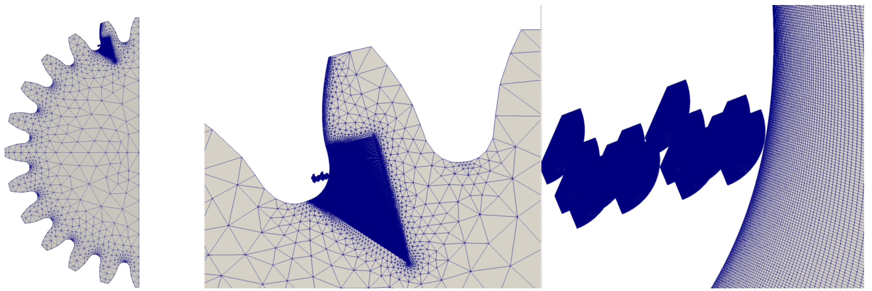
Simulating the shot peening process is a very challenging task that involves dynamic analysis of moving parts (the shots—which have been modelled as rigid in the present study) impacting the metallic component to be shot peened. The number of parameters that will affect the shot peening results is quite high and frequently concealed by the industrial secrets of the manufacturer. The most relevant parameters include the size of the spheres, their density, the shooting velocity, the angle of impact, the hardness, the level of coverage, etc. By acting on these parameters, it is possible to affect the properties of the shot-peened component such as the initial yield stress, the work-hardening characteristics, the surface hardness, strain-rate dependence, etc. In order to gain better control over the residual stresses after peening, it is important to establish a relationship between these parameters and residual stress characteristics. In the past, this was achieved with empirical relations only, based on experimental evidence. Nowadays, with the increasing computational resources, the numerical approaches to this problem are becoming increasingly widespread (Figure 1).
Considering that measuring the residual stresses could be very time demanding, establishing a relationship between the shot peening parameters and the induced stress fields would require an immense effort. In this regard, the Finite Element Method (FEM) represents a valid and more effective alternative to better understand this relationship. The impact of the shoot peens having a high velocity and double non-linearity of the problem (related on the one side to the contact of two bodies and on the other side of the elastic–plastic behaviour of the material) can be easily included in a unique numerical model capable of precisely determining the residual stress field for that configuration. Hardy et al. [29] was among the first to simulate the problem of a rigid body indenting an elastic–perfect plastic plate via FEM. An example of analysis exploiting a commercial FE software was shown by Edberg et al. [30]. Edberg et al. simulated the impact of a single sphere on visco-plastic and elasto-plastic materials. However, the combinations of parameters analysed did not represent the typical range used in modern shot peening treatments. More complete studies were performed in the late 90s by Al-Hassani [31] and Guagliano et al. [32]. Other examples of Finite Element simulations of shot peening considering the deformability of the shots were performed by Deslaef and Rouhaud [33,34]. In their studies, Deslaef and Rouhaud highlighted the poor accuracy in predicting the stress strain field of the empirical models. Another paper dealing with shot peening and its simulation with FEM was published by Meguid et al. [35,36]. They conducted a dynamic FE analysis of single and multiple shot impacts, investigating the effect of some shot and target parameters.
While a numerical approach provides an effective way for quantitatively determining relationships between shot and target parameters and residual stress characteristics, it cannot model a full stream of shots without an unmanageable computation effort. Some scholars [20,31,32,34,36] simulated multiple impacts, but not a realistic stream of shots: the pattern was specified a priori while the interaction between the spheres was not taken into consideration. Alternatively to FE, the Discrete Element Method (DEM) could be employed for the modelling of the shoot peening [37]. Some scholars demonstrated the possibility of combining FEM and DEM [38]. In the latter, the interaction between the spheres was extensively studied. Numerical studies dealing with the impact of the shot diameter, the friction and sphere size were studied by different scholars [39,40,41].
The shot impact locations were thus assumed a priori and the stream of shots was not modelled. In the present paper, the shot peening process was computationally modelled assuming a random (a priori) distribution of the shots. The shots were modelled as infinitely rigid. Their diameter was assumed to be mm. The speed of the shots was assumed to be m/s.
For this purpose, a non-linear dynamic explicit algorithm was used. The direct method consists of solving the problem resulting from the discretization by finite elements of displacement’s formulation. The discretization of the virtual work of the inertial forces, in a field is written as:
where is the field absolute displacement, the matrix of inertia and and the vector degrees of freedom its second-order derivative. The discretization of the virtual work of the interior efforts in linear elasticity is written:
is the stiffness matrix. Lastly, designates the second member resulting from the discretization of the virtual work of the external forces.
For
accompanied by boundary conditions.
For all non-linear and dynamic analyses, incremental loads are needed. Implicit or explicit methods can be used to solve these problems. Explicit methods calculate the state of a system at a later time from the state of the system at the current time, while implicit methods find a solution by solving an equation involving both the current state of the system and the later state.
For the time integration, the centred differences were used. This is an explicit scheme. This scheme, contrary to the implicit one, is conditionally stable. In this method, the accelerations and velocities are approximated in terms of the displacements using the finite difference expressions and substituted in the equation of motion in order to solve for the displacements. The final expression for the equation of motion in terms of displacement alone was obtained as:
from which it is possible to solve for .
The initial time step was set to s but, during the simulation, it was reduced up to s. The simulation was stopped after s when all the spheres had hit the surface.
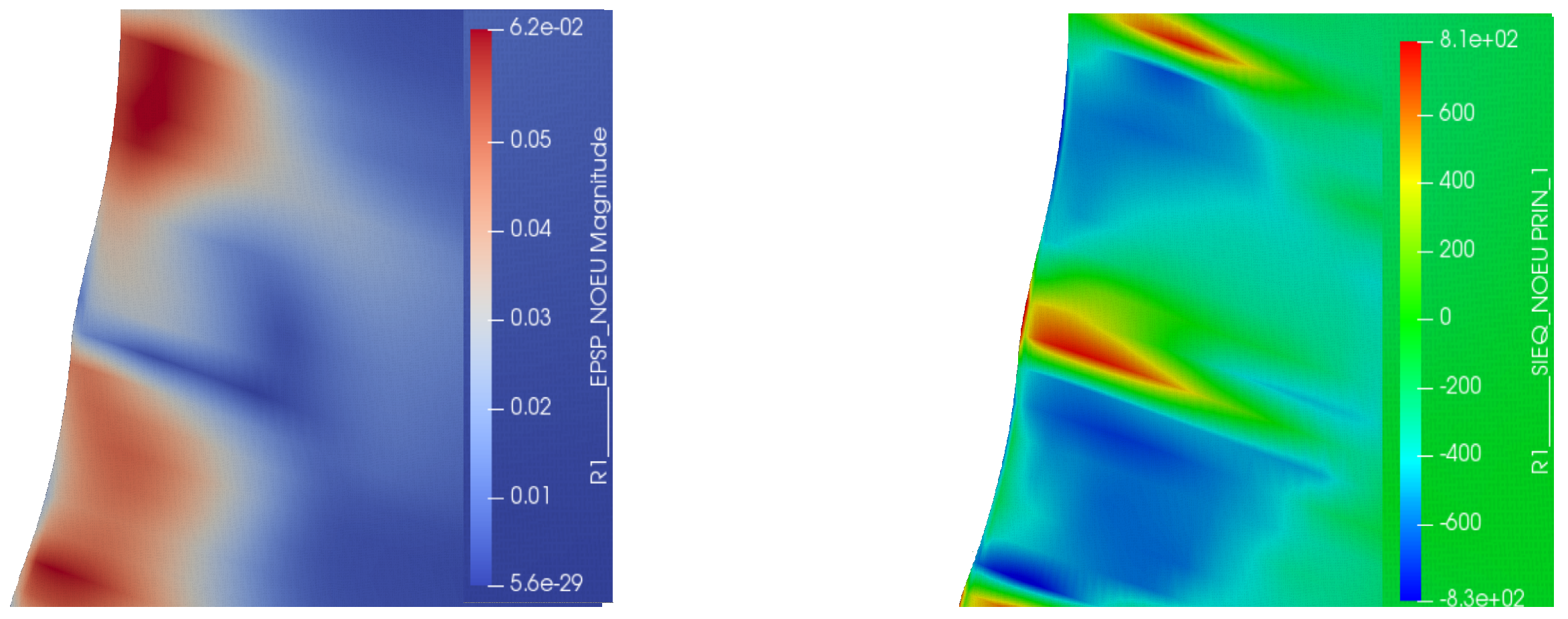
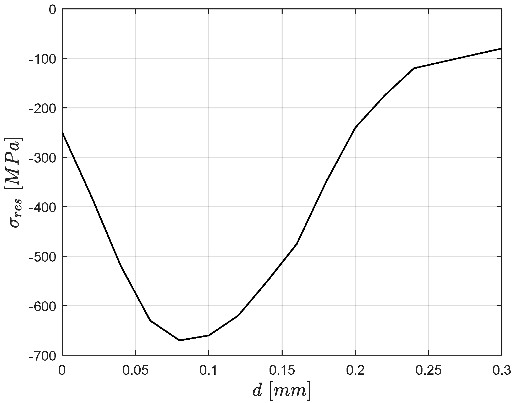
Through the finite element method, the elastic–plastic dynamic process of shot peening on the gear-sample was simulated. The residual stress distribution and the corresponding plastic deformations within the target region, namely the tooth root fillet, are shown in Figure 2. Figure 3 shows the residual stress profile in the radial direction starting from the surface. The values are aligned with the typical ones for shot-peened gears [42].
2.1.2. STBF Test
In order to simplify the model and speed up the calculation, differently from [23], it was decided to directly apply the forces on the gear instead of modelling the anvil–gear contacts. This assumption could be made considering that the aim of the simulation is to study the stress state in the root region only and slight deformations of the flank will not affect the results. Moreover, only a section of the system, relying on its symmetry was modelled. The same tooth root meshing techniques adopted by Benedetti et al. [18] were used to increase the mesh quality in the fillet region.
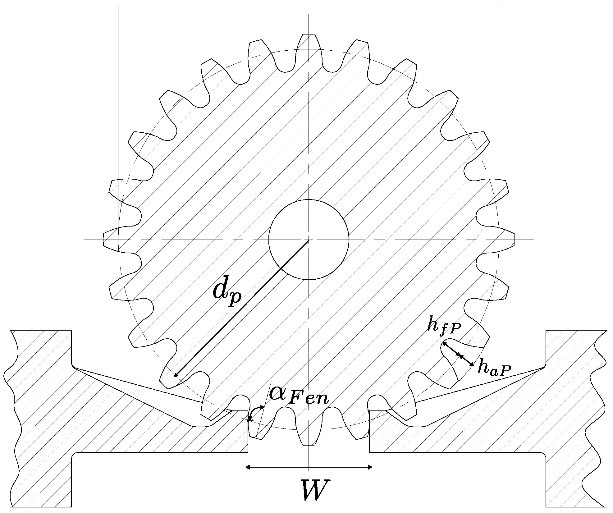
STBF tests are widely exploited in the technical and scientific literature thanks to their simplicity and low cost. Many references can be found in the literature dealing with STBF tests [8,11,18,19,25,43,44,45,46,47,48,49,50,51,52,53,54,55]. The results of STBF tests should be used in combination with standards (e.g., [13]) for the design of new gears. However, the inverse application of the standards to convert the experimental data into material properties to be used for designing new gears , foresees the necessity to re-define some geometrical parameters; the standard, in fact, is applicable to meshing gears only. STBF tests differ from meshing gears for the following reasons [23]: (1) the point of application of the load did not change; (2) the load did not oscillate from zero to the maximum value, but in the range 10–100% of the maximum. In STBF (Figure 4) tests, in fact, to avoid undesired displacement of the gear, a minimum compressive load is necessarily present. This reflects on the stress history. In the STBF tests, the loads act with a fixed direction varying in a sinusoidal manner with a constant amplitude. This reflects on the angle between the force and the normal to the loaded tooth axis , which did not change during the tests and can potentially be different from the one in the Outer Point of Single pair tooth Contact considered in the standard. These differences influence the share between pure bending and pure compressive stresses (neglected by the standard). In running gears, despite the angle between the force and the loaded tooth axis, the position of the contact also moves along the tooth flank during engagement. These circumstances lead to very different stress histories. The most reliable and effective method to take into account all these differences, is to use advanced fatigue criteria. This procedure was already used by the authors for determining the relation between STBF tests and real gears [23,56,57,58,59].
2.2. Fatigue Criteria
Generally speaking, the determination of the fatigue performances of mechanical components under multiaxial loads is challenging. Several scholars have proposed plenty of fatigue criteria [27,60,61,62,63,64,65,66].
The most advanced model relies on the critical plane concept. The fatigue failure is assumed to nucleate on the plane where both the normal and the shear stress components are considered critical. While the application of such advanced methods is already infrequent due to the need of certain coding to determine all the required parameters, their application to gears is very rare.
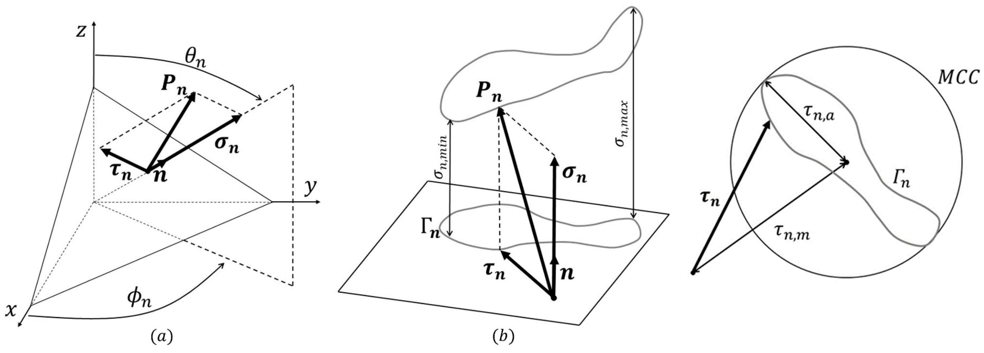
Ref. [67] shows the application of such methods to hypoid gears combining the Liu and Mahadevan criterion [68] and an FEM. In [69], the Crossland fatigue criterion [61] was exploited to evaluate the state of stress in spur gears. In the present work, among all the available criteria, the Findley one was applied. The stress exerted on a plane defined by a normal vector , having (spherical) coordinates and , is defined by the vector characterized by both modulus and direction varying in time. The vector can be written as
has normal component , which varies in modulus but is characterized by a fixed direction, and a tangential one () having both time-varying modulus and direction. In the particular case where the stresses are periodic, the vertex of describes a closed curve, whose minimum and maximum distance from the plane could be identified as and , respectively. The projection of the curve into the plane, defines the two-dimensional curve (Figure 5).
The stress history can be obtained via the time-dependant FEM simulations where the entire loading–unloading cycle is simulated in 20 discrete steps (applying a force varying from to N). The stress tensor history (a symmetric matrix showed in Equation (1)) must be extracted for each point where fracture could nucleate, i.e., each point within the root fillet region for both the FE analyses. Thus, through the numerical analysis, it is possible to obtain the stress tensor of all points belonging to the tooth root region (namely the most critical area). These are analysed with the fatigue criterion according to Findley which also considers non-proportional loads.
Through the geometrical properties of the curve , the alternate and the average components of the tangential stress could be determined. Several methods observe this scope. The most used one is the so called Minimum Circumscribing Circle Method (MCC) [70]. is assumed equal to the radius of the smallest circle that entirely contains the curve , equal to the distance between the centre of the MCC and the origin (Figure 5).
For each plane with a generic orientation, the shear stress amplitude and the maximum normal stress should be carefully evaluated. The critical plane is determined, among all the possible planes having generic orientations, as the one where the damage parameter results maximum (Equation (7)). The damage parameter summarizes the severity of a stress cycle. It has to be compared with the fatigue limit of the material f as with any other equivalent stress (e.g., Sines, Gough–Pollard). Its units are MPa. However, instead of just combining some of the stress components of the stress tensor, the damage parameter is not only a function of the stress state, but also depends on the material through the parameter k. For the present steel .
It can be iteratively determined varying and in the range . The damage parameter can be determined according to Equation (7).
k is a constant factor that takes into account the different responses regarding propagation of the fatigue crack when subjected to bending or torsion. f is the fatigue limit of the material. Ductile materials show small k. Both parameters can be calculated as a function of the symmetrical alternating-bending-loading fatigue limit , and the symmetrical alternating-torsional-loading fatigue limit (Equation (8)).
Applying the fatigue criterion, it is possible to determine on each point of the tooth root (where data on could be extracted from the FEM analysis).
3. Results Furthermore, Discussion
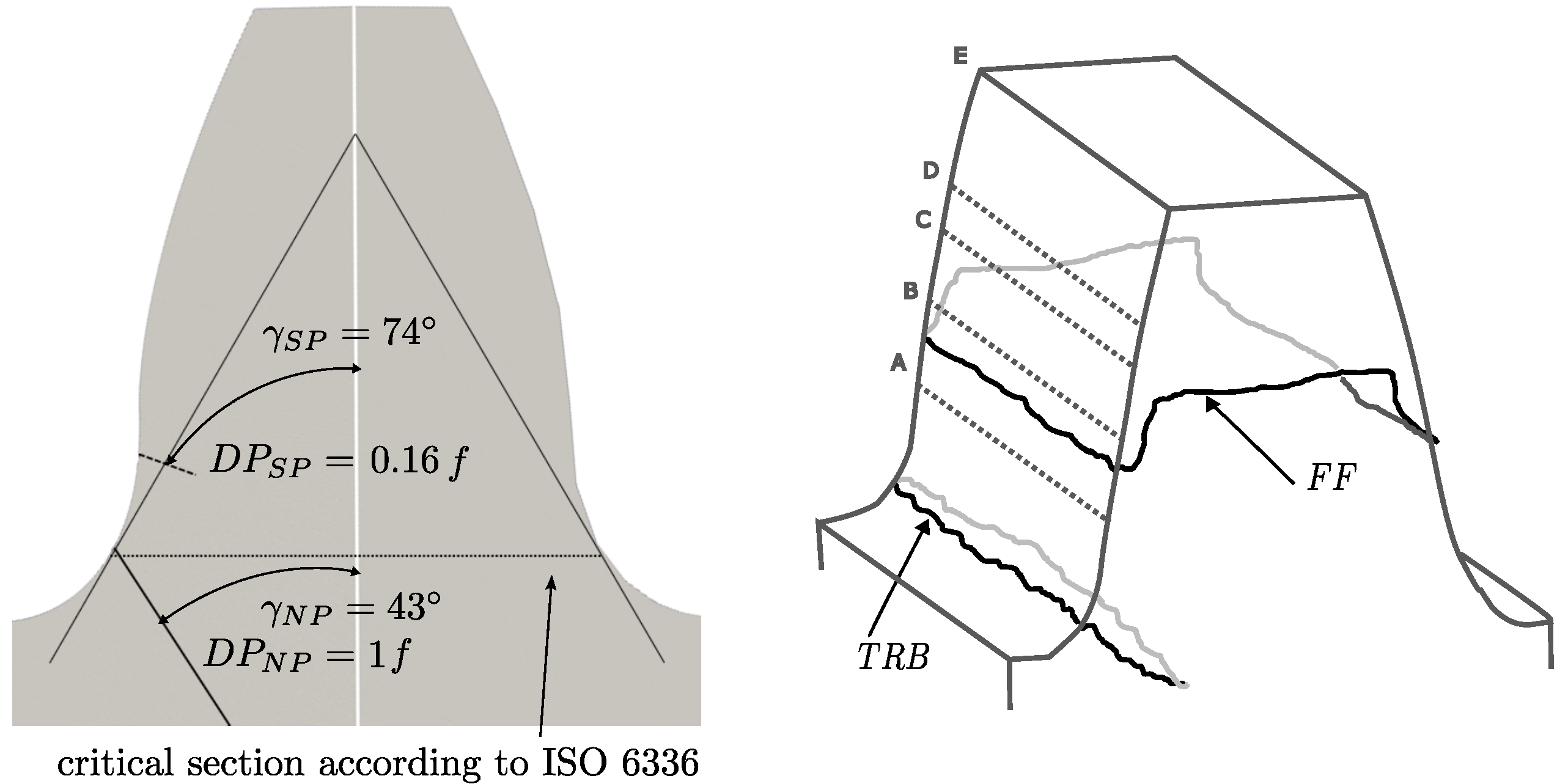
In the present work, the effect of shoot peening on the tooth root fatigue resistance of gears has been studied via Finite Element Simulations in combination with the Findley fatigue criterion. The gear geometry is the standard geometry used for the majority of experimental tests on gears (STBF). The loading cycle and the corresponding time-dependent stress state in the tooth root region were obtained with non-linear FE simulations where the STBF configuration was reproduced. A reference case without shot peening was simulated in the wrought condition. In a second model, the residual stress state induced by a shot peening process ( mm, m/s) was simulated with a separate pre-conditioning simulation and successively subjected to the same loading cycle as the reference non-treated gear. The most critical point and the severity of the damage were evaluated for both conditions exploiting the Findley fatigue criterion (Figure 6).
The results for the reference non-treated gear are coherent with the experimental findings [57] showing a nucleation site in the “critical section” as defined by the ISO standard and with an early propagation direction of . The shot-peened gear shows quite a different behaviour. The nucleation position lies significantly above the “critical section” and the early propagation direction results in (angle between the propagation direction and the tooth axis). This difference could be justified by the residual compression state which reduces the maximum normal stresses in the fillet region (the one that was shot-peened). In this regard, the damage parameter result was about 5.9 times lower with respect to the reference gear ( vs. ). The most critical region, is therefore not in the fillet, but slightly above, where, despite a bigger section-to-bending ratio, the loading history results were more critical than in the fillet area where the compressive stresses mitigate the stress peaks. The authors are not aware of available data in terms of crack position for shot-peened gears. However, the phenomenon seems to be comparable to the effect of surface hardening. In this regard, some authors claim that the case-hardening protects the fillet leading to other failure mechanisms such flank fracture [71], which represents damage similar to the tooth tooth bending failure where cracks start far from the root. The shift of the nucleation position to a larger diameter is a typical phenomenon of the case-hardened and the nitrided gears [10] where the increased material performances in the fillet region act as the compressive residual stresses in the shot peening, protecting the material from incipient damages. A suggestion could be to extend the shot-peened area as much as possible and also outside the fillet region.
4. Conclusions
This study focuses on the development of an effective and reliable model for simulating the impact of shot peening on the tooth root bending strength of gears. The stress state induced by the shot peening process is simulated via explicit dynamic simulations using the open-source solver Code_Aster. The stress state for both the shot-peened and non-peened gear samples taken as reference have been analysed via the Findlay multiaxial fatigue criterion. As reference configuration, the STBF test, i.e., the standard procedure for the determination of the material properties in the gear sector, was employed. The simulation of the shot-peening process highlighted a compressive stress state with a peak slightly below the surface. This is the typical profile of shot-peened components. The maximum compressive stress was observed to be 660 MPa. The presence of the compressive stress state has a significant impact on the tooth-root resistance of the gear: the loading cycle in the presence of residual stresses results in significantly less severe stress (about 5.9 times). The presence of compression stresses, in fact, mitigates the positive peaks of stress leading to a less critical condition. The nucleation site, which typically lies on the critical section as defined by the ISO 6336 standard, shifted to a bigger diameter. This finding can be explained by the fact that in gears, shot peening is typically limited to the fillet region. This evidence is aligned with the failure of case-hardened and nitrided gears where the crack generates at locations on the surface that are no longer treated. This phenomenon seems to be common for shot-peened and case-hardened gears where fillet regions are protected by the residual stress state. While specific data dealing with the shift of the crack nucleation site to bigger diameters are not available for shot-peened gears, many scholars reported the failure due to another mechanism called Flank Fracture. This mechanism is similar to tooth root bending, with a crack that nucleates on the loaded flank and then propagates throughout the entire width. However, different from tooth root bending, the crack nucleated on the active part of the flank. This evidence supports the results of this study where the residual stress promotes nucleation of the crack outside the fillet region.
While the actual findings are specific for the gear geometry, material and shot-peening parameters considered in the example shown, the procedure is of general validity and can be applied to any configuration, allowing for a better understanding of the impact of shot peening on the fatigue performance of gears.
Funding
This research received no external funding.
Conflicts of Interest
The author declares no conflict of interest.
Abbreviations
The following abbreviations are used in this manuscript:
| DEM | Discrete Element Method |
| DP | Damage Parameter |
| FEM | Finite Element Model |
| MCC | Minimum Circumscribing Circle Method |
| MG | Meshing Gears |
| STBF | Single Tooth Bending Fatigue |
References
- Vullo, V. Gears; Springer: Berlin/Heidelberg, Germany, 2020. [Google Scholar]
- Concli, F.; Cortese, L.; Vidoni, R.; Nalli, F.; Carabin, G. A mixed FEM and lumped-parameter dynamic model for evaluating the modal properties of planetary gearboxes. J. Mech. Sci. Technol. 2018, 32, 3047–3056. [Google Scholar] [CrossRef]
- Yadav, A. Different types Failure in gears-A Review. Int. J. Sci. Eng. Technol. Res. 2012, 5, 82–92. [Google Scholar]
- Fernandes, P.; McDuling, C. Surface contact fatigue failures in gears. Eng. Fail. Anal. 1997, 4, 99–107. [Google Scholar] [CrossRef]
- Wu, S.; Cheng, H. Sliding wear calculation in spur gears. J. Tribol. 1993, 115, 493–500. [Google Scholar] [CrossRef]
- Li, S.; Kahraman, A. A scuffing model for spur gear contacts. Mech. Mach. Theory 2021, 156, 104161. [Google Scholar] [CrossRef]
- Concli, F. Austempered Ductile Iron (ADI) for gears: Contact and bending fatigue behavior. Procedia Struct. Integr. 2018, 8, 14–23. [Google Scholar] [CrossRef]
- Gorla, C.; Conrado, E.; Rosa, F.; Concli, F. Contact and bending fatigue behaviour of austempered ductile iron gears. Proc. Inst. Mech. Eng. Part C J. Mech. Eng. Sci. 2018, 232, 998–1008. [Google Scholar] [CrossRef]
- Liu, H.; Liu, H.; Zhu, C.; Zhou, Y. A review on micropitting studies of steel gears. Coatings 2019, 9, 42. [Google Scholar] [CrossRef]
- Gorla, C.; Rosa, F.; Conrado, E.; Concli, F. Bending fatigue strength of case carburized and nitrided gear steels for aeronautical applications. Int. J. Appl. Eng. Res. 2017, 12, 11306–11322. [Google Scholar]
- Bonaiti, L.; Concli, F.; Gorla, C.; Rosa, F. Bending fatigue behaviour of 17-4 PH gears produced via selective laser melting. Procedia Struct. Integr. 2019, 24, 764–774. [Google Scholar] [CrossRef]
- Fernandes, P. Tooth bending fatigue failures in gears. Eng. Fail. Anal. 1996, 3, 219–225. [Google Scholar] [CrossRef]
- ISO 6336-1:2006; Calculation of Load capacity of Spur and Helical Gears, Part 1. International Standard Organization: Geneva, Switzerland, 2006.
- Hong, I.J.; Kahraman, A.; Anderson, N. A rotating gear test methodology for evaluation of high-cycle tooth bending fatigue lives under fully reversed and fully released loading conditions. Int. J. Fatigue 2020, 133, 105432. [Google Scholar] [CrossRef]
- American Gear Manufacturers Association. ANSI/AGMA 2001-D04, Fundamental Rating Factors and Calculation Methods for Involute Spur and Helical Gear Teeth; American Gear Manufacturers Association: Alexandria, VA, USA, 2004. [Google Scholar]
- Rao, S.; McPherson, D. Experimental characterization of bending fatigue strength in gear teeth. Gear Technol. 2003, 20, 25–32. [Google Scholar]
- McPherson, D.R.; Rao, S.B. Methodology for translating single-tooth bending fatigue data to be comparable to running gear data. Gear Technol. 2008, 6, 42–51. [Google Scholar]
- Benedetti, M.; Fontanari, V.; Höhn, B.R.; Oster, P.; Tobie, T. Influence of shot peening on bending tooth fatigue limit of case hardened gears. Int. J. Fatigue 2002, 24, 1127–1136. [Google Scholar] [CrossRef]
- Dobler, D.I.A.; Hergesell, I.M.; Stahl, I. Increased tooth bending strength and pitting load capacity of fine-module gears. Gear Technol. 2016, 33, 48–53. [Google Scholar]
- Medlin, D.J.; Cornelissen, B.E.; Matlock, D.K.; Krauss, G.; Filar, R.J. Effect of thermal treatments and carbon potential on bending fatigue performance of SAE 4320 gear steel. SAE Trans. 1999, 108, 547–556. [Google Scholar]
- Spice, J.J.; Matlock, D.K.; Fett, G. Optimized carburized steel fatigue performance as assessed with gear and modified brugger fatigue tests. SAE Trans. 2002, 111, 589–597. [Google Scholar]
- Vilela Costa, L.; Corrêa de Oliveira, D.; Wallace, D.; Lelong, V.; Findley, K.O. Bending fatigue in low-pressure carbonitriding of steel alloys with boron and niobium additions. J. Mater. Eng. Perform. 2020, 29, 3593–3602. [Google Scholar] [CrossRef]
- Concli, F.; Fraccaroli, L.; Maccioni, L. Gear root bending strength: A new multiaxial approach to translate the results of single tooth bending fatigue tests to meshing gears. Metals 2021, 11, 863. [Google Scholar] [CrossRef]
- Bonaiti, L.; Bayoumi, A.B.M.; Concli, F.; Rosa, F.; Gorla, C. Gear root bending strength: A comparison between Single Tooth Bending Fatigue Tests and meshing gears. J. Mech. Des. 2021, 143, 103402. [Google Scholar] [CrossRef]
- Meneghetti, G.; Dengo, C.; Lo Conte, F. Bending fatigue design of case-hardened gears based on test specimens. Proc. Inst. Mech. Eng. Part C J. Mech. Eng. Sci. 2018, 232, 1953–1969. [Google Scholar] [CrossRef]
- Hong, I.; Teaford, Z.; Kahraman, A. A comparison of gear tooth bending fatigue lives from single tooth bending and rotating gear tests. Forsch. Ingenieurwesen 2021, 1–13. [Google Scholar] [CrossRef]
- Findley, W.N. A theory for the effect of mean stress on fatigue of metals under combined torsion and axial load or bending. J. Eng. Ind. 1959, 81, 301–305. [Google Scholar] [CrossRef]
- Susmel, L. On the overall accuracy of the Modified Wöhler Curve Method in estimating high-cycle multiaxial fatigue strength. Frattura Ed Integrità Strutturale 2011, 5, 5–17. [Google Scholar] [CrossRef]
- Hardy, C.; Baronet, C.; Tordion, G. The elasto-plastic indentation of a half-space by a rigid sphere. Int. J. Numer. Methods Eng. 1971, 3, 451–462. [Google Scholar] [CrossRef]
- Edberg, J.; Lindgren, L.E.; Ken-Ichiro, M. Shot peening simulated by two different finite element formulations. In Proceedings of the International Conference on Numerical Methods in Industrial Forming Processes, New York, NY, USA, 18–21 June 1995. [Google Scholar]
- Al-Hassani, S. Numerical simulation of multiple shot impact. In Proceedings of the 7th International Conference on Shot Peening, Warsaw, Poland, 28 September–1 October 1999; pp. 217–227. [Google Scholar]
- Guagliano, M.; Vergani, L.M.; Bandini, M.; Gili, F. An approach to relate the shot peening parameters to the induced residual stresses. In Proceedings of the 7th International Conference on Shot Peening (ICSP7), Warsaw, Poland, 28 September–1 October 1999; pp. 274–282. [Google Scholar]
- Deslaef, D.; Rouhaud, E.; Rasouli-Yazdi, S. 3D finite element models of shot peening processes. In Materials Science Forum; Trans Tech Publications Ltd.: Bäch, Switzerland, 2000; Volume 347, pp. 241–246. [Google Scholar]
- Rouhaud, E.; Deslaef, D. Influence of shots’ material on shot peening, a finite element model. In Materials Science Forum; Trans Tech Publications Ltd.: Bäch, Switzerland, 2002; Volume 404, pp. 153–158. [Google Scholar]
- Meguid, S.; Shagal, G.; Stranart, J.; Daly, J. Three-dimensional dynamic finite element analysis of shot-peening induced residual stresses. Finite Elem. Anal. Des. 1999, 31, 179–191. [Google Scholar] [CrossRef]
- Meguid, S.; Shagal, G.; Stranart, J. 3D FE analysis of peening of strain-rate sensitive materials using multiple impingement model. Int. J. Impact Eng. 2002, 27, 119–134. [Google Scholar] [CrossRef]
- Cundall, P.A.; Strack, O.D. A discrete numerical model for granular assemblies. Geotechnique 1979, 29, 47–65. [Google Scholar] [CrossRef]
- Han, K.; Peric, D.; Crook, A.; Owen, D. A combined finite/discrete element simulation of shot peening processes—Part I: Studies on 2D interaction laws. Eng. Comput. 2000, 17, 593–620. [Google Scholar] [CrossRef]
- Han, K.; Owen, D.; Peric, D. Combined finite/discrete element and explicit/implicit simulations of peen forming process. Eng. Comput. 2002, 19, 92–118. [Google Scholar] [CrossRef]
- Hong, T.; Ooi, J.; Shaw, B. Three-Dimensional Finite Element Analysis of Residual Stress Induced by Single/Multiple Shots Impact; Technical report, Internal Report; School of Engineering & Electronics, University of Edinburgh: Edinburgh, UK, 2005. [Google Scholar]
- Hong, T.; Ooi, J.; Shaw, B. A numerical study of the residual stress pattern from single shot impacting on a metallic component. Adv. Eng. Softw. 2008, 39, 743–756. [Google Scholar] [CrossRef]
- You, S.; Tang, J.; Zhou, W.; Zhou, W.; Zhao, J.; Chen, H. Research on calculation of contact fatigue life of rough tooth surface considering residual stress. Eng. Fail. Anal. 2022, 140, 106459. [Google Scholar] [CrossRef]
- Fontanari, V.; Molinari, A.; Marini, M.; Pahl, W.; Benedetti, M. Tooth root bending fatigue strength of high-density sintered small-module spur gears: The effect of porosity and microstructure. Metals 2019, 9, 599. [Google Scholar] [CrossRef]
- Benedetti, M.; Menapace, C. Tooth root bending fatigue strength of small-module sinter-hardened spur gears. Powder Metall. 2017, 60, 149–156. [Google Scholar] [CrossRef]
- Winkler, K.; Schurer, S.; Tobie, T.; Stahl, K. Investigations on the tooth root bending strength and the fatigue fracture characteristics of case-carburized and shot-peened gears of different sizes. Proc. Inst. Mech. Eng. Part C J. Mech. Eng. Sci. 2019, 233, 7338–7349. [Google Scholar] [CrossRef]
- Townsend, D.; Baber, B.; Nagy, A. Evaluation of High-Contact-Ratio Spur Gears with Profile Modification. 1979. Available online: https://ntrs.nasa.gov/citations/19790023433 (accessed on 7 August 2022).
- Eyercioglu, O.; Walton, D.; Dean, T. Comparative bending fatigue strength of precision forged spur gears. Proc. Inst. Mech. Eng. Part C J. Mech. Eng. Sci. 1997, 211, 293–299. [Google Scholar] [CrossRef]
- Handschuh, R.; Krantz, T.; Lerch, B.; Burke, C. Investigation of Low-Cycle Bending Fatigue of AISI 9310 Steel Spur Gears. In Proceedings of the International Design Engineering Technical Conferences and Computers and Information in Engineering Conference, Las Vegas, NV, USA, 4–7 September 2007; Volume 7, pp. 871–877. [Google Scholar] [CrossRef]
- Gasparini, G.; Mariani, U.; Gorla, C.; Filippini, M.; Rosa, F. Bending fatigue tests of helicopter case carburized gears: Influence of material, design and manufacturing parameters. In Proceedings of the American Gear Manufacturers Association (AGMA) Fall Technical Meeting, San Antonio, TX, USA, 12–14 October 2008; pp. 131–142. [Google Scholar]
- Daniewicz, S.; Moore, D. Increasing the bending fatigue resistance of spur gear teeth using a presetting process. Int. J. Fatigue 1998, 20, 537–542. [Google Scholar] [CrossRef]
- Bian, X.; Zhou, G.; Liwei; Tan, J. Investigation of bending fatigue strength limit of alloy steel gear teeth. Proc. Inst. Mech. Eng. Part C J. Mech. Eng. Sci. 2012, 226, 615–625. [Google Scholar] [CrossRef]
- Conrado, E.; Gorla, C.; Davoli, P.; Boniardi, M. A comparison of bending fatigue strength of carburized and nitrided gears for industrial applications. Eng. Fail. Anal. 2017, 78, 41–54. [Google Scholar] [CrossRef]
- Vukic, M.; Čular, I.; Mašović, R.; Vučković, K. Effect of friction on nominal stress results in a single tooth bending fatigue test. In Proceedings of the IOP Conference Series: Materials Science and Engineering, Nanjing, China, 23–25 July 2019; Volume 659. [Google Scholar] [CrossRef]
- Dobler, F.; Tobie, T.; Stahl, K. Influence of low temperatures on material properties and tooth root bending strength of case-hardened gears. In Proceedings of the International Design Engineering Technical Conferences and Computers and Information in Engineering Conference, Boston, MA, USA, 2–5 August 2015; Volume 10. [Google Scholar] [CrossRef]
- Gorla, C.; Rosa, F.; Concli, F.; Albertini, H. Bending fatigue strength of innovative gear materials for wind turbines gearboxes: Effect of surface coatings. In Proceedings of the ASME 2012 International Mechanical Engineering Congress and Exposition, Houston, TX, USA, 9–15 November 2012; Volume 7, pp. 3141–3147. [Google Scholar] [CrossRef]
- Concli, F.; Maccioni, L.; Fraccaroli, L.; Cappellini, C. Effect of Gear Design Parameters on Stress Histories Induced by Different Tooth Bending Fatigue Tests: A Numerical-Statistical Investigation. Appl. Sci. 2022, 12, 3950. [Google Scholar] [CrossRef]
- Concli, F.; Maccioni, L.; Fraccaroli, L.; Bonaiti, L. Early crack propagation in single tooth bending fatigue: Combination of finite element analysis and critical-planes fatigue criteria. Metals 2021, 11, 1871. [Google Scholar] [CrossRef]
- Concli, F.; MacCioni, L.; Bonaiti, L. Reliable gear design: Translation of the results of single tooth bending fatigue tests through the combination of numerical simulations and fatigue criteria. WIT Trans. Eng. Sci. 2021, 130, 111–122. [Google Scholar] [CrossRef]
- Concli, F.; Maccioni, L. Critical planes criteria applied to gear teeth: Which one is the most appropriate to characterize crack propagation? Proc. WIT Trans. Eng. Sci. 2021, 133, 15–25. [Google Scholar] [CrossRef]
- Gough, H.; Pollard, H. The strength of metals under combined alternating stresses. Proc. Inst. Mech. Eng. 1935, 131, 3–103. [Google Scholar] [CrossRef]
- Crossland, B. Effect of large hydrostatic pressures on the torsional fatigue strength of an alloy steel. J. Mech. Eng. Sci. 1956, 138, 12. [Google Scholar] [CrossRef]
- Sines, G. Behavior of metals under complex static and alternating stresses. Met. Fatigue 1959, 1, 145–169. [Google Scholar]
- Matake, T. An explanation on fatigue limit under combined stress. Bull. JSME 1977, 20, 257–264. [Google Scholar] [CrossRef]
- Macha, E. Mathematical models of the life to fracture for materials subject to random complex stress systems. Sci. Pap. Inst. Mater. Sci. Appl. Mech. Wroc. Tech. Univ. 1979, 41, 99. [Google Scholar]
- McDiarmid, D. Fatigue under out-of-phase biaxial stresses of different frequencies. In Multiaxial Fatigue; ASTM International: West Conshohocken, PA, USA, 1985; pp. 606–621. [Google Scholar]
- Dang Van, K. Macro-micro approach in high-cycle multiaxial fatigue. Adv. Multiaxial Fatigue 1993, 1191, 120–130. [Google Scholar]
- Hotait, M.; Kahraman, A. Estimation of bending fatigue life of hypoid gears using a multiaxial fatigue criterion. J. Mech. Des. 2013, 135, 101005. [Google Scholar]
- Liu, Y.; Mahadevan, S. Multiaxial high-cycle fatigue criterion and life prediction for metals. Int. J. Fatigue 2005, 27, 790–800. [Google Scholar] [CrossRef]
- Savaria, V.; Bridier, F.; Bocher, P. Predicting the effects of material properties gradient and residual stresses on the bending fatigue strength of induction hardened aeronautical gears. Int. J. Fatigue 2016, 85, 70–84. [Google Scholar] [CrossRef]
- Papadopoulos, I.V. Critical plane approaches in high-cycle fatigue: On the definition of the amplitude and mean value of the shear stress acting on the critical plane. Fatigue Fract. Eng. Mater. Struct. 1998, 21, 269–285. [Google Scholar] [CrossRef]
- Boiadjiev, I.; Witzig, J.; Tobie, T.; Stahl, K. Tooth flank fracture–basic principles and calculation model for a sub-surface-initiated fatigue failure mode of case-hardened gears. In Proceedings of the International Gear Conference, Lyon, France, 26–28 August 2014; pp. 670–680. [Google Scholar]
Figure 1.
Mesh: about 1M second-order wedge elements.

Figure 2.
Plastic deformation and stress state induced by the first 2 shots.

Figure 3.
Residual stresses in the radial direction d starting from the surface.

Figure 4.
STBF test configuration.

Figure 5.
(a): Components of vector in plane defined by . (b): Definition of curve that is the projection of positions of assumed in a load cycle in plane defined by or positions of assumed in a load cycle. Individuation values of maximum and minimum normal stress and definition of and according to the MCC method.

Figure 6.
Position and early nucleation direction of the cracks for the reference and the shot-peened gears. Tooth root bending (TRB) and Flank Fracture (FF) failures according to the literature.
Figure 6.
Position and early nucleation direction of the cracks for the reference and the shot-peened gears. Tooth root bending (TRB) and Flank Fracture (FF) failures according to the literature.


Table 1.
Gear geometry.
| Parameter | Symbol | Value |
|---|---|---|
| Normal module [mm] | 5 | |
| Normal pressure angle [] | 20 | |
| Number of teeth | z | 24 |
| Face width [mm] | b | 30 |
| Profile shift coefficient | 0 | |
| Dedendum coefficient | 1.25 | |
| Addendum coefficient | 1 | |
| Root radius factor | 0.38 | |
| Wildhaber | W | 3 |
| Angle STBF [] | 15 |
Table 2.
Material properties.
| Pure Bending Fatigue Limit | Pure Torsion Fatigue Limit | Ultimate Tensile Strength |
|---|---|---|
| 410 MPa | 256 MPa | 795 MPa |
Publisher’s Note: MDPI stays neutral with regard to jurisdictional claims in published maps and institutional affiliations. |
© 2022 by the author. Licensee MDPI, Basel, Switzerland. This article is an open access article distributed under the terms and conditions of the Creative Commons Attribution (CC BY) license (https://creativecommons.org/licenses/by/4.0/).
Share and Cite
MDPI and ACS Style
Concli, F. Numerical Study of the Impact of Shot Peening on the Tooth Root Fatigue Performances of Gears Using Critical Plane Fatigue Criteria. Appl. Sci. 2022, 12, 8245. https://doi.org/10.3390/app12168245
AMA Style
Concli F. Numerical Study of the Impact of Shot Peening on the Tooth Root Fatigue Performances of Gears Using Critical Plane Fatigue Criteria. Applied Sciences. 2022; 12(16):8245. https://doi.org/10.3390/app12168245
Chicago/Turabian StyleConcli, Franco. 2022. "Numerical Study of the Impact of Shot Peening on the Tooth Root Fatigue Performances of Gears Using Critical Plane Fatigue Criteria" Applied Sciences 12, no. 16: 8245. https://doi.org/10.3390/app12168245
Note that from the first issue of 2016, this journal uses article numbers instead of page numbers. See further details here.