1. Introduction
The vapor phase is generally converted into the liquid phase during condensation. The condensate accumulates on the heat transfer surface and the liquid film becomes thicker and thicker, leading to the increasing of thermal resistance and flow resistance. Peng et al. [
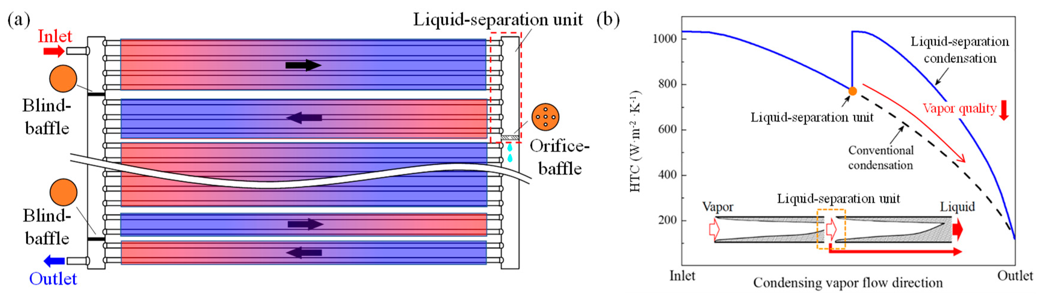
1] proposed the concept of “liquid-separation condensation” to enhance the condenser performance. The configuration of a liquid-separation condenser (LSC) is shown in
Figure 1a. The condensate can be promptly removed by the vapor-liquid separator in the headers. To deal with the alleviated mass flow rate due to the liquid drainage, the flow area should be shrunk accordingly to keep the pace of variations in mass flux. In this way, the thickness of the liquid film is largely reduced and the vapor quality is significantly improved, which finally enhances the heat transfer coefficient (HTC), as shown in
Figure 1b.
Researchers have verified the superiorities of LSC. Hua [
3] theoretically found that HTC of LSC can be 34.6% higher and the pressure drop can be 74.4% lower than the conventional condenser. Zhong et al. [
4] experimentally confirmed that when the mass flux is higher than 590 km/(m
2∙s), LSC has a higher heat transfer coefficient and 30.5–52.6% lower pressure drop, simultaneously. They further pinpointed that LSC has superior comprehensive performance in terms of penalty factor and minimum entropy generation number [
5]. Li et al. [
6] discovered that the condenser inserted with a T-junction unit can improve the heat transfer capacity by approximately 5.1%. At the level of the thermal systems, LSC also exhibits its advances in air conditioning systems, heat pump, and organic Rankine cycle (ORC). Chen et al. [
7] found that the Energy Efficiency Ratio (EER) at cooling mode and Coefficient of Performance (COP) at heating mode in an air conditioning with LSC are 9.8% and 7.3% higher than these in baseline system, respectively. They further pointed out that using LSC can reduce avoidable exergy destruction of the compressor by 45.5% [
8]. Li et al. [
6] found that the refrigeration system with LSC results in a higher COP by 6.6% compared to a conventional condenser. Chen et al. [
9] revealed that the heat pump with LSC has a higher COP and lower power consumption. Lu et al. [
10] concluded that the ORC with LSC achieves a 21.43% lower average electricity production cost than conventional ORC. In short, liquid-separation condensation is a promising technology that enables the improvement of both the condenser performance and thermal system efficiency.
As one of the essential parameters, the vapor quality (x) largely determines HTC during condensation. The higher the vapor quality is, the higher the HTC becomes. In principle, for a superior HTC in LSC, it is preferable to have a high vapor quality that is close to one after the vapor-liquid separation. Therefore, the performance of the liquid-separation unit that dominates the redistributions of vapor quality and mass flow rate is vital to LSC. More attention should be paid to the liquid-separation unit.
Up to now, only two kinds, namely the T-junction header and the orifice-baffle header, are extensively employed in LSC.
LSC with a T-junction header is based on the differential inertia force of the liquid and vapor. It was proposed by Oh et al. [
11]. Li et al. carried out a comprehensive study on this T-junction header, including a visualization experiment [
12], theoretical model [
13] and the CFD model [
14]. They found that the liquid drainage ratio (
FL) can be 100% at low inlet mass flux, and it reduces with the increasing of the inlet mass flux or inlet quality. However, in the T-junction header, the liquid and vapor can only be separated one, which limited the improvement of HTC in LSC.
Alternatively, the vapor-liquid separation in the orifice-baffle header is on the basis of gravitation force. As shown in
Figure 1, the two-phase flow from the branch inlets enters into the header where the vapor-liquid separation occurs on the orifice-baffle due to their distinct physical properties and the pressure difference across the orifices. Ideally, the liquid is accumulated on the orifice-baffle and drained out from the orifices, whereas the vapor flows out via the branch outlets. Hence, the phase separation is achieved. However, in practice, due to the intensive interactions between liquid and vapor, incomplete vapor-liquid separation occurs in the liquid-separation unit, thus limiting the potential release of liquid-separation condensation. Mo et al. [
15] pointed out that in the orifice-baffle header of LSC, the vapor-liquid separation efficiencies of annular flow and slug flow at the inlet are 45% and 80%, respectively. Li et al. [
16] established a numerical simulation model of the orifice-baffle header based on the Volume of Fluid (VOF) method. The results showed that when the diameter of the orifice is larger than 2 mm, the liquid drainage by the orifice is almost the same, and the vapor leakage rate of the orifice increases as well. The available studies on the orifice-baffle header have been simplified as one branch inlet and one branch outlet as well as only a single orifice in the center of the baffle. However, the branches and the orifices are multiple in the actual LSC [
7]. Furthermore, the mass flow rate in the header is 2–5 g/s in Li et al. [
16], which is substantially differentiated from that in LSC. The interactions between the liquid and vapor are more intensive in LSC and there exists fluid maldistribution in multiple branches. In short, the vapor-liquid separation performance and the flow characteristic in the orifice-baffle header with multiple branches and orifices under various inlet operating conditions are quite different from the existing findings. Mechanics of vapor-liquid separation and flow maldistribution in the branch are still to be unveiled, and this is in great need of further exploration.
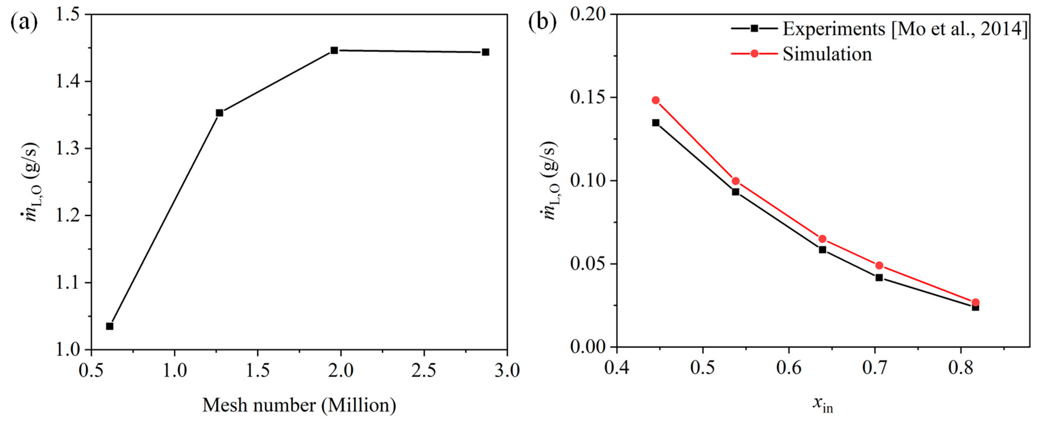
In this paper, a numerical simulation model for an orifice-baffle header with multiple branches and orifices is established and validated. The vapor-liquid separation features and the flow characteristics at various operating conditions are analyzed. This paper is of great importance to reveal the mechanisms of vapor-liquid separation and flow maldistribution.
3. Results and Discussion
In this paper, the two-phase flow characteristics in the branch outlets and orifices are comprehensively studied. The vapor-liquid separation performance and the phase distributions in the orifice are firstly investigated to obtain the vapor-liquid separation features. Then, the phase maldistributions in the branch outlet are discussed. Finally, the mechanistic model based on the force balance is established with a concern on the “droplet entrainment”.
R134a is used as the working fluid and its properties are calculated by REFPROP [
19]. The inlet operating conditions including temperature and vapor quality (
xin) are 45 °C and 0.5, respectively. To investigate its features under various conditions, the inlet mass flow rate (
ṁin) is set in the range of 9–21 g/s based on scenarios in the air conditioning.
3.1. Performance of the Header and Flow Characteristics in the Orifices
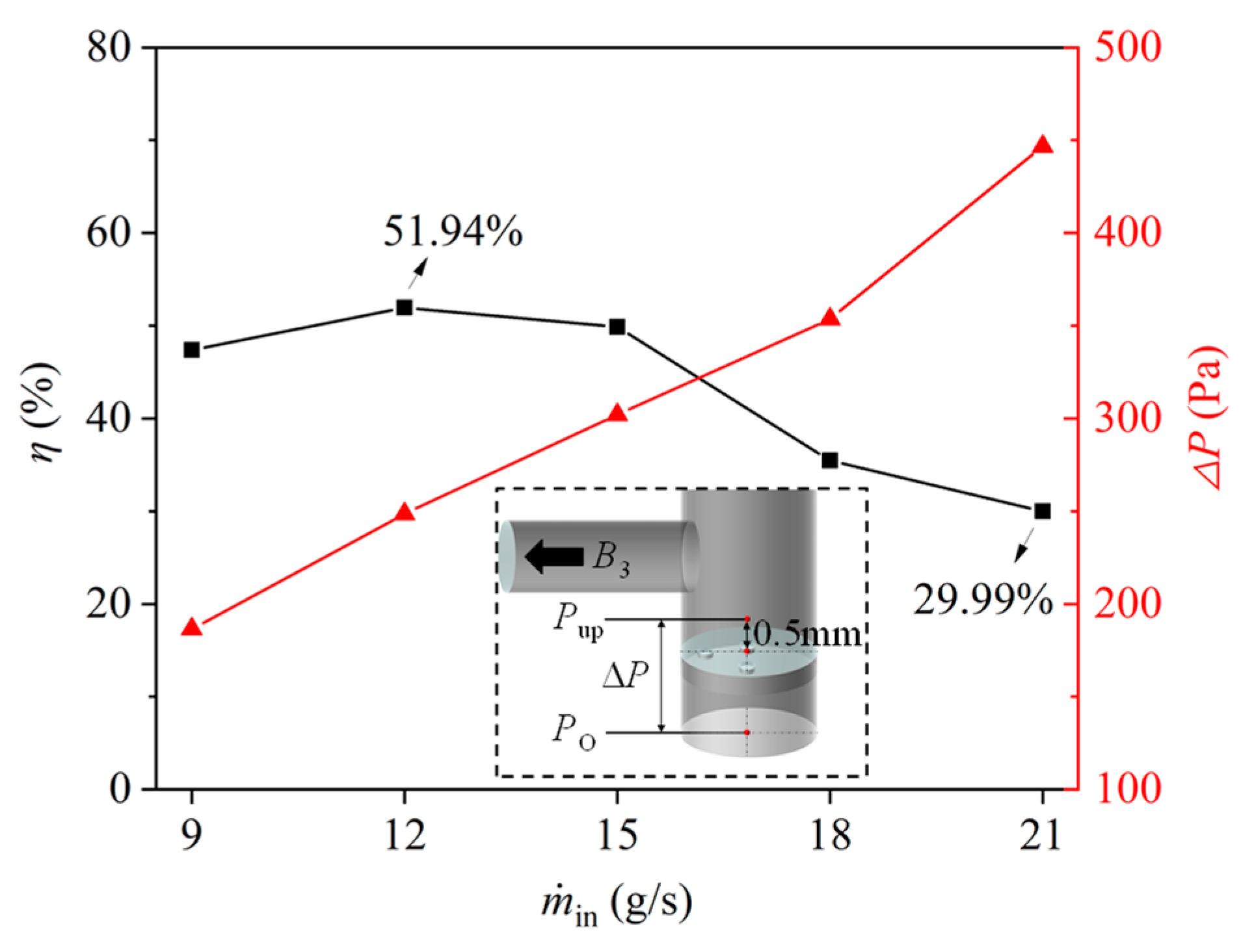
The variation of
η under different
ṁin is depicted in
Figure 4. It can be observed that with the increasing of
ṁin,
η increases firstly to the maximum value of 51.94% at
ṁin = 12 g/s and then decreases. When
ṁin is larger than 15 g/s, the degradation of
η becomes severer. It becomes 29.99% at
ṁin = 21 g/s. This will be discussed in the following section. The pressure difference (Δ
P) crossing the orifice-baffle, which is one of the main driving forces for the liquid drainage [
16], increases with the increasing of
ṁin. This is because more liquid flows towards the right side of the orifice-baffle, leading to an increase in the height of the liquid film above the orifice-baffle. Thereafter, the static pressure above the orifice-baffle increases.
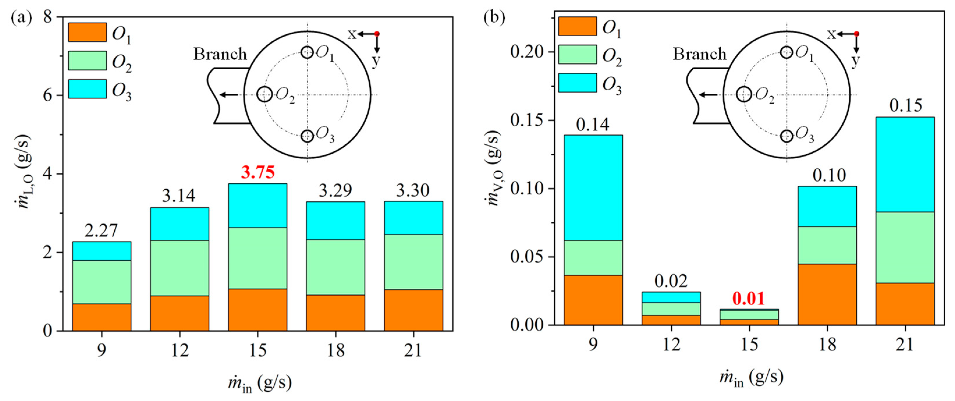
To obtain a deep understanding of the flow characteristic and discover the causes of deteriorated vapor-liquid separation performance, the mass flow rates of the liquid drainage and vapor leakage through the orifices, i.e.,
ṁL,O and
ṁV,O, are analyzed, as shown in
Figure 5. As mentioned above, there exists a strong liquid impact at the right side of the baffle,
O2, being the furthest away from the liquid impact, has a higher
ṁL,O than
O1 and
O3. Different from
η that is peaked at
ṁin = 12 g/s, the peak of
ṁL,O = 3.75 g/s appears at
ṁin = 15 g/s. This is explained as: compared to
ṁin = 12 g/s,
ṁin = 15 g/s has a higher
ṁL,O because of a larger driving force, but its
FL is much smaller owing to the more liquid within
ṁin, leading to a lower
η given that
FV in these two cases are negligible (see
Figure 5b).
ṁL,O maintains at around 3.30 g/s when
ṁin is 18 g/s and 21 g/s. Meanwhile,
ṁV,O weakens the vapor-liquid separation performance, derived from Equations (11) and (12). As seen in
Figure 5b,
ṁV,O has an opposite trend to
ṁL,O. It decreases at first when
ṁin is smaller than 15 g/s and then increases to 0.15 g/s at
ṁin = 21 g/s. The vapor only leakage about 0.02 g/s and 0.01 g/s as
ṁin equals to 12 g/s and 15 g/s, respectively. This is due to the liquid film above the orifice-baffle in these two cases being able to resist the impact of the liquid flow from the wall, in which the orifices are rarely affected by the fluid impact and only a small amount of vapor leakage. Conversely, much vapor leakage out from the orifice under the other three
ṁin because of the unstable liquid film above the orifice-baffle. Moreover, the vapor is escaped out from
O2 is less than that from
O1 and
O3 owing to its farthest distance away from the liquid impact.
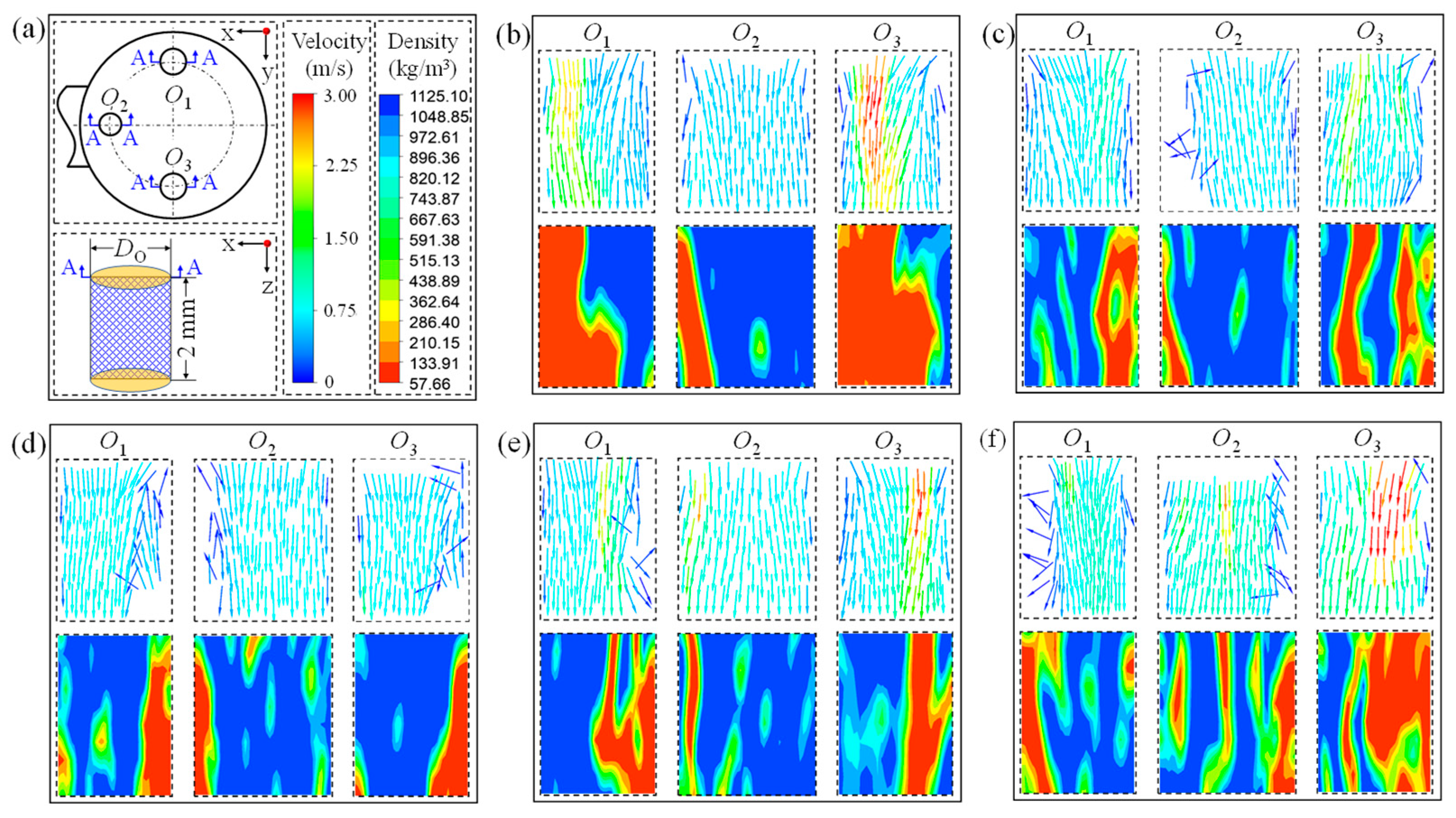
Figure 6 displays the distributions of vector and density at the central section of the orifices. Clearly, the flow characteristics in
O2 are significantly different from those in
O1 and
O3. When
ṁin is between 9–15 g/s, the vapor velocity in
O2 is normally lower than 1.5 m/s and it mostly exists near the wall of the orifice. As
ṁin increases, the vapor with high velocity begins to appear in
O2, which indicates more vapor leakage. This phenomenon is mainly due to the induced stronger liquid impact on the orifice-baffle at higher
ṁin. As a result, the liquid film above the orifice-baffle is unable to resist the liquid impact and meanwhile the interactions between the liquid and vapor becomes intensive, leading to the increasing of
ṁV,O. As for
O1 and
O3 that are closer to the liquid impact region, they are more likely to have a higher vapor velocity. As shown in
Figure 6b, the velocity of the vapor in
O1 and
O3 can be up to 3 m/s as
ṁin = 9 g/s. However, with more liquid accumulated on the orifice-baffle (
Figure 6c,d), the effect of the fluid impact on these two orifices weakens, with only a little vapor leakage out from the orifices. Further increasing
ṁin (
Figure 6e,f), the liquid impact is enhanced again, contributing to a higher vapor velocity in
O1 and
O3. Summarily, the effects of the liquid impact on the orifice are the competitions between the liquid film on the orifice-baffle and
ṁin. At the lower
ṁin, the liquid film is too thin to resist the liquid impact and, consequently, the vapor escapes from the orifices, whereas at the higher
ṁin, the interactions of the liquid and vapor are upgraded and the vapor is carried to the orifices by the liquid.
3.2. Flow Characteristics in the Branch Outlet
As shown in
Figure 7, the maldistributions of
ṁB and
xB in the branch outlets are rather significant. The liquid mass flow rate in each branch outlet (
ṁL,B) increases with the increasing of
ṁin. Moreover, the liquid flows into the header and jets on the header wall of the header. A part of the liquid breaks up into droplets that are thereafter dragged into the branch outlets by the vapor, which is termed as “droplet entrainment”. A similar phenomenon was also found by Li [
12] and Zheng [
20]. Obviously,
ṁL,B in
B3 is remarkably higher than that in
B1 and
B2. This is because the liquid flows to
B3 is not only by droplet entrainment, but also comes from the overflowing liquid from the orifice-baffle that cannot be drained promptly. However, the vapor in the branch outlet is more uniform than liquid owing to its lower inertia force.
ṁV,B in
B1 is slightly lower than
B2 and
B3 for the considered
ṁin.
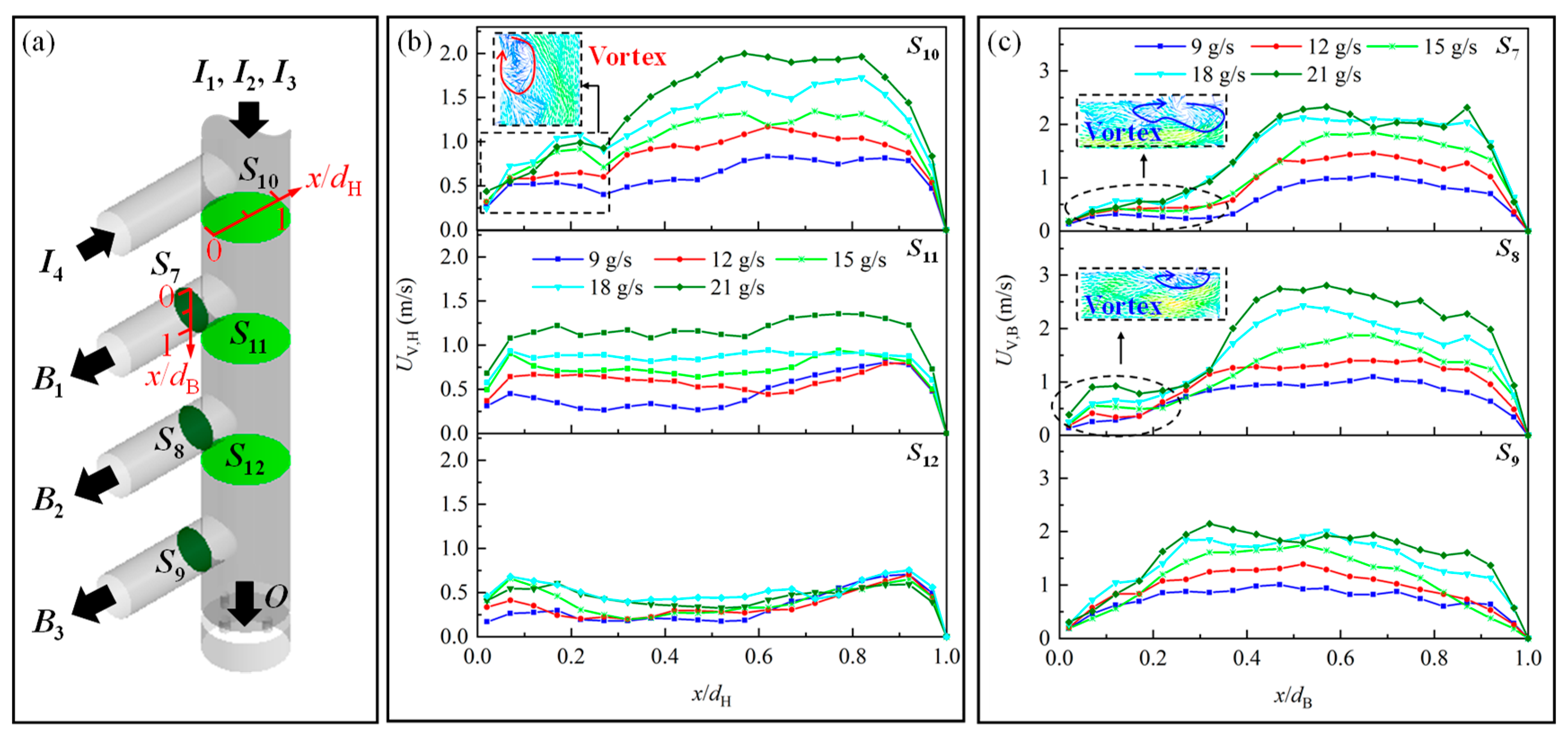
The droplets which enter the branch outlet is mostly due to the drag of the vapor. Hence, the vapor velocity is essential. To further explore the vapor flow characteristic, the vapor velocity distribution along each branch outlet and the specific header planes are plotted in
Figure 8. The two-phase fluid flows from the branch inlet
I4 and mixes in
S10. Due to the inertia, the fluid gathers on the right side of the header and a vortex is generated on the left side, resulting in the vapor velocity on the left side being lower than that on the right side. After
S10, the fluid continues to flow downwardly, and then a part of it is divided into the
B1 because of the suction of the branch outlet. The fluid is more accumulated at the lower part of
B1 due to the inertia (
S7), in which the vortex exists above the
B1 and shows a vapor velocity non-uniform distribution. The other part of the fluid from
I4 that cannot enter
B1 in time will keep flowing in the header. In this way, the fluid also flows on the left side, resulting in a lower non-uniformity at
S11. Similarly, the vapor velocity distribution in the next branch outlet (
S8) and header (
S12) are close to the
S7 and
S11 respectively. However, due to the diversion of the fluid, the vapor velocity decreases correspondingly. On the other hand, in the
B3, the distribution of the vapor velocity is more uniform. This is mainly due to the fact that
B3 has a maximum mass flow rate than
B1 and
B2, in which case the fluid can be fully fill at the
B3, where there is no vortex generated. With the increase in
ṁin, not only does the velocity increase but it also improves the non-uniformity of the velocity distributions.
3.3. Mechanism Model of Droplet
As described above, the droplets in the branch outlets are dragged by the vapor. Meanwhile there exist vortexes in the header and the branch outlets, resulting in the mainstream area being smaller than the actual cross-section area, which substantially increases the local mass flux. According to the droplet model proposed by Tan [
21] that is listed in
Appendix A, the droplet diameter (
d) is mainly affected by the mass flux that is relevant to the vortexes. Hence, the vortex has a great influence on the droplet entrainments. However, the vortexes are sometimes neglected when analyzing droplet [
13]. In order to reveal the effect of the vortex on droplet characteristics, the force on the droplets is analyzed. Moveover, a critical vapor velocity for “droplet entrainment” (
UV,C) is also proposed. The following assumptions are made for the droplets: (1) they are spherical; (2) they have the same diameter in the same branch outlet.
Taking
B1 as an example,
Figure 9 demonstrates
d in the header and the vapor velocity in
B1 with and without vortex. It is observed that an increase in
ṁin leads to an enlarged droplet diameter and decreased vapor velocity simultaneously. In addition, the existence of the vortex decreases the droplet diameter by up to 1.76 times and increases the vapor velocity in the branch outlet by 35.10%, which significantly affects the forces of the droplet.
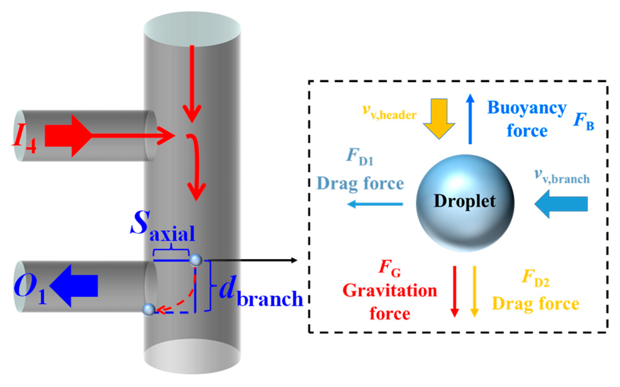
The force balance of the droplet is further established and analyzed. The droplet in the header is generally subjected to four forces (
Figure 10), they are the gravitation force (
FG), the drag force (
FD2) and the buoyancy force (
FB) in the vertical direction as well as the drag force (
FD1) in the axial direction. The details of these four forces are described in
Appendix B. In these four forces,
FG and
FB are only dominated by
d. Moreover
d, the drag force (
FD1 and
FD2) is also depended on the velocity. The higher mass flux represents the smaller droplet diameter. The drag force under different
ṁin is a result of the vapor velocity competing with
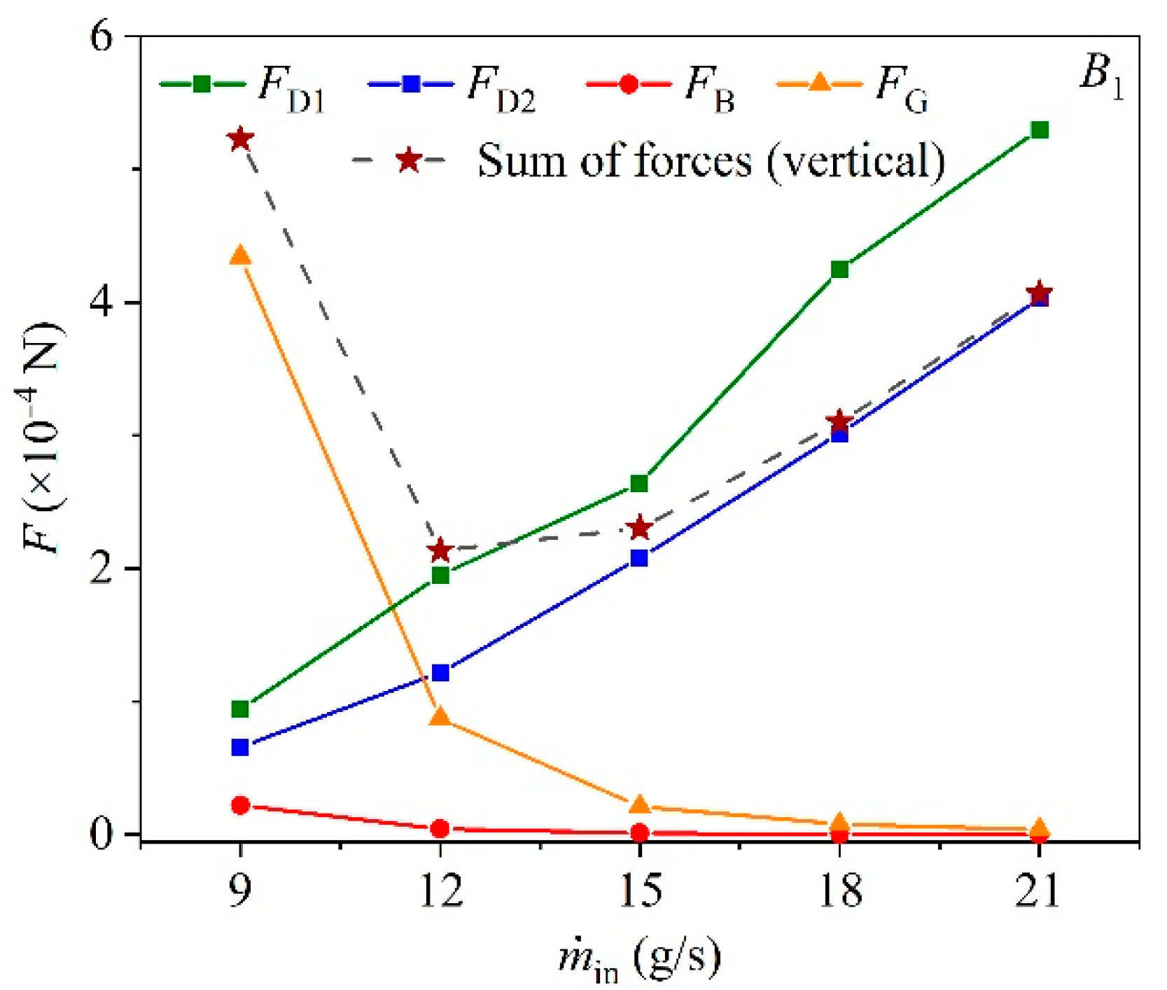
d. As shown in
Figure 11, the sum of forces in the vertical direction shows fluctuation with the increasing of
ṁin and the minimum value is 2.04 × 10
−4 N at
ṁin = 12 g/s, while the force in the axial increases monotonously.
FD1 and
FD2 increases with the increasing of
ṁin, which indicates the increasing rate of the velocity is larger than the decreasing rate of
d. Meanwhile,
FG and
FB both decrease due to the droplet being smaller when increasing of
ṁin.
FG at
ṁin = 21 g/s is only 1.02% to that at
ṁin = 12 g/s. Since
FG and
FB are only related to the density difference,
FG is constantly 20.14 times higher than
FB, which represents that in general, the force in the vertical upward is relatively small compared to the downward. Interestingly, the dominant force in the vertical direction switches from
FG to
FD2 when
ṁin is higher than 12 g/s.
When the droplets flow into the intersection of the header and the branch outlet, the axial distance for droplets to be entrained to the branch outlet is
Saxial and the vertical distance is the diameter of the branch outlet (
dB), as shown in
Figure 10. If the flowing time of droplet in the vertical direction
tvertical is longer than that in the axial direction
taxial, the droplet will be entrained to the branch outlet. Therefore, the critical point for the droplet entrainment is defined at
tvertical =
taxial. In this way, the critical vapor velocity (
UV,C) required to entrain the droplet can be obtained when the droplet in the branch outlets is located in
Saxial, as calculated as in Equations (13)–(15).
It can be observed that
UV,C is highly correlated to the velocity of both phases in the header, the vapor velocity in the branch and
d UV,C at the different axial locations under various
ṁin is plotted in
Figure 12. Clearly, the larger
Saxial requires a higher
UV,C to entrain the droplet and the growth rate of the
UV,C decreases as the
Saxial increases. Moreover, under the same axial location, for the droplet to be dragged to the branch outlet needs a higher
UV,C when
ṁin is increased. This is mainly due to the smaller
d at higher
ṁin, causing the larger acceleration and the shorter flow time
tvertical in the vertical direction.
It is worth mentioning that in this study, the velocity in the header and the branch outlets are simplified to be averaged from each plane. The distributions of the droplet are assumed to be uniform in the header. Nevertheless, for the actual flow, the distributions of velocity and the volume fraction are non-uniform and extremely complex. In future work, the distribution characteristics of these parameters are of great interest to be quantified by a refined the model to improve the model accuracy.


