
Ship’s Digital Twin—A Review of Modelling Challenges and Applications


Faculty of Maritime Studies, University of Split, Ruđera Boškovića 37, 21000 Split, Croatia
*
Author to whom correspondence should be addressed.
Appl. Sci. 2022, 12(12), 6039; https://doi.org/10.3390/app12126039
Submission received: 26 May 2022
/
Revised: 10 June 2022
/
Accepted: 13 June 2022
/
Published: 14 June 2022
(This article belongs to the Topic Virtual Reality, Digital Twins, the Metaverse)
Abstract
:The Ship’s Digital Twin (SDT) is a digital record of a ship’s behaviour or a software clone, which can be used to simulate scenarios that are expensive or hardly feasible to perform on a real object and especially in real time. The purpose of the SDT is to achieve cost reduction, obtain timely warnings of irregularities, and optimise individual ship system performances or the operation of the whole ship and to assist ship management. The aim of this paper is to describe the concept of the SDT and clarify some perplexities that may occur from initial introduction to concept. To that end, the paper identifies the steps in the SDT formulation process and methods used in each step of the process. Furthermore, a four-step iterative procedure for the SDT development is proposed. The applications of the concept are numerous, and some of them are presented in a review analysis in this paper. The presented analysis leads to a conclusion that should give some direction to future research in this area.
1. Introduction
Although the concept of a digital twin (DT) can be found described in the literature, e.g., as in [1], and although a digital twin as a term is being used increasingly in different fields of technical sciences, the concept remains unclear mostly in the way of differentiating a DT concept from an ordinary computer simulation model. Furthermore, the concept is sometimes related to a cyber-physical system (CPS) as described in [2,3,4,5], a part of the CPS as described in [6], or as a digital model and digital shadow, which can be combined to form a DT as described in [7].
What makes a digital twin of a ship (SDT) and how to create one in a systematic and reliable fashion were motives for this research. Therefore, this paper presents a review analysis of the SDTs developed so far, based on the available literature. It presents the concept, identifies the steps and methods used in the SDT formulation process, as well as communication protocols used in different stages of the process. The applications of the SDT are numerous, and some of them are presented in this paper.
Furthermore, the paper proposes a four-step iterative procedure for the SDT development that is based on data acquisition, data processing, modelling, and model validation. Recalibration of the model using the new data is possible, thus making the process iterative, and it is performed once the new input data become available. In the same way, SDT outputs are used on a real object depending on the level of connectivity between the SDT and the ship. Thus, the connectivity and communication level between the ship and its DT is essential.
The SDT concept relies on data it would expect for the advanced data modelling methods, such as artificial intelligence, used in [8,9,10,11,12], and data-driven modelling (DDM), used in [12,13,14], to take prime in this area. However, conventional mathematical models have often been used for the purposes of creating an SDT, as in [15,16,17,18,19,20,21,22].
SDT applications found in papers [8,9,10,11,12,13,14,15,16,17,18,19,20,21,22,23,24,25,26,27] were analysed according to the standards of the DT formulation process set in this paper. For every case study, methods used to form a DT, applications, and steps of the DT formulation process were analysed. Some of the common applications are maintenance and condition monitoring, as in [8], system identification for fault detection, as in [9], cost reduction, as in [17], remote control and monitoring, as in [24], and various applications, as in [21], whereas ships’ systems can be modelled for the purpose of decision-making support, as described in [23].
The simulation aspect of a DT concept was reviewed in [28], while ref. [29] discussed challenges in DT application for maintenance of marine equipment. Furthermore, ref. [30] analysed advantages and contrasted them with challenges, thus identifying benefits of DT implementation, while ref. [31] addressed the main research focus and future fields of interests regarding the DT concept. The literature review for DT concept applications for the purpose of maintenance was discussed in [32], while ref. [33] conducted a systematic literature review and analysed DT trends and strategies.
Main areas that need to be researched in order to efficiently implement a DT both in the maritime industry and in general were identified in [34] and include: sensor technology, signal processing and filters, modelling methods such as machine learning (ML), DT architectures, and application programming interfaces (API).
The review analysis presented in this paper gives some direction to the formulation process of an SDT and suggests further research that should be performed in that area.
2. SDT Concept Development and Methods Used
DT has many definitions, all revolving around the same idea of modelling, data acquisition, data processing, and simulation, as described in [35]. An integrated multiphysics, multiscale, probabilistic simulation of an as-built system that uses the best available models, sensor information, and input data to mirror and predict activities or performances over the life of its corresponding physical twin, as stated in [36], can be offered as the most appropriate one.
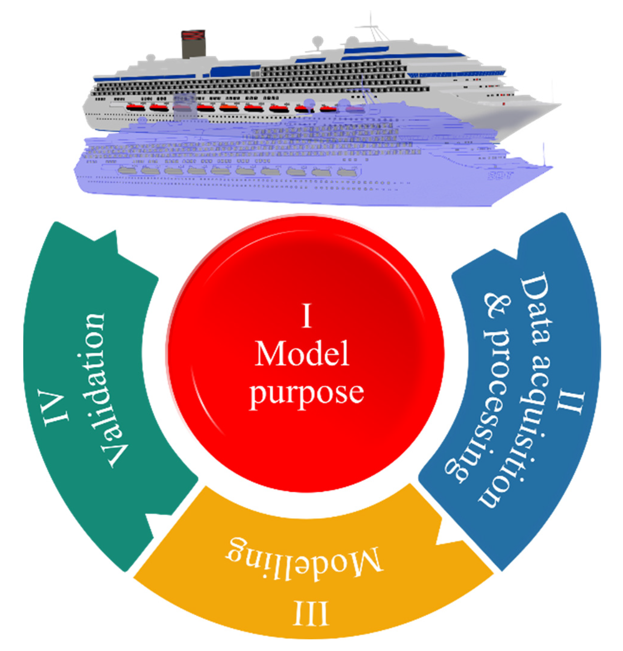
Considering the definition and taking into account related work, the procedure of creating an SDT could be divided into four basic steps that include: defining the purpose of an SDT, collecting and processing the necessary data, and modelling and validating the model. Once the purpose of an SDT has been defined, the next three steps can repeat in a cycle depending on the data availability and connectivity level between the ship and its twin, as presented in Figure 1.
2.1. The Purpose of the Model
As described in [1], an SDT concept can be divided into fields of application, and collected data for each application field are processed for later modelling, simulation, and behavioural analysis for the purpose of control, prediction, and decision-making support. Therefore, defining the purpose of the model might be considered as the initial step of the SDT formulation process.
2.2. Data Acquisition and Processing
SDT uses sensors installed onboard to collect data, such as heading, vessel speed, GPS coordinates, azimuth angles, propulsion power, engine speed of rotation, engine load, vibrations, and structural strains, depending on the purpose. However, sensor logs, or raw data, could not usually be immediately useful for a DT, i.e., it might be necessary to perform data processing to extract physical meaning from it, as noted in [1].
Therefore, data acquisition and data processing could be identified as the second step of the process. The data acquisition method and the purpose of the model are ones that would determine the choice of data processing method. For instance, stress data collected from optical sensors and stress data collected from strain gauges require different methods to extract useful information from the data.
For data processing purposes, various methods have been used, such as filtering outliers, as in [8,13], filtering noisy data, as in [18], interpolation and calculation of wave spectra, as in [16], data fusion, as in [10,12], calculating root-mean-square (RMS) values from raw data, as in [13,20], convex optimisation, as in [21], skewness and kurtosis analysis, as in [13], and Fourier transformation, as in [26].
2.3. Modelling and Modelling Methods
Processed data are then used for modelling, which can be identified as the third step. Traditional physical-based mathematical modelling has often been used; however, it would be expected for a DT concept to benefit from the application of data-based modelling tools such as time series models, artificial neural network algorithms, fuzzy logic, and genetic algorithms.
Modelling methods used for DT development in the reviewed literature vary based on scope of application, starting from conventional mathematical modelling and statistical analysis used in [13,15,17,18,21,22], the finite elements method (FEM) used in [11,12,16,20,21,26], data-driven modelling (DDM) used in [8,12,13,14], artificial neural networks (ANN) used in [8,9,10,11], grey-box modelling (GBM) in [10,27], cycle mean value (CMV) in [15,19], boundary element method (BEM) used in [24], model based systems engineering (MBSE) used in [23], and model-based design (MBD) as used in [25].
BBM represents the input–output relation based on acquired data, thus being based entirely on empirical data, while WBM represents purely theoretical modelling based on system equations, as stated in [27]. In between the two, GBM combines acquired data with the theoretical model, and its use has been proposed in [10] to develop a DT predicting fuel consumption and ship speed. Moreover, a GBM method has been proposed in [27] to develop a DT model of a boost converter as part of a shipboard power system. In [27] also, an artificial neural network (ANN) and the available data were used to develop GBM, which was validated to successfully predict fuel consumption and ship speed.
The use of an ANN and regression analysis was proposed in [8] to estimate the effect of fouling on ship speed and hence on fuel consumption, operating costs, and emissions, requiring only operational data as input. In addition, changes in the speed loss distribution were calculated with robust regression. The combined use of the ANN and statistical analysis was proposed in [9] by implementing two algorithms on data collected through a step-input test on the electric propulsion motors in a four-corner manoeuvre scenario. The first algorithm calculates the mean value and standard deviation of an electrical current and propeller speed, measured at different set-points of a propulsion motor power. The acceptable range of electrical current for each set-point was set to three standard deviations below and above mean value, indicating a normally operating motor. The case of values going out of range for more than two seconds was considered as a fault of the propulsion motor. The second algorithm is the ANN algorithm, where the input nodes are set-points of propulsion motor power, motor speed, and current, and the output node represents the state of the propulsion motor, where 0 represents a normally functioning motor, while 1 represents a faulty motor. If the output node value is at 0.8 for more than 0.5 s, an alarm is triggered.
CMV is a mathematical modelling method for the transient response of machinery working in iterative cycles such as a marine diesel engine, and its use was proposed in [15], thus developing a cycle mean value (CMV) model of a marine diesel engine that was further compared with a model developed using the Runge–Kutta method. A statistical analysis method was proposed in [21], where data acquired from DT and the real system (physical twin) were analysed, thus forming a basis for data correction and error detection such as detecting outliers or stuck values caused by malfunctioned sensors.
DDM represents modelling based on the acquired data, and it was proposed in [14] to develop a DT of a ship and ship crane system. MBSE represents the formalised application of models throughout the lifecycle of a physical twin, as described in [37,38], and it was proposed in [23] to develop a DT of a cruise ship. Furthermore, MBD represents a modelling method entirely based on simulation models, and its use was proposed in [25] to form a DT of a ship electric power system.
FEM and the 3D panel method were used in [16] to perform an analysis with reference to the Classification Society ClassNK guidelines for direct load analysis and strength assessment. A DT of a cruise ship structure was created from a 3D model. Combined weather data and data from the AIS (Automatic Identification System) were used as the basis for the analysis using Rayleigh distributions in 3D NAPA software. Ship speed and wave direction were used as input variables for the 3D panel method, where wave scatter plots were created from the time series of wave conditions at specific positions of a ship.
In [20], the use of FEM was proposed to analyse the ship drivetrain based on data acquired by implementing sensors on a laboratory drivetrain test rig model. Similarly, ref. [11] proposed an FEM and ANN approach to form two models of a ship structure, while ref. [26] proposed an FEM approach to build the DT of a ship-synchronous generator and conducted transient analysis using wavelet transformations and Fourier analysis.
Mathematical modelling of the ship behaviour for the DT development was been proposed in [22], as well as in [18], where the power system of a ship was modelled using mathematical equations along with blackout dynamics and generator load distribution. Few blackout prevention methods have been proposed based on power consumption monitoring, such as fast load reduction. A DT model of a ship’s hull, by fusing several models based on FEM, CAD, and machine learning, was proposed in [12].
Ship Power and Propulsion Systems were modelled in [17], in which the diesel engine was modelled by a transfer function with the fuel index as the input variable and the generated torque as the output variable. An alternator was modelled in the dq-reference frame, as a three-phase synchronous machine with salient poles, where the swing equation was used to describe the rotor dynamics. The fuel supply system was modelled as a PI controller that controls the fuel index as a function of the difference between measured and reference speed, i.e., speed error. An automatic voltage regulator (AVR) controlling the excitation voltage was modelled as a regulator with an error as an input, calculated as a difference between measured and reference voltage. Switchboards were modelled as a set of breakers described by resistance. Three-phase induction propulsion motors, powered by AC/AC inverters, were modelled in the dq-reference frame, where direct torque control with space vector modulation was used as the control strategy. Fixed-pitch propeller dynamics were modelled with varying torque as a function of propulsion power and shaft speed, while auxiliary and hotel loads were modelled as three-phase loads with adjustable reactive and active power for different types of load simulation. Batteries were modelled as lithium-ion type with voltage as a function of current and state of charge. The systems were modelled in Matlab/Simulink and wrapped as Functional Mock-up Units (FMUs) as four sub-simulators using the Open Simulator Platform (OSP) architecture based on the FMI (Functional Mock-up Interface) standard as described in [39]. Modelling of a three-phase electrical motor in a dq-reference frame can be found explained in [40].
The BEM was proposed and used in [24] to develop a DT of a scaled ship model used for remote control. The scaled model of a ship was tracked using a stereoscopic system with five reflective targets, while the DP (Dynamic Positioning) system transmitted the rotational speed of the propellers and the azimuth angle to the operator’s screen.
2.4. Validation of the Model
Once the model is formed, it should be tested in order to determine its accuracy and reliability. The validation of the model is then the fourth step of the process, and different measures of evaluation have been used for that purpose.
Validation measures, i.e., numerical evaluation measures, include the acceptable range of values in a specific operating condition based on standard deviation (SD) σ, as used in [9,10,18], relative error (RE), as used in [15,18,27], root-mean-square error (RMSE), as in [41], persistency index, as used in [41], mean absolute error (MAE), as used in [41], mean error (ME), as used in [10], and the squared sum of residuals and correlation coefficient R, as used in [11].
Graphical evaluations of model responses have also been used, such as scatter plots, as used in [9], and histograms and linear robust regression, as used in [8], and direct comparisons of the model response to measured data have often been used, e.g., as in [15,17,18,20,21], and the validation method of the model was sometimes not specified, as in [14].
Once it becomes available, the new data can also be used for recalibrating the model, which makes the whole process iterative. Once it is recalibrated, the model must go again through the validation process before it can be used.
3. Connectivity Issues and Communication between the Ship and SDT
An SDT can be defined as a synthesis of a sensor network installed on a ship, providing insight into a real ship by observing various systems onboard, and simulation software where operational insight into users is given as a result of processing acquired data whether onboard or onshore, in a cloud, operating centre, etc. This means that the communication between an SDT and a real object, the ship, is very much alive and represents another issue in the process that needs to be considered in terms of concept development, which is also identified in [12] as a challenge that limits SDT’s potential.
Regarding the level of connectivity between the DT and a real object, six DT topologies were proposed in [42], namely: disconnected DT, connected DT, embedded DT, aggregated DT, multi-device DT, and combined DT. A disconnected DT has no connections with a real physical twin, due to connection nonfeasibility, unlike a connected DT, which has a stable connection to the physical twin all the time. An embedded DT is embedded in a physical twin, while an aggregated DT is composed of multiple DTs. A multi-device DT is connected to multiple physical twins, while a combined DT combines several aforementioned topologies. As communication between the ship and its twin should be in real time, in the best case, it can be assumed that DT concepts should stream towards a connected DT topology. However, this issue is expected to be a subject to compromise between different influencing factors, including the economical side as well.
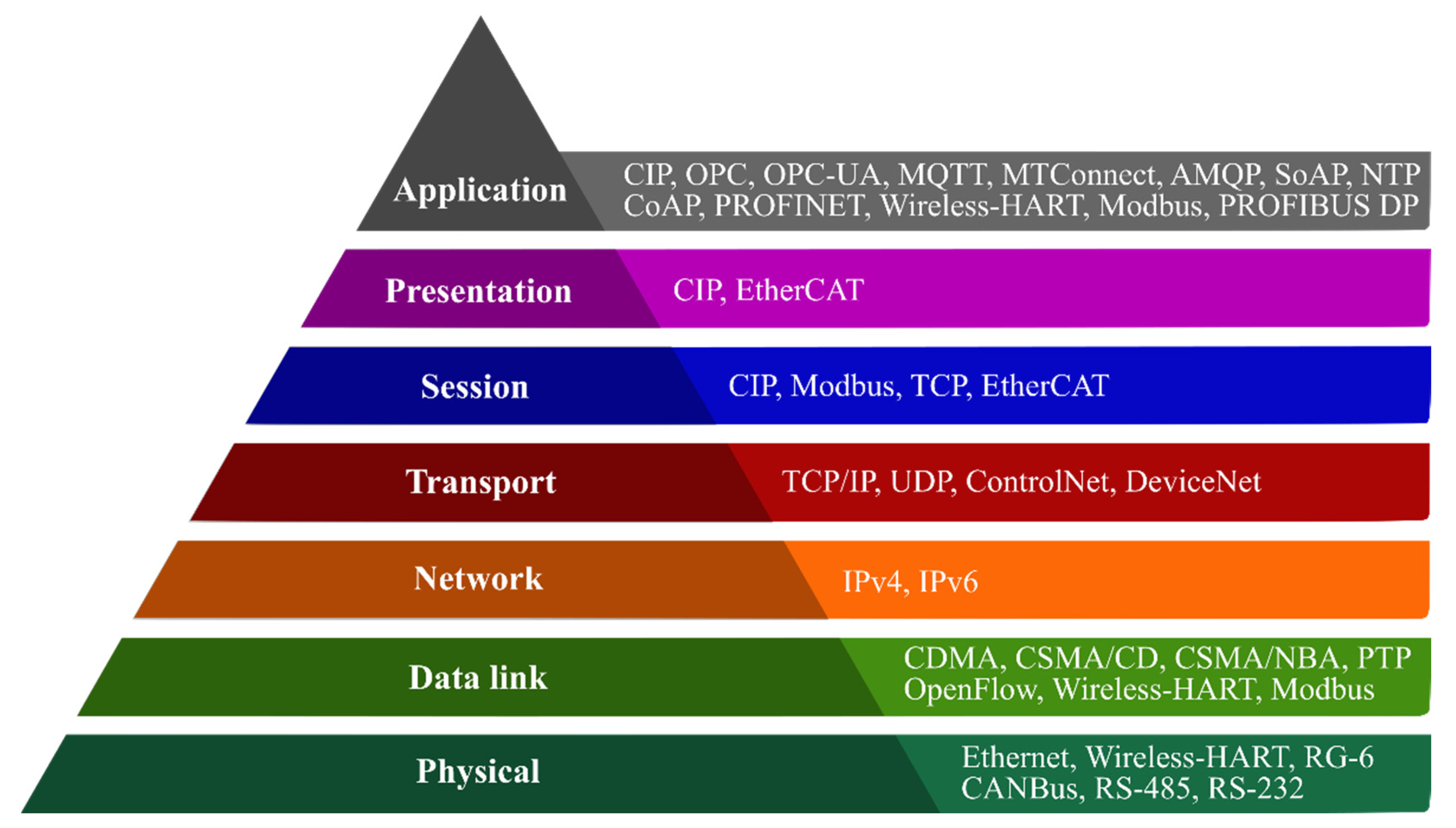
Commonly used communication protocols and standards in DT formulation, in accordance with the Open Systems Interconnection (OSI) reference model, are reviewed in [43,44]. The OSI reference model is a conceptual model, enabling network communication between diverse communication systems or devices. It is based on seven stacked-up layers, each responsible for a specific purpose in the communication process and responding to the requests of an adjacent layer. Seven layers are, starting from the first: physical, data link, network, transport, session, presentation, and application layer, as presented in Figure 2.
The physical layer defines properties of a physical medium, i.e., communication channel for data exchange. The data link layer defines the format of the data exchanged over the network. The network layer breaks up data into smaller units, i.e., data packets, reassembles them on the receiving device, and routes data to reach their destination. The transport layer is responsible for error control to ensure that the data are completely received or transmitted. The session layer is responsible for opening and closing a communication session for data transmission to prevent waste of processing resources. The presentation layer ensures a correct and usable data format. The last layer, application layer, being the only layer that is in direct interaction with the user, is responsible for presenting data in a user-perceivable format.
Commonly used physical layer standards are Ethernet, Wireless-HART as explained in [45], RG-6, CANBus, RS-485, and RS-232. The data link layer utilises standards such as CDMA (code-division multiple access), CSMA/CD (carrier-sense multiple access with collision detection), CSMA/NBA (carrier-sense multiple access with nondestructive bitwise arbitration), Modbus, OpenFlow, PTP (precision time protocol), and wireless-HART as explained in [45]. The network layer includes IPv4 and IPv6 protocols as explained in [46]. The transport layer protocols include the TCP/IP (transmission control protocol/Internet protocol), UDP (user datagram protocol), ControlNet, and DeviceNet, while the session layer includes the CIP protocol family, Modbus, TCP as used in [5], and EtherCAT. The presentation layer includes the CIP (Common industrial protocol) family and EtherCAT. Finally, the application layer includes the CIP protocol family, OPC (Open platform communications), OPC-UA (Open platform communications—Unified architecture) as used in [47] and explained in [45], MQTT (MQ Telemetry transport) as used in [14] and explained in [45], MTConnect as explained in [42,48], AMQP (Advanced message queuing protocol) as explained in [45], SoAP (Simple object access protocol), CoAP (Constrained application protocol) as explained in [45,49], NTP (Network time protocol), Wireless-HART, Modbus as used in [14], PROFIBUS DP, and PROFINET.
4. Applications
Generally, applications can vary; however, they could be classified into some basic groups such as condition-based maintenance and predictive maintenance, as in [8,23], decision-making support, as in [12,22,23], condition monitoring, as in [9,16,26], cost reduction, as in [17], testing and simulation, as in [24], testing the integration of various systems onboard, as in [1], training personnel, as in [50], and overall optimisation, as in [10,13,18].
4.1. Maintenance and Condition Monitoring
Condition-Based Maintenance (CBM) is of great importance to the maritime industry as it can prevent unexpected failures due to the wear-off and/or stress fatigue that occur over time, and which can cause significant expenses or even disasters. The DT concept for the purpose of CBM is further justified as the blackout incident of the Viking Sky cruise ship could have been avoided, as stated in [51], by simulating and detecting possible fault scenarios using the DT of a ship. The incident occurred due to the loss of lubrication oil pressure of generator diesel engines, caused by heavy sea and low lubricating oil levels in the tank. Such a failure forced engines into a shutdown procedure, which caused a blackout and, consequently, loss of propulsion and near grounding, thus forcing the crew and passengers to abandon the ship.
The effect of propeller and hull fouling on ship speed was estimated in [8]. The fouling process is relatively fast and its impact on the overall efficiency of the ship can be estimated to within a few months, which opens opportunities for maintenance optimisation as a typical sailing interval takes about four to five years. The research results presented in [8] showed positive correlations between the hull and propeller condition and the speed loss. Moreover, inadequate hull and propeller performance is estimated to reduce the efficiency of the entire world fleet by 9–12%, as stated in [8].
As the data acquired can be used to make predictions and track the actual condition, it is possible to schedule maintenance according to these calculations, i.e., DT’s predictions. Furthermore, the recorded data may be used to determine maintenance efficiency, based on the recorded condition before and after maintenance activity.
DTs can be used to simulate, analyse, and predict environmental effects such as wind, waves, and ocean currents on the ship structure. In [16], analysis was performed to estimate the fatigue damage and calculate the cumulative damage based on the collected data on a real cruise ship during 970 days of operation. The resulting fatigue damage estimates were further used to conclude the structural damage and remaining fatigue life of a cruise ship balcony.
In [20], analysis was performed for the purpose of condition monitoring and maintenance of a ship drivetrain, and vibration analysis. The results indicated a lower simulation accuracy with the increase in model fidelity, thus dictating further research as low-fidelity models were found inappropriate for digital twin applications. In [11], research was conducted for the purpose of condition motoring of ship structures, thus identifying the ship structures to be monitored and adequate strain sensor location. The paper [25] proposed a DT of a ship electric power system for the purpose of the offline simulation of maintenance and subsystem upgrades. Research has been conducted to investigate requirements for the MBD methodology, as well as the HIL (Hardware-in-the-Loop) capabilities of proposed methodology.
In [13], implementation possibilities of the DT concept were researched by conducting full-scale measurements on a ship, thus installing sensors and analysing acquired data. The results of the research imply further actions such as the implementation of real-time data acquisition, processing, and transmission infrastructure ensuring benefits for the stakeholders of a ship by means of optimising maintenance intervals, remote assistance, structural stress analysis, autonomous operation, and improving the safety of navigation.
In [26], a DT of a ship-synchronous generator was proposed for the purpose of condition monitoring and mechanical defects identification. Transient analysis was conducted, making it possible to identify abnormalities in the frequency spectrum of the forces, electrical current, and voltage, thus identifying mechanical malfunctions. The proposed approach still needs to be validated.
A system identification performed for the purpose of condition monitoring and fault prediction can be found in [9], as it showed the development of a DT fragment of an experimental autonomous ship. The DT development was based on a 1:20 scaled model of a ship being built. The identification was performed using proposed algorithms on data collected during a manoeuvre scenario that couples swaying, surging, and yawing motions.
4.2. Decision-Making Support
Knowledge and experience required for shipbuilding is spread through several engineering fields. To overcome the complexity issue, shipbuilders are turning to computer-aided technology, which can then be used to form the basis for a DT. In addition, ship owners are increasingly demanding lifecycle projections and decision-making support, where the power generation system will have the greatest benefit through process and maintenance optimisation, especially throughout a ship’s lifecycle.
In [12], a DT model of a ship’s hull was proposed for the purpose of decision-making to preserve structural integrity. Due to the recent implementation and slow dynamics of hull processes, the proposed concept has not been validated yet.
Paper [23] proposed a DT of a cruise ship, which is among the most demanding ship types for shipbuilders due to the requirements of safety, comfort, entertainment capabilities, reliability, and effectiveness. The cruise ship’s DT was proposed to provide decision-making support and alerts, as well as to predict changes in the ship over time.
Paper [22] proposed a DT application for ship trajectory prediction utilising real-time visualisation of the predicted trajectory, thus augmenting the current scene of the environment on the computer screen in the wheelhouse. The proposed approach offers real-time decision-making support for navigating in hazardous navigation areas but needs to be further researched and validated.
4.3. Cost Reduction
Paper [17] presented a DT of a ship electrical power and propulsion system, consisting of two diesel generators (DG1 and DG2), two propulsion electric motors, a fuel supply system, switchboards, and AVR units. The simulation experiments were performed to simulate events in a consecutive order, enabling conclusions about the operation of the ship’s power system. The experiment confirmed expected system dynamics by means of frequency and voltage fluctuations after increasing and decreasing load, as well as the controller dynamics when sharing loads between generators. OSP enables the connection of models of various subsystems, usually covering different engineering fields to form an overall model of a system, thus enabling the collaboration of experts from various fields of engineering on a single platform, which results in time and money savings. The advantage over other simulator solutions lies in the fact that the OSP is an online open-source standardised and collaborative environment for model exchange in maritime industry.
4.4. Remote Control and Monitoring
Paper [24] presented a DT of a scaled ship model that uses a DT to control the model remotely by adjusting the set points through a DT interface. There were four possible applications of the DT proposed in [24], ranging from monitoring functionality, identifying the ability of the DP system to maintain position, predicting ship behaviour in future operations, and simulating various parameters not considered during exploitation. The tests of the concept were performed in the Numerical Offshore Tank at the University of São Paulo, where measured variables were directly used for 3D visualisation of a DT’s movement on operator screen.
One of the few applications of the DT concept in real-time was presented in [14], proposing a simulation and remote-control centre concept utilising real-time data transfer from a ship and ship crane system to an onshore simulation and control centre for the purpose of remote control, monitoring, and crew assistance.
4.5. Various Applications
Modelling a ship’s power system to increase the overall efficiency was studied in [18], demonstrating an improvement in response time and false blackout detection. Operating costs were reduced by the proposed long- and short-term generator load distribution optimisation, which resulted in 6% to 8% fuel savings and lower maintenance costs. The propulsion system was optimised to reduce its impact on the bus-bar frequency by predicting disturbances and thus power fluctuations via the proposed quasi-static load limiting controller based on real-time measurements. Power redistribution control was proposed to mitigate voltage and frequency fluctuations that dynamically affect thrusters and other large consumers, drastically improving grid stability without affecting the response of the ship.
In [10], a novel approach was proposed to develop a DT model for voyage performance evaluation by predicting ship speed and fuel consumption of a bulk carrier where AIS data and noon reports were expanded with weather hindcast data. The developed model was validated, thus consequently enabling the basis for GHG (greenhouse gas) emissions reduction as the ship speed, fuel consumption, and GHG emissions are correlated. As the proposed modelling approach did not include sensor-collected data, it can be applicable on various ships and, in the case of a fitted sensor network on-board, could be further expanded.
When designing a DT, as in any modelling, a compromise must be made between the complexity and real-time performance. The paper [15] proposed a modelling approach of a marine diesel engine that satisfies that compromise. The proposed model outperformed the differential equation model based on the Runge–Kutta method in terms of calculation speed, while acquiring low relative error values during HIL experiments in the validation procedure on a marine diesel engine test-bed, thus making it a basis for anomaly detection, failure mode management problems, tracking thermal efficiency, and emissions prediction.
In addition to the aforementioned purposes, ref. [21] proposed a DT concept for the purpose of real-time sensor data reconstruction and error detection and correction, thus validating and correcting data acquired from the heat exchanger system. The method proposed in [21] offers a wide range of applications and is not limited to heat exchanger systems.
In [27], a DT model of a boost converter as part of a shipboard power system was proposed. The paper dealt with problems in grey-box parameter identification methods rather than focusing on the application purpose, thus comparing two algorithms for minimising the error between the predicted and measured values. As a result, further work was been proposed to investigate the best global optimisation algorithm used for parameter fitting.
5. The Review Analysis of SDTs
The analysis of the models, methods, applications, and steps of DT formulation processes developed so far and presented in the reviewed literature is listed in Table 1. The analysis was performed in accordance to the four-step iterative process for the SDT development proposed in this paper.
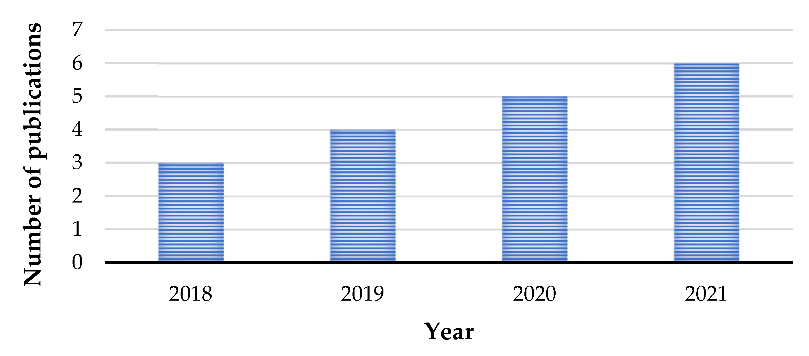
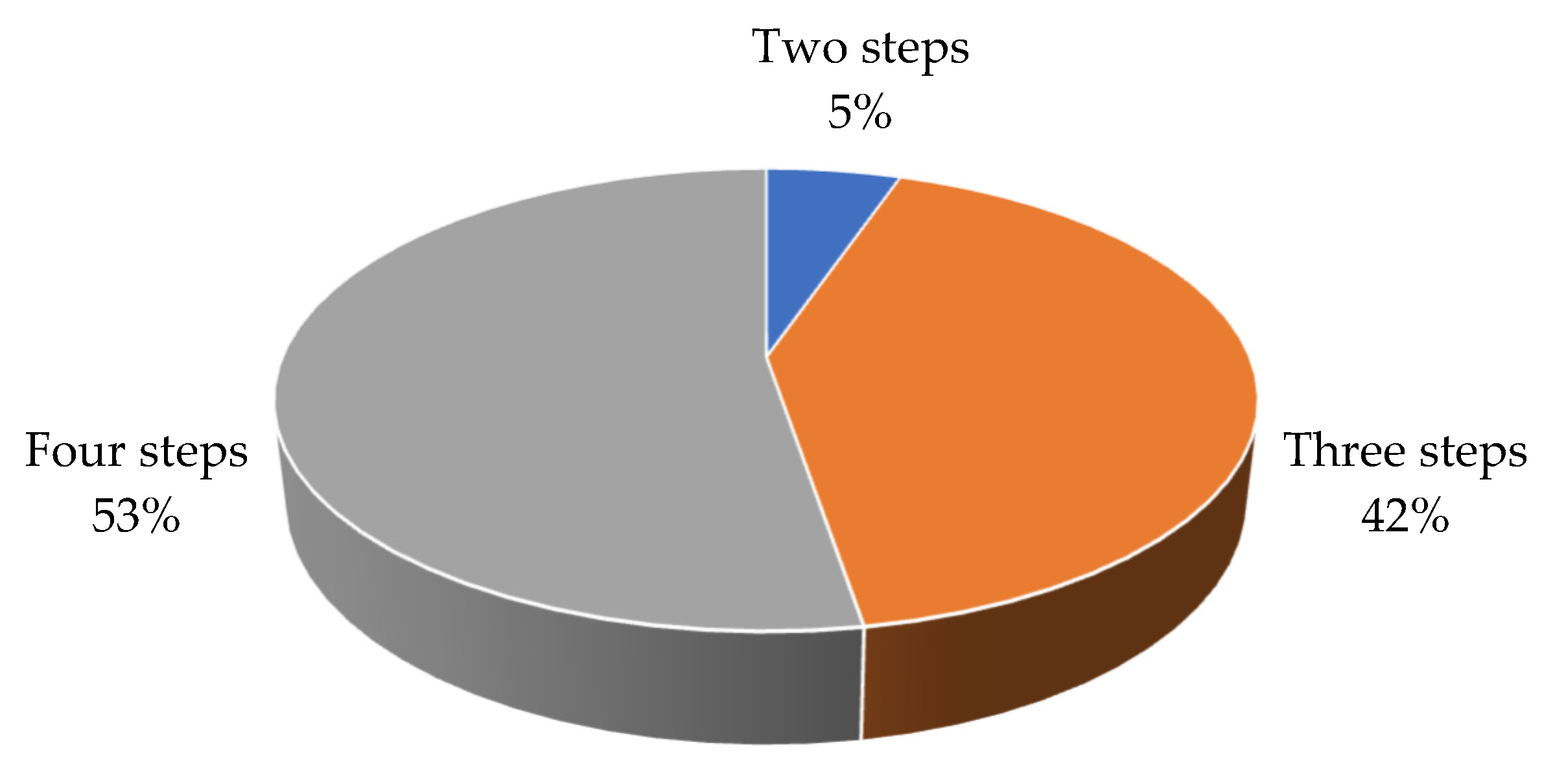
By analysing the number of SDT publications in the past four years, a positive trend in the number of publications per year can be noted, as shown in Figure 3. The results of the analysis of the SDT formulation concept in accordance to the steps proposed in this paper indicate that 53% of the reviewed publications use all proposed steps, while 42% of the reviewed publications use three, and 5% use two proposed steps, as shown in Figure 4. The most common step not being used is the fourth step, i.e., the validation, not used in 89% of the publications that did not use all steps.
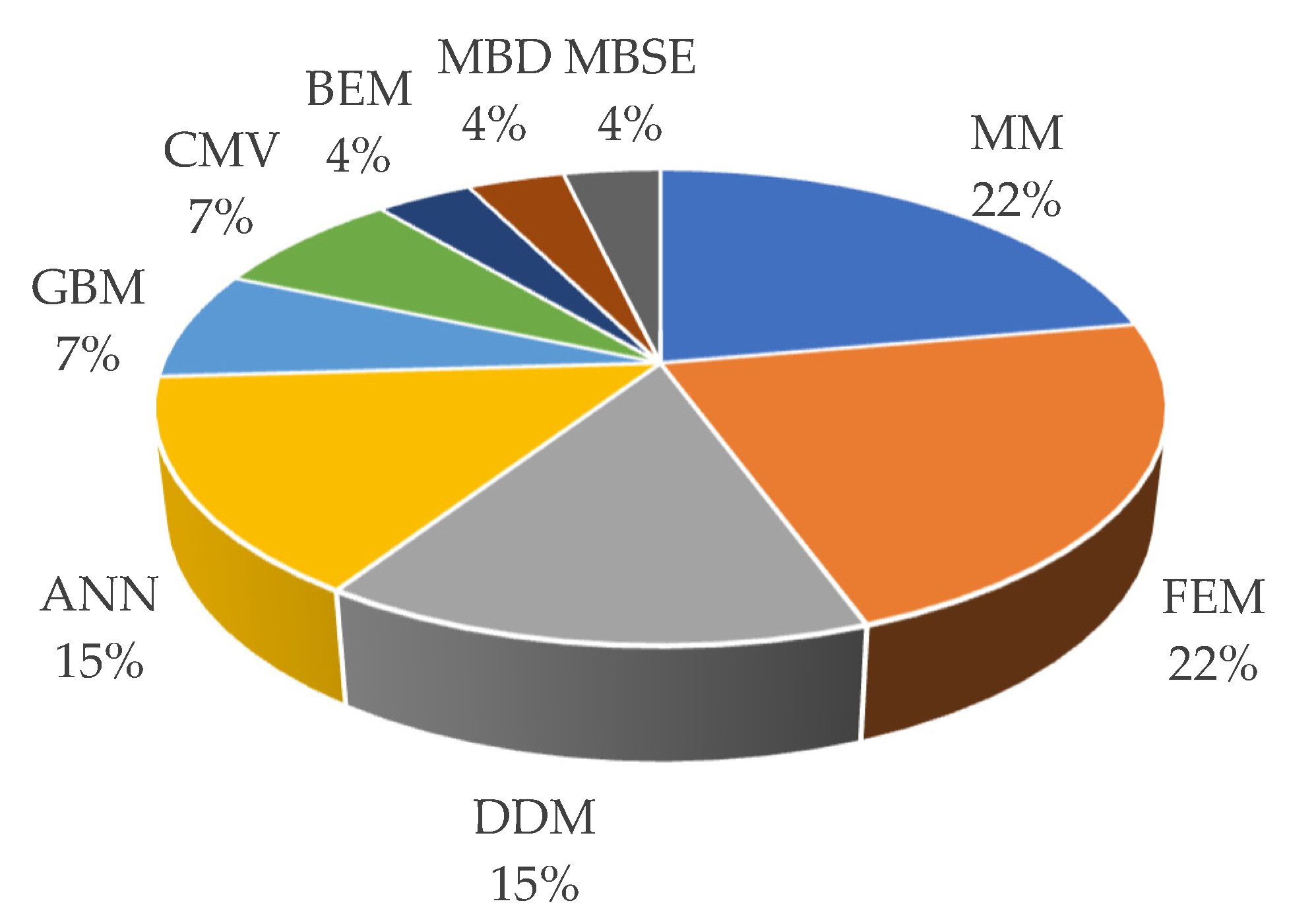
Nine different modelling methods have been used in the reviewed papers, as well as the combinations of these methods, where mathematical modelling and FEM are the two most commonly used, as shown in Figure 5. Both were used in 22% of the reviewed publications, while classical data-driven modelling methods and its modern sibling, ANNs, were each used in 15% of the cases considered. Grey box modelling, as a hybrid of the physical and data-based approach, has been used in 7% of the cases, as well as CMV, while the rest of the methods have been used in single cases.
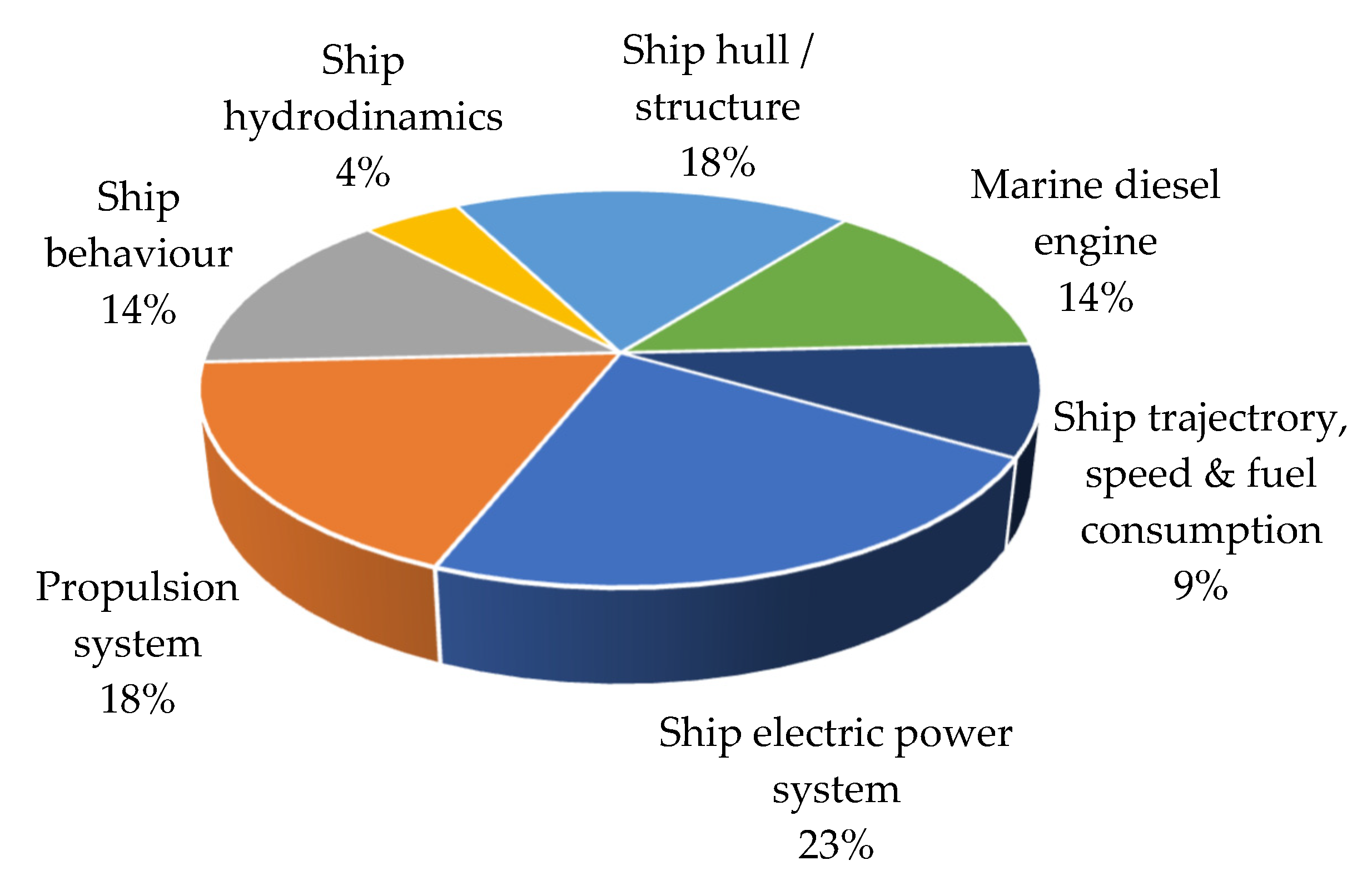
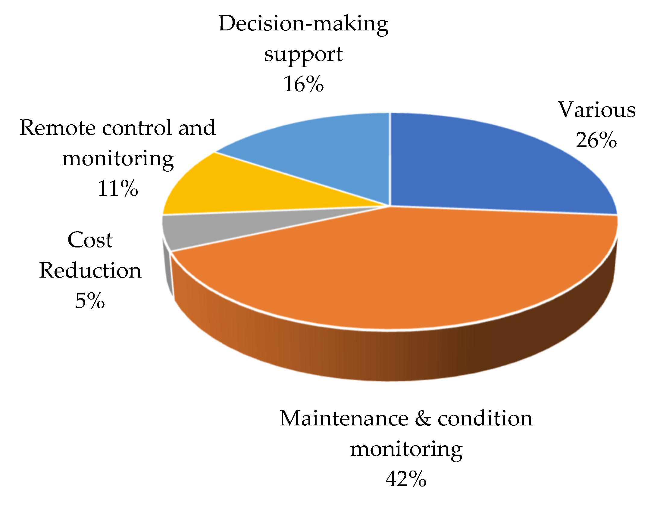
The most common ship system being modelled is an electric power system or one of its components, as found in 23% of the reviewed case-studies, followed by the propulsion system and ship hull structure modelled in 18% of the reviewed publications, as shown in Figure 6. SDTs have been found mostly used for maintenance and condition monitoring, as proposed in 42% of the reviewed literature and shown in Figure 7.
6. Discussion
As presented in the paper, the digital twin of a ship, an SDT, is an evolving concept that can be a useful supplement in the control of the individual ship processes, or can improve the overall control strategy and ship management. As such, an SDT is becoming an important part in both shipbuilding and the ship’s exploitation. However, it also presents challenges in all aspects, from data acquisition and communication, modelling and simulation, to the implementation of the concept and standards establishment.
It can be noted how SDTs should stream towards flexible structures that could be extended and upgraded over time, and how further research should be performed in each direction of the SDT formulation process in order to improve the concept, explore the methods, and expand the application area.
Further research planed by the authors is oriented towards modelling and prediction of ship motion and hull stress induced by waves. The authors of the paper intend to develop a digital twin of a ship for ship hull condition monitoring and fatigue prediction based on full-scale measurements and also to model the relationship between waves and ship motion. The measurements have already been performed in both case studies.
7. Conclusions
Over 100 published papers on the topic of a digital twin (DT) are considered in order to investigate the use of DTs in maritime industry, and 51 of those serve as references for writing this paper, while 19 papers are found dedicated to the digital twins of a ship or ship subsystems. The analysis presented in this paper suggests a continuous positive trend in the number of SDT-related publications in the last four years that justifies the research of an SDT concept.
One of the goals of the work presented in this paper is to investigate the steps of the SDT formulation process and to make a review of the methods used in the process, communication protocols, as well as to describe the applications in maritime industry. An iterative four-step procedure for creating an SDT is proposed, with data acquisition, data processing, modelling, and validation of the model making those steps. The steps proposed in this paper for the SDT formulation are justified as those steps can be related to the steps found in most (52%) of the reviewed papers, and 3 out of 4 steps can be found used in 95% of the reviewed publications.
Methods used to form DT models are various, ranging from traditional physical-based mathematical modelling to modern data-based modelling approaches such as artificial neural networks. As an SDT concept relies on data, it would be expected for data-based modelling, and especially artificial intelligence, to take over the prime lead in this area. However, classical physical-based modelling using mathematical modelling and FEM methods were used in 44% of the cases analysed, while data-based modelling was used in 30% of the cases. The results suggest the variability of the methods used and case dependency; hence, the modelling method is chosen based on the application purpose, possibilities, and case-based constraints.
Based on the review presented in the paper, it can be concluded that the ship’s digital twin can be usefully and efficiently exploited in terms of maintenance scheduling, predictive maintenance, fault prediction, real-time fault detection, optimisation of the processes onboard the ship, e.g., fuel consumption reduction, pollution impact reduction, ship’s hull condition monitoring, and overall cost reduction, where the most common SDT applications focus on condition monitoring and condition-based maintenance, as found in 42% of the cases reviewed. The analysis showed that the propulsion system (18%), ships structure (18%), and electrical systems (23%) are the most common case-studies.
Communication standards and protocols used in the SDT concept are well-known and verified by use in various industries through the past twenty years. A commonly used reference model for communication standards comparison is the ISO OSI reference model according to which some of the standards, such as the CIP protocol family, EtherCAT, and MTConnect, cover multiple layers of the reference model. Considering the communication standards available, it can be concluded that one of the major challenges regarding the use of SDTs is the real-time communication with the real object.
Author Contributions
Conceptualization, N.A., P.M. and M.K.; methodology, N.A. and P.M.; formal analysis, P.M. and M.K.; investigation, N.A.; resources, N.A. and P.M.; writing—original draft preparation, N.A.; writing—review and editing, P.M., M.K. and N.A.; visualization, N.A.; supervision, P.M. All authors have read and agreed to the published version of the manuscript.
Funding
This research received no external funding. APC was funded by the Faculty of Maritime Studies, University of Split, Croatia.
Institutional Review Board Statement
Not applicable.
Informed Consent Statement
Not applicable.
Data Availability Statement
Not applicable.
Conflicts of Interest
The authors declare no conflict of interest.
References
- Fonseca, Í.A.; Gaspar, H.M. Challenges When Creating a Cohesive Digital Twin Ship: A Data Modelling Perspective. Ship Technol. Res. 2021, 68, 70–83. [Google Scholar] [CrossRef]
- Šoda, J.; Majić, M.; Vujović, I.; Sorić, B. An Overview on a Future Trends and Smart Technologies in Maritime. In Proceedings of the 8th International Maritime Science Conference, Budva, Montenegro, 11–12 April 2019. [Google Scholar]
- Lee, J.; Bagheri, B.; Kao, H.-A. A Cyber-Physical Systems Architecture for Industry 4.0-Based Manufacturing Systems. Manuf. Lett. 2015, 3, 18–23. [Google Scholar] [CrossRef]
- Wan, J.; Canedo, A.; Al Faruque, M.A. Functional Model-Based Design Methodology for Automotive Cyber-Physical Systems. IEEE Syst. J. 2017, 11, 2028–2039. [Google Scholar] [CrossRef]
- Alam, K.M.; Sopena, A.; El Saddik, A. Design and Development of a Cloud Based Cyber-Physical Architecture for the Internet-of-Things. In Proceedings of the 2015 IEEE International Symposium on Multimedia (ISM), Miami, FL, USA, 14–16 December 2015; IEEE: Piscataway, NJ, USA, 2015; pp. 459–464. [Google Scholar]
- Alam, K.M.; El Saddik, A. C2PS: A Digital Twin Architecture Reference Model for the Cloud-Based Cyber-Physical Systems. IEEE Access 2017, 5, 2050–2062. [Google Scholar] [CrossRef]
- Saracco, R. Digital Twins: Bridging Physical Space and Cyberspace. Computer 2019, 52, 58–64. [Google Scholar] [CrossRef]
- Coraddu, A.; Oneto, L.; Baldi, F.; Cipollini, F.; Atlar, M.; Savio, S. Data-Driven Ship Digital Twin for Estimating the Speed Loss Caused by the Marine Fouling. Ocean Eng. 2019, 186, 106063. [Google Scholar] [CrossRef]
- Danielsen-Haces, A. Digital Twin Development. Master’s Thesis, Norwegian University of Science and Technology, Trondheim, Norway, 2018. [Google Scholar]
- Liu, M.; Zhou, Q.; Wang, X.; Yu, C.; Kang, M. Voyage Performance Evaluation Based on a Digital Twin Model. IOP Conf. Ser. Mater. Sci. Eng. 2020, 929, 012027. [Google Scholar] [CrossRef]
- Anyfantis, K.N. An Abstract Approach toward the Structural Digital Twin of Ship Hulls: A Numerical Study Applied to a Box Girder Geometry. Proc. Inst. Mech. Eng. Part M J. Eng. Marit. Environ. 2021, 235, 718–736. [Google Scholar] [CrossRef]
- VanDerHorn, E.; Mahadevan, S. Digital Twin: Generalization, Characterization and Implementation. Decis. Support Syst. 2021, 145, 113524. [Google Scholar] [CrossRef]
- Bekker, A. Exploring the Blue Skies Potential of Digital Twin Technology for a Polar Supply and Research Vessel. In Proceedings of the 13th International Marine Design Conference, Helsinki, Finland, 10–14 June 2018. [Google Scholar]
- Major, P.; Li, G.; Zhang, H.; Hildre, H.P. Real-Time Digital Twin Of Research Vessel For Remote Monitoring. In Proceedings of the International Conference on Modelling and Simulation (ECMS 2021), Virtual, 31 May–2 June 2021; pp. 159–164. [Google Scholar]
- Bondarenko, O.; Fukuda, T. Development of a Diesel Engine’s Digital Twin for Predicting Propulsion System Dynamics. Energy 2020, 196, 117126. [Google Scholar] [CrossRef]
- Hulkkonen, T.; Manderbacka, T.; Sugimoto, K. Digital Twin for Monitoring Remaining Fatigue Life of Critical Hull Structures. In Proceedings of the 18th Conference on Computer Applications and Information Technology in the Maritime Industries (COMPIT2019), Tullamore, Ireland, 25–27 March 2019. [Google Scholar]
- Perabo, F.; Park, D.; Zadeh, M.K.; Smogeli, O.; Jamt, L. Digital Twin Modelling of Ship Power and Propulsion Systems: Application of the Open Simulation Platform (OSP). In Proceedings of the 2020 IEEE 29th International Symposium on Industrial Electronics (ISIE), Delft, The Netherlands, 17–19 June 2020; IEEE: Piscataway, NJ, USA, 2020; pp. 1265–1270. [Google Scholar]
- Radan, D. Integrated Control of Marine Electrical Power Systems. Ph.D. Thesis, Norwegian University of Science and Technology, Trondheim, Norway, 2008. [Google Scholar]
- Bondarenko, O.; Kitagawa, Y. Real-time propulsion plant simulation and hardware in the loop (HIL) implementation of microprocessor engine governor. In Proceedings of the 13th International Conference on Engine Room Simulators (ICERS2013), Odessa, Ukraine, 20–21 September 2017. [Google Scholar]
- Johansen, S.S.; Nejad, A.R. On Digital Twin Condition Monitoring Approach for Drivetrains in Marine Applications. In Proceedings of the Volume 10: Ocean Renewable Energy, Glasgow, UK, 9–14 June 2019; American Society of Mechanical Engineers: New York, NY, USA, 2019; p. V010T09A013. [Google Scholar]
- Manngård, M.; Lund, W.; Björkqvist, J. Using Digital Twin Technology to Ensure Data Quality in Transport Systems. In Proceedings of the 8th Transport Research Arena (TRA2020): Rethinking Transport towards Clean and Inclusive Mobility, Helsinki, Finland, 27–30 April 2020. [Google Scholar]
- Galeev, R.E.; Soloviev, A.V.; Fedosenko, Y.S. Modeling and Visualization of the Forecast Trajectory for the Decision Support System for Controlling the Movement of a River Displacement Vessel. J. Phys. Conf. Ser. 2021, 2131, 032033. [Google Scholar] [CrossRef]
- Arrichiello, V.; Gualeni, P. Systems Engineering and Digital Twin: A Vision for the Future of Cruise Ships Design, Production and Operations. Int. J. Interact. Des. Manuf. 2020, 14, 115–122. [Google Scholar] [CrossRef]
- Fonseca, I.A.; Gaspar, H.M. Fundamentals Of Digital Twins Applied To A Plastic Toy Boat And A Ship Scale Model. In Proceedings of the ECMS Conference on Modelling and Simulation (ECMS 2020), Wildau, Germany, 9–12 June 2020; pp. 207–213. [Google Scholar]
- Dufour, C.; Soghomonian, Z.; Li, W. Hardware-in-the-Loop Testing of Modern On-Board Power Systems Using Digital Twins. In Proceedings of the 2018 International Symposium on Power Electronics, Electrical Drives, Automation and Motion (SPEEDAM), Amalfi, Italy, 20–22 June 2018; pp. 118–123. [Google Scholar]
- Grinek, A.; Boychuk, I.; Fishenko, A.M.; Savosteenko, N.; Gerasimenko, O.N. Investigation of the Operation of a Ship’s Synchronous Generator Based on a Numerical Model. J. Phys. Conf. Ser. 2021, 2061, 012004. [Google Scholar] [CrossRef]
- Wunderlich, A.; Booth, K.; Santi, E. Hybrid Analytical and Data-Driven Modeling Techniques for Digital Twin Applications. In Proceedings of the 2021 IEEE Electric Ship Technologies Symposium (ESTS), Arlington, VA, USA, 3–6 August 2021; pp. 1–7. [Google Scholar]
- Boschert, S.; Rosen, R. Digital Twin—The Simulation Aspect. In Mechatronic Futures; Hehenberger, P., Bradley, D., Eds.; Springer International Publishing: Cham, Switzerland, 2016; pp. 59–74. ISBN 978-3-319-32154-7. [Google Scholar]
- Wen-hao, W.; Guo-bing, C.; Zi-chun, Y. The Application and Challenge of Digital Twin Technology in Ship Equipment. J. Phys. Conf. Ser. 2021, 1939, 012068. [Google Scholar] [CrossRef]
- Singh, M.; Fuenmayor, E.; Hinchy, E.P.; Qiao, Y.; Murray, N.; Devine, D. Digital Twin: Origin to Future. Appl. Syst. Innov. 2021, 4, 36. [Google Scholar] [CrossRef]
- Kosacka-Olejnik, M.; Kostrzewski, M.; Marczewska, M.; Mrówczyńska, B.; Pawlewski, P. How Digital Twin Concept Supports Internal Transport Systems?—Literature Review. Energies 2021, 14, 4919. [Google Scholar] [CrossRef]
- Errandonea, I.; Beltrán, S.; Arrizabalaga, S. Digital Twin for Maintenance: A Literature Review. Comput. Ind. 2020, 123, 103316. [Google Scholar] [CrossRef]
- Semeraro, C.; Lezoche, M.; Panetto, H.; Dassisti, M. Digital Twin Paradigm: A Systematic Literature Review. Comput. Ind. 2021, 130, 103469. [Google Scholar] [CrossRef]
- Erikstad, S.O. Design Patterns for Digital Twin Solutions in Marine Systems Design and Operations. In Proceedings of the Conference on Computer Applications and Information Technology in the Maritime Industries (COMPIT), Pavone, Italy, 14–16 May 2018. [Google Scholar]
- Glaessgen, E.; Stargel, D. The Digital Twin Paradigm for Future NASA and U.S. Air Force Vehicles. In Proceedings of the 53rd AIAA/ASME/ASCE/AHS/ASC Structures, Structural Dynamics and Materials Conference, Honolulu, HI, USA, 23–26 April 2012. [Google Scholar]
- Defense Acquisition Glossary. Available online: https://www.dau.edu/glossary/Pages/Glossary.aspx (accessed on 25 May 2022).
- Hause, M. The Digital Twin Throughout the SE Lifecycle. In SNAME Maritime Convention; OnePetro: Richardson, TX, USA, 2019; Volume 29, pp. 203–217. [Google Scholar] [CrossRef]
- Pang, T.Y.; Pelaez Restrepo, J.D.; Cheng, C.-T.; Yasin, A.; Lim, H.; Miletic, M. Developing a Digital Twin and Digital Thread Framework for an ‘Industry 4.0’ Shipyard. Appl. Sci. 2021, 11, 1097. [Google Scholar] [CrossRef]
- Functional Mock-Up Interface. Available online: https://fmi-standard.org/ (accessed on 25 May 2022).
- Diaz, A.; Saltares, R.; Rodriguez, C.; Nunez, R.F.; Ortiz-Rivera, E.I.; Gonzalez-Llorente, J. Induction Motor Equivalent Circuit for Dynamic Simulation. In Proceedings of the 2009 IEEE International Electric Machines and Drives Conference, Miami, FL, USA, 3–6 May 2009; pp. 858–863. [Google Scholar]
- Katalinić, M. Data based modelling of the mean wave period in the adriatic sea. Trans. Marit. Sci. 2017, 11, 308. [Google Scholar]
- Schroeder, G.N.; Steinmetz, C.; Rodrigues, R.N.; Rettberg, A.; Pereira, C.E. Digital Twin Connectivity Topologies. IFAC-Pap. 2021, 54, 737–742. [Google Scholar] [CrossRef]
- Lu, Y.; Xu, X. A digital twin reference model for smart manufacturing. In Proceedings of the 48th International Conference on Computers and Industrial Engineering CIE 2018, Auckland, New Zealand, 2–5 December 2018. [Google Scholar]
- Lim, K.Y.H.; Zheng, P.; Chen, C.-H. A State-of-the-Art Survey of Digital Twin: Techniques, Engineering Product Lifecycle Management and Business Innovation Perspectives. J. Intell. Manuf. 2020, 31, 1313–1337. [Google Scholar] [CrossRef]
- Liu, M.; Fang, S.; Dong, H.; Xu, C. Review of Digital Twin about Concepts, Technologies, and Industrial Applications. J. Manuf. Syst. 2021, 58, 346–361. [Google Scholar] [CrossRef]
- Qi, Q.; Tao, F.; Hu, T.; Anwer, N.; Liu, A.; Wei, Y.; Wang, L.; Nee, A.Y.C. Enabling Technologies and Tools for Digital Twin. J. Manuf. Syst. 2021, 58, 3–21. [Google Scholar] [CrossRef]
- Hofmann, W.; Branding, F. Implementation of an IoT- and Cloud-Based Digital Twin for Real-Time Decision Support in Port Operations. IFAC-Papers 2019, 52, 2104–2109. [Google Scholar] [CrossRef]
- Liu, Q.; Liu, B.; Wang, G.; Zhang, C. A Comparative Study on Digital Twin Models. In Proceedings of the AIP Conference Proceedings 2073, Wuhan, China, 19–20 January 2019. [Google Scholar]
- Minerva, R.; Lee, G.M.; Crespi, N. Digital Twin in the IoT Context: A Survey on Technical Features, Scenarios, and Architectural Models. Proc. IEEE 2020, 108, 1785–1824. [Google Scholar] [CrossRef]
- Tofte, B.L.; Vennemann, O.; Mitchell, F.; Millington, N.; McGuire, L. How Digital Technology and Standardisation Can Improve Offshore Operations. In Proceedings of the Offshore Technology Conference (OTC), Houston, TX, USA, 6–9 May 2019. [Google Scholar]
- Ibrion, M.; Paltrinieri, N.; Nejad, A.R. Learning from Failures in Cruise Ship Industry: The Blackout of Viking Sky in Hustadvika, Norway. Eng. Fail. Anal. 2021, 125, 105355. [Google Scholar] [CrossRef]
Figure 1.
SDT concept as an iterative process.

Figure 2.
Communication layers and protocols.

Figure 3.
Number of SDT publications in the last four years.

Figure 4.
The use of the proposed steps in reviewed literature.

Figure 5.
Modelling methods review.

Figure 6.
Percentage of the ship’s systems modelled in reviewed papers.

Figure 7.
Percentage of the application purposes as presented in reviewed papers.


Table 1.
The review analysis of DT models, formulation steps, methods, and applications.
| Paper (Author, Year) | Model | Steps | Methods | Application |
|---|---|---|---|---|
| Radan, D., 2008, [18] | Ship electric power system | I, III, II, IV | Mathematical modelling | Various |
| Dufour, C. et al., 2018, [25] | Ship electric power system | I, II, III | MBD, HIL | Maintenance and condition monitoring |
| Danielsen-Haces, A., 2018, [9] | Electric propulsion system | I, II, III, IV | ANN | Maintenance and condition monitoring |
| Bekker, A., 2018, [13] | Behaviouristic model of a ship | I, II, III | DDM, Statistics | Maintenance and condition monitoring |
| Coraddu, A. et al., 2019, [8] | Propulsion system and ship hydrodynamics | I, II, III, IV | ANN, DDM | Maintenance and condition monitoring |
| Arrichiello, V. et al., 2019, [23] | Hull structure and machinery | I, III, II | MBSE | Decision-making support |
| Hulkkonen, T. et al., 2019, [16] | Ship structure (balcony opening) | I, II, III | FEM | Maintenance and condition monitoring |
| Johansen, S. et al., 2019, [20] | Ship drivetrain | I, II, III, IV | FEM | Maintenance and condition monitoring |
| Bondarenko, O. et al., 2020, [15] | Diesel engine | I, III, II, IV | Mathematical modelling, HIL, CMV | Various |
| Fonseca, I. et al., 2020, [24] | Ship hull and propulsion system behavioural model | I, II, III | BEM | Remote control and monitoring |
| Manngård, M. et al., 2020, [21] | Heat exchanger of a diesel engine | I, III, II, IV | Mathematical modelling, Statistics, FEM | Various |
| Liu, M. et al., 2020, [10] | Ship speed and fuel consumption | I, II, III, IV | GBM, ANN | Various |
| Perabo, F. et al., 2020, [17] | Ship power and propulsion system | I, III, II, IV | Mathematical modelling | Cost reduction |
| Anyfantis, K. N., 2021, [11] | Ship hull structure | I, II, III, IV | FEM, ANN | Maintenance and condition monitoring |
| Major, P. et al., 2021, [14] | Ship and ship crane | I, II, III, IV | DDM, HIL | Remote control and monitoring |
| Galeev, R. E. et al., 2021, [22] | Ship trajectory | I, II, III | Mathematical modelling | Decision-making support |
| Grinek, A. V., et al., 2021, [26] | Ship synchronous generator | I, II, III | FEM | Maintenance and condition monitoring |
| Wunderlich, A. et al., 2021, [27] | Boost converter as a part of ship power system | II, III | GBM | Various |
| VanDerHorn, E. et al., 2021, [12] | Ship hull structure | I, II, III | FEM, DDM | Decision-making support |
Publisher’s Note: MDPI stays neutral with regard to jurisdictional claims in published maps and institutional affiliations. |
© 2022 by the authors. Licensee MDPI, Basel, Switzerland. This article is an open access article distributed under the terms and conditions of the Creative Commons Attribution (CC BY) license (https://creativecommons.org/licenses/by/4.0/).
Share and Cite
MDPI and ACS Style
Assani, N.; Matić, P.; Katalinić, M. Ship’s Digital Twin—A Review of Modelling Challenges and Applications. Appl. Sci. 2022, 12, 6039. https://doi.org/10.3390/app12126039
AMA Style
Assani N, Matić P, Katalinić M. Ship’s Digital Twin—A Review of Modelling Challenges and Applications. Applied Sciences. 2022; 12(12):6039. https://doi.org/10.3390/app12126039
Chicago/Turabian StyleAssani, Nur, Petar Matić, and Marko Katalinić. 2022. "Ship’s Digital Twin—A Review of Modelling Challenges and Applications" Applied Sciences 12, no. 12: 6039. https://doi.org/10.3390/app12126039
Note that from the first issue of 2016, this journal uses article numbers instead of page numbers. See further details here.