
Systematic Review on Human Skin-Compatible Wearable Photoplethysmography Sensors

 , ,
, ,
Abstract
:1. Introduction
2. Methodology
3. Photoplethysmography (PPG) Sensor and Its Application
3.1. Mechanism of PPG Sensor
3.2. Applications of PPG Sensor
4. Human Skin-Compatible PPG Sensors
4.1. Silicon Photodiodes
4.2. Other Inorganic Photodiodes
4.3. Organic Photodiodes
5. Conclusions
Author Contributions
Funding
Institutional Review Board Statement
Informed Consent Statement
Data Availability Statement
Conflicts of Interest
References
- Ghamari, M. A Review on Wearable Photoplethysmography Sensors and Their Potential Future Applications in Health Care. Int. J. Biosens. Bioelectron. 2018, 4, 195–202. [Google Scholar] [CrossRef] [PubMed] [Green Version]
- Rawassizadeh, R.; Price, B.A.; Petre, M. Wearables: Has the Age of Smartwatches Finally Arrived? Commun. ACM 2014, 58, 45–47. [Google Scholar] [CrossRef]
- Wei, J. How Wearables Intersect with the Cloud and the Internet of Things: Considerations for the Developers of Wearables. IEEE Consum. Electron. Mag. 2014, 3, 53–56. [Google Scholar] [CrossRef]
- Riazul Islam, S.M.; Kwak, D.; Humaun Kabir, M.; Hossain, M.; Kwak, K.-S. The Internet of Things for Health Care: A Comprehensive Survey. IEEE Access 2015, 3, 678–708. [Google Scholar] [CrossRef]
- Martins, A.F.; Santos, D.F.S.; Perkusich, A.; Almeida, H.O. UPnP and IEEE 11073: Integrating Personal Health Devices in Home Networks. In Proceedings of the 2014 IEEE 11th Consumer Communications and Networking Conference (CCNC), Las Vegas, NV, USA, 10–13 January 2014. [Google Scholar]
- Jeong, S.; Kim, S.; Kim, D.; Youn, C.-H.; Kim, Y.-W. A Personalized Healthcare System for Chronic Disease Care in Home-Hospital Cloud Environments. In Proceedings of the 2013 International Conference on ICT Convergence (ICTC), Jeju, Korea, 14–16 October 2013; pp. 371–376. [Google Scholar]
- Adamson, P.B.; Abraham, W.T.; Aaron, M.; Aranda, J.M.; Bourge, R.C.; Smith, A.; Stevenson, L.W.; Bauman, J.G.; Yadav, J.S. CHAMPION∗ Trial Rationale and Design: The Long-Term Safety and Clinical Efficacy of a Wireless Pulmonary Artery Pressure Monitoring System. J. Card. Fail. 2011, 17, 3–10. [Google Scholar] [CrossRef] [PubMed]
- Mukhopadhyay, S.C. Wearable Sensors for Human Activity Monitoring: A Review. IEEE Sens. J. 2015, 15, 1321–1330. [Google Scholar] [CrossRef]
- Gao, W.; Emaminejad, S.; Nyein, H.Y.Y.; Challa, S.; Chen, K.; Peck, A.; Fahad, H.M.; Ota, H.; Shiraki, H.; Kiriya, D.; et al. Fully Integrated Wearable Sensor Arrays for Multiplexed in Situ Perspiration Analysis. Nature 2016, 529, 509–514. [Google Scholar] [CrossRef] [PubMed] [Green Version]
- Chan, M.; Estève, D.; Fourniols, J.-Y.; Escriba, C.; Campo, E. Smart Wearable Systems: Current Status and Future Chal lenges. Artif. Intell. Med. 2012, 56, 137–156. [Google Scholar] [CrossRef]
- Yang, G.; Pang, G.; Pang, Z.; Gu, Y.; Mantysalo, M.; Yang, H. Non-Invasive Flexible and Stretchable Wearable Sensors with Nano-Based Enhancement for Chronic Disease Care. IEEE Rev. Biomed. Eng. 2019, 12, 34–71. [Google Scholar] [CrossRef]
- Ghamari, M.; Janko, B.; Sherratt, R.; Harwin, W.; Piechockic, R.; Soltanpur, C. A Survey on Wireless Body Area Networks for EHealthcare Systems in Residential Environments. Sensors 2016, 16, 831. [Google Scholar] [CrossRef] [Green Version]
- Park, S.; Jayaraman, S. Enhancing the Quality of Life through Wearable Technology. IEEE Eng. Med. Biol. Mag. 2003, 22, 41–48. [Google Scholar] [CrossRef] [PubMed]
- Liu, Y.; Wang, H.; Zhao, W.; Zhang, M.; Qin, H.; Xie, Y. Flexible, Stretchable Sensors for Wearable Health Monitoring: Sensing Mechanisms, Materials, Fabrication Strategies and Features. Sensors 2018, 18, 645. [Google Scholar] [CrossRef] [Green Version]
- Parak, J.; Korhonen, I. Evaluation of Wearable Consumer Heart Rate Monitors Based on Photopletysmography. In Proceedings of the 2014 36th Annual International Conference of the IEEE Engineering in Medicine and Biology Society, Chicago, IL, USA, 26–30 August 2014; pp. 3670–3673. [Google Scholar]
- McCombie, D.; Asada, H.; Reisner, A. Identification of Vascular Dynamics and Estimation of the Cardiac Output Waveform from Wearable PPG Sensors. In Proceedings of the 2005 IEEE Engineering in Medicine and Biology 27th Annual Conference, Shanghai, China, 17–18 January 2006; pp. 3490–3493. [Google Scholar]
- Cha, J.; Choi, H.; Shin, J.; Lee, K. Unconstrained Respiration and Heart Rate Monitoring System Based on a PPG Pillow during Sleep. In Proceedings of the 2008 30th Annual International Conference of the IEEE Engineering in Medicine and Biology Society, Vancouver, BC, Canada, 20–25 August 2008; pp. 3224–3226. [Google Scholar]
- Rozi, R.M.; Usman, S.; Ali, M.A.M.; Reaz, M.B.I. Second Derivatives of Photoplethysmography (PPG) for Estimating Vascular Aging of Atherosclerotic Patients. In Proceedings of the 2012 IEEE-EMBS Conference on Biomedical Engineering and Sciences, Langkawi, Malaysia, 17–19 December 2012. [Google Scholar]
- Zakaria, H.; Mengko, T.L.R. Endothelial Dysfunction Assessment by Finger Photoplethysmogram. In Proceedings of the 2017 6th International Conference on Electrical Engineering and Informatics (ICEEI), Langkawi, Malaysia, 25–27 November 2017; pp. 1–4. [Google Scholar]
- Allen, J.; Frame, J.R.; Murray, A. Microvascular Blood Flow and Skin Temperature Changes in the Fingers Following a Deep Inspiratory Gasp. Physiol. Meas. 2002, 23, 365–373. [Google Scholar] [CrossRef]
- Servati, A.; Zou, L.; Wang, Z.; Ko, F.; Servati, P. Novel Flexible Wearable Sensor Materials and Signal Processing for Vital Sign and Human Activity Monitoring. Sensors 2017, 17, 1622. [Google Scholar] [CrossRef] [Green Version]
- Slapničar, G.; Luštrek, M.; Marinko, M. Continuous Blood Pressure Estimation from PPG Signal. Informatica 2018, 42, 10. [Google Scholar]
- Zhang, Q.; Kadefors, R. A Non-Invasive Measure of Changes in Blood flow in the Human Anterior Tibial Muscle. Eur. J. Appl. Physiol. 2001, 84, 448–452. [Google Scholar] [CrossRef] [PubMed]
- Wu, H.-T.; Lee, C.-H.; Liu, A.-B. Assessment of Endothelial Function Using Arterial Pressure Signals. J. Signal Process. Syst. 2011, 64, 223–232. [Google Scholar] [CrossRef]
- Matsumura, K.; Rolfe, P.; Lee, J.; Yamakoshi, T. IPhone 4s Photoplethysmography: Which Light Color Yields the Most Accurate Heart Rate and Normalized Pulse Volume Using the IPhysioMeter Application in the Presence of Motion Artifact? PLoS ONE 2014, 9, e91205. [Google Scholar] [CrossRef] [PubMed]
- Asada, H.H.; Shaltis, P.; Reisner, A.; Rhee, S.; Hutchinson, R.C. Mobile Monitoring with Wearable Photoplethysmographic Biosensors. IEEE Eng. Med. Biol. Mag. 2003, 22, 28–40. [Google Scholar] [CrossRef] [Green Version]
- Xu, S.; Zhang, Y.; Jia, L.; Mathewson, K.E.; Jang, K.-I.; Kim, J.; Fu, H.; Huang, X.; Chava, P.; Wang, R.; et al. Soft Microfluidic Assemblies of Sensors, Circuits, and Radios for the Skin. Science 2014, 344, 70–74. [Google Scholar] [CrossRef]
- Huang, X.; Liu, Y.; Chen, K.; Shin, W.-J.; Lu, C.-J.; Kong, G.-W.; Patnaik, D.; Lee, S.-H.; Cortes, J.F.; Rogers, J.A. Stretchable, Wireless Sensors and Functional Substrates for Epidermal Characterization of Sweat. Small 2014, 10, 3083–3090. [Google Scholar] [CrossRef] [PubMed]
- Kim, J.; Banks, A.; Cheng, H.; Xie, Z.; Xu, S.; Lee, J.W.; Liu, Z.; Gutruf, P.; Huang, X.; Wei, P.; et al. Epidermal Electronics with Advanced Capabilities in Near—Field Communication. Small 2015, 11, 906–912. [Google Scholar] [CrossRef] [PubMed]
- Kim, J.; Salvatore, G.A.; Araki, H.; Chiarelli, A.M.; Xie, Z.; Banks, A.; Sheng, X.; Liu, Y.; Lee, J.W.; Jang, K.-I.; et al. Battery-Free, Stretchable Optoelectronic Systems for Wireless Optical Characterization of the Skin. Sci. Adv. 2016, 2, e1600418. [Google Scholar] [CrossRef] [PubMed] [Green Version]
- Kim, J.; Gutruf, P.; Chiarelli, A.M.; Heo, S.Y.; Cho, K.; Xie, Z.; Banks, A.; Han, S.; Jang, K.-I.; Lee, J.W.; et al. Miniaturized Battery-Free Wireless Systems for Wearable Pulse Oximetry. Adv. Funct. Mater. 2017, 27, 1604373. [Google Scholar] [CrossRef] [PubMed] [Green Version]
- Li, H.; Xu, Y.; Li, X.; Chen, Y.; Jiang, Y.; Zhang, C.; Lu, B.; Wang, J.; Ma, Y.; Chen, Y.; et al. Epidermal Inorganic Optoelectronics for Blood Oxygen Measurement. Adv. Healthc. Mater. 2017, 6, 1601013. [Google Scholar] [CrossRef] [PubMed]
- Kim, J.; Kim, N.; Kwon, M.; Lee, J. Attachable Pulse Sensors Integrated with Inorganic Optoelectronic Devices for Monitoring Heart Rates at Various Body Locations. ACS Appl. Mater. Interfaces 2017, 9, 25700–25705. [Google Scholar] [CrossRef]
- Kim, T.-H.; Lee, C.-S.; Kim, S.; Hur, J.; Lee, S.; Shin, K.W.; Yoon, Y.-Z.; Choi, M.K.; Yang, J.; Kim, D.-H.; et al. Fully Stretchable Optoelectronic Sensors Based on Colloidal Quantum Dots for Sensing Photoplethysmographic Signals. ACS Nano 2017, 11, 5992–6003. [Google Scholar] [CrossRef]
- Polat, E.O.; Mercier, G.; Nikitskiy, I.; Puma, E.; Galan, T.; Gupta, S.; Montagut, M.; Piqueras, J.J.; Bouwens, M.; Durduran, T.; et al. Flexible Graphene Photodetectors for Wearable Fitness Monitoring. Sci. Adv. 2019, 5, eaaw7846. [Google Scholar] [CrossRef] [PubMed] [Green Version]
- Yokota, T.; Zalar, P.; Kaltenbrunner, M.; Jinno, H.; Matsuhisa, N.; Kitanosako, H.; Tachibana, Y.; Yukita, W.; Koizumi, M.; Someya, T. Ultraflexible Organic Photonic Skin. Sci. Adv. 2016, 2, e1501856. [Google Scholar] [CrossRef] [PubMed] [Green Version]
- Park, S.; Fukuda, K.; Wang, M.; Lee, C.; Yokota, T.; Jin, H.; Jinno, H.; Kimura, H.; Zalar, P.; Matsuhisa, N.; et al. Ultraflexible Near-Infrared Organic Photodetectors for Conformal Photoplethysmogram Sensors. Adv. Mater. 2018, 30, 1802359. [Google Scholar] [CrossRef]
- Khan, Y.; Han, D.; Pierre, A.; Ting, J.; Wang, X.; Lochner, C.M.; Bovo, G.; Yaacobi-Gross, N.; Newsome, C.; Wilson, R.; et al. A Flexible Organic Reflectance Oximeter Array. Proc. Natl. Acad. Sci. USA 2018, 115, E11015–E11024. [Google Scholar] [CrossRef] [PubMed] [Green Version]
- Khan, Y.; Han, D.; Ting, J.; Ahmed, M.; Nagisetty, R.; Arias, A.C. Organic Multi-Channel Optoelectronic Sensors for Wearable Health Monitoring. IEEE Access 2019, 7, 128114–128124. [Google Scholar] [CrossRef]
- Xu, H.; Liu, J.; Zhang, J.; Zhou, G.; Luo, N.; Zhao, N. Flexible Organic/Inorganic Hybrid Near-Infrared Photoplethysmogram Sensor for Cardiovascular Monitoring. Adv. Mater. 2017, 29, 1700975. [Google Scholar] [CrossRef] [PubMed]
- Lee, H.; Kim, E.; Lee, Y.; Kim, H.; Lee, J.; Kim, M.; Yoo, H.-J.; Yoo, S. Toward All-Day Wearable Health Monitoring: An Ultralow-Power, Reflective Organic Pulse Oximetry Sensing Patch. Sci. Adv. 2018, 4, eaas9530. [Google Scholar] [CrossRef] [Green Version]
- Kim, H.; Kang, T.-H.; Ahn, J.; Han, H.; Park, S.; Kim, S.J.; Park, M.-C.; Paik, S.; Hwang, D.K.; Yi, H.; et al. Spirally Wrapped Carbon Nanotube Microelectrodes for Fiber Optoelectronic Devices beyond Geometrical Limitations toward Smart Wearable E-Textile Applications. ACS Nano 2020, 14, 17213–17223. [Google Scholar] [CrossRef] [PubMed]
- Abay, T.Y. Reflectance Photoplethysmography as Noninvasive Monitoring of Tissue Blood Perfusion. IEEE Trans. Biomed. Eng. 2015, 62, 9. [Google Scholar] [CrossRef]
- Allen, J. Photoplethysmography and Its Application in Clinical Physiological Measurement. Physiol. Meas. 2007, 28, R1-39. [Google Scholar] [CrossRef] [Green Version]
- Dorlas, J.C.; Mahieu, H.F. Photoelectric Plethysmography-Some Fundamental Aspects of the Reflection and Transmission Method. Clin. Phys. Physiol. Meas. 1981, 2, 205–215. [Google Scholar]
- Ovadia-Blechman, Z.; Gino, O.; Dandeker, L.; Sheffer, N.; Baltaxe, E.; Aharonson, V. The Feasibility of Flat, Portable and Wireless Device for Non-Invasive Peripheral Oxygenation Measurement over the Entire Body. J. Biomed. Sci. Eng. 2016, 9, 147–159. [Google Scholar] [CrossRef] [Green Version]
- Buchs, A.; Slovik, Y.; Rapoport, M.; Rosenfeld, C.; Khanokh, B.; Nitzan, M. Right-Left Correlation of the Sympathetically Induced Fluctuations of Photoplethysmographic Signal in Diabetic and Non-Diabetic Subjects. Med. Biol. Eng. Comput. 2005, 43, 252–257. [Google Scholar] [CrossRef]
- Allen, J.; Oates, C.P.; Lees, T.A.; Murray, A. Photoplethysmography Detection of Lower Limb Peripheral Arterial Occlusive Disease: A Comparison of Pulse Timing, Amplitude and Shape Characteristics. Physiol. Meas. 2005, 26, 811–821. [Google Scholar] [CrossRef]
- Lochner, C.M.; Khan, Y.; Pierre, A.; Arias, A.C. All-Organic Optoelectronic Sensor for Pulse Oximetry. Nat. Commun. 2014, 5, 5745. [Google Scholar] [CrossRef] [Green Version]
- Zijlstra, W.G.; Buursma, A. Spectrophotometry of Hemoglobin: Absorption Spectra of Bovine Oxyhemoglobin, Deoxyhemoglobin, Carboxyhemoglobin, and Methemoglobin. Comp. Biochem. Physiol. B Biochem. Mol. Biol. 1997, 118, 743–749. [Google Scholar] [CrossRef]
- Roggan, A.; Friebel, M.; Dörschel, K.; Hahn, A.; Müller, G. Optical Properties of Circulating Human Blood in the Wavelength Range 400–2500 Nm. J. Biomed. Opt. 1999, 4, 36. [Google Scholar] [CrossRef] [Green Version]
- Gharahbaghian, L.; Massoudian, B.; DiMassa, G. Methemoglobinemia and Sulfhemoglobinemia in Two Pediatric Patients after Ingestion of Hydroxylamine Sulfate. West. J. Emerg. Med. 2009, 10, 197–201. [Google Scholar] [PubMed]
- Yarynovska, I.H.; Bilyi, A.I. Absorption Spectra of Sulfhemoglobin Derivates of Human Blood; Coté, G.L., Priezzhev, A.V., Eds.; SPIE: San Jose, CA, USA, 2006; p. 60940G. [Google Scholar]
- Le, Q.-T.; Courter, D. Clinical Biomarkers for Hypoxia Targeting. Cancer Metastasis Rev. 2008, 27, 351–362. [Google Scholar] [CrossRef] [PubMed]
- Wright, R.O.; Lewander, W.J.; Woolf, A.D. Methemoglobinemia: Etiology, Pharmacology, and Clinical Management. Ann. Emerg. Med. 1999, 34, 646–656. [Google Scholar] [CrossRef]
- Scherer, G. Carboxyhemoglobin and Thiocyanate as Biomarkers of Exposure to Carbon Monoxide and Hydrogen Cyanide in Tobacco Smoke. Exp. Toxicol. Pathol. 2006, 58, 101–124. [Google Scholar] [CrossRef] [PubMed]
- Faivre, B.; Menu, P.; Labrude, P.; Vigneron, C. Hemoglobin Autooxidation/Oxidation Mechanisms and Methemoglobin Prevention or Reduction Processes in the Bloodstream Literature Review and Outline of Autooxidation Reaction. Artif. Cells Blood Substit. Biotechnol. 1998, 26, 17–26. [Google Scholar] [CrossRef]
- Anderson, R.R.; Parrish, A. Optical Properties of Human Skin. J. Biomed. Opt. 2012, 17, 090901. [Google Scholar]
- Baranoski, G.V.G.; Chen, T.F.; Kimmel, B.W.; Miranda, E.; Yim, D. On the Noninvasive Optical Monitoring and Differentiation of Methemoglobinemia and Sulfhemoglobinemia. J. Biomed. Opt. 2012, 17, 15. [Google Scholar] [CrossRef] [Green Version]
- Jo, E.-J.; Mun, H.; Kim, M.-G. Homogeneous Immunosensor Based on Luminescence Resonance Energy Transfer for Glycated Hemoglobin (HbA1c) Detection Using Upconversion Nanoparticles. Anal. Chem. 2016, 88, 2742–2746. [Google Scholar] [CrossRef] [PubMed]
- Suner, S.; Partridge, R.; Sucov, A.; Valente, J.; Chee, K.; Hughes, A.; Jay, G. Clinical Laboratory in Emergency Medicine. 10. Non-invasive pulse CO-oximetry screening in the emergency department identifies occult carbon monoxide toxicity. J. Emerg. Med. 2008, 34, 441–450. [Google Scholar] [CrossRef]
- Chee, K.J.; Nilson, D.; Partridge, R.; Hughes, A.; Suner, S.; Sucov, A.; Jay, G. Finding Needles in a Haystack: A Case Series of Carbon Monoxide Poisoning Detected Using New Technology in the Emergency Department. Clin. Toxicol. 2008, 46, 461–469. [Google Scholar] [CrossRef]
- Coulange, M.; Barthelemy, A.; Hug, F.; Thierry, A.L.; Haro, L.D. Reliability of New Pulse CO-Oximeter in Victims of Carbon Monoxide Poisoning. Undersea Hyperb. Med. 2008, 35, 107–111. [Google Scholar]
- Mansouri, A.; Lurie, A.A. Methemoglobinemia. Am. J. Hematol. 1993, 42, 7–12. [Google Scholar] [CrossRef] [PubMed]
- Aravindhan, N.; Chisholm, D.G. Sulfhemoglobinemia Presenting as Pulse Oximetry Desaturation. Anesthesiology 2000, 93, 883–884. [Google Scholar] [CrossRef]
- Malone Rubright, S.L.; Pearce, L.L.; Peterson, J. Environmental Toxicology of Hydrogen Sulfide. Nitric Oxide 2017, 71, 1–13. [Google Scholar] [CrossRef]
- Docherty, S.; Zmuidinaite, R.; Coulson, J.; Besser, M.; Iles, R. The Diagnosis of Sulfated Hemoglobin (SulfHb) Secondary to Sulfur Dioxide Poisoning Using Matrix-Assisted Laser Desorption Time-of-Flight Mass Spectrometry (MALDI-ToF MS)—A Novel Approach to an Unusual Clinical Problem. Diagnostics 2020, 10, 94. [Google Scholar] [CrossRef] [Green Version]
- Schiemsky, T.; Penders, J.; Kieffer, D. Failing Blood Gas Measurement Due to Methemoglobin Forming Hemoglobin Variants: A Case Report and Review of the Literature. Acta Clin. Belg. 2016, 71, 167–170. [Google Scholar] [CrossRef] [PubMed]
- Camp, N.E. Methemoglobinemia. J. Emerg. Nurs. 2007, 33, 172–174. [Google Scholar] [CrossRef] [PubMed]
- Petersson, J.; Åkesson, K.; Sundberg, F.; Särnblad, S. Translating Glycated Hemoglobin A1c into Time Spent in Glucose Target Range: A Multicenter Study. Pediatr. Diabetes 2019, 20, 339–344. [Google Scholar] [CrossRef] [PubMed]
- Schnell, O.; Crocker, J.B.; Weng, J. Impact of HbA1c Testing at Point of Care on Diabetes Management. J. Diabetes Sci. Technol. 2017, 11, 611–617. [Google Scholar] [CrossRef]
- O’Connor, P.J.; Desai, J.R.; Butler, J.C.; Kharbanda, E.O.; Sperl-Hillen, J.M. Current Status and Future Prospects for Electronic Point-of-Care Clinical Decision Support in Diabetes Care. Curr. Diab. Rep. 2013, 13, 172–176. [Google Scholar] [CrossRef] [Green Version]
- John, A.S.; Davis, T.M.E.; Goodall, I.; Townsend, M.A.; Price, C.P. Nurse-Based Evaluation of Point-of-Care Assays for Glycated Haemoglobin. Clin. Chim. Acta 2006, 365, 257–263. [Google Scholar] [CrossRef]
- Knaebel, J.; Irvin, B.R.; Xie, C.Z. Accuracy and Clinical Utility of a Point-of-Care HbA1c Testing Device. Postgrad. Med. 2013, 125, 8. [Google Scholar] [CrossRef] [Green Version]
- Ma, X.-L.; Chen, Z.; Zhu, J.-J.; Shen, X.-X.; Wu, M.-Y.; Shi, L.-P.; Du, L.-Z.; Fu, J.-F.; Shu, Q. Management Strategies of Neonatal Jaundice during the Coronavirus Disease 2019 Outbreak. World J. Pediatr. 2020, 16, 247–250. [Google Scholar] [CrossRef] [PubMed] [Green Version]
- Shapiro, S.M.; Riordan, S.M. Review of Bilirubin Neurotoxicity II: Preventing and Treating Acute Bilirubin Encephalopathy and Kernicterus Spectrum Disorders. Pediatr. Res. 2020, 87, 332–337. [Google Scholar] [CrossRef]
- Bent, B. Investigating Sources of Inaccuracy in Wearable Optical Heart Rate Sensors. NPJ Digit. Med. 2020, 3, 18. [Google Scholar] [CrossRef] [Green Version]
- Wei, P.; Yang, X.; Cao, Z.; Guo, X.-L.; Jiang, H.; Chen, Y.; Morikado, M.; Qiu, X.; Yu, D. Flexible and Stretchable Electronic Skin with High Durability and Shock Resistance via Embedded 3D Printing Technology for Human Activity Monitoring and Personal Healthcare. Adv. Mater. Technol. 2019, 4, 1900315. [Google Scholar] [CrossRef]
- Blakers, A.; Zin, N.; McIntosh, K.R.; Fong, K. High Efficiency Silicon Solar Cells. Energy Procedia 2013, 33, 1–10. [Google Scholar] [CrossRef] [Green Version]
- Park, J.H.; Koo, H.Y.; Kim, S.B.; Choi, S.J.; Lee, J.C. Study on Laser Pyrolysis to Control Silicon Nanocrystal Formation for Novel Photovolataic Applications. In Proceedings of the 2011 37th IEEE Photovoltaic Specialists Conference, Seattle, WA, USA, 19–24 June 2011; pp. 003065–003067. [Google Scholar]
- Stelzner, T.; Pietsch, M.; Andrä, G.; Falk, F.; Ose, E.; Christiansen, S. Silicon Nanowire-Based Solar Cells. Nanotechnology 2008, 19, 295203. [Google Scholar] [CrossRef] [PubMed] [Green Version]
- Becker, L. Influence of IR Sensor Technology on the Military and Civil Defense. In Proceedings Volume 6127, Quantum Sensing and Nanophotonic Devices III; Razeghi, M., Brown, G.J., Eds.; SPIE: San Jose, CA, USA, 2006; p. 61270S. [Google Scholar]
- Kim, J.; Hwang, J.; Song, K.; Kim, N.; Shin, J.C.; Lee, J. Ultra-Thin Flexible GaAs Photovoltaics in Vertical Forms Printed on Metal Surfaces without Interlayer Adhesives. Appl. Phys. Lett. 2016, 108, 253101. [Google Scholar] [CrossRef]
- Wagner, A.M.; Knipe, J.M.; Orive, G.; Peppas, N.A. Quantum Dots in Biomedical Applications. Acta Biomater. 2019, 94, 44–63. [Google Scholar] [CrossRef] [PubMed]
- Lee, G.-H.; Moon, H.; Kim, H.; Lee, G.H.; Kwon, W.; Yoo, S.; Myung, D.; Yun, S.H.; Bao, Z.; Hahn, S.K. Multifunctional Materials for Implantable and Wearable Photonic Healthcare Devices. Nat. Rev. Mater. 2020, 5, 149–165. [Google Scholar] [CrossRef] [PubMed]
- Gan, X.; Shiue, R.-J.; Gao, Y.; Meric, I.; Heinz, T.F.; Shepard, K.; Hone, J.; Assefa, S.; Englund, D. Chip-Integrated Ultrafast Graphene Photodetector with High Responsivity. Nat. Photonics 2013, 7, 883–887. [Google Scholar] [CrossRef]


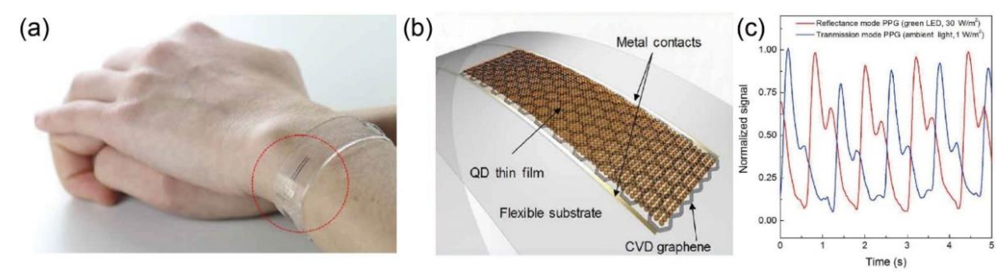
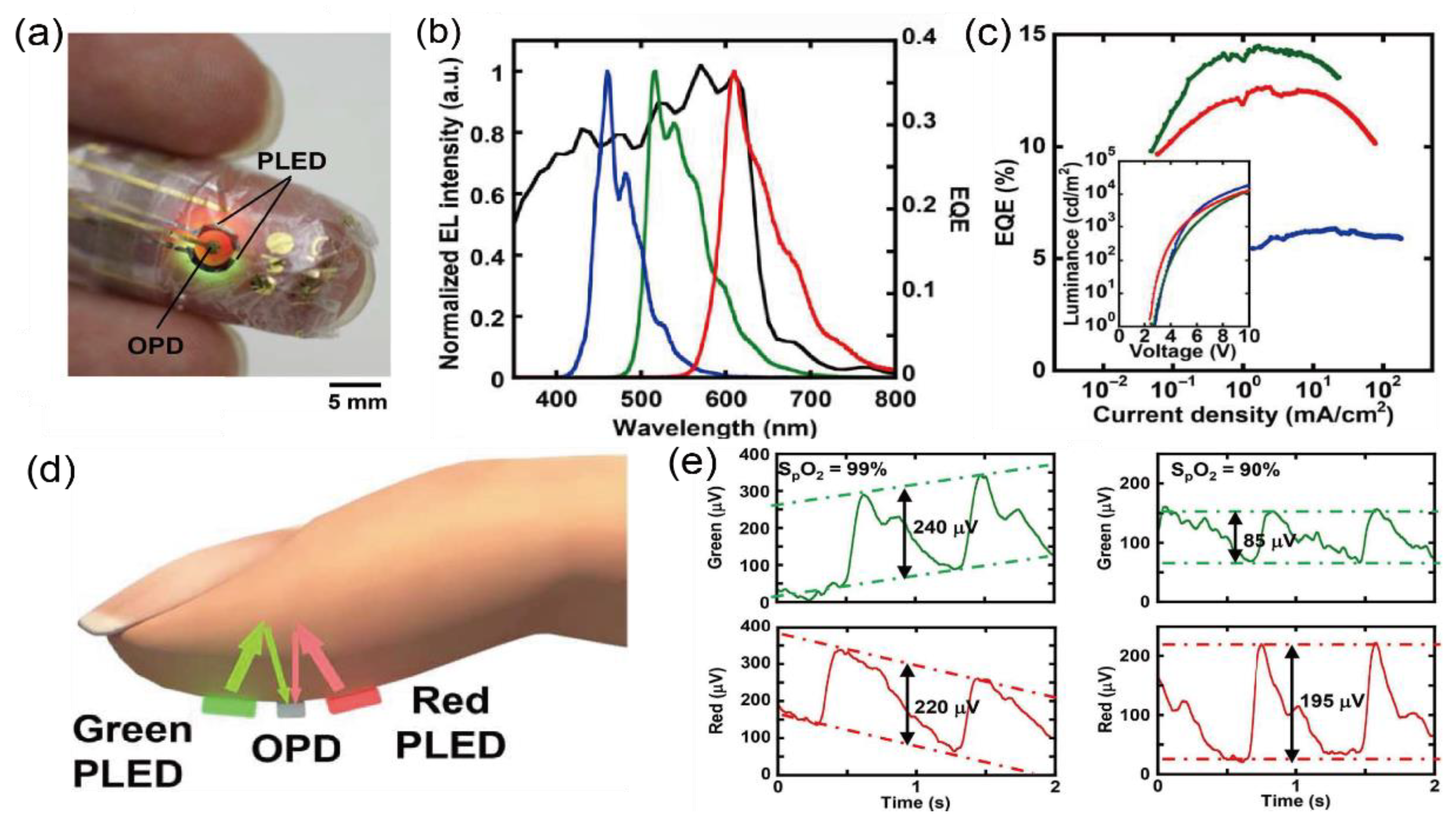
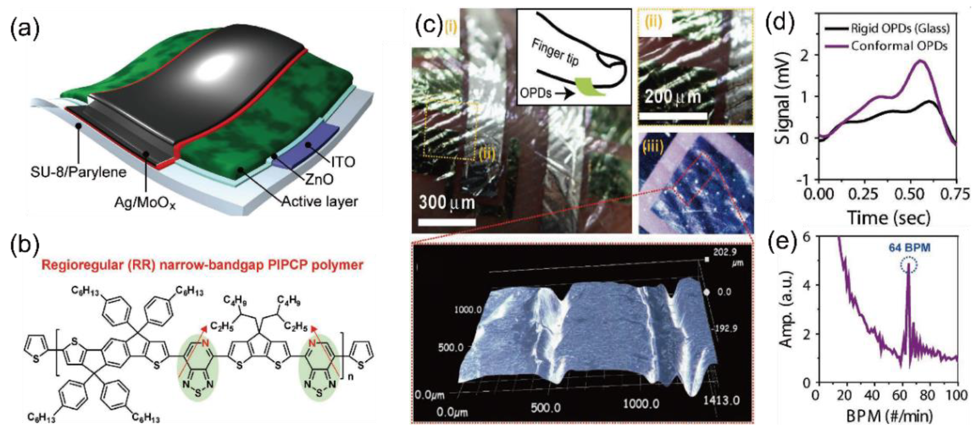
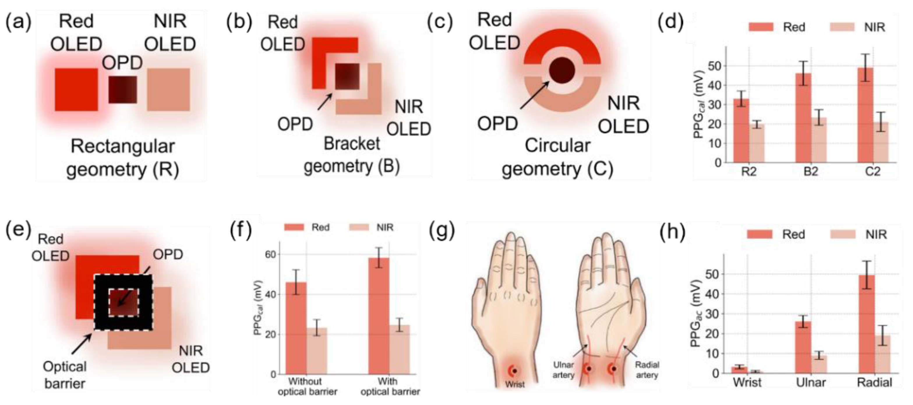
| Author | Year | Active Material | Bending Radius (mm) | Oximetry Mode | Photo-Responsive Range (nm) | Ref |
|---|---|---|---|---|---|---|
| Kim et al. | 2016 | Silicon PIN | - | Reflection | 350–1120 | [30] |
| Kim et al. | 2017 | Silicon PIN | 5 | Reflection | 350–1120 | [31] |
| Li et al. | 2017 | Silicon | - | Reflection | 450–1000 | [32] |
| Kim et al. | 2017 | GaAs | 2.4 | Reflection | 300–900 | [33] |
| Kim et al. | 2017 | PbS QD | 0.035 | Transmission | 400–1100 | [34] |
| Polat et al. | 2019 | Graphene/PbS QD | 16 | Reflection | 300–2000 | [35] |
| Yokota et al. | 2016 | P3HT:PCBM | 0.1> | Reflection | 350–800 | [36] |
| Park et al. | 2018 | PIPCP:PC61BM | 0.003> | Transmission | 300–900 | [37] |
| Khan et al. | 2018 | TMB:BB/PC71BM | >100 | Reflection | 400–950 | [38] |
| Khan et al. | 2019 | - | >50 | Reflection | 400–930 | [39] |
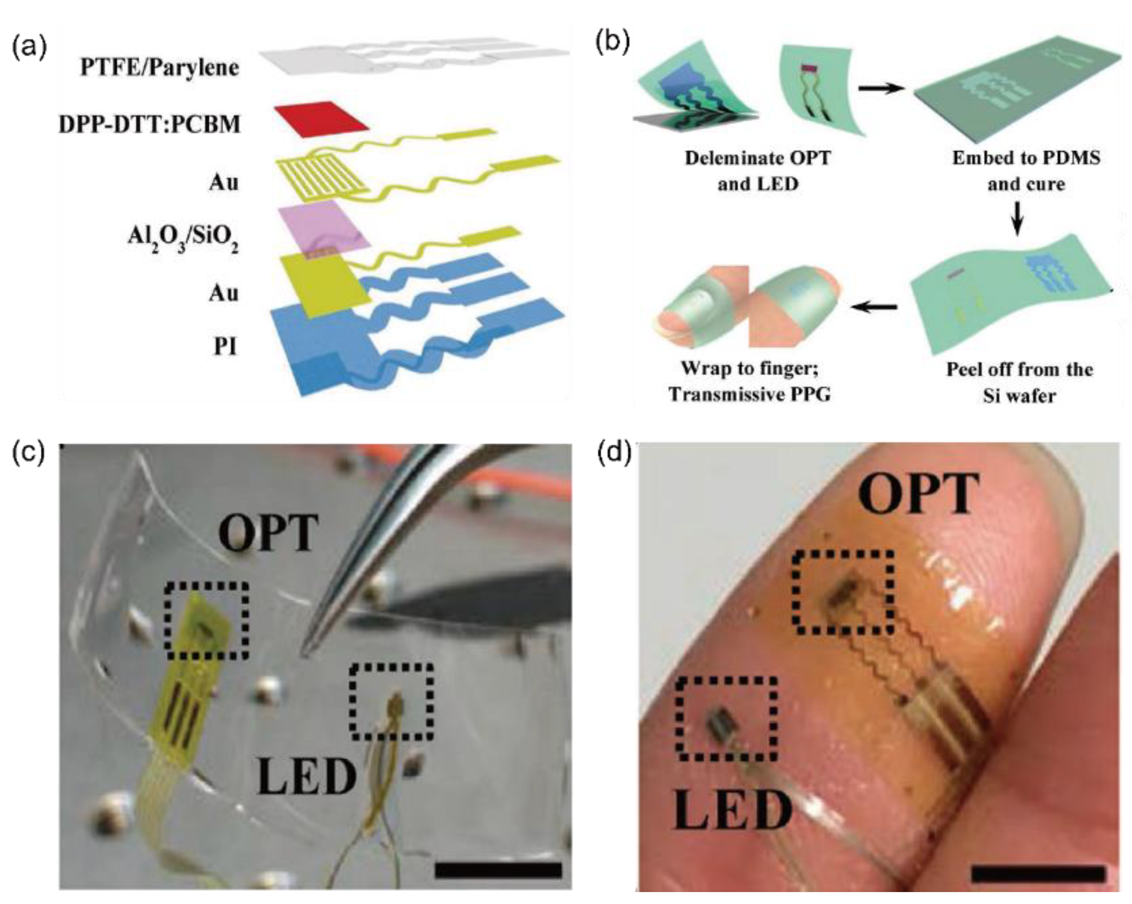
| Xu et al. | 2017 | DPP-DTT:PCBM | 9> | Reflection | - | [40] |
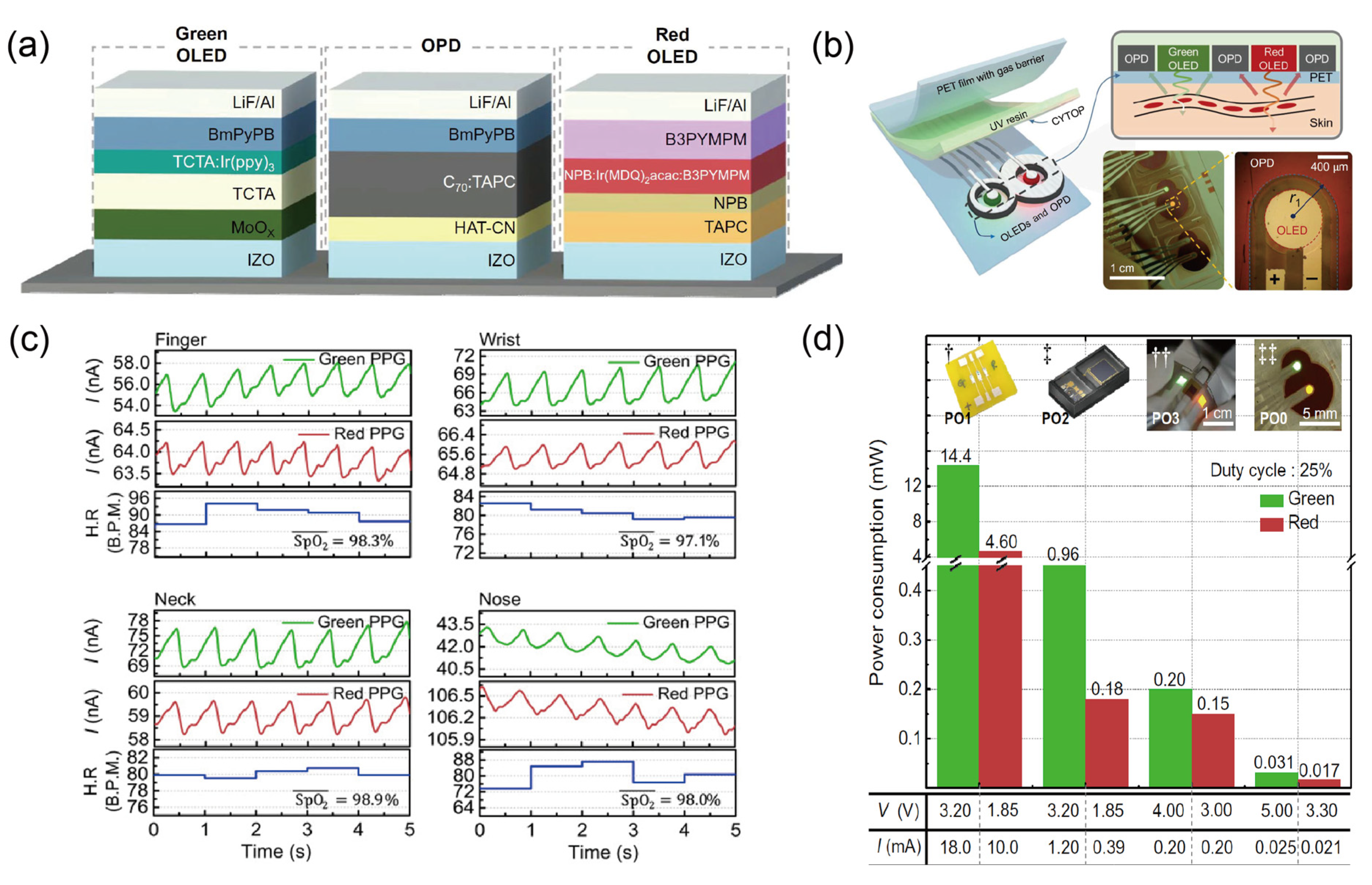
| Lee et al. | 2018 | C70:TAPC | 4.5 | Reflection | 350–750 | [41] |
| Kim et al. | 2020 | PTB7-Th:PC71BM | 3.5 | Transmission Reflection | 400–800 | [42] |
Publisher’s Note: MDPI stays neutral with regard to jurisdictional claims in published maps and institutional affiliations. |
© 2021 by the authors. Licensee MDPI, Basel, Switzerland. This article is an open access article distributed under the terms and conditions of the Creative Commons Attribution (CC BY) license (http://creativecommons.org/licenses/by/4.0/).
Share and Cite
Lee, I.; Park, N.; Lee, H.; Hwang, C.; Kim, J.H.; Park, S. Systematic Review on Human Skin-Compatible Wearable Photoplethysmography Sensors. Appl. Sci. 2021, 11, 2313. https://doi.org/10.3390/app11052313
Lee I, Park N, Lee H, Hwang C, Kim JH, Park S. Systematic Review on Human Skin-Compatible Wearable Photoplethysmography Sensors. Applied Sciences. 2021; 11(5):2313. https://doi.org/10.3390/app11052313
Chicago/Turabian StyleLee, Inho, Nakkyun Park, Hanbee Lee, Chuljin Hwang, Joo Hee Kim, and Sungjun Park. 2021. "Systematic Review on Human Skin-Compatible Wearable Photoplethysmography Sensors" Applied Sciences 11, no. 5: 2313. https://doi.org/10.3390/app11052313