The current WCLL BB layout is the result of a long and intense research design activity. During the 7 years of FP8 activities, several studies were conducted in order to investigate and evaluate the performance of different design variants and options. A set of neutronic, thermal-hydraulic, MHD, and thermo-mechanic analyses were therefore performed in order to justify the current WCLL BB architecture.
3.1. Neutronic Performance
In order to assess the neutronic performance of the WCLL BB, three-dimensional coupled neutron and gamma transport simulations have been performed [
16] by means of the MCNP5v1.6 Monte Carlo code and the Joint Evaluated Fusion File JEFF 3.3 nuclear data libraries, according to guidelines on neutronic studies. The analyses, carried out while adopting a fully heterogeneous model of the DEMO WCLL BB, mainly concerned the assessment of the TBR and shielding performance. According to the latest recommendations, the total TBR should be at least 1.15 [
23]. This design target was set to guarantee the necessary tritium generation to sustain a reactor while considering the impact of the in-vessel components that reduce its generation (e.g., penetrations for diagnostic or plasma heating systems) and losses due to the radioactive decay of tritium, as well to provide the start-up inventory for a follow-up D-T power plant. On the other hand, the blanket should ensure that the damage on VV steel, accumulated over the lifetime of DEMO (equivalent to 6 FPY), is below 2.75 dpa. Furthermore, the He concentration should be below 1 appm in re-weldable zones. The protection of the superconductive TFC is one of the most critical issues in the design of the BB: an evaluation of the fast neutron flux on the superconductor coils (design target: <10
9 n/cm
2/s) and the estimation of the nuclear heating due to neutrons and gammas deposited on the winding pack (design target: <5 × 10
−5 W/cm
3) can provide a reliable verification of the WCLL BB’s shielding efficiency [
24].
The MCNP DEMO model integrating the WCLL blanket was used to assess the nuclear performance of the WCLL DEMO BB, and results were normalized to 1998 MW fusion power (neutron yield: 7.095 × 10²⁰ n/s). The poloidal distribution of the neutron wall loading (NWL) was estimated for the inboard and outboard segments; maximum values were reached in the outboard and inboard equatorial zones (1.33 and 1.1 MW/m2, respectively), while the poloidal average was 0.93 MW/m2.
The verification of the tritium self-sufficiency for the WCLL DEMO reactor was carried out through the assessment of the total TBR by means of track-length (F4 tally) with proper tally multipliers (FM card) for each component of the BB that contributes to tritium generation while considering both neutron capture reactions on 6Li and 7Li isotopes. The resulting total TBR for this configuration was found to be 1.15, so the design target for tritium self-sufficiency was satisfied: 69.7% of the tritium was produced in the outboard sector, while 30.3% was generated in the inboard.
A breakdown of the nuclear power deposition due to neutrons and secondary gammas in the WCLL blanket components is provided in
Table 1. The total nuclear power deposited in the BB system was 1716 MW: in particular, about 78.2% was found to be deposited in the BZ, manifolds, BSS, and caps; about 18% was deposited in the FW and side-walls; and about 3.8% was deposited in the W armour. Moreover, most of the power (70.3%) was deposited in the outboard region. Finally, it has to be considered that this nuclear heating value had to be normalized to the required TBR (TBR
req), which is presently equal to 1.05 [
23]. Indeed, since the current neutronic model does not consider penetrations due to auxiliary systems, the tentative requirement for the TBR design target (TBR
tar) was increased up to 1.15, where it stands currently [
23]. Considering these assumptions, the effective nuclear heating value deposited within the BB was found to be equal to 1566.12 MW (1716 MW * TBR
req/TBR
des). Obviously this evaluation needs to be assessed in detail in future neutronic analyses that adopt a detailed model of the in-vessel components (BB, divertor, and auxiliaries).
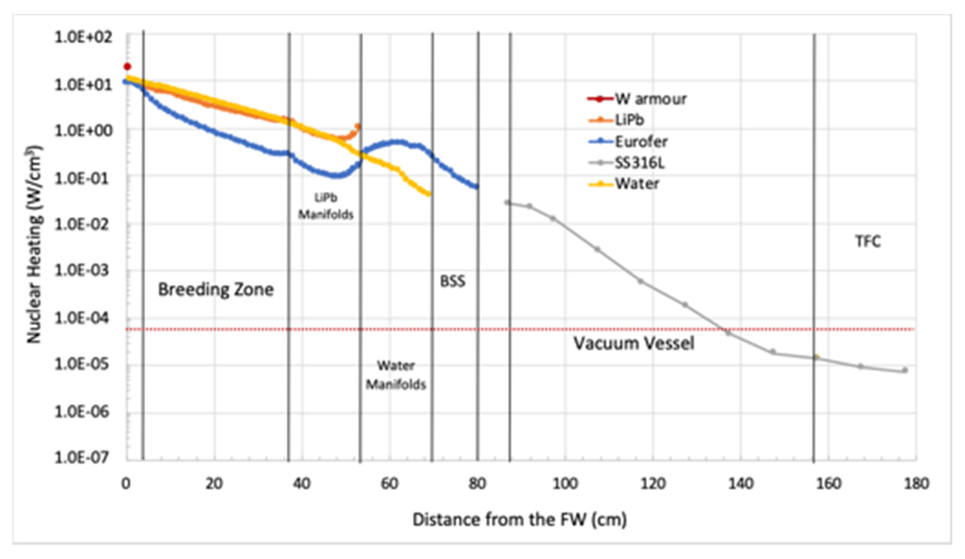
As an example, the radial distribution of a nuclear heating density radial distribution for the inboard region is depicted in
Figure 5. The dotted horizontal line highlights that the limit on the TFC nuclear heating (5 × 10
−5 W/cm
3) was fulfilled.
The total neutron flux values at the inboard and outboard W armour were found to be 6.1 × 10¹⁴ and 5.5 × 10¹⁴ n/cm2/s, respectively. In the inboard section, the blanket/manifold system was found to provide an attenuation of more than two orders of magnitudes to the VV inner shell and neutron flux further decreases of three orders of magnitude across the VV: 5.1 × 10⁸ n/cm2/s (total) and 1.55 × 10⁸ n/cm2/s (fast) on the TFC, respectively. Thus, the WCLL BB’s shielding capability ensures that the 109 n/cm2/s design limit for the fast neutron flux on the TFC is fully satisfied. The evaluation of the damage on the VV stainless steel provided a value of 8.7 × 10⁻³ dpa/FPY for the inboard segment and 2.46 × 10⁻³ dpa/FPY for the outboard one, so the shielding capabilities of the breeding blanket and manifold structures are sufficient to guarantee the integrity of the VV over the 6 FPY DEMO lifetime (0.052 and 0.015 dpa for the inboard and outboard VV inner shells, respectively). Regarding helium production, the maximum cumulated He production, assessed through over the entire 6 FPY lifetime, was 0.4 appm and 0.15 appm for the inboard and for the outboard, respectively—in both cases, the limit of 1 appm was fulfilled.
3.2. Thermal-Hydraulic Performance
Several campaigns of thermal-hydraulic calculations were carried out over the years to support WCLL BB design activities, confirming good performance or suggesting revisions of the investigated layout. The following section reports results from steady-state and transient analyses performed on elementary cells placed in the equatorial mid-plane of the COB segment, as well as steady-state analyses of the water manifolds.
3.2.1. Steady-State Analysis of the Elementary Cell
The set-up of the consolidated geometry for the WCLL BB elementary cell is the outcome of several studies aimed at the continuous improvement of its global performance [
10,
11,
12,
13,
25]. Focussing on the thermal point of view, several configurations differing in the number and layout of DWTs, as well as in the number of the FW channels, have been assessed in the last few years. Moreover, the influence of the adoption of different correlations for thermo-physical properties on the thermal performance of the elementary cell design has been deeply investigated [
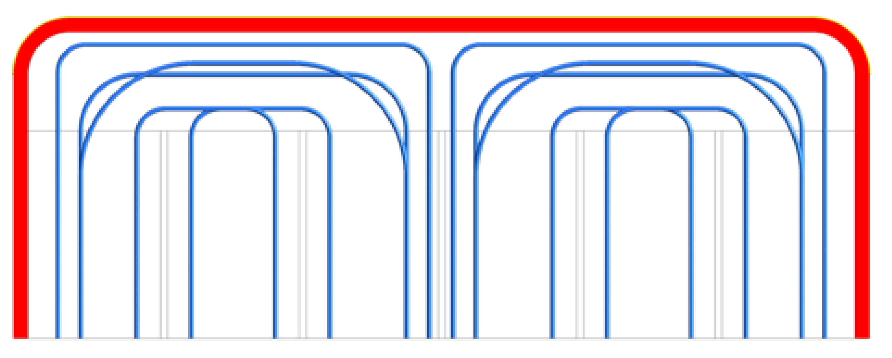
25]. The outcome of these studies has been the set-up of the WCLL2018.v0.6B configuration, currently adopted as the reference one (
Figure 6). The loads and boundary conditions adopted for the different analyses are summarized as follows:
FW heat flux equal to 0.32 MW/m2 linearly decreasing down to zero on the SWs.
Radial distribution of volumetric nuclear heat power imposed to EUROFER and PbLi domains to take the heat power deposited by neutrons and γ rays into account [
16].
Periodic boundary conditions in the poloidal direction to reproduce the presence of adjacent breeding units.
FW and DWT water inlet temperature equal to 295 °C.
Adiabatic condition for the BP.
Mass flow rate and static pressure are imposed to fluid domains at inlet and outlet sections, respectively.
No-slip condition at the interface between coolant and steel walls.
No buoyancy effects are considered in the PbLi model.
Reynolds Averaged Navier–Stokes equations are used in the fluid domains and the wo-equations k-ω shear stress transport (SST) model is exploited to simulate turbulence effects.
Figure 6.
WCLL2018.v0.6B tube layout.
Figure 6.
WCLL2018.v0.6B tube layout.
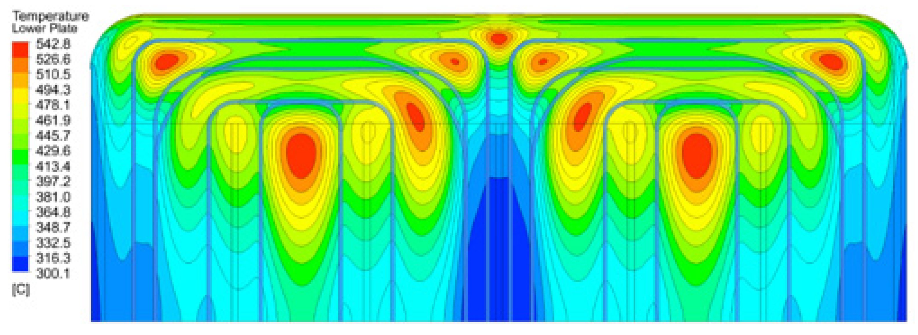
Results obtained from CFD analysis performed on the WCLL2018.v0.6B model predicted an acceptable EUROFER temperature field. In fact, the maximum temperature of 542.8 °C was predicted to be reached in the lower and upper stiffening plates, as shown in
Figure 7. The only region where the temperature of 550 °C was found to be overcome is the baffle plate domain, where the maximum temperature was predicted to slightly exceed the limit, being equal to 552 °C. However, since this component has no structural functions, this slight overrun is considered to be acceptable.
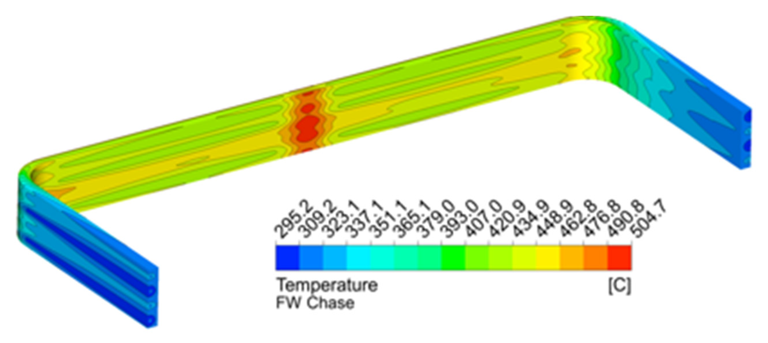
Concerning the FW–SW complex, the maximum temperature was foreseen to be 504.7 °C (
Figure 8), reached in proximity of the toroidal symmetry plane because this area experiences high nuclear power density and the highest distance from the DWTs. Regarding the coolant outlet temperature, calculations confirmed that the average outlet temperature of both FW and BZ water systems was 328 °C. The adoption of the recirculation in the BZ system, resulting in an increase of the average water velocity, strongly supports a decrease of the temperature values and avoids the arising of a thermal crisis, as well as contributing to the returning of a homogeneous average outlet temperature.
3.2.2. Transient Analysis of the Elementary Cell
Transient thermal analyses were focussed on the investigation of the response of the COB equatorial elementary cell when subjected to non-steady-state load scenarios typical of the DEMO machine. In particular, both the ramp-up phase (where the reactor passes from the dwell phase up to the full power operating one) and the ramp down phase (where the reactor passes from full power to dwell state) were assessed.
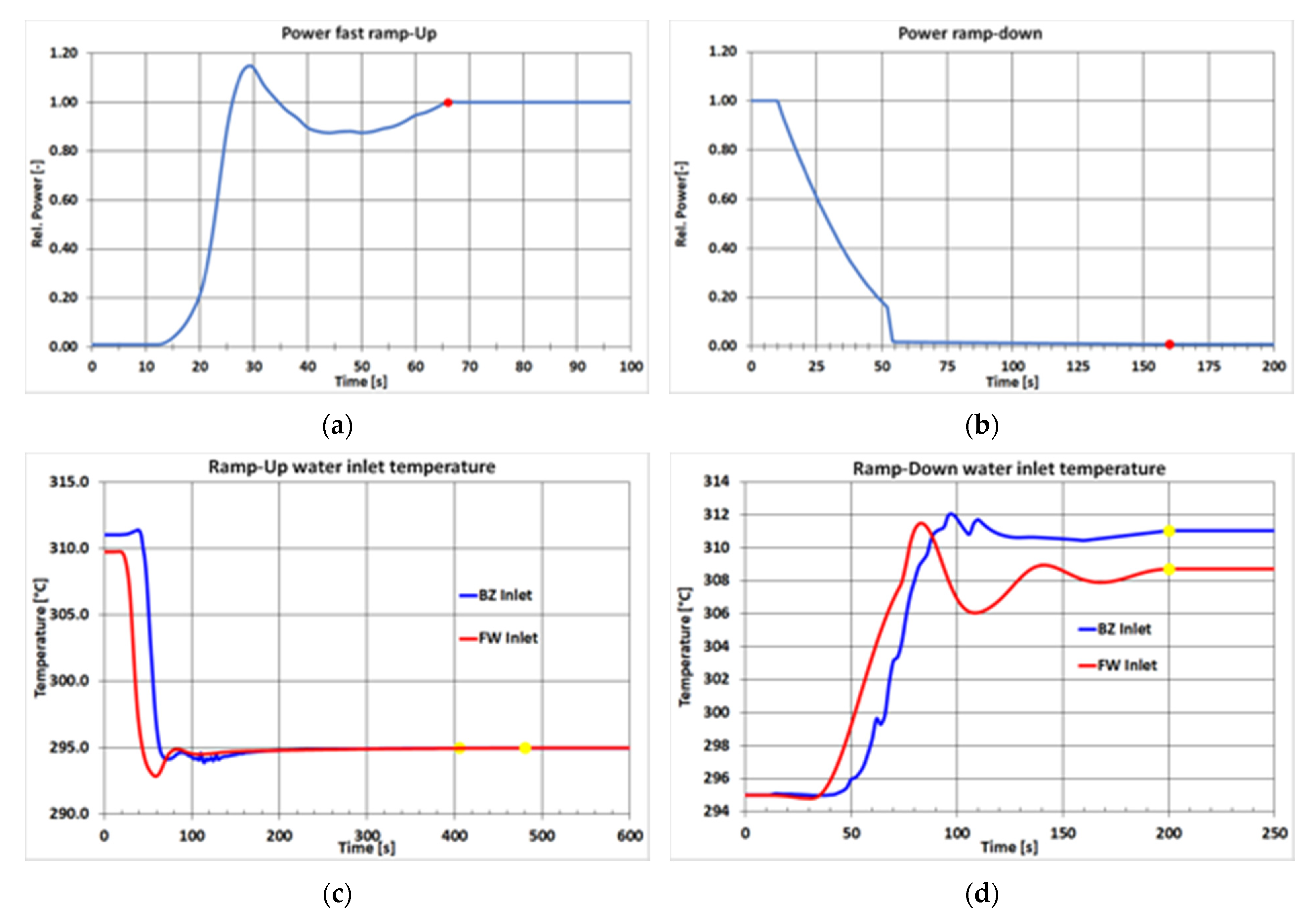
The same type of loads and boundary conditions adopted for steady-state analyses already reported in the previous sub-section were adopted for transient calculations. The only difference was represented by the heat power and water inlet temperature values. Their behaviours during the ramp-up and ramp down phases are plotted in
Figure 9. The time–behaviour relationship of both nuclear heating and heat flux from plasma was derived from plasma behaviour reported in [
26], while the temperature trends were derived from analyses performed on a global model of the reactor adopting the RELAP5/Mod3.3 system code [
27].
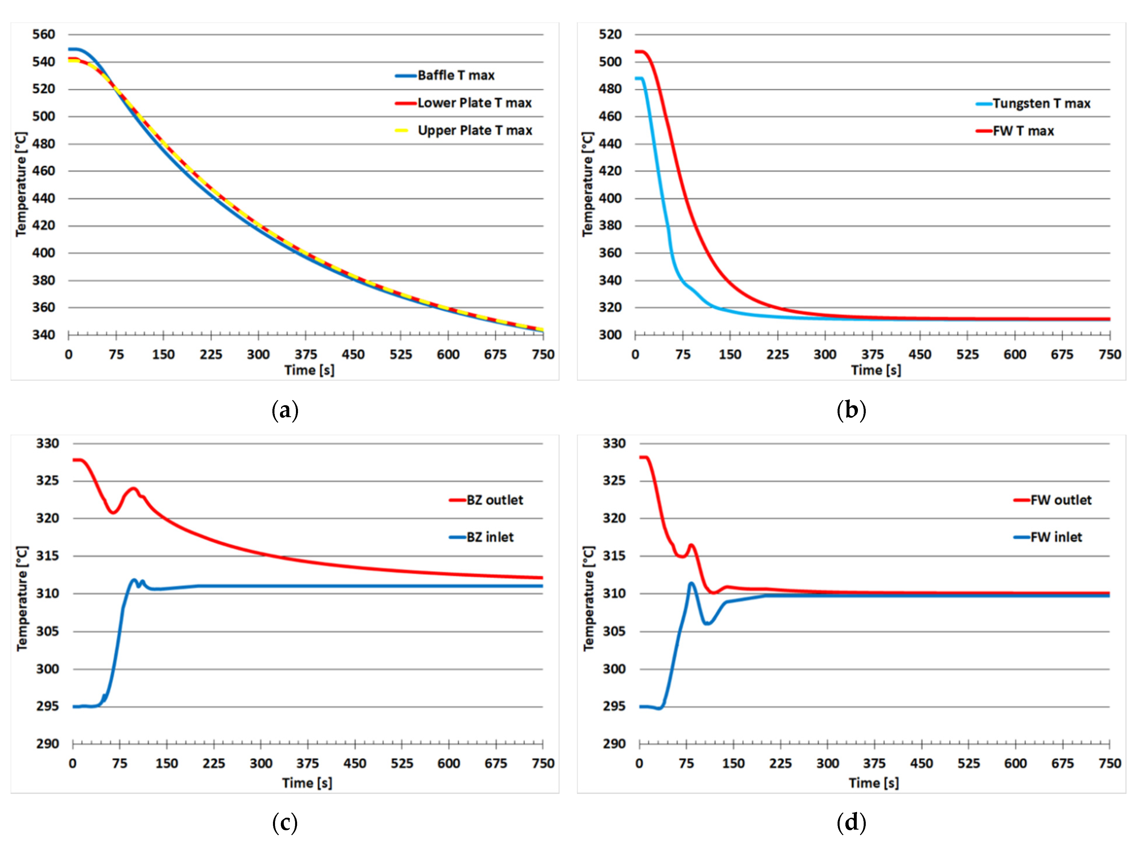
A transient analysis with a duration of 1000 s was carried out to investigate the dwell–pulse transition. The main aims of this calculation were to assess the thermal performance of the EUROFER structures in the first phases of this transient scenario, in which an “over-power” condition of about 15% of the nominal one was predicted (
Figure 9a), as well as to study the behaviour of both inlet and outlet coolant temperature trends. The obtained results were comparable to those obtained from steady-state analysis reported in the previous section. The maximum temperature of EUROFER structures remained below the maximum suggested value of 550 °C for the whole duration of the transient analysis, as reported in
Figure 10a,b. In this figure, it can be seen that both BZ and FW EUROFER structures experienced a noticeable thermal drop of about 200 °C in the first 150 s, while the steady-state conditions were reached after about 300 s. Concerning the PbLi, its maximum temperature presented a trend very similar to that of the stiffening plates.
The behaviour of inlet and outlet water coolant temperatures during the ramp-up transient analysis is reported in
Figure 10c,d. For both the FW and BZ coolant systems, the inlet temperatures reached their steady-state values after about 100 s from the beginning of the ramp-up. On the contrary, the BZ and FW outlet water temperatures showed different behaviours. The first, after a peak at about 100 s, very smoothly increased up to its reference value of 328 °C in about 800 s. The FW ones, instead, had much more dynamic behaviour, reaching their steady-state conditions in about 300 s. The pronounced delay in BZ water temperature increase was closely related to the PbLi timing, as the BZ DWTs were immersed in the breeder. The PbLi thermal inertia deeply affected this system, greatly delaying the achievement of stationary conditions.
The second transient analysis concerned the pulse–dwell phase or ramp-down scenario (
Figure 9b). The main goals of this analysis were to evaluate the maximum EUROFER temperature trend in order to verify that the elementary cell returned to an isothermal dwell condition in the expected 650 s and to verify that the BZ and FW water outlet temperatures met the primary heat transfer system (PHTS) requirements.
The total time of the simulation was set to 760 s to consider 10 s of the pulsed phase and guarantee an additional 100 s at the end of the dwell in order to evaluate if and when the system returned to stationary conditions before a new cycle began.
The thermal-hydraulic analysis demonstrated that the BZ system of the elementary cell did not reach a steady-state condition at the end of the transient analysis. In particular, the BZ returned a maximum temperature with a parabolic decreasing trend in both EUROFER structures and PbLi, as shown in
Figure 11a. Thus, even though an additional 100 s were considered, it seems that the BZ system did not reach “dwell steady-state” conditions between two consecutive plasma pulses. It could be worth investigating whether temperature build-up phenomena can arise in the BZ, mainly due to the huge thermal inertia of the PbLi. On the other hand, the FW system showed completely different behaviour (
Figure 11b), providing a faster response and reaching steady-state conditions after about 300 s from the beginning of the calculation. Concerning cooling water, the temperature of inlet water reached steady-state conditions after about 200 s from the beginning of the transient analysis. Concerning the outlet water temperatures, BZ and FW coolants experienced the different behaviours already seen for the EUROFER structures. Indeed, the FW outlet coolant reaches a steady-state condition after about 300 s while the outlet temperature of BZ coolant at the end of calculation continued to decrease. The coolant behaviour is reported in detail for both BZ and FW systems in
Figure 11c,d.
These analyses demonstrated that the COB equatorial cell was able to effectively withstand the thermal loads associated with the DEMO ramp-up and ramp-down transient periods.
3.2.3. Steady-State Analyses of the Manifolds
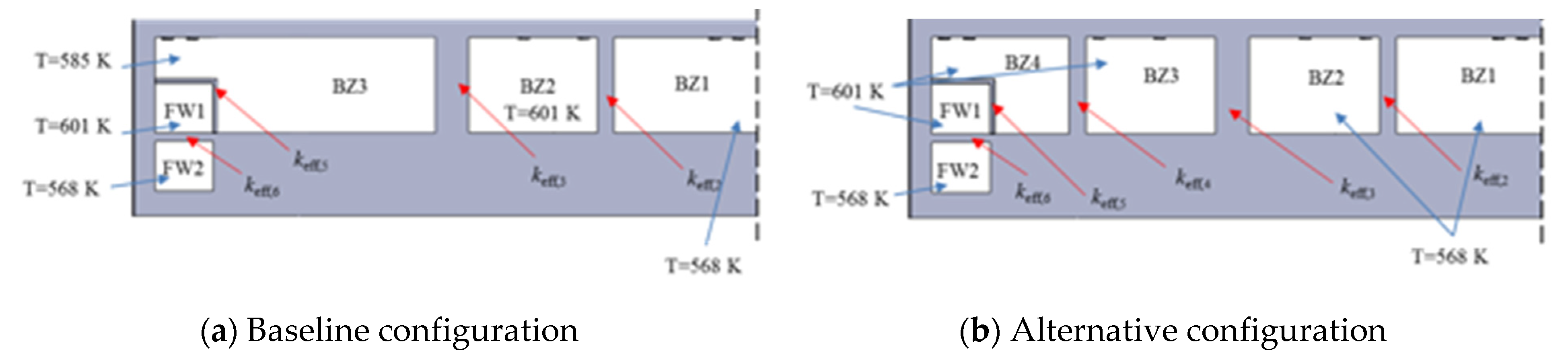
In order to assess the heat transfer phenomena between inlet and outlet water manifolds in the BSS, a parametric analysis was conducted for the first manifold layout. Indeed, such effect must be minimized to avoid the reduction of both the plant efficiency and cooling capacity of the system. Though a previous design of the manifold was analysed, the conclusions of this study are still valid for the updated manifold design, as the layout of the different manifold chambers has not significantly changed. In this study [
28], two different geometries of the BSS and manifold locations were considered (
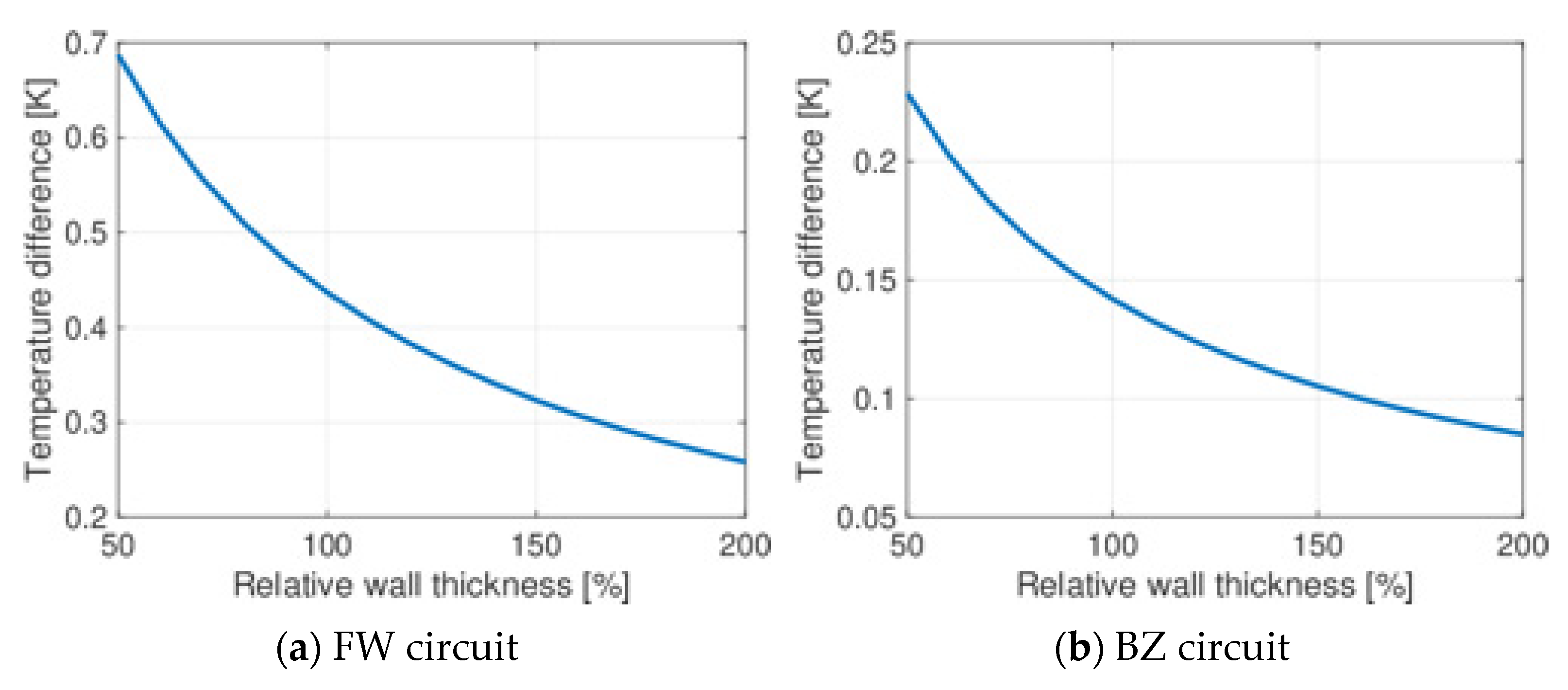
Figure 12), accounting for two possible coolant flow paths in the BZ—one foreseeing the recirculation (baseline) and one not (alternative). Then, for both geometries, the thickness of the walls separating the different manifolds was varied, and the heat transfer was computed using the GETTHEM 1D thermal-hydraulic model. In order to derive correlations between the thermal resistance and wall thickness, a set of 2D FEM analyses was run using the FreeFem++ software. The presence of the PbLi manifold and the radiation towards the VV (supposed to be at the uniform temperature of 40 °C) were considered as well. The obtained results showed that the walls provided sufficient thermal insulation between the different manifolds in all the considered configurations—both in the baseline and alternative geometries. The parametric campaign on the manifold thicknesses highlighted that the heat transfer among the different manifold channels could be considered negligible: in fact, the reduction of the coolant temperature at the BB outlet was well below 1 °C (which was comparable with an estimated 3% accuracy of the GETTHEM models [
29]) and, as such, would not significantly affect plant efficiency; this effect was stronger in the BZ loop due to the larger mass flow rate in the BZ manifolds (
Figure 13). As previously mentioned, the WCLL BB manifold systems were partially re-designed in 2019, with both the coolant and PbLi paths modified. Nevertheless, most of the outcomes obtained from the previous manifold layout remain valid for the new configuration.
A study concerning the current manifold layout was conducted with the goal of assessing its hydraulic performance. The study [
30] was conducted on the water manifold of the COB segment using the commercial tool STAR-CCM+, version 15.02.009, and adopting the following modelling assumptions:
DWTs were lumped in two equivalent pipes, with a fictitious porous medium filling the pipes, suitably calibrated to lump the hydraulic behaviour of the DWT strings.
Taking advantage of the symmetry of the structure, only half of the total geometry as modelled.
Only the fluid domain was addressed.
Since the spinal manifolds have the only function of driving the coolant from the inlet pipe to the bottom of the segment and from the top of the segment, they were not modelled.
Looking at the selected computational domain, it could be identified a peculiarity of the manifolds: the variation of the cross-section available for the fluid along the curvilinear coordinate. Following the fluid flow from the bottom to the top of the segment, the cross-section available for the flow tended to decrease along the inlet manifold (IM) while increasing for the outlet manifold (OM). This was fully in line with the fact that while moving upward, part of the coolant passes from the IM to the OM. The two recirculating manifolds (REC1 and REC2) showed different behaviours: the cross-section of REC1 was constant all along the manifold, since it just acted as a fluid buffer. The cross-section of REC2 was kept constant up to the point, under the inlet/outlet piping in the outboard manifold, where it underwent an abrupt contraction that we expect could somehow affect the flow field. A polyhedral mesh, providing grid-independent results, was tailored for the hydraulic analysis, resulting in 68 MCells.
Steady-state calculations were carried out by adopting a segregated solver with the k-ω SST turbulence model and adopting a uniform temperature of 313 °C.
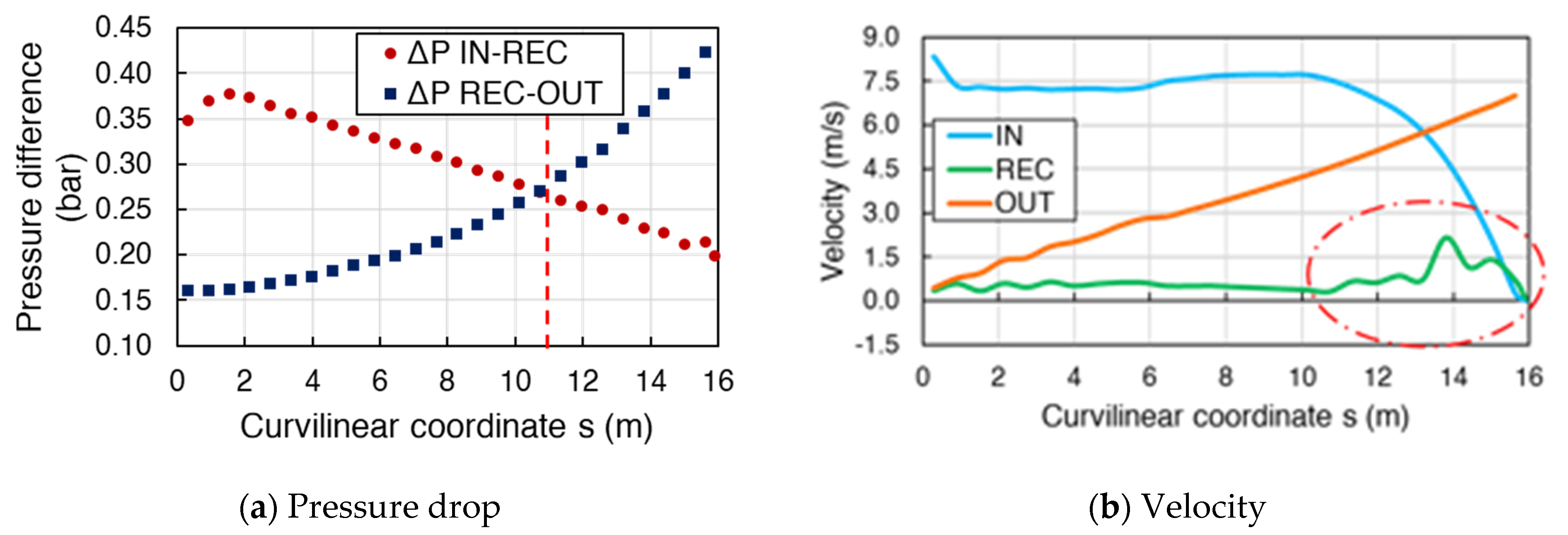
The calculated pressure maps at different representative poloidal sections showed a quite uniform distribution, a posteriori confirming that a simplified model calibrated on a single elementary cell, which neglects any possible perturbation of the neighbouring cells, is suitable for simulation. From the average values of the manifold pressure at the same curvilinear location, the overview of the pressure as a function of the coordinate along the segment could be derived. The IM pressure was found to decrease along the fluid path, as expected by the fact that an upward flow was forced in the manifold. The pressure decrease in the IM drove the pressure decrease in the REC and in the OM, although to different extents (note that the pressure measurements in the sections of the two manifolds, REC1 and REC2, were averaged to a single value). Plots of the pressure drop between IN and REC and between REC and OM are reported in
Figure 14a; these are interesting since they represent the driver for the variation of the BU mass flow rate along the segment. Moreover, the vertical dashed lines indicate for the location of the sudden contraction in the cross-section of the recirculation manifold.
The behaviour of the coolant speed, averaged on the different manifold cross-sections, is reported in
Figure 14b as a function of the curvilinear coordinate. The average velocity in the IM did not remain constant, potentially due to the reduction of the manifold flow area, but was significantly reduced in the upper part of the segment. The average speed in the OM monotonically increased from the bottom to the top. However, in the REC manifolds (with the exception of the upper part of the manifold, where a sudden reduction of the flow section was faced due to some oscillatory behaviour) a very small net velocity was computed. When the net longitudinal speed was converted into a net mass flow rate, it was found that it monotonically decreased in the IM and monotonically increased in the OM. Meanwhile, a small net flow rate was computed in the REC, though only before the flow area reduction.
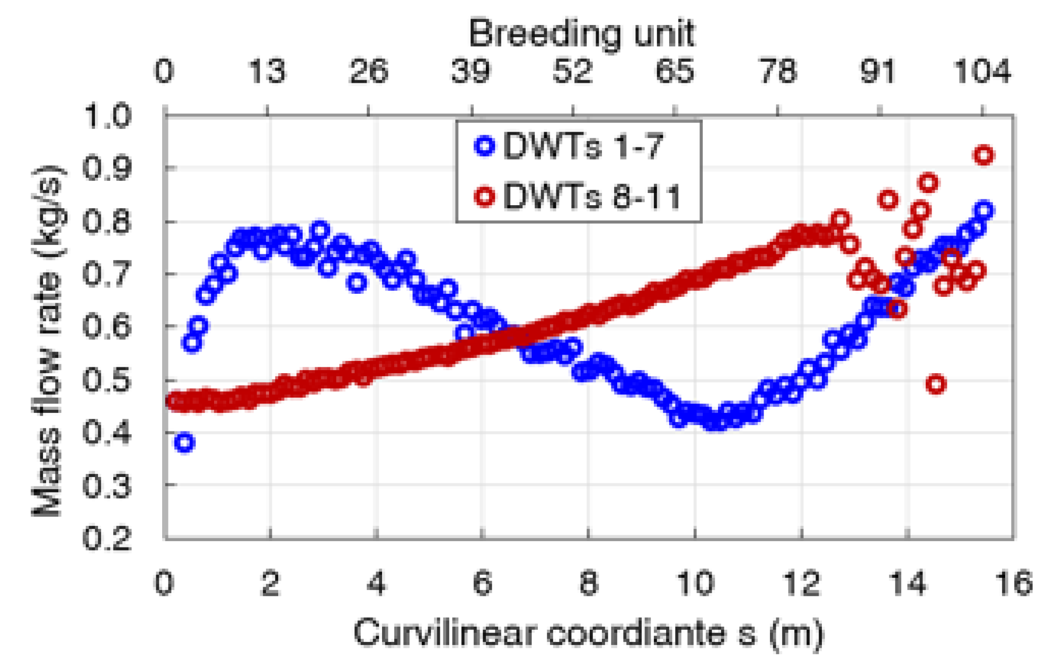
Concerning the different cells, the mass flow rates in the two different equivalent porous pipes (the first mimicking DWTs 1–7 from IM to REC1, the second mimicking DWTs 8–11 from REC2 to OM) are reported in
Figure 15. In the pipes mimicking DWTs 1–7, the mass flow rate was found to have a non-monotonic behaviour from bottom to top. In more detail, in the bottom part the elementary cell flow rate increased as an effect of the increased pressure drop between the IM and the REC. In the mid part, it progressively decreased, again driven by the reduction of Δp between the IM and REC manifolds. At the same time, the mass flow rate in pipes mimicking DWTs 8–11 monotonically increased and balanced that of DWTs 1–7 around the equatorial plane of the manifold. From that point on, the flow from REC to OM overcame that from the IM, and in the top part of the segment, the suction effect became so strong that it drove an increase of the flow rate in DWTs 1–7. The suction effect was also helped by the reduction of the flow area in the REC, which helped to make it act just as a portion of pipe rather than a buffer for the coolant. For the top Bus, the mass flow rate in DWTs 8–11 showed oscillatory behaviour that could have been caused by local vorticity and needs to be further investigated. Finally, the computed results showed that the mass flow rate could vary up to a factor of 2 between cells located at different heights of the manifold. In particular, in the bottom part of the segment, the mass flow rate for DWTs 1–7 was, on average, larger than in the top part of the segment. The possible impact of such unbalance on heat removal capability needs to be assessed.
3.3. Magneto-Hydrodynamic (MHD) Performance
Concerning the WCLL BB magneto-hydrodynamic (MHD) performance, a series of local and global studies has been carried out. In particular, local MHD analyses were performed through direct numerical simulation with both ANSYS CFX and FLUENT. The system-level assessment of MHD pressure loss in the PbLi loop was carried out with a semi-analytical model that integrated theoretical relations and numerical results.
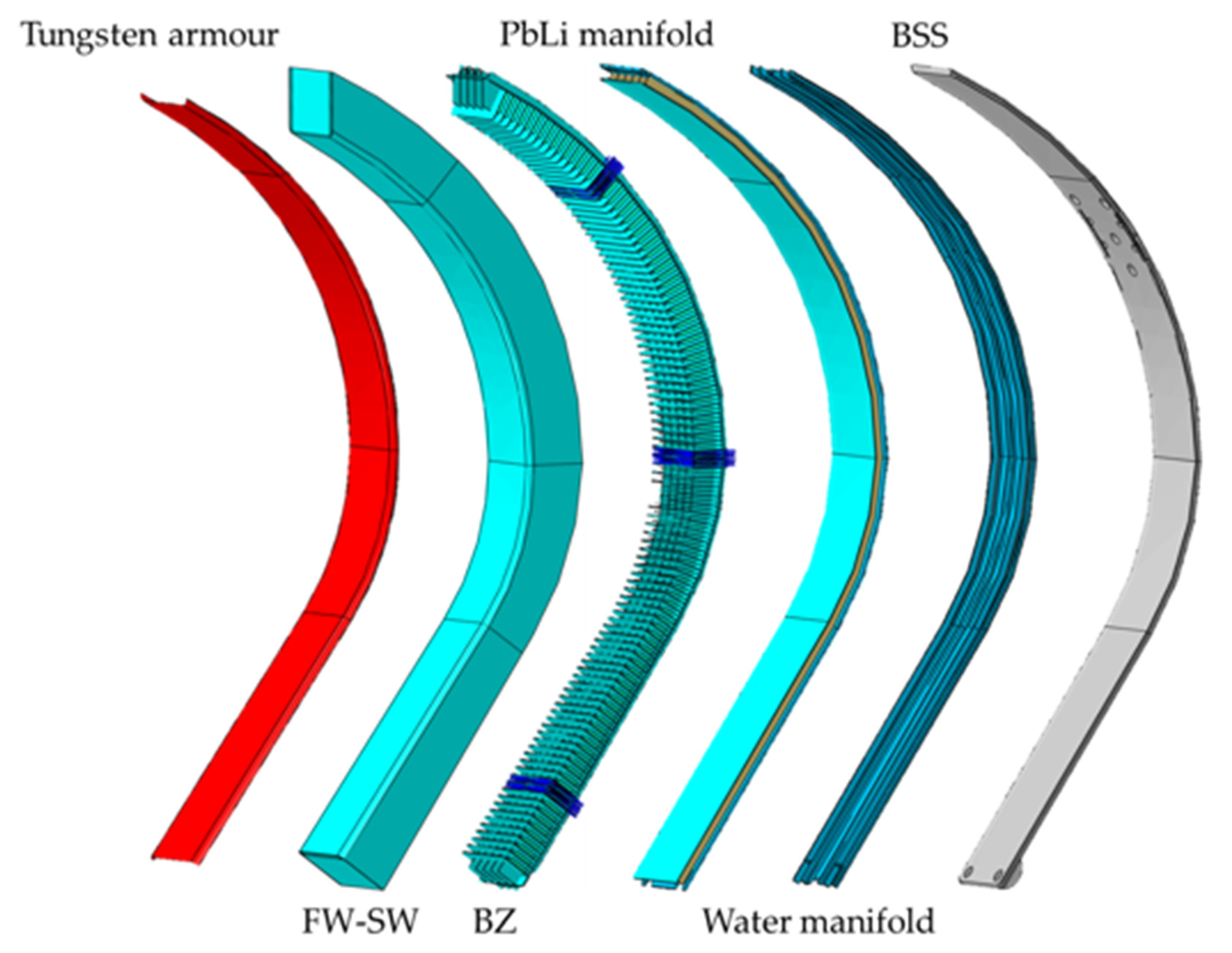
The simulations of the BZ considered two different regions of the design: the radial channels and the frontal PbLi region close to the FW. Geometrically, both regions were found to have very different degrees of complexity, mainly due to the density and shape of the water tubes (
Figure 3).
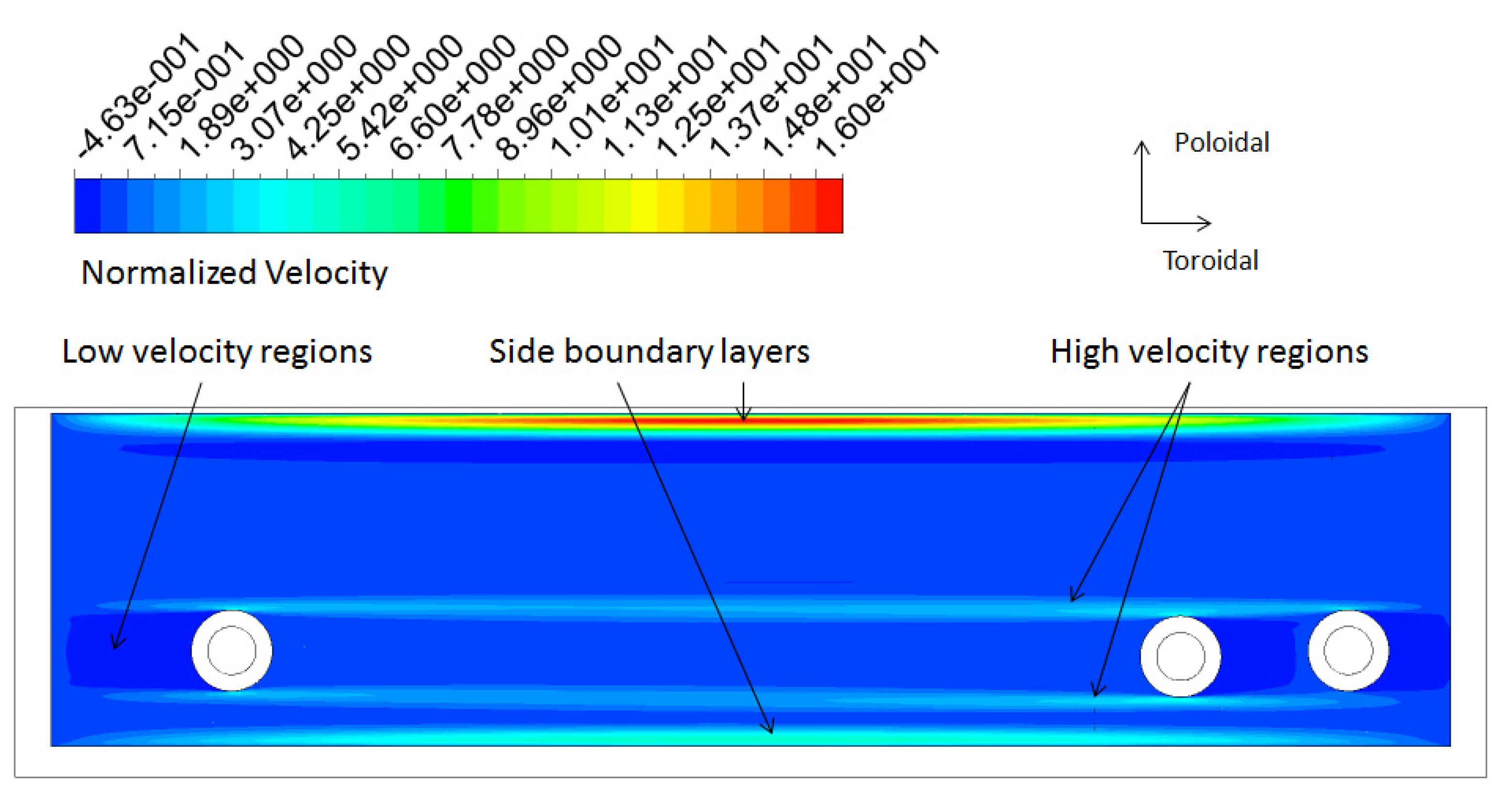
In order to simplify the analyses, these two regions were treated separately. The radial channels were first analysed using a fully developed model. This kind of models assumes that far enough from the 3D elements, the induced currents are cross-sectional (2D). The simulations enabled the computing of the influence of the conductor tubes on the steady-state PbLi velocity profile (
Figure 16). The presence of water tubes disturbed the induced current distribution, thus producing zones of different velocities in their vicinity.
Heat transfer computations in the radial channels were carried out afterwards using the 2D MHD velocity profile as an input. It was found that heat transfer by advection could be significant in these regions. Unfortunately, fully developed models do not allow one to compute buoyancy effects in radial channels. The maximum temperature at the PbLi/EUROFER interface was found to be 580 °C (
Figure 17), slightly above the temperature limit.
The second group of analyses were dedicated to the frontal region of the BZ, close to the FW [
31]. These needed to include buoyancy interactions since it is expected that they play a major role in this region. Therefore, 3D magneto-convection simulations were carried out. The system of study only included the FW region of one of the six parallel circuits of the BZ (the second or the fifth circuit). Additionally, in order to use a structured mesh (increasing the stability of the solution), the geometry as simplified. The tubes were assumed to be oriented along the toroidal direction, neglecting the 3D effect caused by the tube curvature. This simplification could have a significant impact in the region next to the radial channels, but it is not expected to significantly affect the regions closer to the FW, which were the main object of interest of the analyses (see tube layout in
Figure 6).
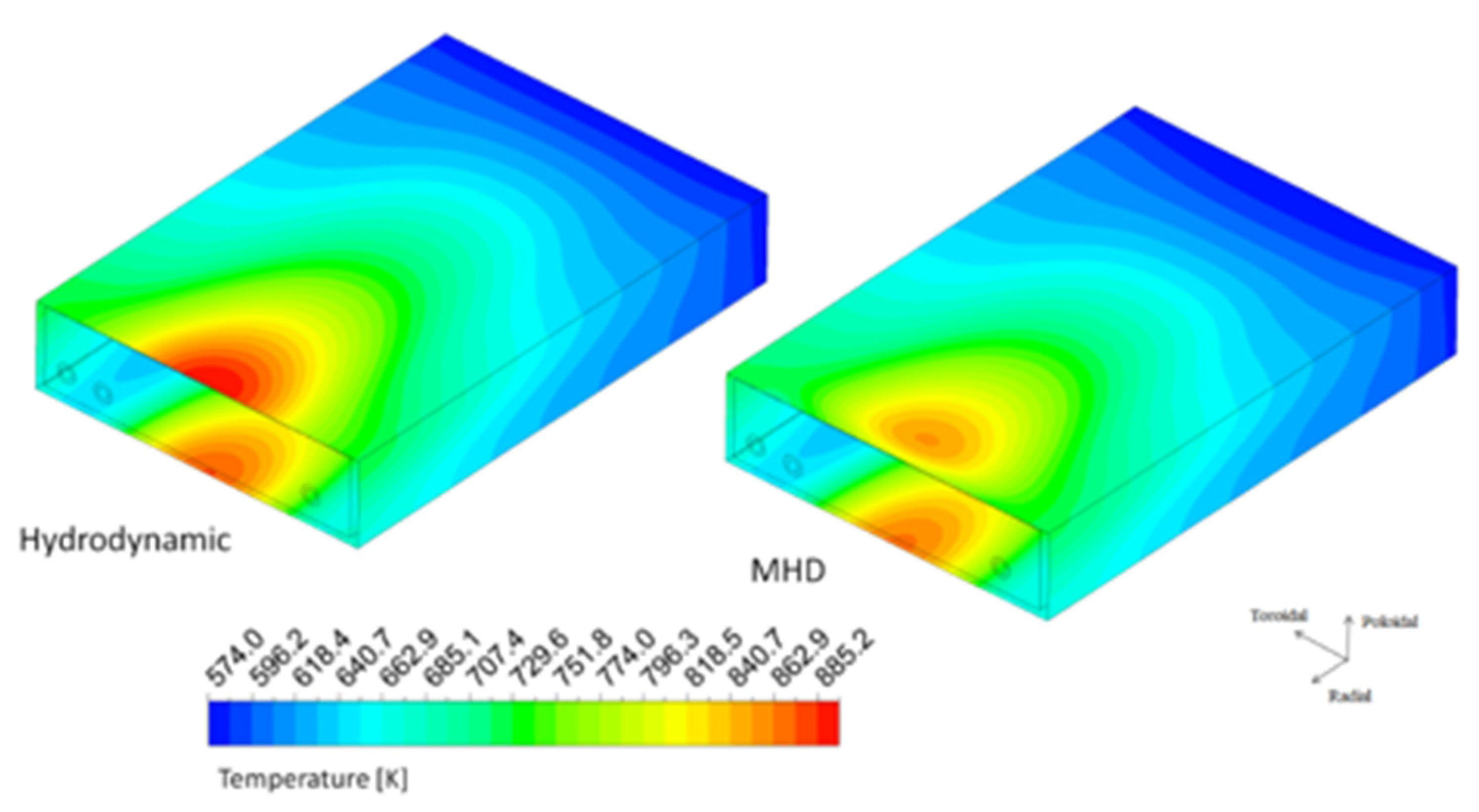
Figure 18 depicts the velocity stream lines and temperature contours in the central radial–poloidal plane obtained in the transient simulations after 200 s. The presented results correspond to a situation with a moderate Hartmann number (Ha = 1000). The gravity field was adjusted to maintain the actual ratio between buoyancy and Lorentz’s forces. This was done because it was found that, with the employed mesh, it was hard to preserve stability and charge conservation for Ha values higher than 3000.
According the obtained results, medium-size convective vortexes oriented with the magnetic field were formed next to each tube and next to the FW. The simulation confirmed that the PbLi almost exclusively moved via natural magneto-convection in most of the FW region. Indeed, no appreciable effects caused by the inlet velocity or temperature of the radial channels in most of the domain were found. The temperature distribution was very similar to the one obtained using a pure conductive model, and no hotspot above the EUROFER temperature limit was found. This implies that the heat transfer in the FW region is mostly driven by conduction and that the cooling system can effectively refrigerate the breeder. Moreover, there have been interesting studies comprising magneto-convective simulations of the WCLL breeder zone using COMSOL [
32]. Though the heat source used in these works was not the same that the one considered for the WCLL design, the authors found that the heat transfer in the FW region was also mostly driven by conduction and that, even at larger Hartmann numbers, the cooling system was able to effectively refrigerate the breeder.
In the presented magneto-convection calculations, random perturbations were not included and the growth and propagation of flow instabilities were not observed. Whether small fluctuations could be suppressed or propagate in a natural magneto-convection flow such as the one discussed still requires further investigation. Previous studies of natural [
33] and mixed-convection [
34] horizontal flows have shown that convection-induced instabilities can grow for Grashof numbers over a certain threshold Gr*(Ha), and these do not follow a quasi-2D behaviour. In this regard, it should be noted that it has been observed that Fluent introduces too-strong fluctuation dissipation in comparison to other codes [
35]. Thus, this topic should be considered in the future with specialised codes since instabilities might impact temperature distribution and heat transfer in fusion conditions.
Concerning the system-level assessment of MHD pressure loss in the PbLi loop, an in-depth comparative analysis was carried out [
36] to assess the influence of the OB and breeder circuit layout on MHD pressure losses using a semi-analytical model supported, wherever possible, by direct numerical simulation results. Four alternative configurations (differing from each other with regard to DEMO integration, breeding zone layout, and flow distribution scheme) were considered. The analysis revealed that a quasi-radial BZ flow path, associated with extremely low breeder velocity (U ≈ 0.2 mm/s), minimized pressure losses in the region to a range Δp
BZ = 4.5–11 kPa, whereas poloidal and radial–poloidal configurations could increase this figure up to 300 times. BZ losses were found to be negligible when compared to losses in the long spinal manifold and collectors (Δp
M = 375 kPa and Δp
c = 84 kPa), which are required to feed and drain the elementary cells, and blanket connection pipes with the PbLi loop (Δp
cp = 696 kPa), which feature velocity values of up to a few cm/s. To optimize the pressure loss figure, it was proposed to focus on the quasi-radial BZ flow path and keep iterating the manifold layout. More details about this analysis can be found in [
36].
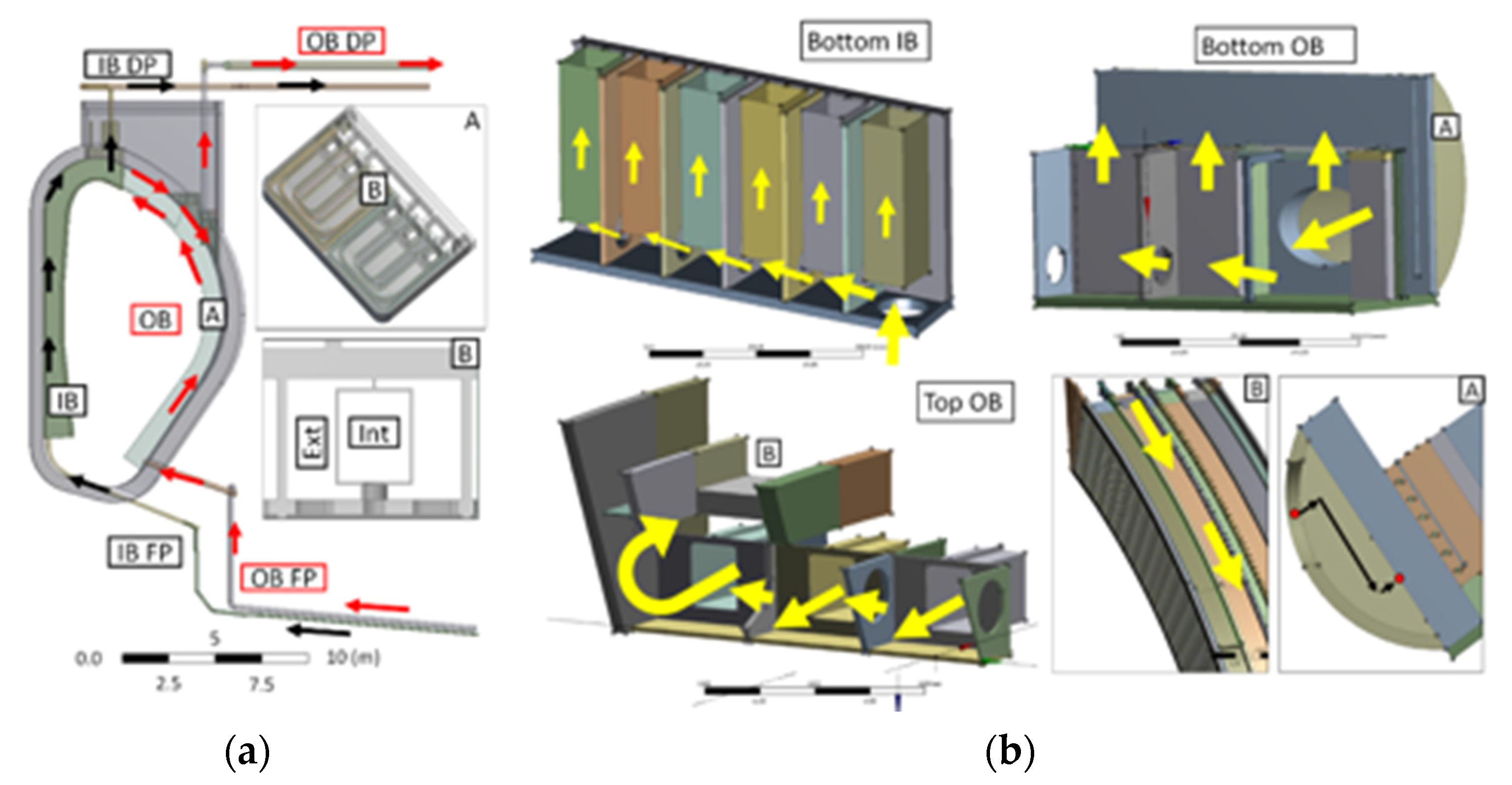
The revised blanket configuration [
11] shown in
Figure 19 was analysed with the semi-analytical model in 2019 for both OB and IB segments [
21]. The results are presented in
Table 2. The objective of this analysis was to assess the impact on the MHD pressure losses of a manifold layout featuring a manifold comprised by co-axial rectangular channels and a more detailed layout for the terminal collectors (linking manifold and connection pipes). Local MHD analyses were carried over to characterize the baseline pressure loss in the manifold and to assess electromagnetic coupling effects [
37].
Coupling effects were found to play a pivotal role in defining both flow features and pressure loss in the manifold since currents leak through the partition wall and cause flow structure rearrangement. This phenomenon was particularly evident at the bottom and top of the manifold. In these positions, either the internal (collection) channel or external (distribution) one is expected to be stagnant. Conversely, it was found that the other channel drove the flow in the duct centre, therefore causing pressure build-up and flow reversal at walls parallel to the magnetic field. Large recirculation zones were expected in the external (distribution) manifold (covering approximately the top 2/3 of blanket poloidal height), and in the collection channel (roughly the lower third of the manifold duct). This latter phenomenon, especially, is a concern for tritium inventory control, since PbLi loaded with tritium could reside for a long time in the manifold channel. Moreover, coupling was found to lead to increase in the manifold pressure loss of approximately 1.59 and 2.41 times the loss in the uncoupled case for, respectively, the distribution and collection manifolds [
37].
The OB manifold and collector layout were found to be characterized by an overall pressure loss of 621 kPa, of which 258 kPa only were ascribable to the manifold and 241 kPa were localized in the top collector and its connection with the drainage pipe, located at 2/3 of the blanket poloidal height. Therefore, a 30% pressure loss reduction was accomplished by the revised manifold, which was even more significant due to the addition of the coupling effects, which were previously neglected in [
36]. However, this was compensated for by larger losses in the collectors caused by more complex geometry and, specifically, the necessity to integrate with the connection pipes through a long BSS duct that caused a final 35% blanket loss increase. Even accounting for this drawback, OB pressure loss were still considered to be acceptable.
The IB pressure loss was found to be affected by larger magnetic field (8 vs. 4 T) and lower velocity due to reduced mass flow rate (5.32 vs. 16.38 kg/s) compared to OB. Moreover, the top IB collector layout was found to be much more streamlined thanks to the possibility to directly drain the breeder from the segment top end. The IB pressure loss was estimated as 618 kPa, of which 450 kPa were ascribable to the spinal manifold and 76 kPa were ascribable to the top collector—values substantially in-line with those reported for the OB and that are likely to be improved in successive iterations.
MHD pressure loss in the piping system is a key concern for overall pressure loss since it constitutes the largest contribution. OB estimates were found to be equal to 613 and 376 kPa for the feeding and draining pipes, respectively (DN200). The same values for the IB were evaluated at 1557 and 260 kPa (DN150). In conclusion, the overall MHD pressure loss on the PbLi loop was estimated at 1.609 and 2.435 MPa for OB and IB, respectively. These figures could be improved by a significant amount through the electrical insulation of the connection pipes with flow channel inserts; this is particularly true for the IB feeding pipe, where an 8 m long pipe is subjected to intense magnetic field and, even for partial insulation, the losses could be reduced to at least half of the present estimate [
21].
In the latest design iteration, the PbLi manifold layout was modified to remove the co-axial channels and revert to a configuration more similar to the one considered in the 2018 study [
36]. This should negatively affect the pressure loss, but a quantitative assessment is not yet available and will be performed in the future.
3.4. Thermo-Mechanical Performance
Concerning thermo-mechanical calculations, several analyses have been carried out to support design activities. Studies have been performed on both local (mainly based on the behaviour of one/few elementary cells and the top cap region) and global models (whole segments). The design development of the WCLL BB has been pursued by analysing the different steady-state loading scenarios that the blanket might undergo and by verifying its structural integrity by means of the design criteria reported in the French nuclear standards RCC-MRx [
38]. In particular, a stress linearization procedure has been adopted in all the structural analyses performed so far.
The structural design of the WCLL BB is strongly dependent upon the over-pressurization (OP) scenario, representing an in-box LOCA due to the breakage of one or more DWTs inside the BZ. In such a scenario, the whole system will be pressurized up to the design pressure, defined as a coolant pressure of 15.5 MPa times a safety factor (initially assumed equal to 1.20 and later decreased to 1.15 [
26]) intended to consider the PbLi/water chemical interaction. The structural integrity under this scenario is mainly guaranteed by the presence of stiffening plates that help the segment box (composed of FW, SW, and BP) to withstand such a high pressure load inside the BZ. A parametric static thermo-mechanical analysis considering the equatorial region of the module was performed, with the varying thickness, pitch, layout, and radial length of the stiffening plates. Thermo-mechanical analyses were conducted while assuming, for the assessed OP scenario, a uniform pressure of 18.6 MPa (i.e., the nominal pressure of 15.5 MPa times 1.2) on the BZ internal surfaces and the water-wetted surfaces (namely the FW channels and DWTs), as well as considering a non-uniform thermal strain field inferred from calculations reported in [
39]. As reported in [
17], the best configuration was found to be that characterized by a vertical and horizontal plate thicknesses of 12 and 10 mm, respectively, and a pitch between two horizontal plate of 135 mm. Moreover, the best configuration allows one to save steel while increasing the breeder amount with an increase of the neutronic performance. In particular, the steel amount in the optimized configuration was found to be 88.7% of the previous reference design.
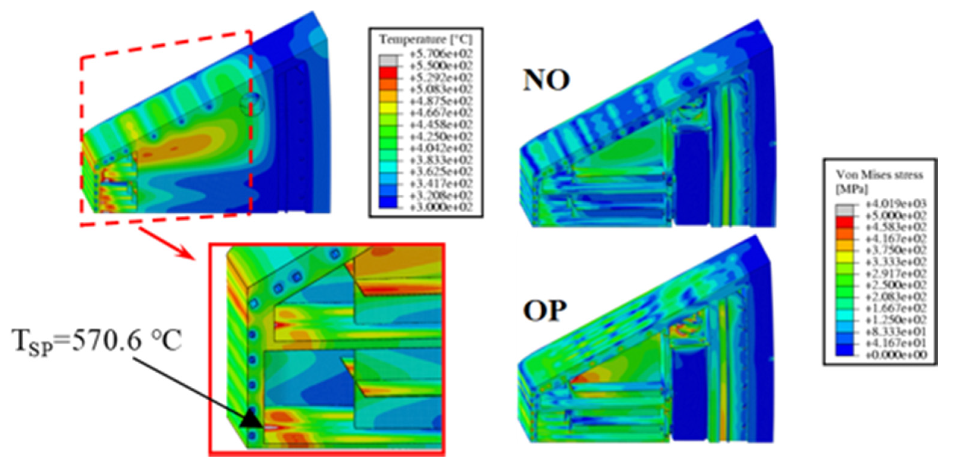
Concerning local analyses, a dedicated study was performed in order to design the upper peripheral area of the segment in detail. In particular, attention was paid to the top cap (TC) of the COB segment [
22]. Due to the complexity of the geometry and the non-uniform heat load distribution, a methodology based on a design-by-analysis approach was followed. Preliminary analyses led to the selection of a TC thickness of 40 mm (as reported above) and a geometric layout for its cooling channels (with a square cross-section of 10 × 10 mm
2) able to maintain the TC temperature below the EUROFER limit value of 550 °C. A preliminary layout of the DWTs housed in this region was proposed, and a further set of thermo-mechanical analyses were performed under both the normal operation (NO, characterised by a pressure of 15.5 MPa onto water-wetted surfaces and 0.5 MPa onto BZ internal surfaces) and OP steady-state loading scenarios. Finally, a stress linearization procedure was conducted along some paths located within the most stressed areas of the model in order to check the fulfilment of RCC-MRx design criteria [
38]. The obtained results highlighted that some hot-spots are predicted (maximum temperature equal to 570.6 °C) within SPs, suggesting the necessity of a further review of the BZ cooling scheme, whereas the TC maximum temperature was found to be well-below the prescribed limit (
Figure 20). Concerning the stress field (
Figure 20) arising within the model, some of the design criteria were not fulfilled along a few paths. A more exhaustive description of adopted models and results was reported in [
22]. Here, it has to be underlined that the proposed TC geometric layout seems to be able to fulfil the prescribed design requirements, though further investigations and optimizations are necessary to properly design the adjacent elementary cells.
Regarding the global analyses of a whole BB segment, the COB behaviour undergoing a vertical displacement event-up (VDE-up) was assessed [
40]. A structural assessment of the WCLL BB that considered these updated loads, as well as the new proposed attachment system and VV reference temperature, was carried out [
41]. In addition to NO and OP loading scenarios, EM loads derived from a VDE-up event were considered for a proper steady-state loading scenario.
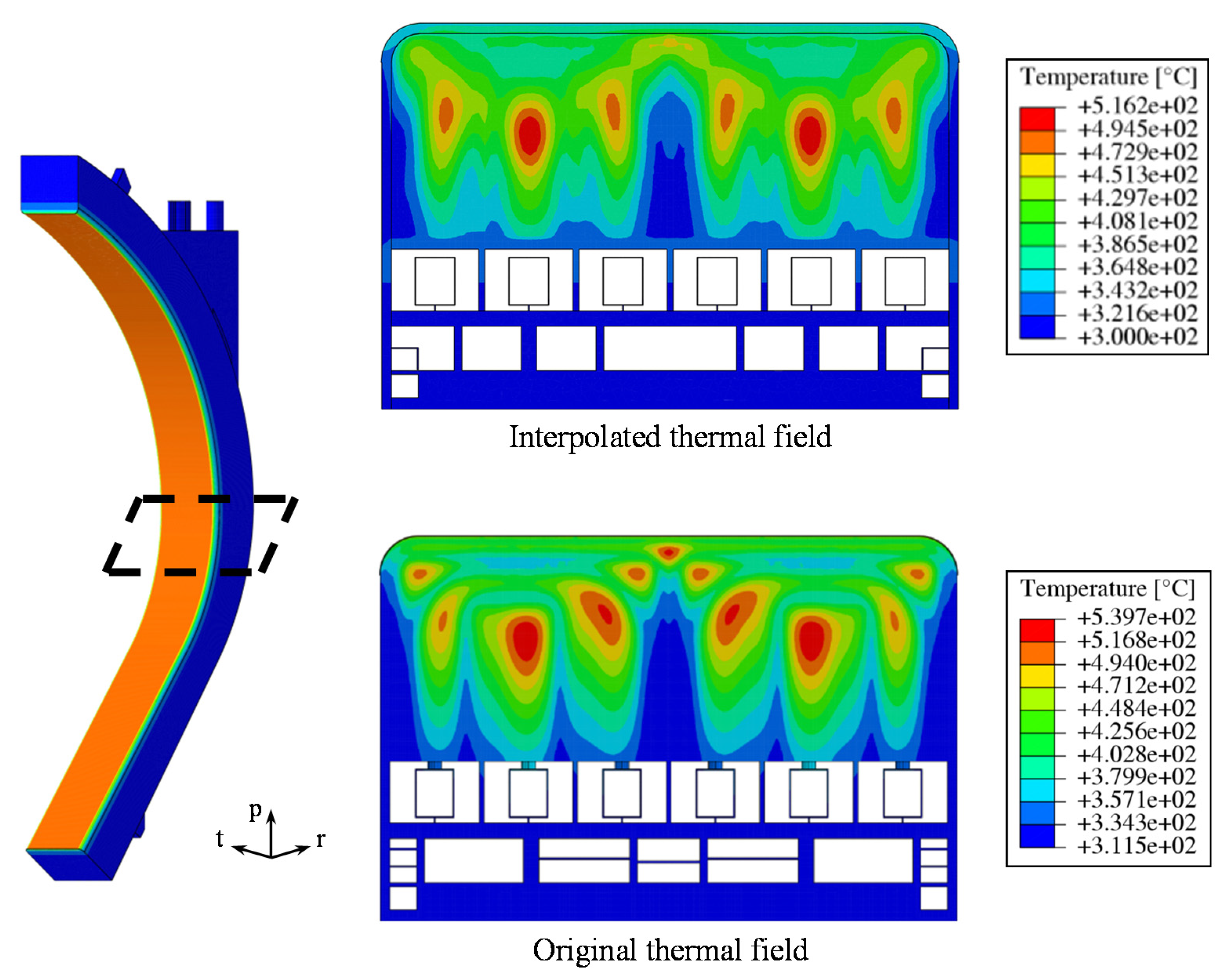
Calculations were performed for the COB segment while adopting ad hoc procedures for both the implementation of a thermal field and EM loads. Indeed, the thermal field calculated in detail for a single outboard equatorial elementary cell was poloidally extended to the whole COB segment by adopting thirteen different interpolating functions (
Figure 21) of the radial and toroidal variables. In this way, it was possible to consider thermal deformations occurring to the COB segment without performing additional thermal analyses that would be very onerous from a computational point of view. Finally, in order to investigate the impact of the tungsten armour on the thermo-mechanical response of the COB segment, two different geometric layouts (segment with and without W armour) were set-up and assessed under the three considered loading scenarios.
As prescribed in [
26], the design pressures, calculated as the nominal pressure multiplied by a safety factor of 1.15, were adopted for this study. Therefore, a coolant design pressure (P
des,coolant) of 17.825 MPa and a breeder design pressure (P
des,breeder) of 0.575 MPa were set. Concerning the NO and VDE-up scenarios, P
des,coolant was imposed onto all the coolant-wetted surfaces, while P
des,breeder was assumed to act on the breeder-wetted surfaces. For the OP loading scenario, P
des,coolant was considered for both coolant and breeder-wetted surfaces because this scenario represents over-pressurization conditions due to an in-box LOCA event. Moreover, in contrast to the past, EM loads were considered in all postulated scenarios. In particular, static ferromagnetic loads (Maxwell’s forces) were considered for the NO and OP scenarios in addition to pressure, gravity, and thermal loads. In the case of a steady-state analysis, EM loads related to a single instant of time (time-step) were considered and implemented. In particular, during normal operation, the assumption to disregard Lorentz’s forces due to their low contributions is valid, and the only contribution is provided by Maxwell’s forces. Instead, during a plasma vertical displacement event simulated in the VDE-up loading scenario [
40], the impact of Lorentz’s forces was found to be not negligible and must be taken into account in the future. Moreover, throughout a plasma disruption, EM loads undergo great variations, so EM loads referring to two time-steps were checked and two equivalent static analyses (neglecting dynamic effects) were conducted. In particular, since the radial direction is the main component of EM loads, the time-steps related to the maximum radial force and the maximum radial moment were considered.
Steady-state analyses were conducted in order to assess the thermo-mechanical behaviour of COB segment in both configurations with and without the W armour. In order to evaluate the thermo-mechanical behaviour of COB in the different considered scenarios and to verify whether the RCC-MRx design criteria [
38] were fulfilled, a stress linearization procedure was carried out along the most critical regions individuated within the model.
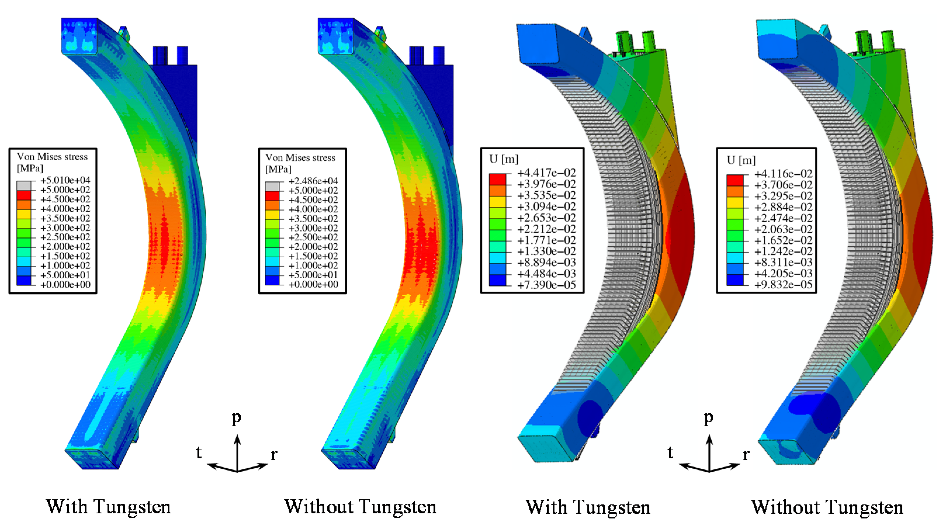
The results obtained for the different assessed scenarios showed that the most of the investigated domain experienced stress values lower than 500 MPa. In addition, in the configuration without tungsten, an average stress level greater than the case where the armour is considered was predicted. As an example, Von Mises equivalent stress fields for the VDE-up scenario at t = 11.52 s (maximum of radial forces) are reported in the left part of
Figure 22.
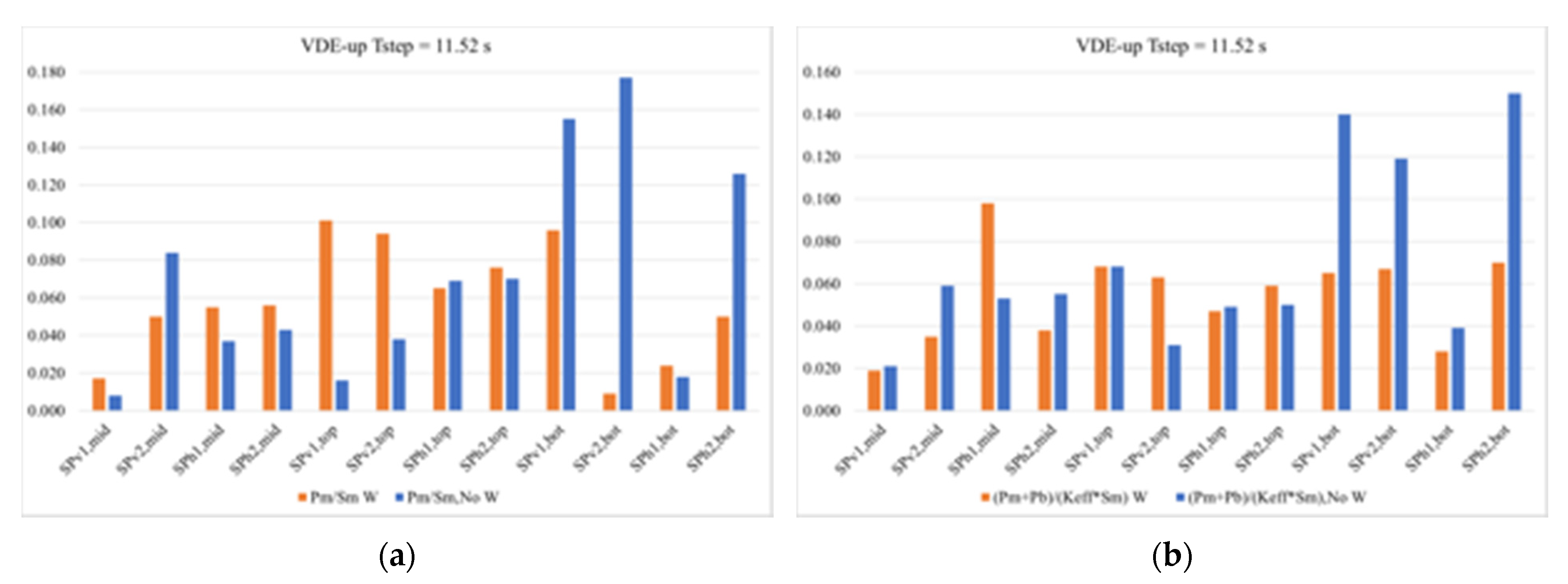
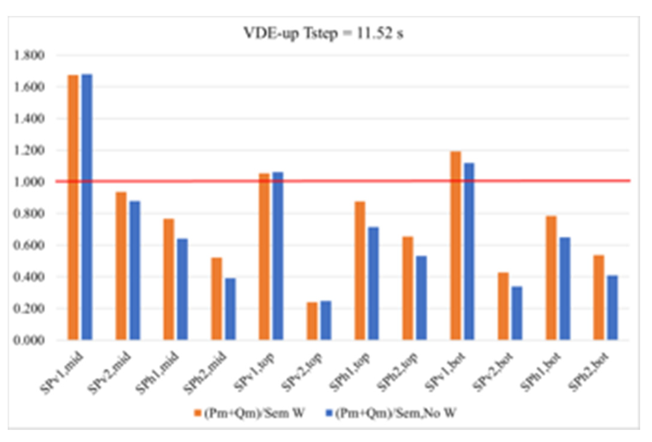
Stress linearization procedures highlighted that not all assessed RCC-MRx criteria were fulfilled along the considered paths, particularly regarding paths considered within the poloidal–radial SPs, which were the most stressed. Furthermore, none of the cases fully verified the criterion against the immediate plastic flow localization, which considers secondary stresses. As an example,
Figure 23 and
Figure 24 report the verification, along the considered paths, of three RCC-MRx design criteria, namely immediate excessive deformation (IED), immediate plastic instability (IPI), and immediate plastic flow localization (IPFL) for VDE-up at t = 11.52 s.
Finally, concerning the displacement field, a remarkable displacement along the radial direction was observed. This trend was probably due to the fact that the attachment system did not use any support in the equatorial region to prevent the radial displacement of the segment, thus showing a very large deformation. In addition, the configuration with the W armour showed the highest maximum displacements values. As an example, displacement fields, with an isotropic amplification factor equal to 30 superimposed on the un-deformed layout, are reported in the right part of
Figure 22 for the VDE-up scenario at t = 11.52 s. The full set of thermo-mechanical results was more exhaustively reported and discussed in [
41]. Here, it has to be underlined that the analysis results have shown that further studies need to be carried out. In particular, the COB supporting system needs to be reviewed in order to avoid too-large displacements and improve the segment’s thermo-mechanical behaviour.


 ,
, 


