Review

Non-Destructive Testing Applications for Steel Bridges

by
Seyed Saman Khedmatgozar Dolati
1,*,
Nerma Caluk
1,*,
Armin Mehrabi
1 and
Seyed Sasan Khedmatgozar Dolati
2
1
Department of Civil and Environmental Engineering, Florida International University, Miami, FL 33174, USA
2
Department of Civil and Environmental Engineering, University of Texas at San Antonio, San Antonio, TX 78249, USA
*
Authors to whom correspondence should be addressed.
Appl. Sci. 2021, 11(20), 9757; https://doi.org/10.3390/app11209757
Submission received: 28 September 2021 / Revised: 12 October 2021 / Accepted: 15 October 2021 / Published: 19 October 2021

Abstract

:
The growing population and increasing demand for surface transportation have highlighted the importance of maintaining safe and reliable civil infrastructures for daily use. Among all civil infrastructures, bridges are one of the most important elements in the transportation system. As such, to prevent any failures caused by aging and environmental impacts, bridges require periodic inspections. This becomes even more critical due to climate change and its effect on bridges, especially in the coastal regions. Most of the inspections conducted incorporate the visual type of evaluation due to its simplicity. However, with the current developments in new technologies, there is a need for more advanced techniques of structural health monitoring (SHM) methods to be incorporated in the maintenance programs for more accurate and efficient surveys. In this paper, non-destructive testing (NDT) methods applicable to steel bridges are reviewed, with a focus on methods applicable to local damage detection. Moreover, the methodology, advantages and disadvantages, and up-to-date research on NDT methods are presented. Furthermore, the application of novel NDT techniques using innovative sensors, drones, and robots for the rapid and efficient assessment of damages on small and large scales is emphasized. This study is deemed necessary as it compiles in one place the available information regarding NDT methods for in-service steel bridges. Access to such information is critical for researchers who intend to work on new or improved NDT techniques.

1. Introduction

Because of an increased reliance of communities and businesses on surface transportation, and with the presence of ever-increasing environmental impacts caused by aging, maintaining the safety and reliability of civil infrastructures has become a critical issue. Among all civil infrastructures, bridges can be deemed as the most affected type. From over 617,000 accounted bridges in the United States, about 42% of those bridges are at least 50 years old, and 7.5% of them are considered structurally deficient. Although the number of structurally deficient bridges has been declining over the past 50 years, the rate of their improvement is still considered slow [1]. Out of the total number of bridges in the United States, around 33% are steel bridges [2]. A similar condition also exists for bridges in other parts of the world. Throughout the years, steel bridges have been evolved and adapted by their designers, eliminating issues that were consistently reoccurring in the designs. However, there are still many issues that can decrease the structural integrity of a steel bridge, with corrosion being the most prevalent, followed by fatigue and fracture in sensitive connections, some exacerbated by welding issues. Accordingly, bridges must be inspected periodically for the on-time detection of possible structural damage and apply the needed repairs before the damage becomes significant and costly. The National Bridge Inspection Standards (NBIS) mandates that all bridges with a span of longer than 20 ft and located on public roads need to be inspected every 24 months by a qualified bridge inspector [1,3].
Over the years, various techniques have been implemented for the structural health monitoring of the bridge systems. Among various methods, non-destructive testing (NDT) methods incorporate the non-invasive testing of structural components and structural systems without causing any damage, changing their material composition or shape of the inspected components. The Federal Highway Administration (FHWA) also defines NDT as a “means of analyzing and assessing the condition of various structural components of in-service highway infrastructure assets—pavement, bridges, and tunnels—without impairing their future usefulness” [4]. These methods bring an innovative and rapid mode of inspection with which to analyze and diagnose structural deficiencies such as cracks, fatigues, delamination, voids, and corrosion. Various non-destructive testing (NDT) methods have been implemented for the inspection of bridge elements. The required type of NDT method differs from one bridge to the next, depending on the structural type, the environment, and the preference of the owner.
This paper compiles in one place all the information regarding the application of NDT methods for steel bridges. Although both global and local damage detection methods are discussed, the focus of this paper is on the methods applicable to local NDT methods. As such, the methodology, advantages, and disadvantages of each technique are thoroughly investigated. Furthermore, recent innovations in this regard, including the application of drones, sensors, or robots for rapid and efficient assessment of damages on small and large scales, are presented. This is an attempt to compile in one place all the NDT techniques, including state-of-the-art and advanced techniques, for the inspection of steel bridges. It aims to keep researchers up-to-date with existing methods and pave the way for further innovations in this regard. Importantly, this study can help engineers and inspectors select the most proper NDT methods at the site, potentially saving considerable cost and time.

2. Need for Inspection of Steel Bridges

Steel bridges constitute a substantial portion of national wealth. Unchecked damages and the potential failure of these critical infrastructure links could not only have a significant economic impact, but also threatens public safety. As such, they should be inspected between short intervals to prevent the exacerbation of potential damages and failure. Typical damages of in-service steel bridges include corrosion and the loss of cross-section, delamination, cracks, wear, and surface blemishes (Figure 1). These damages, after detection, should be repaired or appropriately rehabilitated to prevent future catastrophic failures. It goes without saying that detecting the damages is the first step in this process.
Most of these damages in their advanced stage can be detected easily with a visual inspection. However, the detection of small and subsurface cracks and damages in deficient welded connections require inspection and testing techniques with capabilities above and beyond visual inspection. To address this, various NDT methods have been practiced over recent decades. The type of NDT method required for the inspection should incorporate the most practical and cost-effective technique to successfully assess the condition of the structural components and to determine the need for maintenance and repair action. In addition to a familiarity with, and skill in, the use of these various available methods, the inspector needs to be aware of the environment in which the inspection takes place, as well as the bridge section that is under survey, to determine the proper procedure.

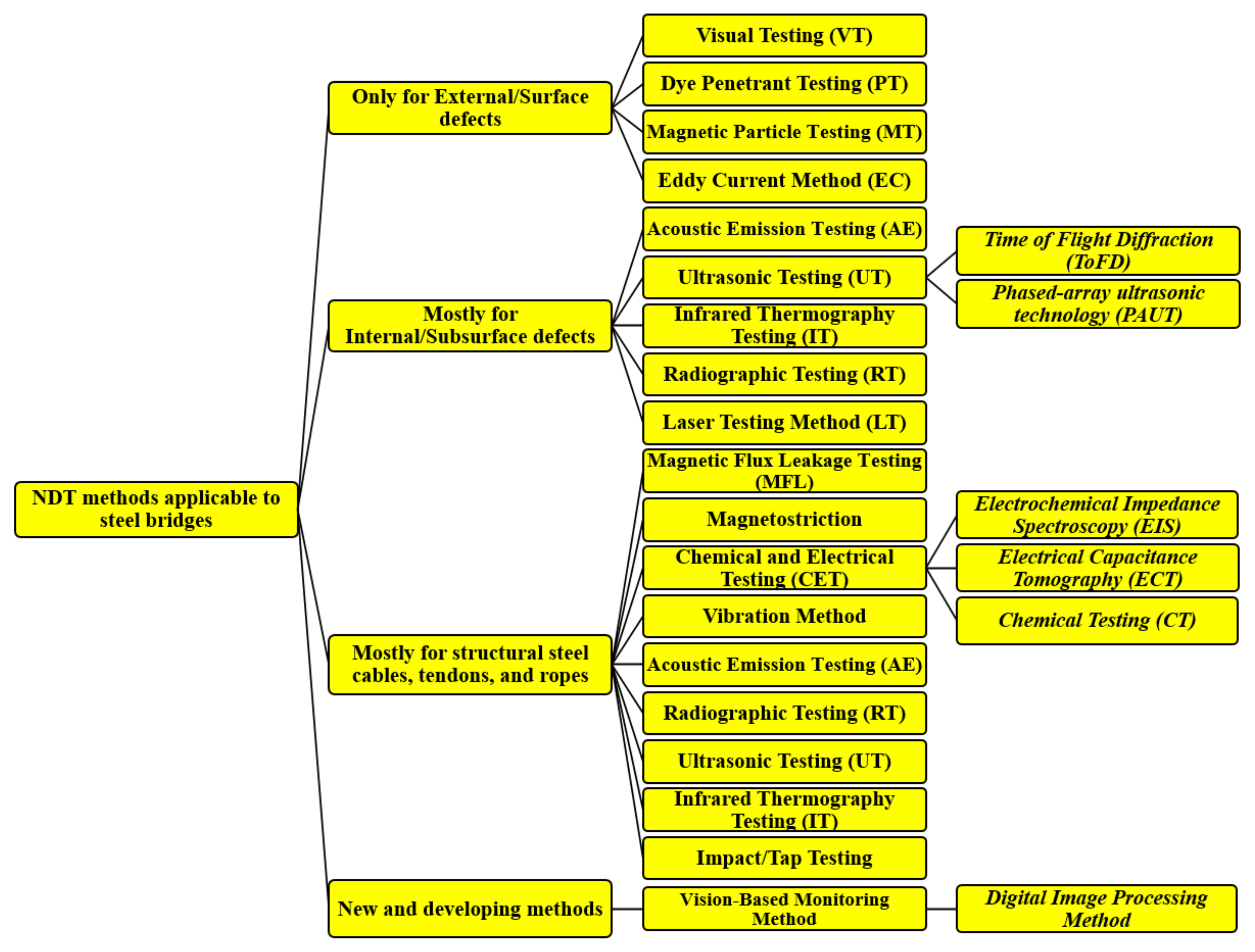
3. NDT Methods with Potential Application to Steel Bridges

The bridge damage discussed above can be categorized into two groups: surface and subsurface damages. One of the major factors that distinguish NDT methods is their ability to detect internal/subsurface defects or external/surface defects, considering that some methods can detect defects both beneath and on the surface. Considering the type of steel elements, type, and location of damages, and the capability of NDT methods in detecting the internal and external defects, testing methods applicable to steel bridges can be categorized (Figure 2) and discussed as follows:

3.1. Test Methods Applicable Only to External/Surface Defects

NDT methods discussed in this section can be implemented to detect defects and damages occurring on the surface of steel bridges. These methods can be considered as simple to apply and easy to interpret when compared to methods for internal defects. Despite the relative simplicity of these methods, the inspectors should be experienced and well trained. These testing methods are described as follows:

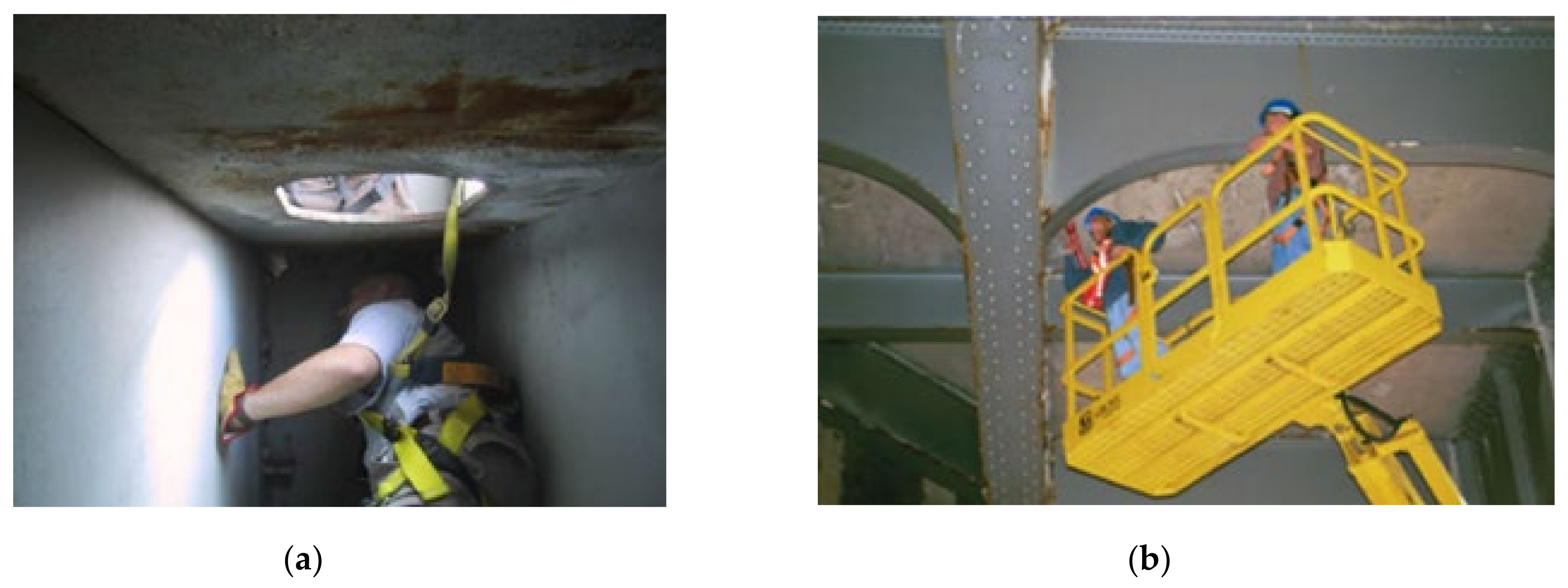
3.1.1. Visual Testing (VT)

This technique is the most common form among all NDT methods due to its simplicity. Although most of a visual inspection is performed with the naked eye, some cases may require visual aids such as magnifiers, binoculars, scopes, and borescopes. The inspector in this case needs to be experienced and familiar with the types and levels of damage in the steel. This is the most economical and fastest method of inspection [11]. However, because of the subjectivity of the visual inspection method, different results could be reported by different inspectors. Visual inspection limits the inspector to the surface defects that are sufficiently noticeable [12]. Different conditions can affect the inspector’s judgment and focus, including traffic, working at a height, limited visual angle, lighting conditions, and multitasking with other tasks for bridge element rating [10]. These factors can be problematic for the inspectors to decide whether a flaw should be considered a defect and if it requires follow-up action. An example of challenging visual inspection is shown in Figure 3, where the lack of lighting and height can be of concern.

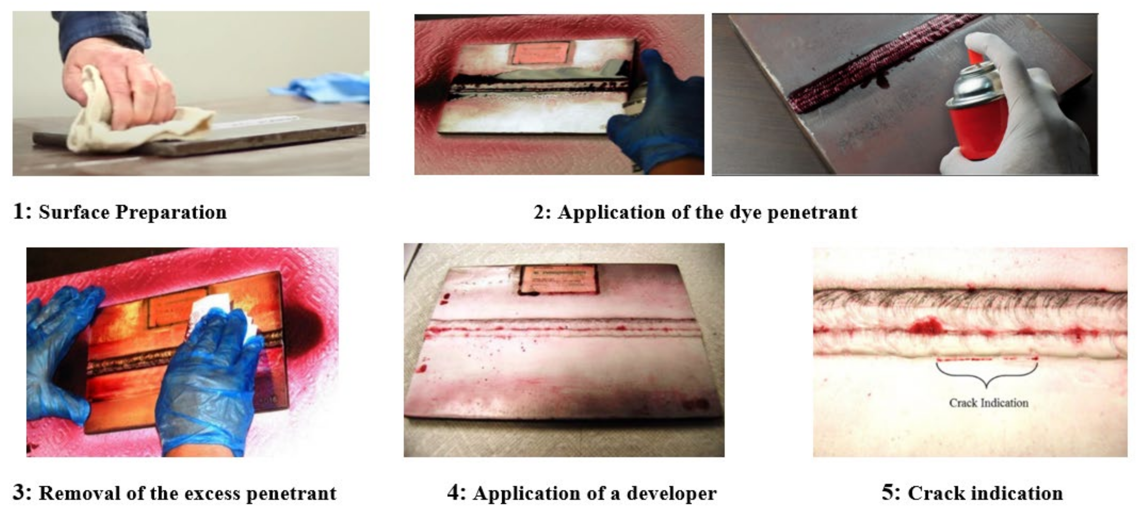
3.1.2. Dye Penetrant Testing (PT)

The Dye Penetrant Testing (PT) is an NDT method and is used to detect and monitor surface cracks, welded details, and gusset plate connections in steel bridge members. This method is inexpensive and simple, and can be implemented for the confirmation of the visual inspection. However, its process is time-consuming and, as a result, may not be cost-effective where multiple locations need to be inspected. The PT method relies on dye liquid that is applied onto the surface with the ability to penetrate a crack, void, and other surface defects in the element [10,13,14,15]. The penetrant dye is usually packed in a kit that contains the required chemicals in three aerosol spray cans, i.e., a cleaner, a penetrant, and a developer. Each of the cans is related to a specific step of the process [4]. Figure 4 indicates the steps needed for the application of PT to provide the inspectors with accurate and valid results [13,16,17]
The dye penetrant method is highly sensitive, portable, and can detect even the smallest surface discontinuities. It can be applied to a variety of base material and is suitable for complex shapes. However, there are some disadvantages for this method: It is not suitable for inspecting the elements with a porous surface; it requires caution in pre-cleaning, chemical handling, and removal of the excess penetrant; and the inspector needs to access the tested components to safely conduct the whole inspection [17].

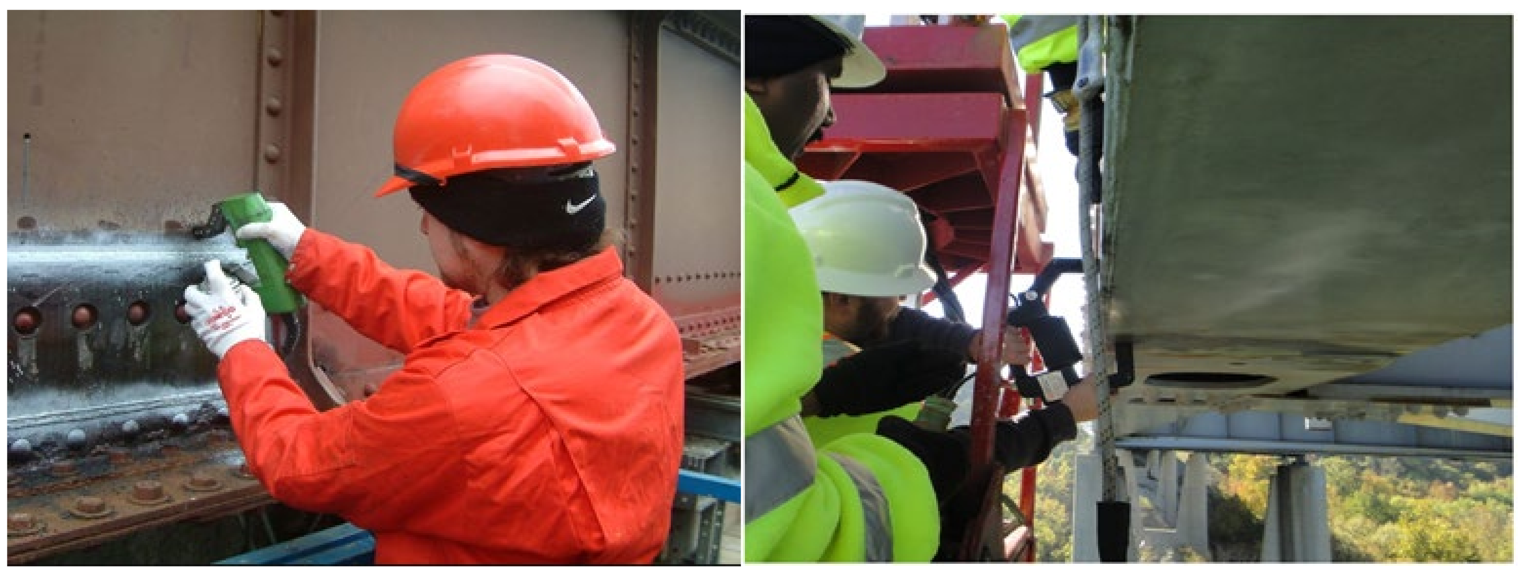
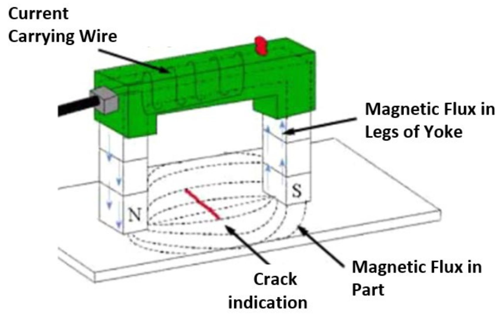
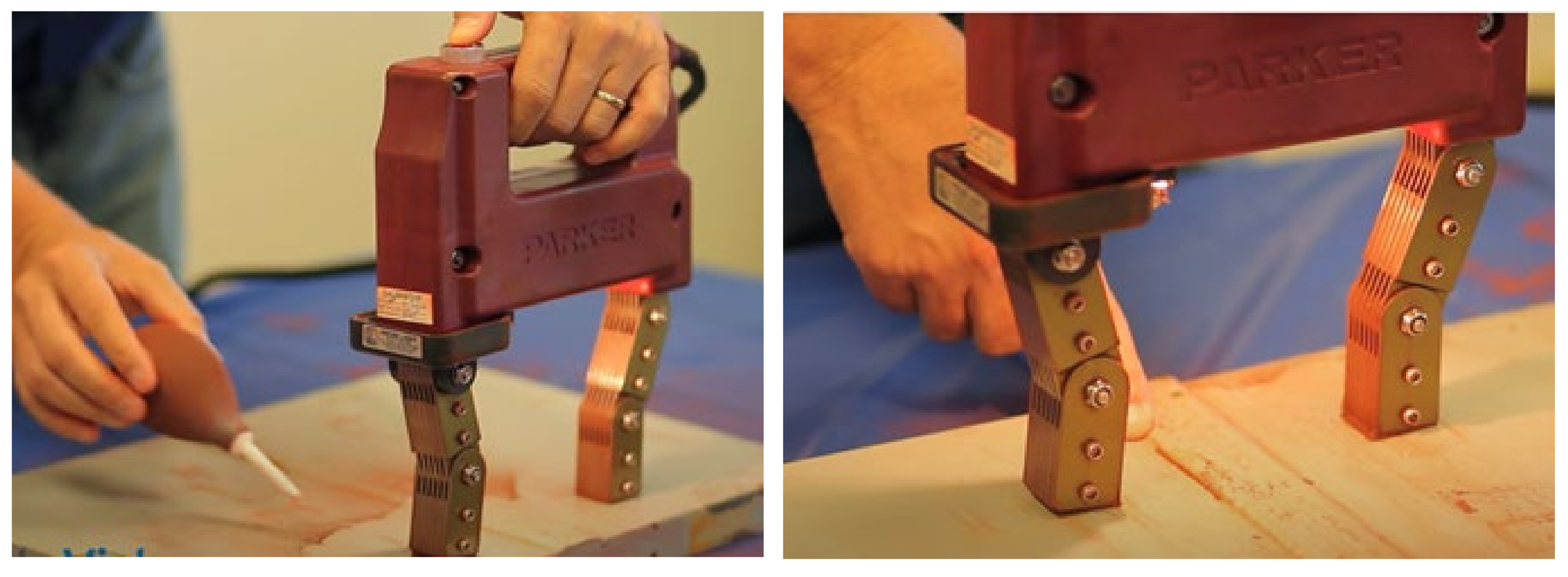
3.1.3. Magnetic Particle Testing (MT)

This method can be implemented to detect surface and near-surface internal flaws in steel bridge elements (Figure 5). Compared to the PT method, its application is faster and less costly, and requires less surface preparation. In this method, after cleaning the surface of the test component from oil, grease, or any other contaminations, a magnetic yoke is placed on, producing magnetic fields between the yoke probes (Figure 6). This creates magnetic flux lines which flow between the legs of the yoke. As such, any defect interrupting the magnetic flux lines produces a localized area of flux leakage, consequently changing the formation of iron particles that is spread on the suspect area. There are two methods for applying this technique: implementation with dry iron particles or wet iron particles. For dry MT, iron powder is applied to the surface of the test area while the magnetic force is applied by the yoke. Then, the surface is lightly blown using a bulb applicator, removing additional iron particles. In response, the particles are absorbed and clustered at flawed sites (magnetic leakage areas), creating a clear indication (Figure 7). For the wet MT application, the iron particles in a combination of water or oils are sprayed to the test areas. Other steps for the application of wet MT are the same as dry MT. Other works can be referred for more detailed procedures and practices [18,19].
MT is a practical option for exterior/surface flaws for steel bridges. This method is simple and requires minimum training for inspectors. However, this technique has some disadvantages, including issues for irregular surface finishes, the need for lane closure for performing the test, and its being not applicable to non-ferromagnetic material. The coating thicker than 2 mils should be removed before applying the tests [10].

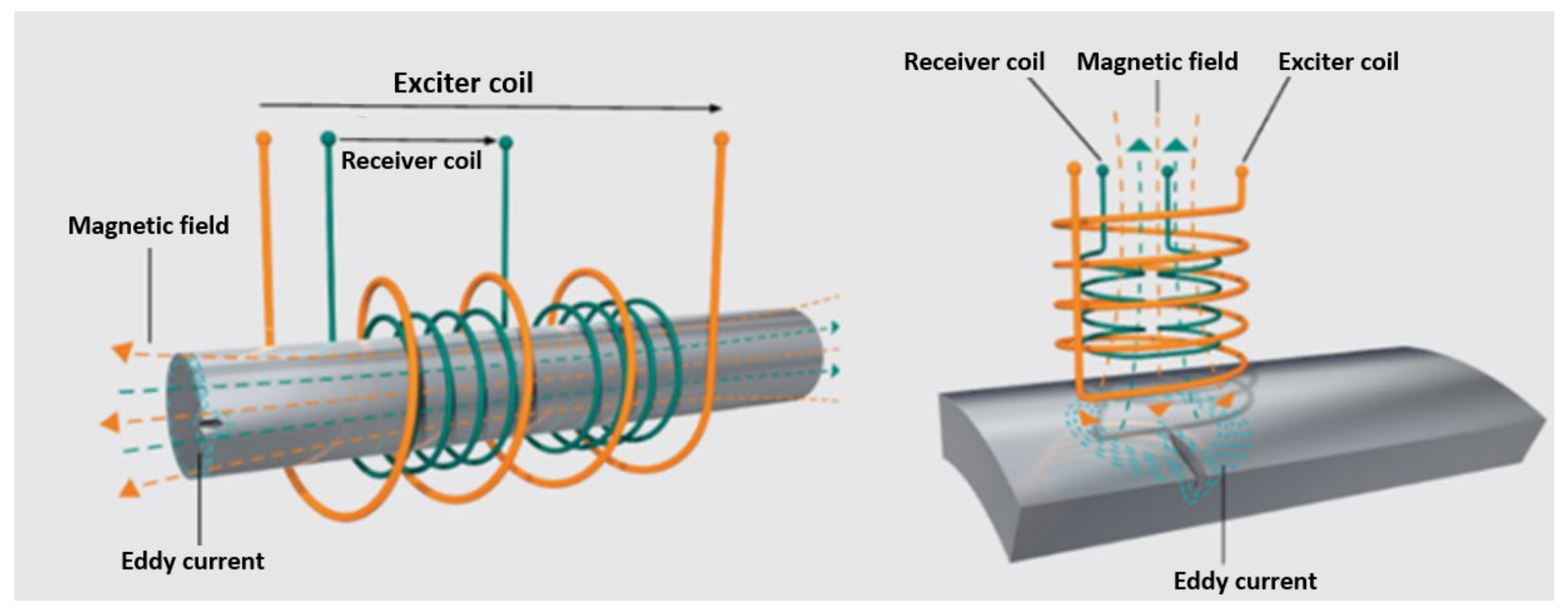
3.1.4. Eddy Current Method (EC)

Eddy current (EC) method represents a non-destructive electromagnetic test that uses energized probes. This technology uses eddy coils placed side by side on the probe. When the probe is placed on the test piece, a dynamic magnetic field is created around the probe. This magnetic field produces eddy currents in the test piece centered on the probe. The currents induced on the test piece oscillate in a circular pattern and flow in a direction opposite to the current in the coil. Because a specific magnitude and phase are generated by the eddy current, any cracks or discontinuities affect the magnitude and phase, therefore pointing to a defect. Figure 8 shows an example of EC practiced for the purpose of detecting a flaw on a steel element.
The EC method has initially been used in the aerospace and petrochemical industry for the non-destructive testing of non-ferromagnetic cylinders, metallic pipes, rods, bars, etc., to detect cracks, corrosion, and other material defects. The EC method has been expanded to civil engineering, specifically in the non-destructive testing of steel bridge components [25].
Compared to MT and PT, the eddy current method is faster and requires less surface preparation. Accordingly, it is a time-efficient process and can be implemented where multiple inspection sites are present on a bridge. This method is practical for the detection of flaws through both non-conductive and conductive coatings.

3.2. Test Methods Applicable to Internal/Subsurface Defects

The methods discussed in this section are normally implemented to detect internal/subsurface defects in steel elements; however, these methods are also applicable in the detection of external/surface defects. Their application is mostly used for the sizing and characterizing of the defects previously indicated by external/surface NDT methods; the inspection of test sites in which potential for internal damage exists, including pins, questionable welds, weld repairs, or impact damage; and the monitoring of the size of the subsurface to assess progressive fracture and determine the follow-up action. These techniques are slow and require experienced operators, special training, and costly equipment.

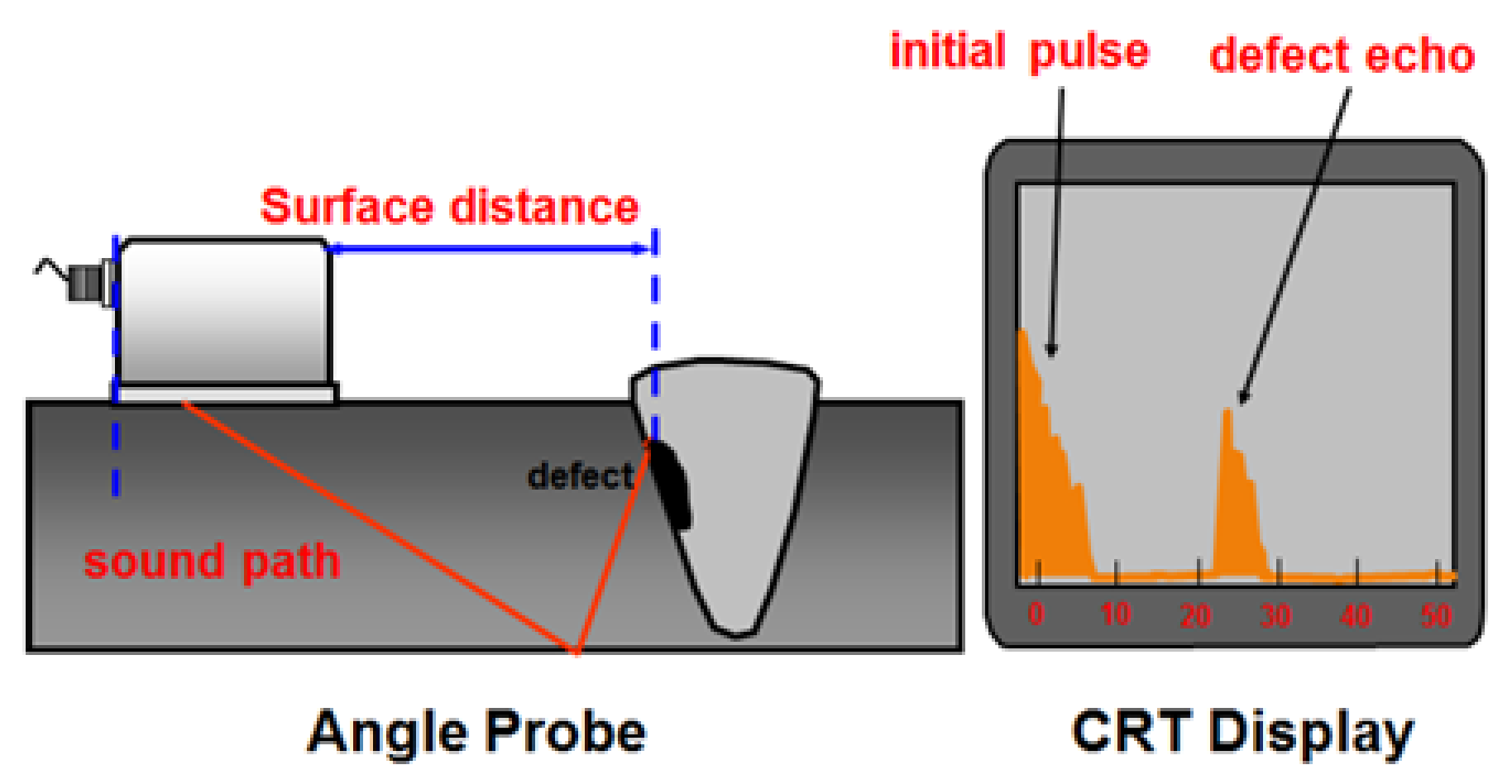
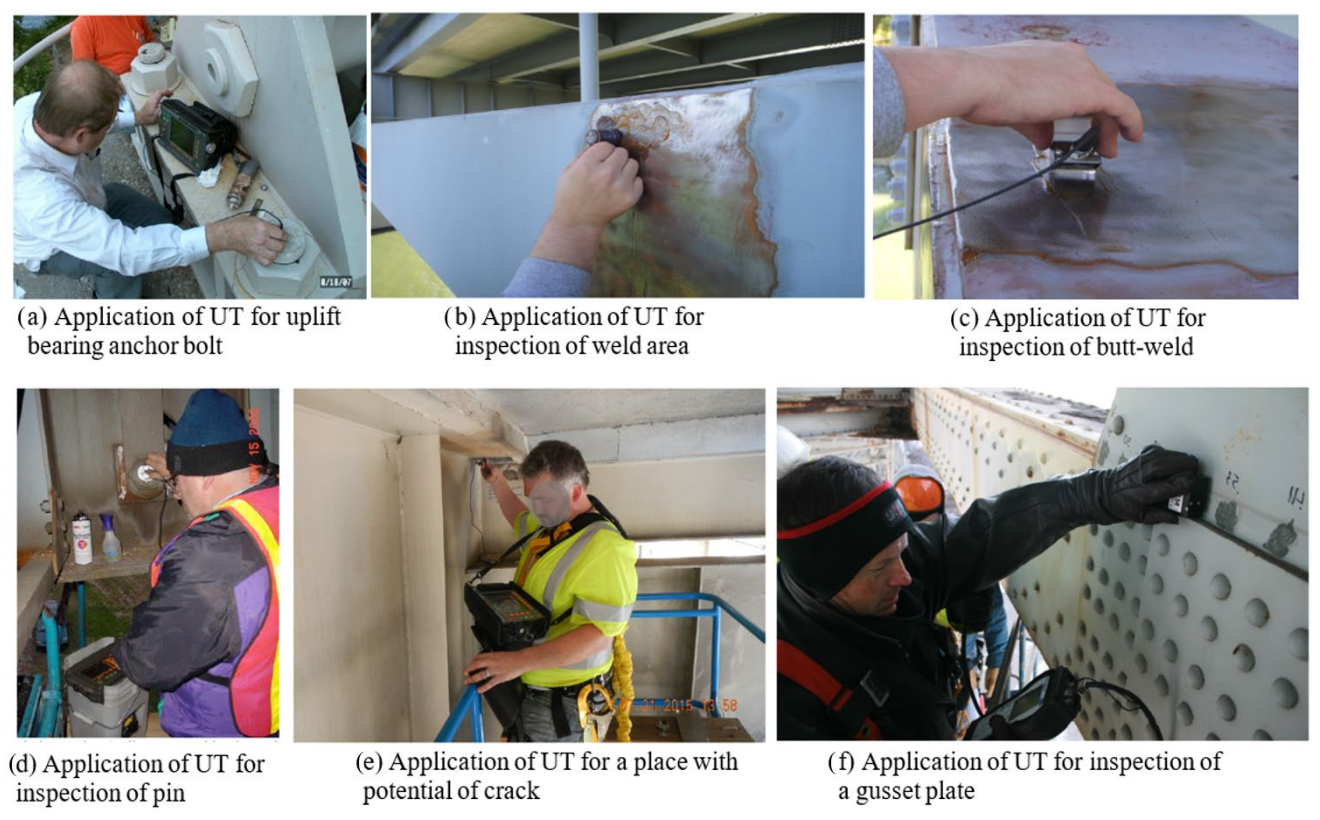
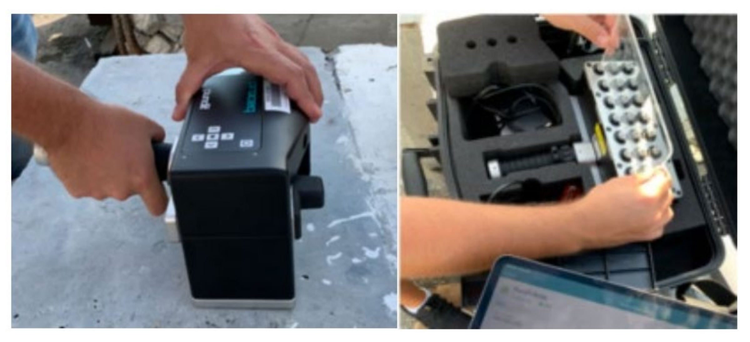
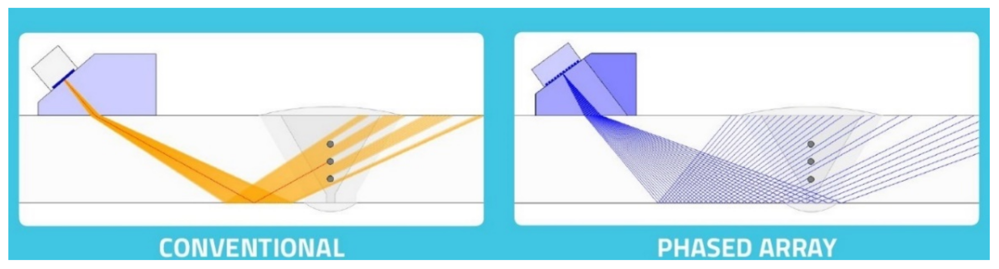
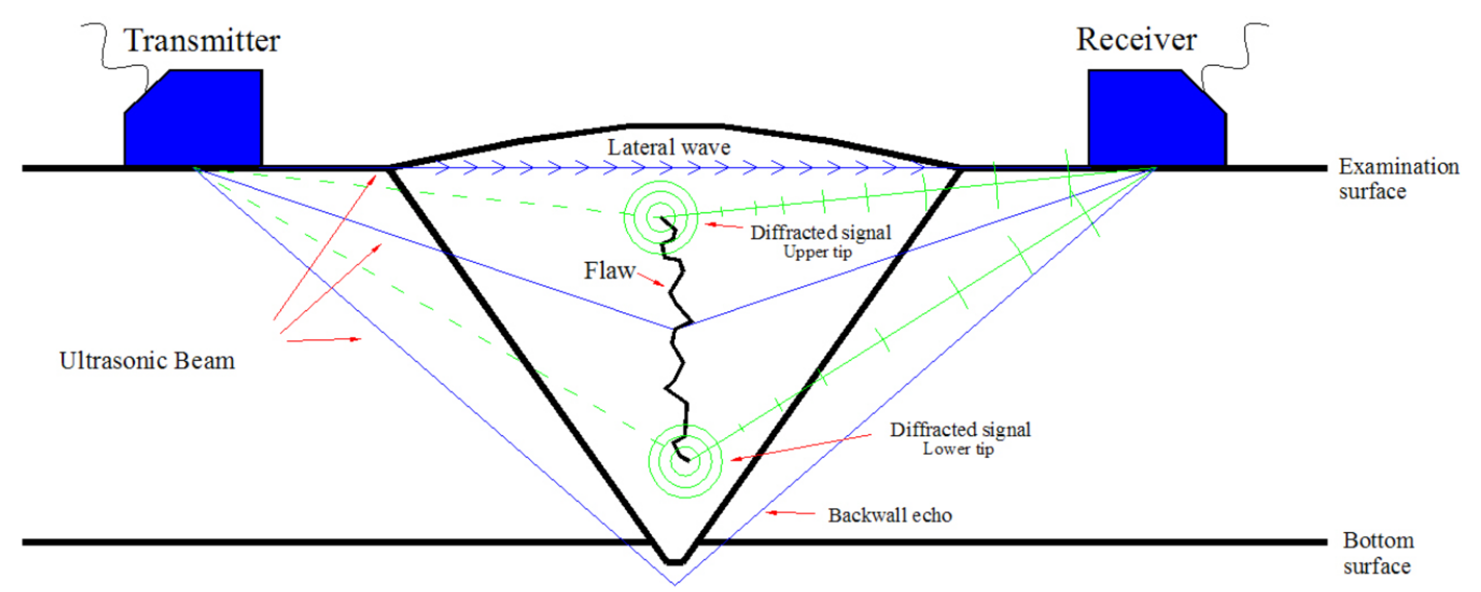
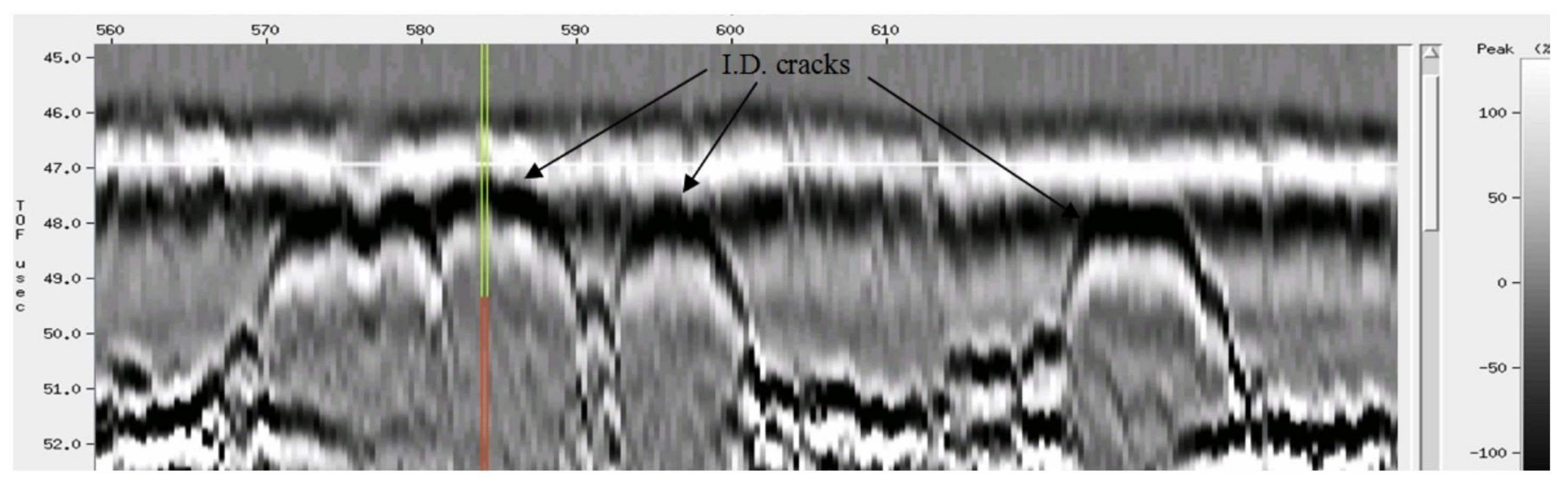
3.2.1. Ultrasonic Testing (UT)

The application of Ultrasonic Testing (UT) to damage detection in steel bridges is widespread. It can be used to detect subsurface volumetric flaws, including slag inclusions and cluster porosity, surface-breaking flaws (e.g., cracks), and material thickness, to measure corrosion and construction errors. It is the most practical NDT method for detecting planar defects, including cracks, a lack of fusion, and a lack of penetration. It has also been implemented for wire break detection at anchorage zones for stay cables and tendons [10]. The UT method uses tools that include a pulser–receiver, electronic signal controls, display screen, transducers, lead wires, reference gages, and a couplant. Sometimes, surface preparation is required, which requires wire brushes, grinding disks, scrapers, and hammers. In this method, the structural component is tested using ultrasound waves at frequencies more than the audible ranges [26,27]. The reflection of waves on the UT monitor indicates the exact distance of any subsurface/internal flaws from the surface [28] (Figure 9).
Specific amplitudes and frequencies of the electronic pulses are generated through the lead wires that are connected to piezoelectric crystal probes. For steel elements, the frequency is typically between 2 and 5 Hz. Two types of transducers exist depending on the kind of waves that are generated: straight beam and angle beam transducers. Straight beam transducers generate compression waves consisting of alternating layers of steel atoms that expand and compress due to the of the elastic motion. Angle beam transducers generate shear waves that oscillate at right angles to the direction of the wave motion [10]. The presence of air gaps between the contact of UT transducers and the surface of a tested piece may cause wave scattering. Accordingly, a gel couplant is applied to the surface to strengthen the in-situ bonding and to prevent wave scattering [30]. Figure 10 shows the application of UT for the steel bridges. UT is considered a fast NDT method, and its cost is moderate. Its accuracy in detecting defects, portability, and high safety are other advantages of this technique. However, this method is less effective for inspecting very thin components, fragile materials, and elements with a complex geometry [31]. In order to enhance the capabilities of the ultrasonic tests, several methods have been developed; the following are more details of these techniques.
Phased-array ultrasonic technology (PAUT)— Phased-array ultrasonic technology (PAUT) is one of the advanced UT methods developed to detect cracks located at different depths, with random orientation probes at fixed conditions (Figure 11). The main property of PAUT is its computer-controlled excitation of individual elements with a multi-element probe, which can generate an ultrasound focused beam with the capabilities of modifying the beam parameters [32] (Figure 12). These parameters include the beam angle, focal distance, and focal spot size, allowing this technique to detect cracks in various orientations located away from the beam axis [33].
PAUT is known for its simplicity in implementing multiple transducers. This type of ultrasonic method is not only faster and more convenient than conventional monolithic technology, but it also possesses better accuracy. Further capabilities include easier accessibility to out-of-reach components, shorter inspection time, and the detection and measurement of small stress corrosion cracks. Sometimes, the limitation in orientation for the path of the ultrasonic pulse makes it difficult for PAUT to fully obtain an image of cracks and defects. It also requires costlier equipment compared to conventional UT.
Time of Flight Diffraction (ToFD)— To address the issues with orientation when using PAUT, ToFD was invented, which uses diffraction instead of reflection. A ToFD transducer generates pulsed ultrasonic waves [32,35,36,37], which are diffracted at a certain degree due to the irregularities in the inspected component. After the diffraction, waves are then collected by the receiver on the other side of the component. The image is then generated, containing the size and location of the cracks and defects, using the difference in the flight time of the ultrasonic waves that traveled from the transducer to the receiver (Figure 13). This type of ultrasonic technology is preferred over PAUT when the objective is to find defects and flaws, regardless of their orientation. ToFD can also be used to inspect welded overlays and heat-affected zones. Furthermore, it is considered to be one of the fastest non-destructive testing methods as it only requires one scan for detection. An example of the reading of weld cracks with ToFD can be seen in Figure 14 [36,37,38].
However, the ToFD method has shortcomings, including the possibility of presenting lateral wave dead zones, timing errors, off-axis errors, or resolution errors on the image if only a single scan has been performed on the component. This issue can be solved by implementing the PAUT to vary the wave angle, width, and entry point. Combining ToFD with PAUT gives the inspectors a more reliable and efficient scanner [39].

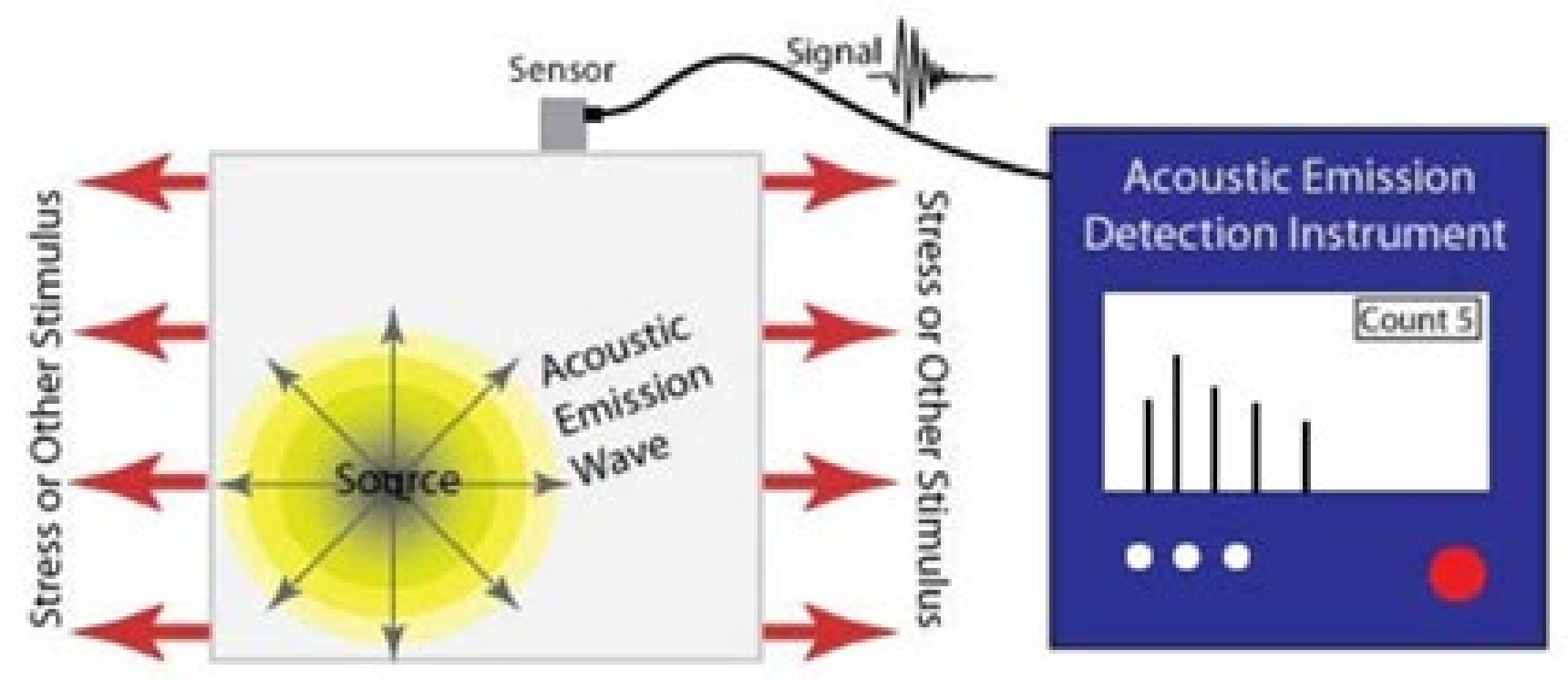
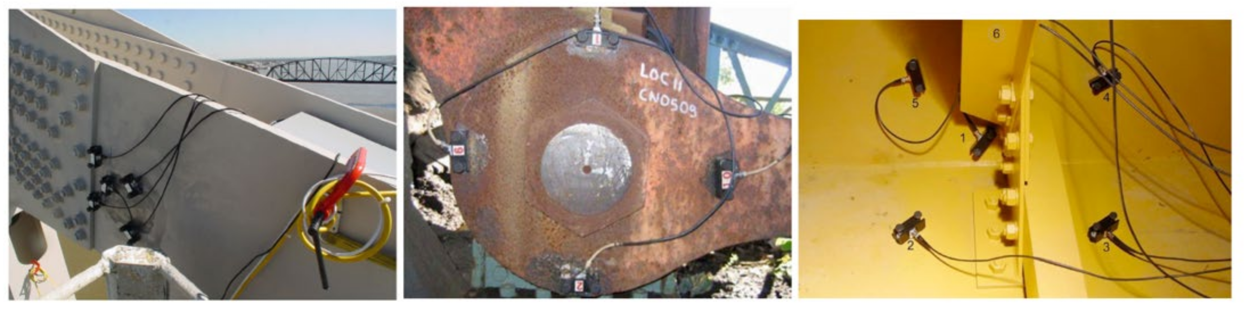
3.2.2. Acoustic Emission Testing (AE)

Another method that can be used for the NDT of steel bridges is Acoustic Emission Testing (AE). AE is implemented to monitor materials experiencing dynamic processes, including structural loading, corrosion, and weld heating and cooling.
The methodology of this technique works according to acoustic emissions generated as elastic waves (Figure 15) by the onset or progression of cracks and other discontinuities in steel elements. These waves are radiated outward from the vicinity of crack tips in a circular pattern and are sensed by the sensors (transducers) attached to the surface of the test piece seen by the AE monitor. Before the installation of the transducers, the coating should be removed at the attachment sites. In some cases, magnetic hold-downs are employed to couple the transducers to a test piece. For monitoring bridge components with the AE method, multiple transducers are typically used. To locate cracks and remove interference signals from noise sources, the transducers are to be placed on a test piece in geometric arrays. Figure 16 indicates the application of AE testing for the inspection of steel bridges [10].
The AE has various applications for steel bridge elements including for rolled shapes, plates, welded connections, pins, and cable fittings. This method can only be used to detect the onset of a defect or the progression of existing anomalies; it cannot be used to detect existing defects without major activity. The AE method has been used successfully for detecting wire breaks in cable-stayed bridges and fatigue cracking in orthotropic bridge decks [42]. It should be stated that this method requires special equipment and training for the inspectors.

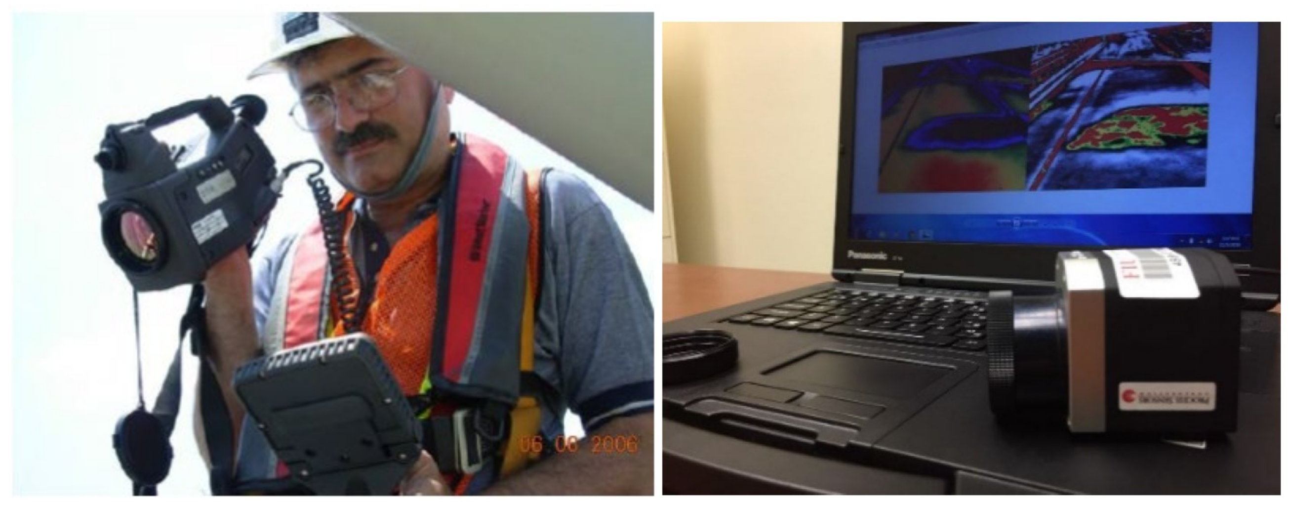
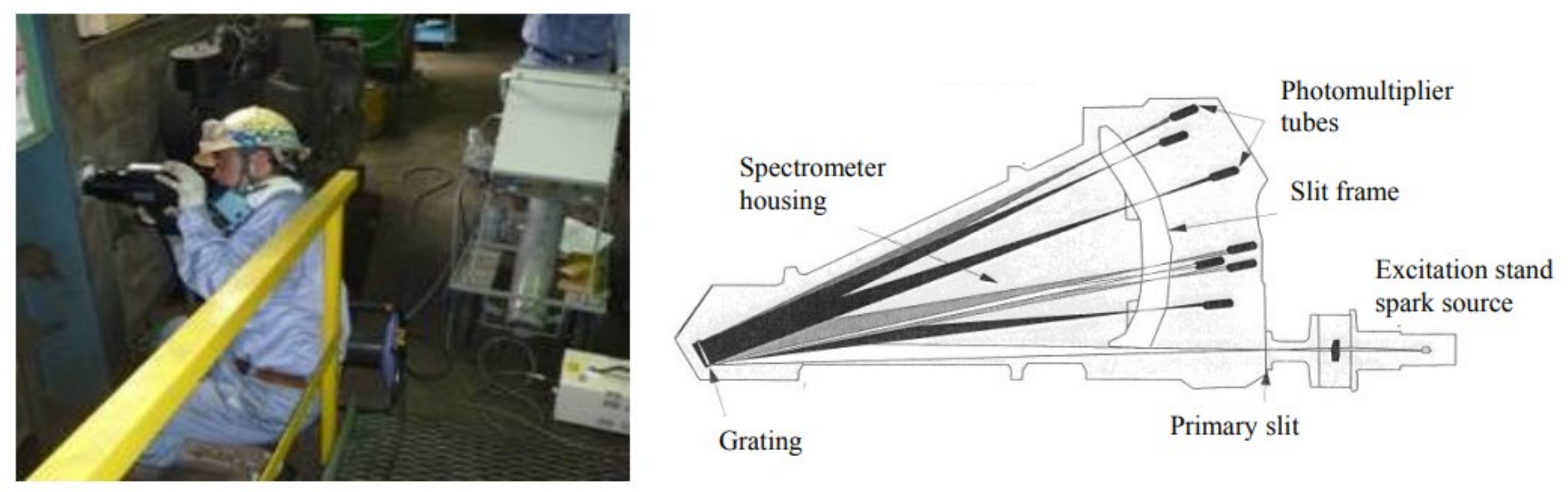
3.2.3. Infrared Thermography Testing (IT)

The IT method is based on the relationship between thermal radiation and temperature, where the heteromorphic structure of an object is described by the difference of the surface temperature distribution. In this technique, an infrared camera is implemented to measure the emitted infrared radiation from the test elements (Figure 17). Thus, by using different forms of active thermal excitation, the defect can be effectively detected. Figure 18 presents the principle of IT technology, where a heating source is applied to both a non-defected and defected object. If the material is uniform, i.e., without any defects, the thermal signal propagates smoothly through the object, while, for the defected object, the thermal signal results in sudden changes in the surface temperature distribution [43].
Much research has been carried out on the application of IT for steel elements [45,46,47]. Sakagami et al. [46] conducted an IT test on the steel deck of a steel bridge, with two types of cracks: Crack A (weld-bead-penetrant-type) and Crack B (through-deck-type), as shown in Figure 19 [46]. They found this technique practical for identifying the cracks. Mehrabi (2006) employed IT for the non-destructive evaluation of cables in cable-stayed bridges with an ambient heat source [44].
There are two types of IT technology, which include a traditional approach known as pulse thermography (PT) and the more advanced lock-in thermography (LT) [48]. The traditional PT uses a short-duration energy pulse and records the thermal response. In contrast, the LT uses mono-frequency sinusoidal thermal excitation to find the phase and magnitude of the reflected thermal wave from the recorded thermal images. The LT method provides better accuracy and efficiency for noise rejection, but it takes a considerably longer time to measure frequencies [48,49]. The PT method is known for its fast detection speed, large detection area, and ease of data access. This method can be implemented to detect cracks, rust, fatigue damage, and debonding in steel bridges [48,49,50].
According to the Non-destructive Evaluation Center of the Federal Highway Administration, compared to other NDT techniques, IT covers more areas for inspection, therefore it is a cost-effective method for inspection of steel bridges with large areas. Moreover, this method can indicate the percentage of deteriorated areas. However, there are some disadvantages to this technique, including the high cost of test equipment, being dependent on the proper temperature of the ambient, and the need for special training for the operators [51].

3.2.4. Radiographic Testing (RT)

This testing method uses X-rays or gamma rays to produce a radiograph of a specimen to register any changes in thickness, assembly details, and defects. Radiography has significant use in structural engineering, but for steel bridge inspection, more commonly, it is used for testing the welded joints. Cracks in welded joints under dynamic loading can propagate further and reduce the cross-section until the fracture of the welded part occurs. Although this type of NDT can be very slow and expensive, it has the capabilities and accuracy to detect porosity, cracks, inclusions, and defects in weld interiors. Figure 20 shows an inspection of a steel pipe and steel beam using the radiographic method [52]. Figure 21 shows an example of Radiographic Testing, where the defective specimen is subjected to a radiation source (either X-rays or gamma rays) [53].
The radiographic testing equipment consists of a radiation source, film cassette or digital flat panel detector, penetrometer, and filmmakers. Little or no surface preparation is needed for the application of RT. The most effective application for RT is for the detection of subsurface defects hidden from the naked eye. In this method, the test piece is subjected to the radiation source. Based on the material density, the radiation is transmitted at different rates and variations are captured on photographic film or fluorescent screen. Radiographic testing functions with an X-ray sensitivity of 2%, meaning that if the smallest dimension of a component is 20 mm, the smallest void that can be detected is 0.4 mm [15,54]. RT has also been used at an experimental level for detection of wire breaks in stay cables [55]. The disadvantages of the RT method for steel bridges include its slow operation and high cost, its serious safety issues and health hazards, its improper use for thick sections, and its need for expensive equipment and special training for the inspectors [56].

3.2.5. Laser Testing Method (LT)

Another NDT method that can be used for the detection of defects in steel bridges is the laser testing method. This method is in the experimental stage and information on its applicability is very limited. This method employs Lamb wave initiation by pulsed laser generating a laser impact on the component (Figure 22) [57]. The flaw is detected by a standing Lamb wave produced by the impact and recorded by the photorefractive interferometer. Guldur et al., in 2015, inspected and determined the condition ratings of a bridge component by employing quantified surface damage from a 3D laser image (point cloud image). They used two techniques for the inspection: Graph-based Surface Damage Detection and Surface Normal-based Surface Damage Detection. Graph-based Surface Damage Detection was implemented to detect the surface defect, including bent members, ruptures, and points of discontinuity; Surface Normal-based Surface Damage Detection was used to detect corrosion and cracks. It was concluded that the laser scanners could detect defects and flaws and can thus be employed to aid visual inspection [58,59].

3.3. Test Methods Applicable to Structural Steel Cables, Tendons, and Ropes

Structural tension elements normally pose additional challenges for their inspection and evaluation. For most of these elements, such as stay cables and post-tensioning tendons, the main steel tension elements are encased in protective sheathing and are filled by some type of corrosion inhibiting material. As such, they require methods with capabilities to penetrate beyond the protective elements. The methods discussed in this section are typically used for the inspection and damage detection of structural steel cables, tendons, and ropes in the bridges, but could be applicable to other components of steel bridges as well. Additionally, some of the above-mentioned methods, as stated in their description, can and have been used in the case of steel cables, tendons, and ropes, are not described in this section. These include Radiographic and Acoustic Emission Testing for detection of wire breaks along the cables, and Ultrasonic Testing for anchorage zones. Additionally, Infrared Thermography and Tap/Impact testing can be used to detect flaws in corrosion barriers [44].

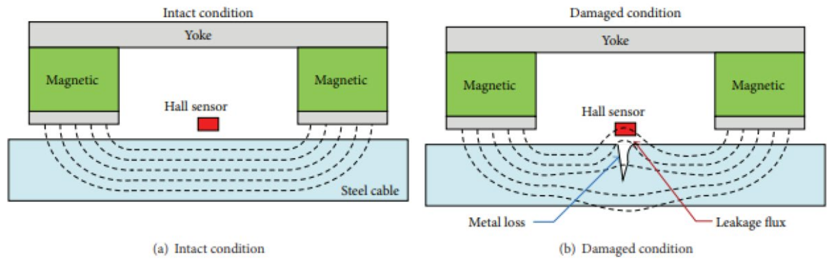
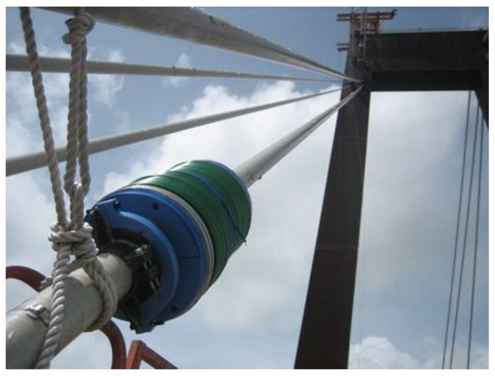
3.3.1. Magnetic Flux Leakage Testing (MFL)

In this method, to detect defects including corrosion, breaks, loss of cross-section, and pitting of steel components, the element is magnetized through the use of a strong external magnet [60]. The magnet source can be either a permanent or electrically activated magnet. In this method, the magnetic field is present between the probes of the magnet, so that a defect in the steel element leads to the leakage of the magnetic field in the material from its flux path [61]. The magnetic leakage is detected by magnetic sensors (e.g., a Hall sensor) placed between the magnet poles (Figure 23) [28]. The first reported use of this method for stay cables was the work by Bergamini in 2001 [62]. Figure 24 shows its application for I-310 Hale Boggs Bridge in Louisiana [10]. This technique has also been modified and implemented to inspect the stay cables of a bridge in Thailand (RAMA IX Bridge) [62].
MFL can also be implemented to detect flaws in bridge hanger cables and cables of cable cars with smaller diameters than stay cables. The equipment implemented for the MFL test for the stay cables includes a modular magnetizing and sensing unit mounted on the cable, and travels along the cable to detect flaws. The time for application of this testing method is 10–20 min per cable. However, the time typically is extended to 1 day per cable due to cable surface preparation and logistical matters. There are some limitations to this method, including safety considerations, because of the intense electromagnetic field, the need for heavy preparation of surface cable, and the heavy and expensive equipment [44].

3.3.2. Magnetostriction

The magnetostrictive sensor (MsS) technology was introduced at the Southwest Research Institute (SwRI) in the 1990s [63]. The concept for this technology is that the magnetic fields create small changes in the physical dimension of steel material, and material strains create changes in magnetization. Accordingly, when the magnetic field around the steel element is changed, an elastic wave is produced, traveling in both directions along the length of the wire. The stress wave modifies the magnetic induction of the material, so that it produces voltage in the receiving coil. This can be monitored and used for the detection of flaws. This method was used to inspect the hanger cables of the George Washington Bridge in New York City (Figure 25) [42].
This method was also implemented for the inspection of the anchorage area of main suspension cables. Their applications for stay cables are under investigation. The researchers concluded that this method is not practical for small defects and in the anchorage zones [42].

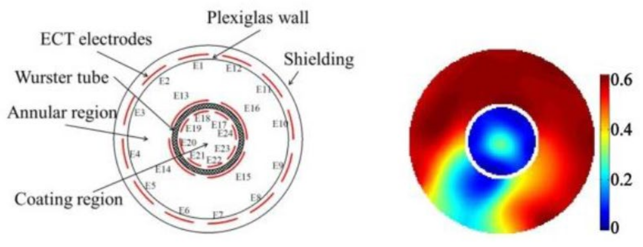
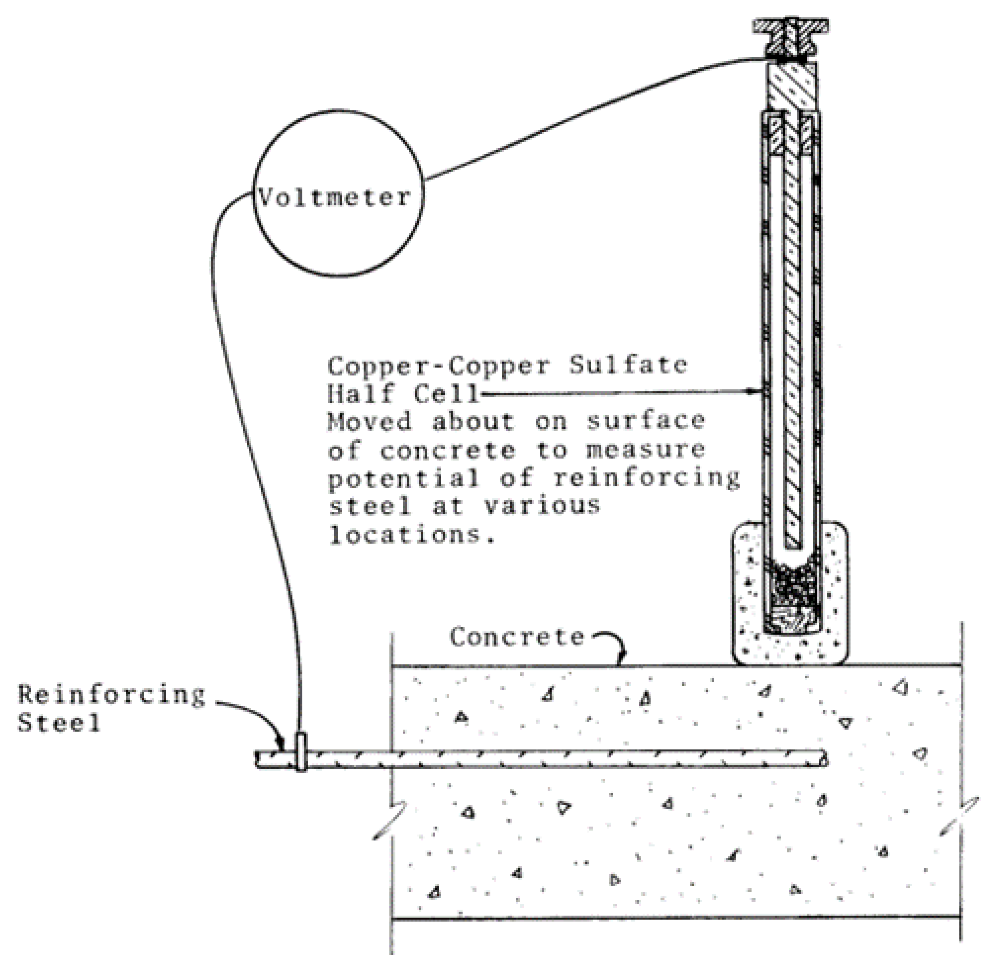
3.3.3. Chemical and Electrical Testing (CET)

CET is typically used for the detection of corrosion, voids, and inclusions of considerable sizes in the structural element. This NDT method can be categorized into:
Electrochemical Impedance Spectroscopy (EIS)—This is an impedance method in which a low-amplitude voltage (alternating current) is implemented to the steel under inspection over a wide range of frequencies. The changes in signal amplitude and phase shift can be measured to calculate the impedance of the concrete–steel interface. This method requires physical access to the element being inspected. The application of this method has been mostly for the external tendons. Special training and sophisticated approaches are needed for the interpretation of the data and extracting meaningful results [60]. This method is generally slow, as low frequencies are required to determine the corrosion rate. Its application has been mainly in laboratory conditions.
Electrical Capacitance Tomography (ECT)—This method was introduced in the late 1980s. ECT obtains capacitance data with the use of multi-electrode sensors and generates permittivity images of sections by several iterations (Figure 26). It is considered a fast, safe, and inexpensive NDT method. However, it has not been used widely, except in special investigations on small parts of structural elements. Its inherent problems with the image resolution are the major drawback for its application.
Chemical Testing (CT)—This method is mostly used to detect corrosion in the reinforced concrete elements but can be implemented for other structural elements. In the marine environment, the measurement of chloride in the element can be a means for detecting corrosion. This method for measuring chloride employs chemical testing or the use of sensors/indicators [64].
Another method of chemical testing has been investigated in the research conducted by Fujita and Masuda in 2014. The compositions of structural members were analyzed by wavelength through an optical emission spectrometer (Figure 27). In their work, the content of the chemical composition was analyzed by the strength on-site. Accordingly, weld crack sensitivity (Pcm) and carbon equivalent (Ceq) composition were evaluated by this method. These two components can be used for the detection of corrosion in the steel element [65]. The literature cited can be referenced for more details on procedures and applications.
Half-cell Potential Measurement, Galvanostatic Pulse Technique, and Potential Mapping—These methods are electrochemical techniques and have been used widely for corrosion detection in reinforced concrete elements, and, with some modifications, they can be used for stay cables and external post-tensioning tendons. The method requires a direct electrical connection to the steel element embedded in the grout/concrete and access to the face of the grout/concrete. The difference in potential between electrodes and electrolyte is utilized in a half-cell potential measurement technique. A schematic example is shown in Figure 28 [66]. Application of the half-cell potential method is inexpensive and simple to perform. Limitations exist when the grout/concrete is contaminated, leading to difficulties when obtaining quantitative measure for corrosion [67].
With a concept similar to half-cell potential measurement, the galvanostatic pulse method applies a current pulse to the steel embedded in grout/concrete, and polarizing potential is recorded after the pulse is turned off. In this way, the method attempts to eliminate the interference by concrete resistance, [68].
Using the above corrosion potential measurement methods, Corrosion Potential Mapping can be performed to obtain the distribution of corrosion in an area or length. This can be achieved either by point measurement in a coarse grid on the concrete surface or by semi-continuous measurement using wheeled equipment that are installed with multiple electrodes arranged to enable a small grid size. Potential mapping is easier on horizontal surfaces but can be adjusted to other conditions [67,69].

3.3.4. Vibration Method for Detecting Cross-Section Loss

The application of noncontact laser-based vibration technology for cable-stayed bridges has been on the rise over the years [44,70]. Although this technique was initially developed for stay-cabled bridges, it was adapted for other types of bridges. Dozens of major bridges in the US and abroad have implemented this technology for the inspection of their elements. This method was first introduced by Mehrabi and Tabatabai in 1998 [71], and its main usage was for the inspection of cables and tension elements in bridges. In this technique, by targeting the cable with the laser beam, cable vibration from ambient sources can be recorded from a distance. The cable vibration characteristics, including the frequencies and damping ratio, are calculated by analyzing the vibration record, and the force in cables is calculated. The estimated cable forces using this technique are then compared to the previously measured or expected forces to establish a pattern of changes indicating the type, intensity, and location of potential damages to the cable. The damping measured in this technique is used to determine their susceptibility to different types of wind-induced effects and other oscillations. Figure 29 indicates the laser vibrometer which targets cables and a sample comparison of the estimated forces [72].
The laser-based measurement technique provides a noncontact remote sensing ability. Accordingly, for a periodic inspection of the elements with a more difficult accessibility, the laser-based noncontact vibration technique can save a lot of on cost and time.
Other non-contact sensors have been used for vibration measurement. Non-contact microwave interferometric radars have also been used for the non-contact assessment of stay cables. This method can simultaneously measure the dynamic response of an array of stay-cables [73,74].
Vibration measurement can also be performed using contacting sensors. Accelerometers can be attached to the cables with proper clamps [42].

4. New and Developing Methods

This section reviews the new and developing NDT methods that can be implemented for the inspection of steel bridges.

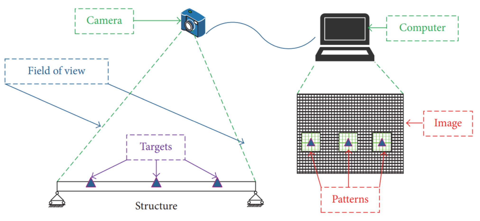
4.1. Vision-Based Inspection Methods

The application of vision-based methods for structural monitoring goes back decades. Some of the early uses of this technique was employed for the static and dynamic monitoring of bridges [75,76,77]. Many vision-based monitoring methods have been introduced to measure structural displacement, monitor vibration response and the stress/strain, and detect cracks and other anomalies with further processing [78,79,80]. Xu et al. (2018) performed a comprehensive review of vision-based structural health monitoring systems [81]. Their review has pointed out the growing use of vision-based methods for structural health monitoring for buildings and bridges [82,83,84,85]. They also proposed a simple vision-based method based on two major abilities: non-contacting and multi-point simultaneous sensing.
A vision-based measurement system typically includes an image acquisition device (digital camera, image grabber, and lens), image processing software, and a computer. In this technique, the image processing software plays an important role that is later integrated with the specific computational algorithm for obtaining the mechanical parameters in structural monitoring. Figure 30 indicates the methodology for this technique, in which the images consist of some predefined targets captured by the digital camera. By employing the digital image processing and pattern-matching algorithm, the targets are tracked, so that the displacement at the target positions on the structure is obtained. Accordingly, this method has great potential in detecting cracks and flaws in steel elements [86]. Vision-based methods are appropriate for measuring structural displacement, monitoring vibration response and stress/strain, and detecting cracks and other anomalies. These methods are not applicable to internal defects.

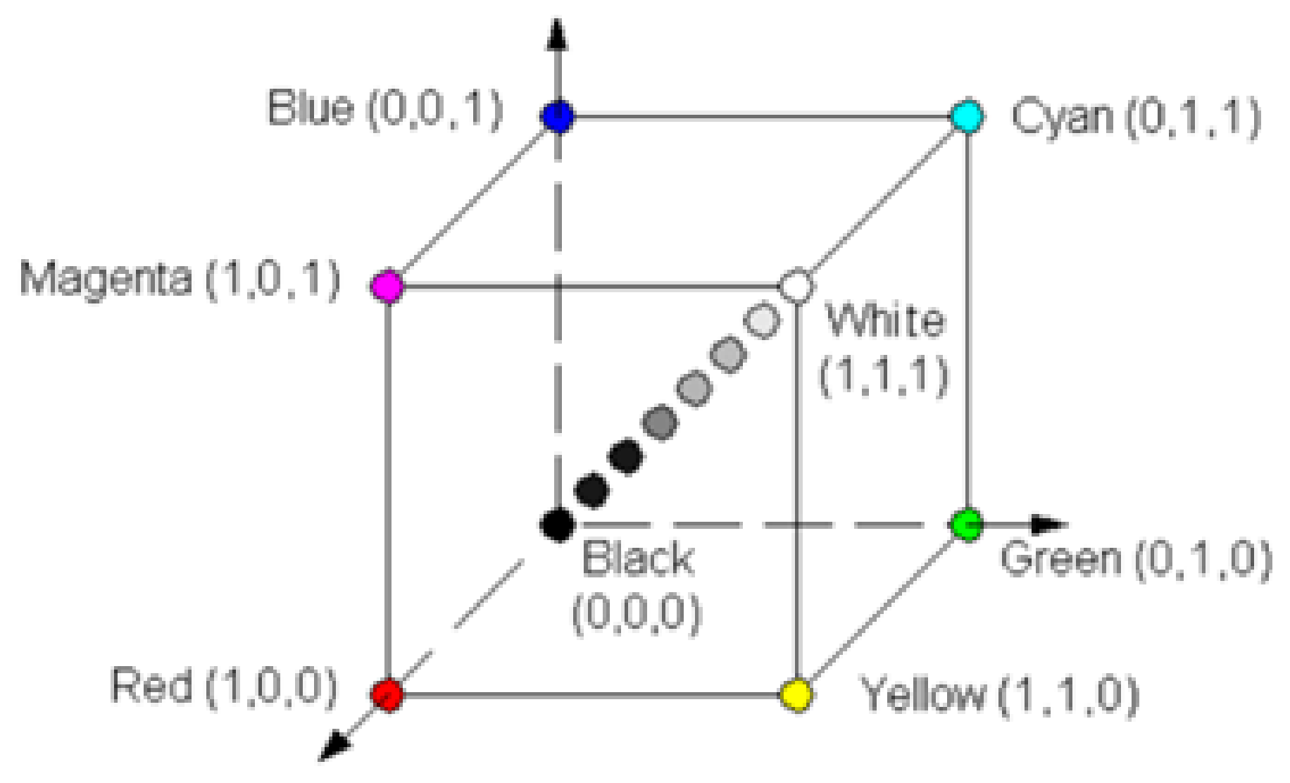
4.2. Digital Image Processing Method

The American Society for Testing and Materials (ASTM) [87] presents a guideline based on which an inspector shall be able to rate the corrosion for the inspected element. The key term for the measurement of the corrosion is the percentage of rusted surface, where a scale from 1 to 10 is incorporated (Table 1).
The digital image processing method entails an intelligent system that can automatically detect areas with rust through the processing of the captured photos. Digital image processing is not only limited to steel bridges, but can also be incorporated in other areas, including underground pipelines, construction material, and pavement, due to its accuracy, consistency, and objectivity. Lee and Chang [88,89] presented two different rust defect recognition methods. Both methods start with the same step of converting the original image to a grayscale image. After the conversion to grayscale, where the grayscale is expressed using light intensities from 0 to 255 (0 is black, and 255 is white), one of two recognition methods are applied: (1) Neuro-Fuzzy Recognition Approach (NFRA) [88,90]; (2) Simplified K-Means Approach (SKMA).
The ability to process digitized images can be obstructed due to different environmental conditions, low-contrast digital images, non-uniform illumination, and noises on painting surfaces. Unfavorable environmental and lighting conditions can lead to false indications since the lack of distinction exists between the rust pixels and the background. The unsatisfactory results are mainly due to the grayscale image processing. Lee and Chang [88] demonstrated that the implementation of color images for identifying the rust is feasible and more effective. The color space can be expressed as a 3D cube (Figure 31), representing the most fundamental color space with three primary colors, red, green, and blue (RGB).
Lee et al. [89] utilized color space for statistical data acquisition and multivariate statistical analysis to detect rust on steel bridges. Medeiros et al. [91] further developed color image processing by including image texture and color descriptions to fully describe the roughness and common color changes on metal surfaces. Shen et al. [92] used Fourier transform and texture features to model a Fourier Transform-based Defect Detection Approach (FT-DEDA) that is applicable to various environmental conditions. This method can process images of steel bridge coatings with various background colors, including brown and red colors that were not applicable for other similar methods. Another rust detection method known as RUDERM has been developed to address the limitation of the FT-DEDA method to distinguish rust from other types of defects. RUDERM incorporates the collected rust color spectrum in the RGB color space to develop a rust color range used to differentiate various types of defects. Figure 32 presents a comparison between the K-means method and RUDERM incorporated with K-means [92]. The comparison clearly shows that combining K-means and RUDERM methods results in a significantly higher accuracy than the use of K-means method alone in a shorter time.

5. Complementary to NDT Methods

Several techniques are implemented as complementary to NDT methods to improve monitoring efficiency and accuracy, to ease the inspection operations, and to reduce the cost associated with the inspection. These methods are described below.

5.1. Implementation of Robotic Technology

Due to the growing number of defective bridges affected by natural aging, corrosion, deterioration, loading conditions, etc., the need for inspections is rising, leading to a significant amount of cost and efforts [93,94]. The inspection of hard-to-reach locations also poses safety concerns for both the inspectors and the public (Figure 33). Other factors include traffic interruptions through lane closures and the need for specialized training for inspectors. Accordingly, the application of robotic technology is growing rapidly, for which only a limited amount of time is required to collect necessary data with a variety of sensors. The increased focus on robotics equipment, semi-autonomous or fully autonomous, for the NDE of bridge infrastructure, has led to the providing of previously inaccessible bridge areas with faster and more accurate inspections [95,96,97,98,99,100,101,102,103,104,105,106,107].
The automated robotic equipment must be a certain weight and size, implementing specific modes of operation, power supply, types of data collection, and accuracy [111], and, currently, not all NDT methods can be accommodated by robotic delivery. Depending on the area or component that needs to be inspected, there are three main types of inspection robots that are described below.

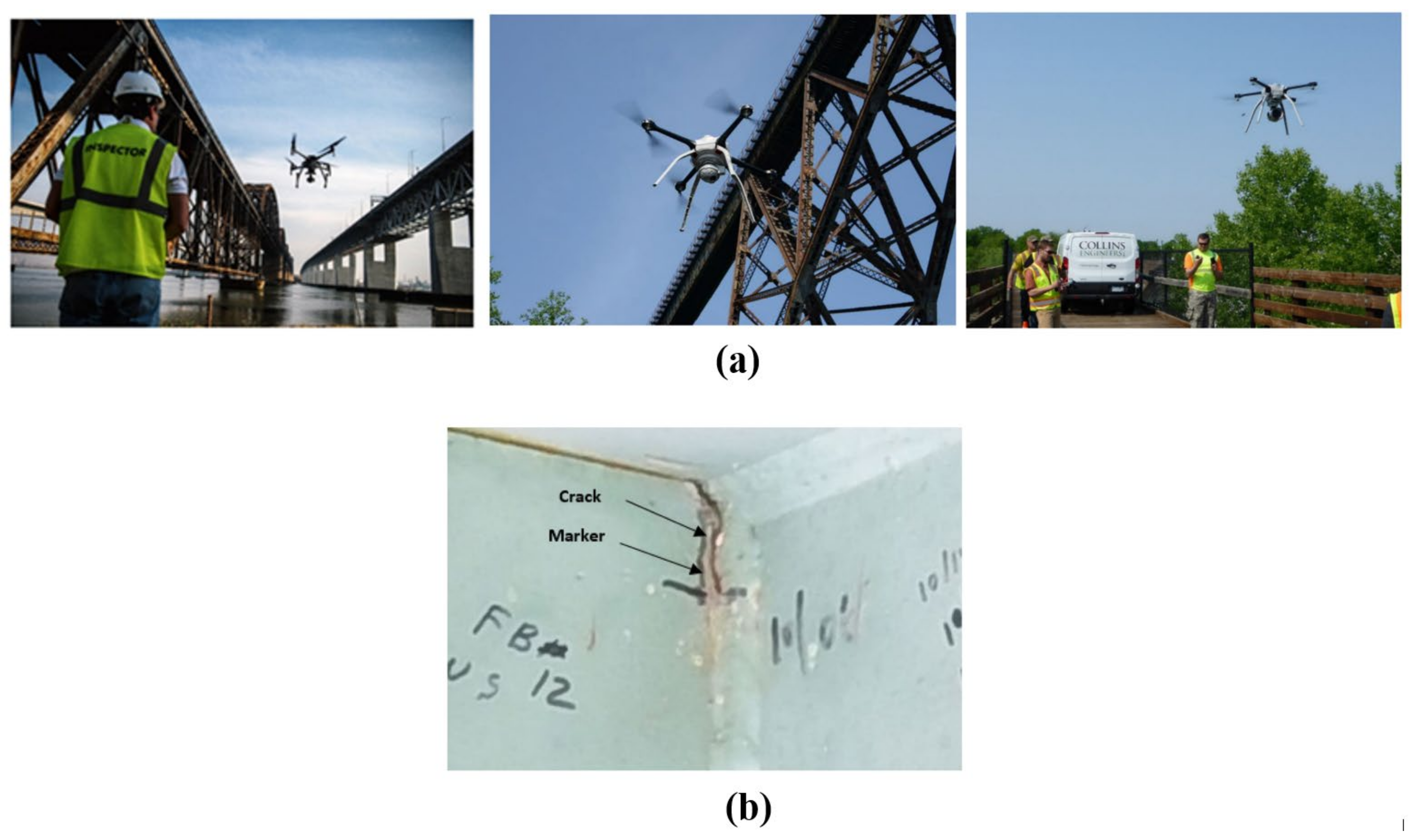
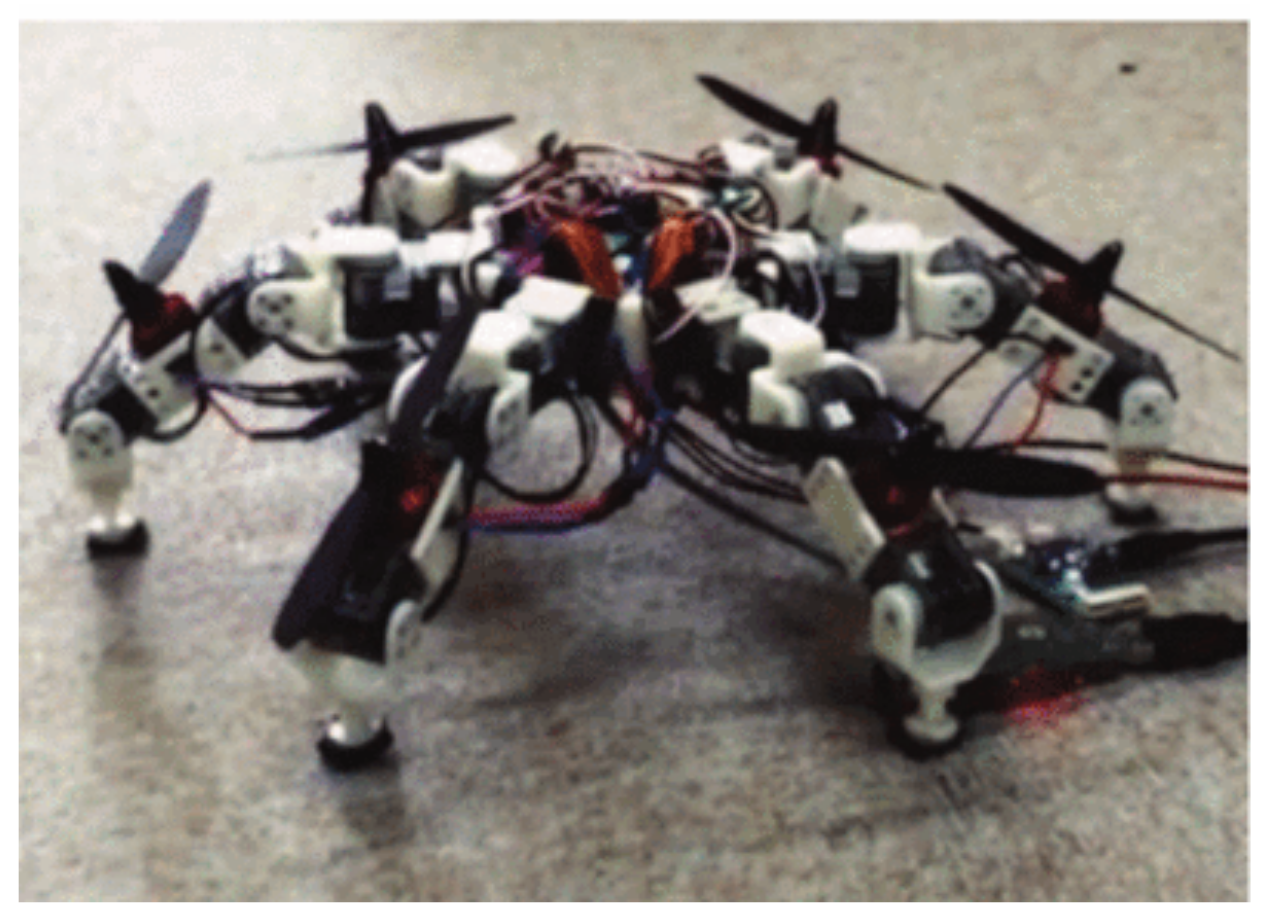
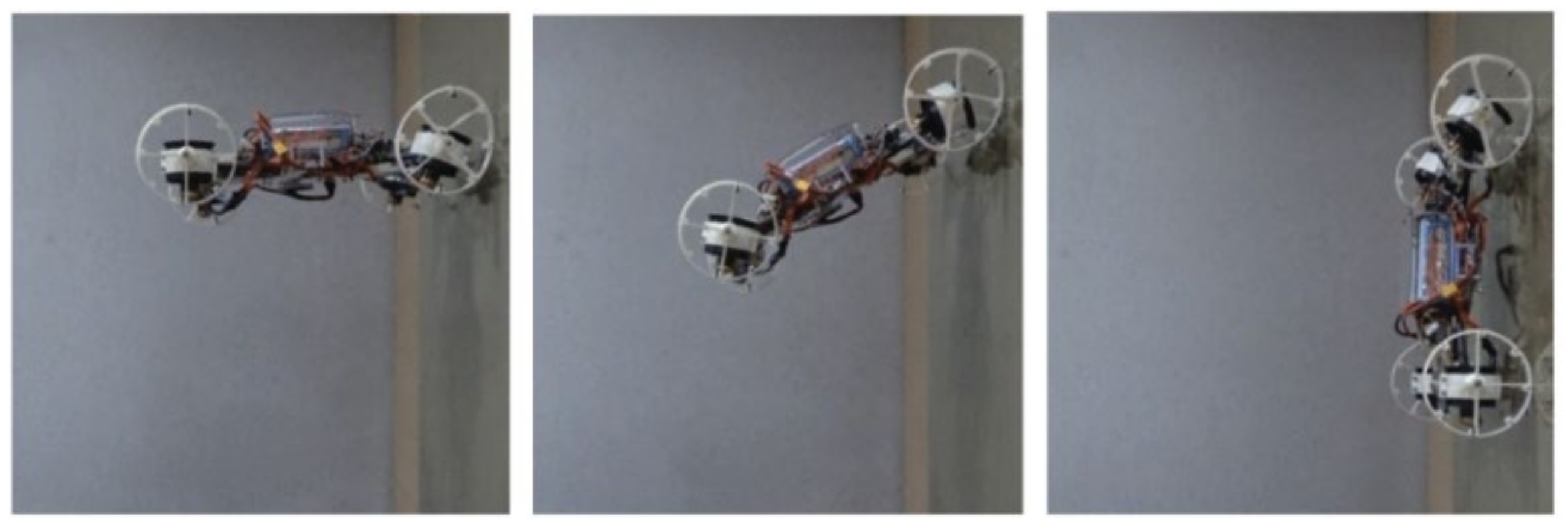
5.1.1. Aerial Robots

In the past decade, the use of aerial robotics, specifically Unmanned Aerial Vehicles (UAVs), or drones, have been emphasized in various fields, including mapping, surveillance, traffic control, inspections, and the health monitoring of bridges. They can reach areas inaccessible to humans or other ground vehicles and take off vertically, eliminating a need for a predetermined path of flight [112]. However, the inspection and health monitoring with the implementation of UAVs is still in the development stage, with more NDT methods being added gradually [113,114,115,116,117]. An example of aerial drone inspection can be seen in Figure 34.
There are also some limitations to this method, including the inability to remove any path obstructions, difficulty to fly during sustained gusts of winds and precipitation, battery life, network instability due to lack of GPS signal under the bridge, line of sight constraints, and the need for being close for crack detection [115,120]. The development of techniques such as image processing and machine learning can improve the limitations mentioned above [121]. Its advantages include a lower cost due to a lower number of personnel, not requiring lane closures, reduced inspection time, increased safety, and the ability to reach wider areas of the bridge [116,122].

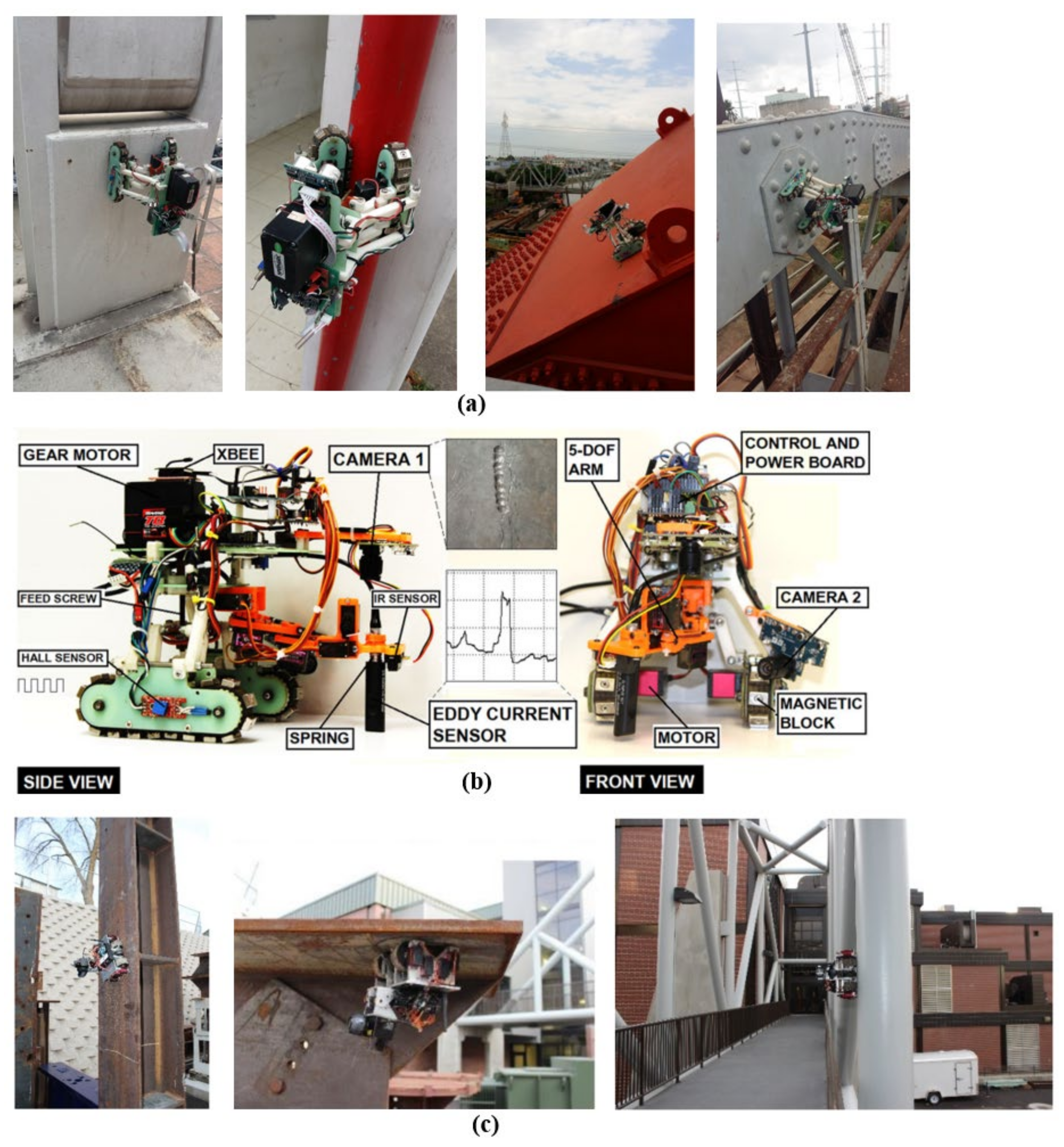
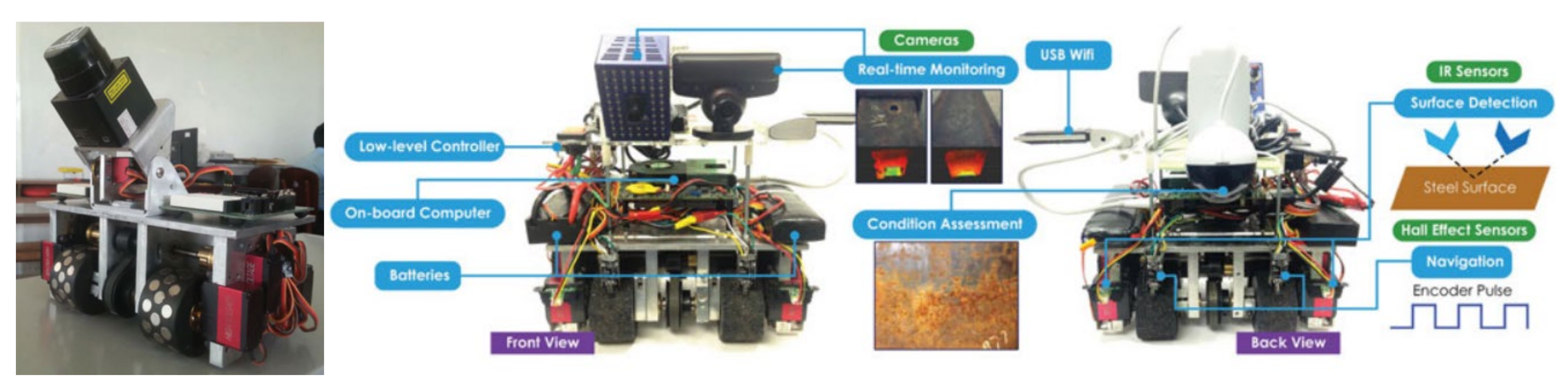
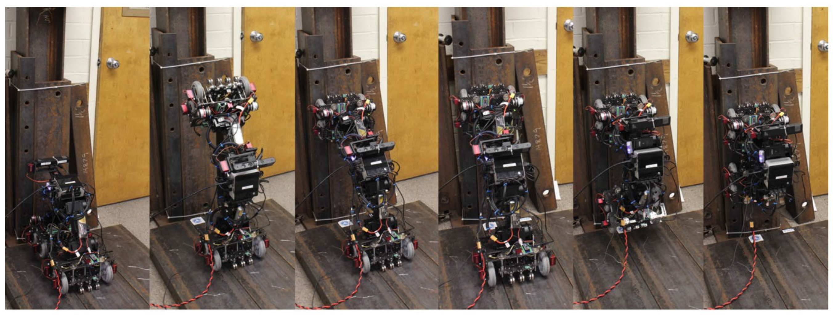
5.1.2. Ground Robots

Ground-based inspection robots represent the majority of the current advanced equipment used for the NDE and SHM of bridges. They can be further classified based on the type of locomotion they are implementing into a wheel-based robotic platform, climbing robotic platform, and bipedal as well as quadrupedal legged robotic platform [101,104,105,106,110,123,124,125,126,127]. Different types of ground and climbing robots can be adapted to handle different surfaces while still providing accurate navigation. Their mobility consisting of moving speed and traversing abilities should be taken into account for implementation. The pace of a ground inspection robot depends on the dimensions and areas of the structural element to be inspected. The traversing ability implies its steering and the capability to avoid any obstacles along its path, including internal and external corners, steps, welds, walls, or bolts. Furthermore, the battery life of the robotic platform should be considered when designing the path and required inspection areas due to the complexity of retrieving the robot after losing its power. Figure 35 presents several types of ground and climbing robots that can efficiently be used with NDT methods.
According to a review of robotic platforms in the NDE of civil engineering infrastructures [128], different sensors can be implemented with robotic systems. These sensors can be classified as radars (GPR sensors with EM waves of different wavelengths and frequencies), vision (visual representation with different types and quality of cameras), acoustic (sensors for sound with microphones, ultrasonic sensors, or different IE methods), and electric (sensors for variations in voltage and current, such as eddy current sensors). An example of a robotic system for the inspection of a steel bridge is shown in Figure 36. This climbing robot can move freely on a steel surface while carrying the sensors, collecting the data, and sending it to a ground station for processing [110].
Another example of the implementation of robotics with NDT methods is Automated Ultrasonic Testing (AUT). The effectiveness and accuracy of AUT systems have been investigated by several researchers for the detection of defects on steel components [129,130,131,132,133]. Figure 37 shows a prototype AUT system used for a steel plate and for the in-service bridge.

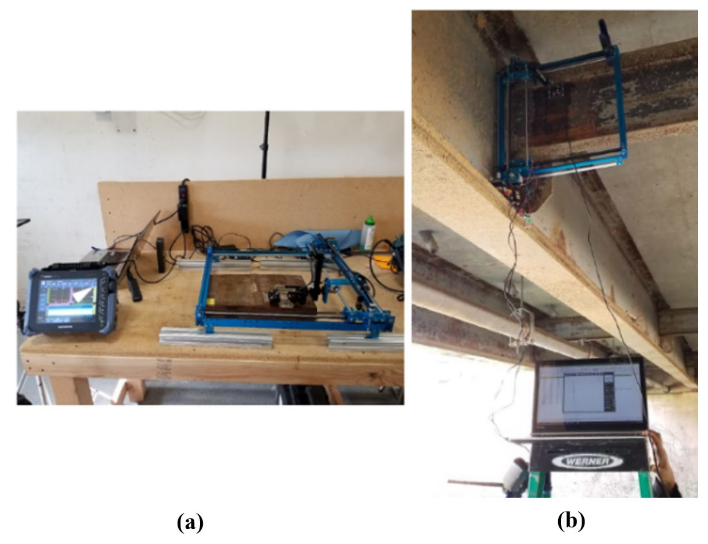
5.1.3. Hybrid Robots

Several research projects have studied hybrid inspection robotic equipment, investigating their ability to fly and walk for inspection purposes [99,107,134]. These special types of robots with advanced capabilities have been implemented to access different steel bridge components rapidly. Figure 38 shows the hybrid robot prototype, which was designed for efficient maneuvering in 3D dimensions. Myeong and Myung [134] presented a wall-climbing robot based on a drone platform called the Climbing Aerial Robot System (CAROS). This robotic system generates friction force using normal force to the wall, which enables its movement on different wall conditions with the use of novel tiltrotors, as shown in Figure 39. Figure 40 shows a new hybrid robotic system to inspect steel bridges developed by Bui et al. This system has capabilities that entail mobile and inch-worm transformation, implementing autonomous real-time navigation for minimizing human involvement [107].
To sum up, innovative robotic systems provide various functions and maneuvering capabilities, but they still require extensive research on their stability when moving in 3D space. Future research is needed to improve their performance to avoid sudden failure and damage, to ease their application in the field and testing, and to increase their accuracy.

5.2. Global Structural Response Testing (GSR)

The global structural response testing can also be considered a complementary NDT method for monitoring steel bridges. For example, vibration and modal techniques are implemented for evaluating the condition of elements through the mechanical properties reflected in their dynamic behavior. Defects in the structures affect the structural responses, including modal frequencies and modal shapes. As such, any change in the structural response can be a symptom of a defect. It should be noted that global techniques are applicable where the structural damage is significant, as the modal parameters are not sufficiently sensitive to identify minor structural damage and their locations [28,135]. The following discusses the application of the vibration method for the detection of fractures in steel bridges.
Damage detection through the determination of changes in the dynamic characteristics is one of the most widely used global response methods [136,137]. The source of excitation for vibration testing can be ambient (traffic or wind) or manual (loading and shakers). Abedin and Mehrabi [138,139] have developed a laser-based noncontact vibration technique for continuous or periodic bridge monitoring and damage detection through the changes in the natural frequencies of a bridge to address cost, traffic interruption, and safety issues associated with conventional bridge vibration monitoring. In this technique, a laser vibrometer is used to capture the bridge vibration under normal operation without interruption to traffic and without the need for direct access to the bridge. The results can be compared to measurements in previous period or finite element analysis for the indication of damage if a certain threshold is surpassed. The feasibility of using self-powered wireless sensors for monitoring steel bridges has also been investigated [140]. Abedin and Mehrabi (2021) studied the modal analysis method and demonstrated its applicability for damage detection in steel girder bridges. Their results showed that modal sensitivities are indicative enough for detecting certain expected damages in simple and continuous span bridges, where the frequency change method may not be adequately sensitive [141].
Based on the above review, Table 2 and Table 3 are developed, summarizing the applications, advantages, and disadvantages of various NDT methods for the inspection of steel bridges.

6. Summary and Conclusions

This study investigated non-destructive testing (NDT) methods used for the inspection of steel bridges with a focus on methods applicable to local damage detection. Their applications, advantages, and disadvantages were discussed and tabulated. This study also reviewed ongoing research studies regarding the implementing of the robotic technologies for the structural health monitoring and inspection of steel bridges. The following conclusions can be made from this study:
  • NDT methods are used to detect and characterize any flaws in the steel components with no or minimal damage to the member.
  • Among all NDT techniques, visual inspection is the least costly and easiest method. However, because visual inspection depends strongly on the level of experience and expertise of the inspector, the results are subjective, and different results might be obtained when different inspectors are involved. Accordingly, when potential for critical damage exists, other techniques should be used in conjunction with this method to assure valuable results. Use of visual aids as well as vision-based techniques with digital processing can increase the accuracy and reliability of inspection results.
  • NDT methods are normally categorized based on their ability to detect internal defects or external defects, having in mind that some methods can detect defects both on and beneath the surface. Considering the type of steel elements, the type and location of damages, and the capability of NDT methods in detecting the internal and external defects, testing methods applicable to steel bridges were categorized and discussed in this paper.
  • Visual inspection, dye penetrant, magnetic particle, and eddy current are NDT methods applicable to only surface defects. Visual inspection is the most common and appropriate NDT method for detecting noticeable flaws, which is used for the majority of steel bridges. The dye penetrant method is a practical way for the detection of flaws in non-porous surfaces. Magnetic particle testing is a fast and inexpensive NDT method suitable for ferromagnetic materials that requires minimum training for inspectors. The eddy current method is a rapid inspection technique that can be implemented with automation. This method can also be used for the detection of flaws for surfaces with conductive and non-conductive coatings requiring little or no surface preparation.
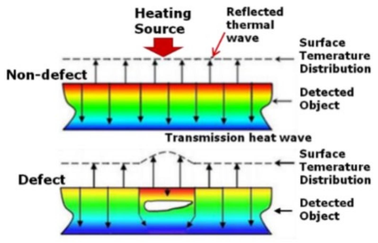
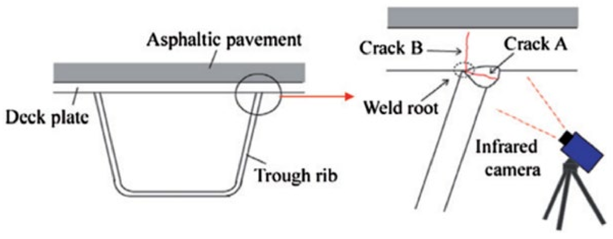
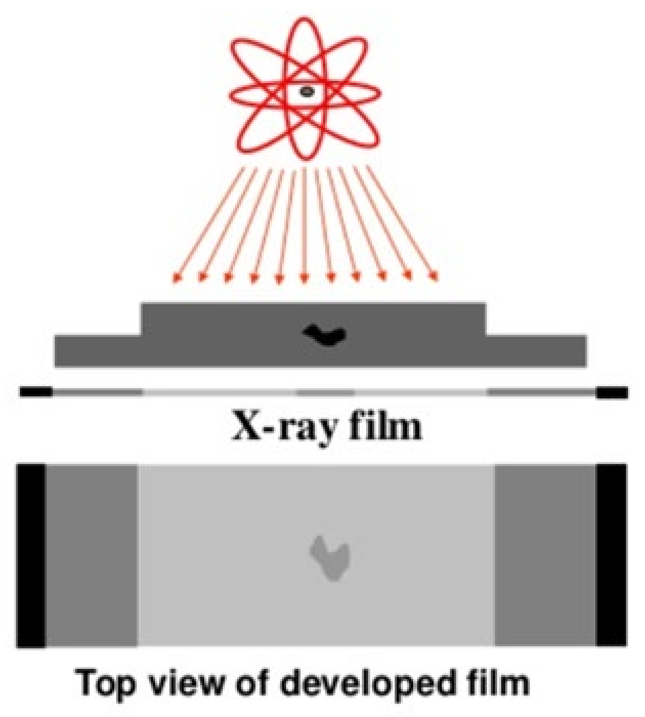
  • Acoustic Emission Testing, Infrared Thermography Testing, Ultrasonic Testing, radiographic testing, and laser testing methods are normally used for the detection of subsurface or internal defects in steel bridges, but they can be implemented for the detection of surface damages as well. Care should be taken with radiographic testing methods, as the radiation can pose a health hazard. Despite its slow and costly process, it can detect porosity, cracks, and inclusions in weld interiors with a high accuracy. The Ultrasonic Testing method is practical for the detection of subsurface volumetric flaws. It is very sensitive and accurate but requires relatively expensive equipment. The infrared thermography is cost-effective for the inspection of steel bridges with large areas. However, it cannot be implemented to accurately inspect thick components. Acoustic Emission Testing is a suitable method for the detection of active and incipient cracks, but it cannot be implemented to detect existing inactive defects.
  • For structural tension elements such as cables, tendons, and ropes, certain NDT methods are more common. These include Magnetic Flux Leakage Testing, Chemical and Electrical Testing, Chemical and Electrical Testing, Radiographic Testing (RT), and Acoustic Emission Testing. Ultrasonic Testing can be used for the detection of wire cross-section losses in the anchorage zones, and infrared thermography and Tap/Impact testing can be employed to detect defects in corrosion barriers. The non-contact and contact vibration method is another NDT method that can indirectly indicate flaws in cables and tension elements. The advantage of this method is its ability to detect flaws without being in a close vicinity of the component, and normally does not cause any interruption to traffic.
  • The implementation of robotics technology for NDT of steel bridges has improved the reliability and accuracy of testing, reduced the cost and time of inspection, and eased the process significantly.
This paper has also reviewed novel approaches for the non-destructive evaluation of steel bridges, including a vision-based monitoring method, along with a digital image processing and non-contact sensor method. It is expected that this compilation will help practitioners determine the selection and application of the most appropriate NDT methods, and will assist researchers in their path for developing new and improved methods.

Author Contributions

Conceptualization, S.S.K.D. (Seyed Saman Khedmatgozar Dolati), N.C., A.M. and S.S.K.D. (Seyed Sasan Khedmatgozar Dolati); methodology, S.S.K.D. (Seyed Saman Khedmatgozar Dolati), N.C., S.S.K.D. (Seyed Sasan Khedmatgozar Dolati), and A.M.; software, S.S.K.D. (Seyed Saman Khedmatgozar Dolati); formal analysis, S.S.K.D. (Seyed Saman Khedmatgozar Dolati), N.C., A.M. and S.S.K.D. (Seyed Sasan Khedmatgozar Dolati); investigation, S.S.K.D. (Seyed Saman Khedmatgozar Dolati), N.C., A.M. and S.S.K.D. (Seyed Sasan Khedmatgozar Dolati); resources, S.S.K.D. (Seyed Saman Khedmatgozar Dolati), N.C. and A.M.; data curation, S.S.K.D. (Seyed Saman Khedmatgozar Dolati) and A.M.; writing—original draft preparation, S.S.K.D. (Seyed Saman Khedmatgozar Dolati), N.C., A.M. and S.S.K.D. (Seyed Sasan Khedmatgozar Dolati); writing—review and editing, S.S.K.D. (Seyed Saman Khedmatgozar Dolati) and A.M.; visualization, S.S.K.D. (Seyed Saman Khedmatgozar Dolati), N.C., S.S.K.D. (Seyed Sasan Khedmatgozar Dolati), and A.M.; supervision, A.M. All authors have read and agreed to the published version of the manuscript.

Funding

This research received no external funding.

Data Availability Statement

The data presented in this study are available on request from the corresponding author.

Acknowledgments

The authors greatly acknowledge the internal support by the Department of Civil and Environmental Engineering at Florida International University. The contents of this paper reflect the views of the authors, who are responsible for the facts and the accuracy of the information presented herein.

Conflicts of Interest

The authors declare that they have no known competing financial interest or personal relationships that could have appeared to influence the work reported in this paper.

References

  1. Structurally Deficient Bridges|Bridge Infrastructure|ASCE’s 2021 Infrastructure Report Card. Available online: https://infrastructurereportcard.org/cat-item/bridges/ (accessed on 23 May 2021).
  2. Highways and Bridges—NACE. Available online: https://www.nace.org/resources/industries-nace-serves/highways-bridges (accessed on 23 May 2021).
  3. FHWA—FAPG 23 CFR 650C, National Bridge Inspection Standards. 2004. Available online: https://www.fhwa.dot.gov/legsregs/directives/fapg/cfr0650c.htm (accessed on 23 May 2021).
  4. Rus, G. Nondestructive Evaluation Laboratory 2010. U.S. Department of Transportation, Federal Highway Administration. 2010. Available online: https://highways.dot.gov/research/laboratories/nondestructive-evaluation-laboratory/nondestructive-evaluation-laboratory-overview (accessed on 23 May 2021).
  5. Dolati, S.S.K.; Mehrabi, A. Review of available systems and materials for splicing prestressed-precast concrete piles. Structures 2021, 30, 850–865. [Google Scholar] [CrossRef]
  6. Mehrabi, A.B.; Khedmatgozar Dolati, S.S. Alternative Materials and Configurations for Prestressed-Precast Concrete Pile Splice Connection; ABC-UTC Rep.; Accelerated Bridge Construction University Transportation Center (ABC-UTC): Miami, FL, USA, 2020. [Google Scholar]
  7. Corrosion of Steel—Reliant Institute of Technology. 2018. Available online: http://www.relianttechnologyinstitute.com/blog/tekla/corrosion-of-steel/ (accessed on 23 May 2021).
  8. Dogan, M. Delamination failure of steel single angle sections. Eng. Fail. Anal. 2011, 18, 1800–1807. [Google Scholar] [CrossRef]
  9. Haghani, R.; Al-Emrani, M.; Heshmati, M. Fatigue-prone details in steel bridges. Buildings 2012, 2, 456–476. [Google Scholar] [CrossRef]
  10. Hopwood, T.; Gof, C.; Fairchild, J.; Palle, S. Nondestructive Evaluation of Steel Bridges: Methods and Applications; Kentucky Transportation Center, University of Kentucky: Lexington, KY, USA, 2016. [Google Scholar]
  11. Phares, B.M.; Rolander, D.D.; Graybeal, B.A.; Washer, G.A. Reliability of visual bridge inspection. Public Roads 2001, 64, 22–29. [Google Scholar]
  12. Campbell, L.E.; Connor, R.J.; Whitehead, J.M.; Washer, G.A. Benchmark for Evaluating Performance in Visual Inspection of Fatigue Cracking in Steel Bridges. J. Bridg. Eng. 2020, 25, 04019128. [Google Scholar] [CrossRef]
  13. Dye Penetrant Testing (PT)—Nondestructive Evaluation (NDE) Web Manual. Federal Highway of Administration Research and Technology. 2015. Available online: https://cms7.fhwa.dot.gov/research/projects/nondestructive-evaluation-nde-web-manual (accessed on 28 September 2021).
  14. Achille Peiris, B.S. Capillary Action—Chemistry LibreTexts; LibreTexts: Davis, CA, USA, 2017. [Google Scholar]
  15. Dwivedi, S.K.; Vishwakarma, M.; Soni, A. Advances and researches on non destructive testing: A review. Mater. Today Proc. 2018, 5, 3690–3698. [Google Scholar] [CrossRef]
  16. FMB Oxford Non Destructive Testing—Dye Penetrant Inspection. Ionisation Chambers. Available online: http://www.wermac.org/others/ndt_dyepenetrant.html (accessed on 28 May 2021).
  17. Worman, J. Liquid Penetrant Examination. 2011. Available online: http://www.nationalboard.org/index.aspx?pageID=164&ID=374 (accessed on 29 May 2021).
  18. Willcox, M.; Downes, G. A Brief Description of NDT Techniques; Toronto NDT Equip. Ltd.: Bedford, VA, USA, 2003. [Google Scholar]
  19. Magnetic Particle Inspection, Inspection Services. Available online: http://ccindt.com/magnetic-particle-inspection.php (accessed on 28 September 2021).
  20. Globetrace Magnetic Particle Inspection (MPI). Available online: http://www.globetrace.co.uk/?page_id=96 (accessed on 30 May 2021).
  21. Simionescu, D.; Mitelea, I.; Karancsi, O.; Utu, I.-D. Research on the nondestructive examination of narrow gap MAG welding of API 5L X65M thermomechanical treated steel. Mater. Today Proc. 2021, 45, 4105–4111. [Google Scholar] [CrossRef]
  22. Eddy Current Testing|Institut Dr; Foerster GmbH und Co., KG. Available online: http://www.foerstergroup.com/en/usa/technology/eddy-current-testing/ (accessed on 29 May 2021).
  23. Sophian, A.; Tian, G.; Fan, M. Pulsed Eddy Current Non-destructive Testing and Evaluation: A Review. Chinese J. Mech. Eng. 2017, 30, 500–514. [Google Scholar] [CrossRef] [Green Version]
  24. García-Martín, J.; Gómez-Gil, J.; Vázquez-Sánchez, E. Non-destructive techniques based on eddy current testing. Sensors 2011, 11, 2525–2565. [Google Scholar] [CrossRef] [Green Version]
  25. Lamtenzan, D.; Washer, G.; Lozev, M. Detection and Sizing of Cracks in Structural Steel Using the Eddy Current Method; FHWA-RD-00; Turner-Fairbank Highway Research Center: McLean, VA, USA, 2000. [Google Scholar]
  26. Hellier, C.J. Handbook of Nondestructive Evaluation; McGraw-Hill Education: New York, NY, USA, 2013; ISBN 0071777148. [Google Scholar]
  27. Shokouhi, P.; Wolf, J.; Wiggenhauser, H. Detection of delamination in concrete bridge decks by joint amplitude and phase analysis of ultrasonic array measurements. J. Bridge Eng. 2014, 19, 4013005. [Google Scholar] [CrossRef]
  28. Farhangdoust, S.; Mehrabi, A. Health monitoring of closure joints in accelerated bridge construction: A review of non-destructive testing application. J. Adv. Concr. Technol. 2019, 17, 381–404. [Google Scholar] [CrossRef] [Green Version]
  29. Mohamed, O.A.; Rens, K.L. Ultrasonic testing of properties of 50 year old concrete. Mater. Eval. 2001, 59, 1426–1430. [Google Scholar]
  30. Ongpeng, J.M.C.; Oreta, A.W.C.; Hirose, S. Contact and noncontact ultrasonic nondestructive test in reinforced concrete beam. Adv. Civ. Eng. 2018, 2018, 1–10. [Google Scholar] [CrossRef]
  31. Mehrabi, A.; Farhangdoust, S. NDT Methods Applicable to Health Monitoring of ABC Closure Joints; Accelerated Bridge Construction University Transportation Center (ABC-UTC): Miami FL, USA, 2019. [Google Scholar]
  32. Dube, N. Introduction to Phased Array Ultrasonic Technology Applications, 4th ed.; Olympus Technical Communications Service, Ed.; Olymous: Waltham, MA, USA, 2004. [Google Scholar]
  33. Lin, Z.B.; Azarmi, F.; Al-Kaseasbeh, Q.; Azimi, M.; Yan, F. Advanced Ultrasonic Testing Technologies with Applications to Evaluation of Steel Bridge Welding—An Overview. Appl. Mech. Mater. 2015, 727–728, 785–789. [Google Scholar] [CrossRef]
  34. Phased Array Services—Acuren. Available online: https://www.acuren.com/inspection/advanced-nde-ndt/phased-array/ (accessed on 29 May 2021).
  35. Sinclair, A.N.; Fortin, J.; Shakibi, B.; Honarvar, F.; Jastrzebski, M.; Moles, M.D.C. Enhancement of ultrasonic images for sizing of defects by time-of-flight diffraction. NDT E Int. 2010, 43, 258–264. [Google Scholar] [CrossRef]
  36. Time-of-Flight Diffraction (TOFD) vs Phased Array Methods: What’s the Difference?|Zetec. Available online: https://www.zetec.com/blog/time-of-flight-diffraction-tofd-vs-phased-array-methods-whats-the-difference/ (accessed on 29 May 2021).
  37. Baskaran, G.; Balasubramaniam, K.; Lakshmana Rao, C. Shear-wave time of flight diffraction (S-TOFD) technique. NDT E Int. 2006, 39, 458–467. [Google Scholar] [CrossRef]
  38. TOFD—AUT Solutions. Available online: https://autsolutions.net/ndt-resources/tofd/ (accessed on 29 May 2021).
  39. Laprise, F.; Berlanger, J.; Maes, G. Sectorial Scan PAUT Combined with TOFD, a Robust Weld Inspection Technique in Lieu of RT. In Proceedings of the 18th Conference on Nondestructive Testing, Durban, South Africa, 16–20 April 2012. [Google Scholar]
  40. Hay, D.R.; Cavaco, J.A.; Mustafa, V. Monitoring the civil infrastructure with acoustic emission: Bridge case studies. J. Acoust. Emiss. 2009, 27. [Google Scholar]
  41. Kosnik, D.E.; Marron, D.R. Acoustic Emission Evaluation of Retrofits on the I-80 Bryte Bend Bridge, Sacramento, California. In Proceedings of the AEWG-50/ICAE-6. Acoustic Emission Working Group, CO, USA, and Acoustic Emission Group, Encino, CA, USA, Lake Tahoe, NV, USA, 29 October–2 November 2007. [Google Scholar]
  42. Tabatabai, H. Inspection and Maintenance of Bridge Stay Cable Systems: A Synthesis of Highway Practice; Transportation Research Board: Washington, DC, USA, 2005; Volume 353, ISBN 0309097606. [Google Scholar]
  43. Qu, Z.; Jiang, P.; Zhang, W. Development and application of infrared thermography non-destructive testing techniques. Sensors 2020, 20, 3851. [Google Scholar] [CrossRef]
  44. Mehrabi, A.B. In-service evaluation of cable-stayed bridges, overview of available methods and findings. J. Bridge Eng. 2006, 11, 716–724. [Google Scholar] [CrossRef]
  45. Díaz, F.A.; Patterson, E.A.; Tomlinson, R.A.; Yates, J.R. Measuring stress intensity factors during fatigue crack growth using thermoelasticity. Fatigue Fract. Eng. Mater. Struct. 2004, 27, 571–583. [Google Scholar] [CrossRef]
  46. Sakagami, T.; Izumi, Y.; Kubo, S. Application of infrared thermography to structural integrity evaluation of steel bridges. In Proceedings of the Journal of Modern Optics; Taylor & Francis Group: London, UK, 2010; Volume 57, pp. 1738–1746. [Google Scholar]
  47. Izumi, Y.; Sakagami, T.; Kubo, S. Stress Intensity Factor Measurements for Fatigue Cracks in Steel Bridges Based on Thermoelastic Stress Analysis. In Proceedings of the 12th International Conference on Fracture 2009 (ICF-12), Ottawa, ON, Canada, 12–17 July 2009. [Google Scholar]
  48. Tuli, S.; Mulaveesala, R. Defect detection by pulse compression in frequency modulated thermal wave imaging. Quant. Infrared Thermogr. J. 2005, 2, 41–54. [Google Scholar] [CrossRef]
  49. Maldague, X.; Galmiche, F.; Ziadi, A. Advances in pulsed phase thermography. Infrared Phys. Technol. 2002, 43, 175–181. [Google Scholar] [CrossRef] [Green Version]
  50. Rodríguez-Martín, M.; Lagüela, S.; González-Aguilera, D.; Martinez, J. Prediction of depth model for cracks in steel using infrared thermography. Infrared Phys. Technol. 2015, 71, 492–500. [Google Scholar] [CrossRef]
  51. Wimsatt, A.J.; Scullion, T.; Fernando, E.G.; Hurlebaus, S.; Lytton, R.L.; Zollinger, D.G.; Walker, R.S. A Plan for Developing High-Speed, Nondestructive Testing Procedures for Both Design Evaluation and Construction Inspection; TRB: Washington, DC, USA, 2009. [Google Scholar]
  52. Gamma Radiography (RT). Available online: https://www.shawcor.com/integrity-management-solutions/ndt-and-inspection-services/onshore-inspection-services/gamma-radiography-(rt) (accessed on 28 May 2021).
  53. Sukesh, O.P. Radiographic Testing (RT)-NDT. Available online: https://www.slideshare.net/SukeshOP/ndt-module-5 (accessed on 28 May 2021).
  54. Kumar, S.; Mahto, D. Recent Trends in Industrial and Other Engineering Applications of Non Destructive Testing: A ReviewNo Title. Int. J. Sci. Eng. Res. 2013, 4, 13. [Google Scholar]
  55. De Pinna, M.A. Focus: Applications of high energy X-ray inspection of post-tensioned concrete structures and cable stay bridges. PTI J. 2003, 1, 43–48. [Google Scholar]
  56. Wilkinson, S.; Duke, S.M. Comparative Testing of Radiographic Testing, Ultrasonic Testing and Phased Array Advanced Ultrasonic Testing Non Destructive Testing Techniques in Accordance with the AWS D1.5 Bridge Welding Code; Florida Department of Transportation: Tallahassee, FL, USA, 2014; p. 38.
  57. Lee, S.; Kalos, N. Non-destructive testing methods in the US for bridge inspection and maintenance. KSCE J. Civ. Eng. 2014, 18, 1322–1331. [Google Scholar] [CrossRef]
  58. Elbeheri, A.; Zayed, T. Non-destructive Evaluation Techniques for Steel Bridges Inspection. In Proceedings of the TAC 2016: Efficient Transportation-Managing the Demand-2016 Conference and Exhibition of the Transportation Association of Canada, Vancouver, BC, Canada, 25–28 September 2016. [Google Scholar]
  59. Guldur, B.; Yan, Y.; Hajjar, J.F. Condition assessment of bridges using terrestrial laser scanners. In Proceedings of the Structures Congress 2015, Portland, OR, USA, 23–25 April 2015; pp. 355–366. [Google Scholar]
  60. Hurlebaus, S.; Hueste, M.B.D.; Karthik, M.M.; Terzioglu, T. Condition Assessment of Bridge Post-tensioning and Stay Cable Systems Using NDE Methods; Transportation Research Board of the National Academies, Texas A&M Transportation Institute: College Station, TX, USA, 2016. [Google Scholar]
  61. Shi, Y.; Zhang, C.; Li, R.; Cai, M.; Jia, G. Theory and application of magnetic flux leakage pipeline detection. Sensors 2015, 15, 31036–31055. [Google Scholar] [CrossRef]
  62. Bergamini, A. Nondestructive Testing of Stay Cables; International Association for Bridge and Structural Engineering: Zürich, Switzerland, 2001; Volume 84, pp. 16–23. [Google Scholar]
  63. Bartels, K.A.; Kwun, H.; Hanley, J.J. Magnetostrictive sensors for the characterization of corrosion in rebars and prestressing strands. In Proceedings of the Nondestructive Evaluation of Bridges and Highways, Scottsdale, AZ, USA, 4 December 1996; International Society for Optics and Photonics: Bellingham, WA, USA, 1996; Volume 2946, pp. 40–50. [Google Scholar] [CrossRef]
  64. Kalogeropoulos, A. Non-Destructive Determination of Chloride and Water Content in Concrete Using Ground Penetrating Radar; EPFL: Lausanne, Switzerland, 2012. [Google Scholar] [CrossRef]
  65. Fujita, M.; Masuda, T. Application of various NDT methods for the evaluation of building steel structures for reuse. Materials 2014, 7, 7130–7144. [Google Scholar] [CrossRef] [Green Version]
  66. American Society for Testing and Materials. ASTM C876-99 Standard, Test Method for Half-Cell Potentials of Uncoated Reinforcing Steel in Concrete; American Society for Testing and Materials: West Conshohocken, PA, USA, 1999. [Google Scholar]
  67. Ahmed, S. Corrosion Potential Mapping. Available online: https://faculty.kfupm.edu.sa/CE/sud/Teaching/CE%20401-112/03%20-%20Half-Cell%20Potential.pdf (accessed on 28 May 2021).
  68. Sathiyanarayanan, S.; Natarajan, P.; Saravanan, K.; Srinivasan, S.; Venkatachari, G. Corrosion monitoring of steel in concrete by galvanostatic pulse technique. Cem. Concr. Compos. 2006, 28, 630–637. [Google Scholar] [CrossRef]
  69. Elsener, B.; Andrade, C.; Gulikers, J.; Polder, R.; Raupach, M. Half-cell potential measurements—Potential mapping on reinforced concrete structures. Mater. Struct. 2003, 36, 461–471. [Google Scholar] [CrossRef]
  70. Mehrabi, A.B. Performance of cable-stayed bridges: Evaluation methods, observations, and a rehabilitation case. J. Perform. Constr. Facil. 2016, 30, C4014007. [Google Scholar] [CrossRef]
  71. Mehrabi, A.B.; Tabatabai, H. Unified finite difference formulation for free vibration of cables. J. Struct. Eng. 1998, 124, 1313–1322. [Google Scholar] [CrossRef]
  72. Mehrabi, A.B.; Farhangdoust, S. A laser-based noncontact vibration technique for health monitoring of structural cables: Background, success, and new developments. Adv. Acoust. Vib. 2018, 2018, 1–13. [Google Scholar] [CrossRef] [Green Version]
  73. Gentile, C. Deflection measurement on vibrating stay cables by non-contact microwave interferometer. NDT E Int. 2010, 43, 231–240. [Google Scholar] [CrossRef]
  74. Gentile, C.; Cabboi, A. Vibration-based structural health monitoring of stay cables by microwave remote sensing. Smart Struct. Syst 2015, 16, 263–280. [Google Scholar] [CrossRef]
  75. Marécos, J.; Castanheta, M.; Trigo, J.T. Field observation of Tagus river suspension bridge. J. Struct. Div. 1969, 95, 555–583. [Google Scholar] [CrossRef]
  76. Stephen, G.A.; Brownjohn, J.M.W.; Taylor, C.A. Measurements of static and dynamic displacement from visual monitoring of the Humber Bridge. Eng. Struct. 1993, 15, 197–208. [Google Scholar] [CrossRef] [Green Version]
  77. Macdonald, J.H.G.; Dagless, E.L.; Thomas, B.T.; Taylor, C.A. Dynamic measurements of the second severn crossing. In Proceedings of the Institution of Civil Engineers-Transport; Thomas Telford-ICE Virtual Library: London, UK, 1997; Volume 123, pp. 241–248. [Google Scholar]
  78. Lee, J.J.; Fukuda, Y.; Shinozuka, M.; Cho, S.; Yun, C.-B. Development and application of a vision-based displacement measurement system for structural health monitoring of civil structures. Smart Struct. Syst. 2007, 3, 373–384. [Google Scholar] [CrossRef]
  79. Feng, D.; Feng, M.Q. Vision-based multipoint displacement measurement for structural health monitoring. Struct. Control Health Monit. 2016, 23, 876–890. [Google Scholar] [CrossRef]
  80. Choi, I.; Kim, J.; Kim, D. A target-less vision-based displacement sensor based on image convex hull optimization for measuring the dynamic response of building structures. Sensors 2016, 16, 2085. [Google Scholar] [CrossRef] [PubMed] [Green Version]
  81. Xu, Y.; Brownjohn, J.; Kong, D. A non-contact vision-based system for multipoint displacement monitoring in a cable-stayed footbridge. Struct. Control Health Monit. 2018, 25, e2155. [Google Scholar] [CrossRef] [Green Version]
  82. Liao, W.Y.; Chen, W.H.; Ni, Y.; Xia, Y. Development of a vision-based real-time displacement measurement system for Guangzhou New TV Tower. In Proceedings of the 5th European Workshop on Structural Health Monitoring 2010, Naples, Italy, 29 June–4 July 2010; pp. 450–455. [Google Scholar]
  83. Ribeiro, D.; Calçada, R.; Ferreira, J.; Martins, T. Non-contact measurement of the dynamic displacement of railway bridges using an advanced video-based system. Eng. Struct. 2014, 75, 164–180. [Google Scholar] [CrossRef]
  84. Wahbeh, A.M.; Caffrey, J.P.; Masri, S.F. A vision-based approach for the direct measurement of displacements in vibrating systems. Smart Mater. Struct. 2003, 12, 785. [Google Scholar] [CrossRef]
  85. Caetano, E.; Silva, S.; Bateira, J. Application of a vision system to the monitoring of cable structures. In Proceedings of the Seventh International Symposium on Cable Dynamics; Citeseer: Princeton, NJ, USA, 2007; pp. 225–236. [Google Scholar]
  86. Ye, X.-W.; Dong, C.-Z.; Liu, T. A review of machine vision-based structural health monitoring: Methodologies and applications. J. Sensors 2016, 2016, 7103039. [Google Scholar] [CrossRef] [Green Version]
  87. Liao, K.W.; Lee, Y.T. Detection of rust defects on steel bridge coatings via digital image recognition. Autom. Constr. 2016, 71, 294–306. [Google Scholar] [CrossRef]
  88. Lee, S.; Chang, L.M. Digital image processing methods for assessing bridge painting rust defects and their limitations. In Proceedings of the 2005 ASCE International Conference on Computing in Civil Engineering; American Society of Civil Engineer: Cancun, Mexico, 2005; pp. 841–852. [Google Scholar]
  89. Lee, S.; Chang, L.M.; Skibniewski, M. Automated recognition of surface defects using digital color image processing. Autom. Constr. 2006, 15, 540–549. [Google Scholar] [CrossRef]
  90. Chen, P.H.; Chang, L.M. Intelligent steel bridge coating assessment using neuro-fuzzy recognition approach. Comput. Civ. Infrastruct. Eng. 2002, 17, 307–319. [Google Scholar] [CrossRef]
  91. Medeiros, F.N.S.; Ramalho, G.L.B.; Bento, M.P.; Medeiros, L.C.L. On the evaluation of texture and color features for nondestructive corrosion detection. EURASIP J. Adv. Signal Process. 2010, 2010, 1–7. [Google Scholar] [CrossRef] [Green Version]
  92. Shen, H.K.; Chen, P.H.; Chang, L.M. Automated steel bridge coating rust defect recognition method based on color and texture feature. Autom. Constr. 2013, 31, 338–356. [Google Scholar] [CrossRef]
  93. Riccitelli, F. Performance of Existing Abc Projects: Inspection Case Studies; Accelerated Bridge Construction University Transportation Center (ABC-UTC): Miami, FL, USA, 2020. [Google Scholar]
  94. Taeby, M.; Mehrabi, A.B. Decision Support Framework for Inspection and Maintenance: A Focus on Bridges using Post-Tensioning Tendons. Curr. Trends Civil. Struct. Eng. 2019, 3. [Google Scholar] [CrossRef]
  95. Murphy, R.R.; Steimle, E.; Hall, M.; Lindemuth, M.; Trejo, D.; Hurlebaus, S.; Medina-Cetina, Z.; Slocum, D. Robot-assisted bridge inspection. In Proceedings of the Journal of Intelligent and Robotic Systems: Theory and Applications; Springer: Berlin/Heidelberg, Germany, 2011; Volume 64, pp. 77–95. [Google Scholar]
  96. Liu, Q.; Liu, Y. An approach for auto bridge inspection based on climbing robot. In Proceedings of the 2013 IEEE International Conference on Robotics and Biomimetics, ROBIO 2013, Shenzhen, China, 12–14 December 2013; IEEE Computer Society: Washington, DC, USA, 2013; pp. 2581–2586. [Google Scholar]
  97. Jimenez-Cano, A.E.; Braga, J.; Heredia, G.; Ollero, A. Aerial manipulator for structure inspection by contact from the underside. In Proceedings of the IEEE International Conference on Intelligent Robots and Systems, Hamburg, Germany, 28 September–3 October 2015; Institute of Electrical and Electronics Engineers Inc.: Piscataway, NJ, USA, 2015; Volume 2015, pp. 1879–1884. [Google Scholar]
  98. Pham, N.H.; La, H.M. Design and implementation of an autonomous robot for steel bridge inspection. In Proceedings of the 54th Annual Allerton Conference on Communication, Control, and Computing, Allerton, IL, USA, 27–30 September 2016; Institute of Electrical and Electronics Engineers Inc.: Piscataway, NJ, USA, 2017; pp. 556–562. [Google Scholar]
  99. Ratsamee, P.; Kriengkomol, P.; Arai, T.; Kamiyama, K.; Mae, Y.; Kiyokawa, K.; Mashita, T.; Uranishi, Y.; Takemura, H. A hybrid flying and walking robot for steel bridge inspection. In Proceedings of the SSRR 2016—International Symposium on Safety, Security and Rescue Robotics, Lausanne, Switzerland, 23–27 October 2016; Institute of Electrical and Electronics Engineers Inc.: Piscataway, NJ, USA, 2016; pp. 62–67. [Google Scholar]
  100. Ellenberg, A.; Kontsos, A.; Moon, F.; Bartoli, I. Bridge deck delamination identification from unmanned aerial vehicle infrared imagery. Autom. Constr. 2016, 72, 155–165. [Google Scholar] [CrossRef]
  101. Sirken, A.; Knizhnik, G.; McWilliams, J.; Bergbreiter, S. Bridge risk investigation diagnostic grouped exploratory (BRIDGE) bot. In Proceedings of the IEEE International Conference on Intelligent Robots and Systems, Vancouver, BC, Canada, 24–28 September 2017; Institute of Electrical and Electronics Engineers Inc.: Piscataway, NJ, USA, 2017; Volume 2017, pp. 6526–6532. [Google Scholar]
  102. Ikeda, T.; Yasui, S.; Fujihara, M.; Ohara, K.; Ashizawa, S.; Ichikawa, A.; Okino, A.; Oomichi, T.; Fukuda, T. Wall contact by octo-rotor UAV with one DoF manipulator for bridge inspection. In Proceedings of the IEEE International Conference on Intelligent Robots and Systems; Vancouver, BC, Canada, 24–28 September 2017, Institute of Electrical and Electronics Engineers Inc.: Piscataway, NJ, USA, 2017; Volume 2017, pp. 5122–5127. [Google Scholar]
  103. Zheng, Z.; Yuan, X.; Huang, H.; Yu, X.; Ding, N. Mechanical Design of a Cable Climbing Robot for Inspection on a Cable-Stayed Bridge. In Proceedings of the World Congress on Intelligent Control and Automation (WCICA), Changsha, China, 4–8 July 2018; Institute of Electrical and Electronics Engineers Inc.: Piscataway, NJ, USA, 2019; Volume 2018, pp. 1680–1684. [Google Scholar]
  104. Zheng, Z.; Hu, S.; Ding, N. A Biologically Inspired Cable Climbing Robot: CCRobot—Design and Implementation. In Proceedings of the 2018 IEEE International Conference on Robotics and Biomimetics, ROBIO 2018, Kuala Lumpur, Malaysia, 12–15 December 2018; Institute of Electrical and Electronics Engineers Inc.: Piscataway, NJ, USA, 2018; pp. 2354–2359. [Google Scholar]
  105. Zheng, M.; Yang, M.; Yuan, X.; Ding, N. A Light-Weight Wheel-Based Cable Inspection Climbing Robot: From Simulation to Reality. In Proceedings of the 2018 IEEE International Conference on Robotics and Biomimetics, ROBIO 2018, Kuala Lumpur, Malaysia, 12–15 December 2018; Institute of Electrical and Electronics Engineers Inc.: Piscataway, NJ, USA, 2018; pp. 1365–1370. [Google Scholar]
  106. Li, X.; Gao, C.; Guo, Y.; He, F.; Shao, Y. Cable surface damage detection in cable-stayed bridges using optical techniques and image mosaicking. Opt. Laser Technol. 2019, 110, 36–43. [Google Scholar] [CrossRef]
  107. Bui, H.D.; Nguyen, S.; Billah, U.H.; Le, C.; Tavakkoli, A.; La, H.M. Control Framework for a Hybrid-steel Bridge Inspection Robot. In Proceedings of the 2020 IEEE/RSJ International Conference on Intelligent Robots and Systems (IROS), Las Vegas, NV, USA, 24–30 October 2020. [Google Scholar]
  108. Bridge Inspection|UAV America. Available online: https://uavamerica.com/bridge-inspection/ (accessed on 21 May 2021).
  109. Mike O’Callaghan-Pat Tillman Memorial Bridge Inspection. Available online: https://www.stantec.com/en/projects/united-states-projects/m/dm-ocallaghan-tillman-bridge-project (accessed on 21 May 2021).
  110. La, H.M.; Dinh, T.H.; Pham, N.H.; Ha, Q.P.; Pham, A.Q. Automated robotic monitoring and inspection of steel structures and bridges. Robotica 2019, 37, 947–967. [Google Scholar] [CrossRef] [Green Version]
  111. Wang, R.; Kawamura, Y. An Automated Sensing System for Steel Bridge Inspection Using GMR Sensor Array and Magnetic Wheels of Climbing Robot. J. Sensors 2016, 2016, 8121678. [Google Scholar] [CrossRef] [Green Version]
  112. Kocer, B.B.; Tjahjowidodo, T.; Pratama, M.; Seet, G.G.L. Inspection-while-flying: An autonomous contact-based nondestructive test using UAV-tools. Autom. Constr. 2019, 106, 102895. [Google Scholar] [CrossRef]
  113. Lei, B.; Wang, N.; Xu, P.; Song, G. New Crack Detection Method for Bridge Inspection Using UAV Incorporating Image Processing. J. Aerosp. Eng. 2018, 31, 04018058. [Google Scholar] [CrossRef]
  114. Dorafshan, S.; Maguire, M.; Hoffer, N.V.; Coopmans, C. Challenges in bridge inspection using small unmanned aerial systems: Results and lessons learned. In Proceedings of the 2017 International Conference on Unmanned Aircraft Systems, ICUAS 2017, Miami, FL, USA, 13–16 June 2017; Institute of Electrical and Electronics Engineers Inc.: Piscataway, NJ, USA, 2017; pp. 1722–1730. [Google Scholar]
  115. Dorafshan, S.; Thomas, R.J.; Maguire, M. Fatigue Crack Detection Using Unmanned Aerial Systems in Fracture Critical Inspection of Steel Bridges. J. Bridg. Eng. 2018, 23, 04018078. [Google Scholar] [CrossRef]
  116. Seo, J.; Duque, L.; Wacker, J. Drone-enabled bridge inspection methodology and application. Autom. Constr. 2018, 94, 112–126. [Google Scholar] [CrossRef]
  117. Tognon, M.; Chavez, H.A.T.; Gasparin, E.; Sable, Q.; Bicego, D.; Mallet, A.; Lany, M.; Santi, G.; Revaz, B.; Cortes, J.; et al. A Truly-Redundant Aerial Manipulator System with Application to Push-and-Slide Inspection in Industrial Plants. IEEE Robot. Autom. Lett. 2019, 4, 1846–1851. [Google Scholar] [CrossRef] [Green Version]
  118. Minnesota Department of Transportation. Unmanned Aerial Vehicle Bridge Inspection Demonstration Project; Report MN/RC 2015-40; Minnesota Department of Transportation: St. Paul, MN, USA, 2015.
  119. Zink, J.; Lovelace, B. Unmanned Aerial Vehicle Bridge Inspection Demonstration Project; TRB: Washington, DC, USA, 2015. [Google Scholar]
  120. Feroz, S.; Abu Dabous, S. UAV-Based Remote Sensing Applications for Bridge Condition Assessment. Remote Sens. 2021, 13, 1809. [Google Scholar] [CrossRef]
  121. Abedin, M.; Mokhtari, S.; Mehrabi, A.B. Bridge damage detection using machine learning algorithms. In Proceedings of the Health Monitoring of Structural and Biological Systems XV; International Society for Optics and Photonics: Bellingham, WA, USA, 2021; Volume 11593, p. 115932P. [Google Scholar]
  122. Aerial Inspections | Best Crane Inspections|Bridge Inspections. Available online: https://www.infrastructurepc.com/aerial-inspections/ (accessed on 30 May 2021).
  123. Nguyen, S.T.; La, H.M. Development of a Steel Bridge Climbing Robot. In Proceedings of the IEEE International Conference on Intelligent Robots and Systems, Macau, China, 3–8 November 2019; pp. 1912–1917. [Google Scholar]
  124. Pham, N.H.; La, H.M.; Ha, Q.P.; Dang, S.N.; Vo, A.H.; Dinh, Q.H. Visual and 3D mapping for steel bridge inspection using a climbing robot. In Proceedings of the ISARC 2016—33rd International Symposium on Automation and Robotics in Construction, Auburn, AL, USA, 18–21 July 2016; pp. 141–149. [Google Scholar]
  125. Cho, K.H.; Jin, Y.H.; Kim, H.M.; Moon, H.; Koo, J.C.; Choi, H.R. Caterpillar-based cable climbing robot for inspection of suspension bridge hanger rope. In Proceedings of the IEEE International Conference on Automation Science and Engineering, Lyon, France, 23–27 August 2013; pp. 1059–1062. [Google Scholar]
  126. Zheng, Z.; Ding, N. Design and implementation of CCRobot-II: A palm-based cable climbing robot for cable-stayed bridge inspection. In Proceedings of the IEEE International Conference on Robotics and Automation, Montreal, QC, Canada, 20–24 May 2019; Institute of Electrical and Electronics Engineers Inc.: Piscataway, NJ, USA, 2019; Volume 2019, pp. 9747–9753. [Google Scholar]
  127. Nguyen, S.T.; Pham, A.Q.; Motley, C.; La, H.M. A Practical Climbing Robot for Steel Bridge Inspection. In Proceedings of the IEEE International Conference on Robotics and Automation, Paris, France, 31 May–31 August 2020; pp. 9322–9328. [Google Scholar]
  128. Ahmed, H.; La, H.M.; Gucunski, N. Review of non-destructive civil infrastructure evaluation for bridges: State-of-the-art robotic platforms, sensors and algorithms. Sensors 2020, 20, 3954. [Google Scholar] [CrossRef] [PubMed]
  129. Zhang, D.; Watson, R.; Dobie, G.; MacLeod, C.; Pierce, G. Autonomous Ultrasonic Inspection Using Unmanned Aerial Vehicle. In Proceedings of the IEEE International Ultrasonics Symposium, IUS, Kobe, Japan, 22–25 October 2018; IEEE Computer Society: Washington, DC, USA, 2018; Volume 2018. [Google Scholar]
  130. Meksen, T.M.; Boudraa, B.; Drai, R.; Boudraa, M. Automatic crack detection and characterization during ultrasonic inspection. J. Nondestruct. Eval. 2010, 29, 169–174. [Google Scholar] [CrossRef]
  131. Petersen, D.; Link, R.; Miki, C.; Kazuhiro, N.; Hiromi, S.; Minoru, T. Performance Evaluation Test of Automatic Ultrasonic Testing Systems for Welded Joints of Steel Bridges. J. Test. Eval. 2005, 33, 12443. [Google Scholar] [CrossRef]
  132. Boone, S.D.; Sauser, P.; Cohen, J.A. Nchrp idea Program Testing of in-Service Bridges Using Automated Ultrasonic Testing Methods Final Report for Nchrp Idea Project 191; TRB: Washington, DC, USA, 2019. [Google Scholar]
  133. Deleye, X.; Horchens, L.; Chougrani, K. Experimental comparison of wave-field based ultrasonic imaging with other advanced ultrasonic weld inspection techniques. In Proceedings of the 18th World Conference on Nondestructive Testing, Durban, South Africa, 16–20 April 2012. [Google Scholar]
  134. Myeong, W.; Myung, H. Development of a Wall-Climbing Drone Capable of Vertical Soft Landing Using a Tilt-Rotor Mechanism. IEEE Access 2019, 7, 4868–4879. [Google Scholar] [CrossRef]
  135. Liang, Z.; Lee, G.C.; Kong, F. On detection of damage location of bridges. In Proceedings of the 15th International Modal Analysis Conference, Orlando, FL, USA, 3–6 February 1997; Volume 3089, p. 308. [Google Scholar]
  136. Mashayekhi, M.; Santini-Bell, E. Detection of Damage-induced Fatigue Response Based on Structural Health Monitoring Data of In-service Steel Bridges Using Artificial Neural Network. Struct. Health Monit 2019. [Google Scholar] [CrossRef]
  137. Adams, T.; Mashayekhizadeh, M.; Santini-Bell, E.; Wosnik, M.; Baldwin, K.; Fu, T. Structural Response Monitoring of a Vertical Lift Truss Bridge; TRB: Washington, DC, USA, 2017. [Google Scholar]
  138. Abedin, M.; Mehrabi, A.B. Novel approaches for fracture detection in steel girder bridges. Infrastructures 2019, 4, 42. [Google Scholar] [CrossRef] [Green Version]
  139. Abedin, M.; Mehrabi, A.B. Bridge damage identification through frequency changes. In Proceedings of the Sensors and Smart Structures Technologies for Civil, Mechanical, and Aerospace Systems; Online, 22–26 March 2021, International Society for Optics and Photonics: Bellingham, WA, USA, 2021; Volume 11591, p. 1159109. [Google Scholar]
  140. Abedin, M.; Farhangdoust, S.; Mehrabi, A. Fracture detection in steel girder bridges using self-powered wireless sensors. In Risk-based Bridge Engineering; CRC Press: Boca Raton, FL, USA, 2019; pp. 216–228. ISBN 0367815648. [Google Scholar]
  141. Abedin, M.; Mehrabi, A.B. Health Monitoring of Steel Box Girder Bridges Using Non-Contact Sensors. Structures 2021, 34, 4012–4024. [Google Scholar] [CrossRef]
Figure 1. Most common deficiencies in steel bridges: (a) Corrosion [5,6,7]; (b) Delamination [8]; (c) Cracks [9]; (d) Top chord plate wearing groove into a top chord pin [10]; (e) Surface blemishes (welding arc strike on surface of steel plate) [10].
Applsci 11 09757 g001
Figure 2. NDT methods applicable to steel bridges.
Applsci 11 09757 g002
Figure 3. Challenges of visual inspection method: (a) Lack of lighting [10]; (b) Visual inspection at heights can be dangerous and challenging [11].
Applsci 11 09757 g003
Figure 4. Steps for implementation of PT tests [13].
Applsci 11 09757 g004
Figure 5. Application of magnetic particle testing for steel bridges [10,20].
Applsci 11 09757 g005
Figure 6. Producing a magnetic field using the yoke in the test piece [21].
Applsci 11 09757 g006
Figure 7. Application of dry MT (Alta Vista Solutions).
Applsci 11 09757 g007
Figure 8. Example of the eddy current method for detection of flaws on a steel pipe [22]. The signals from the eddy current method can be affected and distorted by factors such as lift-off (distance between the test coil and the specimen), electrical conductivity, magnetic permeability, inhomogeneity of the material, or the thickness of the test piece [23]. Lift-off is one of the most common problems for EC tests, slowing down and limiting the growth of its applications. Further factors that can affect the received signals are the noise and low-level signals [24,25]. To provide for the desired parameters and accurate readings, signal processing, signal analysis, and feature extraction and classification of the model must be performed.
Applsci 11 09757 g008
Figure 9. UT Methodology [28,29].
Applsci 11 09757 g009
Figure 10. Applications of UT for steel bridges [10].
Applsci 11 09757 g010
Figure 11. Phased-array ultrasonic technology (PAUT).
Applsci 11 09757 g011
Figure 12. Comparison between conventional UT and phased-array UT, where PAUT allows for the shaping and steering of the ultrasonic beam angles, better depth focus, and enhanced coverage [34].
Applsci 11 09757 g012
Figure 13. Principle of Time-of-Flight Diffraction Ultrasonic Method with a transmitter (transducer) on the left side of the figure and receiver on the opposite side [38].
Applsci 11 09757 g013
Figure 14. Cracks in a drum weld detected using ToFD technology [38].
Applsci 11 09757 g014
Figure 15. Schematic of AE technique (NDT Resource Center at Iowa State University).
Applsci 11 09757 g015
Figure 16. Application of AE for steel bridges [10,40,41].
Applsci 11 09757 g016
Figure 17. Infrared camera used for IT method [44].
Applsci 11 09757 g017
Figure 18. Principle of infrared thermography for uniform and nonuniform elements and their thermal wave propagation [43].
Applsci 11 09757 g018
Figure 19. Schematic representation of fatigue cracks and IT inspection at rib-to-deck joint [46].
Applsci 11 09757 g019
Figure 20. Inspection of a steel pipe using RT Method [10,52].
Applsci 11 09757 g020
Figure 21. Example of radiographic testing of a defective component and its results gathered through the X-ray film [53].
Applsci 11 09757 g021
Figure 22. LT method (Schematic layout) [28].
Applsci 11 09757 g022
Figure 23. The methodology of MFL non-destructive testing method [28].
Applsci 11 09757 g023
Figure 24. MFL application for a cable steel bridge [10].
Applsci 11 09757 g024
Figure 25. Application of MsS for George Washington Bridge, New York City [42].
Applsci 11 09757 g025
Figure 26. A cross-section model of ECT [31].
Applsci 11 09757 g026
Figure 27. Optical emission spectrometer [65].
Applsci 11 09757 g027
Figure 28. An example of half-cell potential test of uncoated reinforcing steel in concrete [66].
Applsci 11 09757 g028
Figure 29. Laser vibrometer targeting cables (a); sample force comparison (b) [72].
Applsci 11 09757 g029
Figure 30. The methodology for the vision-based displacement measurement technique [86].
Applsci 11 09757 g030
Figure 31. Three-dimensional RGB color space.
Applsci 11 09757 g031
Figure 32. (a) Original image with added artificial light; (b) processed results using K-means, rust percentage of 43.67% with the processing time of 1.75 s; (c) processed results using RUDERM and K-means combined system, with 8.63% rust percentage and processing time of 1.18 s [92].
Applsci 11 09757 g032
Figure 33. Dangerous bridge inspections [108,109,110].
Applsci 11 09757 g033
Figure 34. (a) Implementing aerial robot (drone) for bridge inspection [118,119]; (b) detected crack on a steel bridge component by the implementation of the visual inspection via aerial robot [115].
Applsci 11 09757 g034
Figure 35. (a) robot capable of adhesion with steel bridge components [123]; (b) steel climbing robotic system, equipped with a camera and eddy current sensors for the NDE of the steel bridge structure [123]; (c) A robotic system collaborating with operator for bridge inspection [31].
Applsci 11 09757 g035
Figure 36. Automated robot prototype carrying the sensors for the inspection [110].
Applsci 11 09757 g036
Figure 37. Testing of the prototype AUT system in the lab on steel plate (a) and on the in-service bridge (b) [132].
Applsci 11 09757 g037
Figure 38. Hybrid robot prototype capable of walking and flying for steel bridge inspections [128].
Applsci 11 09757 g038
Figure 39. Wall-climbing robot with drone platform [134].
Applsci 11 09757 g039
Figure 40. Inch-worm transformation of ARA robot on a steel bridge inspection test [107].
Applsci 11 09757 g040
Table 1. Corrosion performance rating based on ASTM [87].
Corrosion RatingDescriptionArea to Be Painted
10No rust, less than 0.01% rust0
9Minute rust, less than 0.03% rust0
8Few isolated rust spots, less than 0.1% rust0
7Less than 0.3% rust0
6Extensive rust spots, less than 1% rust8
5Less than 3% rust18
4Less than 10% rust40
3Approximately 1/6 of surface rusted60
2Approximately 1/3 of surface rusted100
1Approximately 1/2 of surface rusted100
0Approximately 100% of surface rusted100
Table 2. The applications of NDT methods discussed in this study for steel bridges.
NDT Technology Applications and Defects/Anomalies Detected by Relevant Method
Visual Inspection
  • Corrosion, cracks, and geometrical defects
Dye-Penetrant Testing
  • Defects opened to the surface of homogenous material
  • Surface cracks, breaks, and weld defects
Vision-based method/Digital Image Processing
  • Surface rust, cracks, and defective welds
Eddy Current Testing
  • Subsurface and surface flaws
  • Cracks in welds with and without coating
Radiographic Testing
  • Welding cracks, separations, and inclusions
  • Corrosion
  • Defects in cables and tendons
Ultra-Sonic Testing
  • Presence and size of welds defects, cracks, and loss of cross-section
  • Thickness measurements with access from one side
  • Wire break and cross-section loss in cables and tendons
Infrared Thermography
  • Fatigue cracks
  • Internal damage and determining the material strength
  • Checking integrity of corrosion protection in cables and tendons
Laser Technology
  • Defects including bent members, ruptures, and points of discontinuity in steel members
  • Detection of corrosion and other types of defects in cables and tension elements
Magnetic flux leakage
  • Surface or shallow cracks
  • Corrosion, section loss, and break of wires in cables and tendons
Chemical and Electrical Testing (CET)
  • Corrosion, breaks, and cross-section loss
  • It can be used for inspection of external tendons
Vibration Method
  • Section loss in cables and tendons
  • Detection of damages through modal test
Magnetostriction
  • Flaws and damages in ropes, cables, and other tension elements
Acoustic Emission
  • Active and incipient cracks
  • Wire break detection in cables, tendons and prestressing strands
Table 3. Advantages and disadvantages of NDT methods discussed in this paper.
NDT Technology Advantages Disadvantages
Visual Inspection
  • Lowest cost of all NDE methods
  • Immediate data for viewing and analysis
  • No need for equipment and special training
  • Minimum part preparation
  • Dependent on the inspector’s experience and knowledge
  • Limited only to surface defects
  • Only able to detect significant flaws
  • Subjectivity in the identification of the flaws
Dye-Penetrant Testing
  • Simple, less expensive, and rapid NDE method
  • Proper method for detection of surface-breaking cracks in metals
  • Limited only to surface defects, unable to determine the depth of cracks
  • Safety hazard in chemical handling and disposal
  • Impractical for inspection of the porous surfaces
Vision-based method/Digital Image Processing
  • Provide better visual appearance of the detected flaws
  • The precise method for rust detection
  • The cost is dependent on the system used for the inspection
  • Can be a time-consuming process
  • Need for special training
Eddy Current
Testing
  • Rapid NDE method
  • No need for surface preparation
  • Detection of hidden defects and estimation of their size
  • Low cost and robust sensors, while also being suitable for automation
  • Its accuracy is dependent on probe size
  • The probe must be close to the surface of the test piece
  • Not suitable for complex geometries, edges; surface conditions affect the test
  • The results are comparative and not quantitative
Radiographic
Testing
  • Ability to inspect assembled components
  • Minimum surface preparation
  • Sensitive to changes in thickness, corrosion, and material density
  • A permanent record of the inspection
  • A large area can be inspected at one time
  • Slow and expensive method; requiring access to the opposite side of a test piece
  • Requires handling of radioactive substances and can pose a health hazard
  • Not convenient for surface defects and automation unless the system contains specific electronic aid
  • It does not work well with thick sections and is unable to indicate the depth of the flaw below the surface
Ultra-Sonic Testing
  • Portable and lightweight equipment; tests are performed quickly
  • Inspection data is recorded and can be accessed easily
  • Applicable for thick sections
  • It can be very sensitive (when needed) and can be fully automated
  • Tests can be performed only from one side of the component
  • Expensive compared to other methods
  • Special training is needed for the interpretation of test results
  • It requires surface preparation for coupling the transducers to the surface of the element
  • Difficult for inspection of thin sections
  • Less effective for brittle materials and irregular geometries
Infrared Thermography
  • Fast NDE method with the large detection area
  • The test results are intuitive
  • No radiation source; therefore, no health hazard
  • Intensive mathematical calculation modeling is required for finding the depth of the defects with complex parts
  • Not applicable for thick components and cannot detect deep flaws
  • Expensive equipment and operational knowledge are required
  • Moderate accuracy of the results due to varying emissivity and reflections
Laser Technology
  • Accurate detection of defects
  • Require special training
Magnetic Flux Leakage
  • Rapid NDT method
  • Simply used for automation
  • Requiring little or no surface preparation (cleaning of the surface from oil or grease is enough)
  • Inexpensive NDT technique
  • Require access to the element
  • Cannot detect the diagonal defects properly
  • Each component needs to be tested twice, ensuring that the flux travels in two directions
  • Its accuracy depends on the size of the probes
Chemical and Electrical Testing (CET)
  • Fast NDT method
  • Determine regions susceptible to chloride penetration
  • It can be implemented to map corrosion activity
  • Requires access to the test piece
  • Require special training
Magnetostriction
  • Fast and simple NDT method
  • Not practical for small defects
  • Requires special training
Vibration Method
  • It is implemented remotely
  • Simple NDT method
  • No need for surface preparation
  • Time-consuming NDT method
  • Dependent on the ambient condition
Acoustic Emission
  • Long-term and remote monitoring
  • Portable NDT method
  • Ability to detect very small cracks
  • Ability to locate the source of failure
  • Require surface preparation (removal of thick coatings)
  • Results depend on the arrangement of transducers
  • Require special training and skilled labor to test and interpret
  • Requiring noise filtering waveguides in high noises areasinability to repeat the measurement
Publisher’s Note: MDPI stays neutral with regard to jurisdictional claims in published maps and institutional affiliations.

