1. Introduction
The technical term “Crashworthiness” exactly describes the capability of a structure to protect its occupants during an impact event [
1,
2].
In aeronautics, the first research work on aircraft crashworthiness dates back to the 1917s and was carried out by Hug DeHaven, an American pilot, engineer and aviation safety pioneer [
3,
4]. He was the only survivor of four passengers in a plane crash and was convinced that the reason for his survival was related to the moderate deformations occurred in specific plane areas. This led DeHaven to study the dynamics of air and road accidents and realised that in some of them it was possible to improve the chances of survival by using “shock absorber systems”.
Later, in 1950, the US Army began a research project based on the analysis of aircraft crashes and passenger injuries, publishing in 1967 the
Aircraft Crash Survival Design Guide a guideline for the ‘safe design’ of shock-absorbing structures [
5,
6,
7,
8,
9].
In particular, this volume [
5,
6,
7,
8,
9] of the
Aircraft Crash Survival Design Guide discusses the following topics: [
5] Volume I—Design Criteria and Checklists, [
6] Volume II—Aircraft Design Crash Impact Conditions and Human Tolerance, [
7] Volume III—Aircraft Structural Crash Resistance, [
8] Volume IV—Aircraft Seats, Restraints, Litters and Cockpit Cabin Delethalization and, [
9] Volume V—Aircraft Postcrash Survival.
Further steps in this direction were accomplished in 1972 as a result of cooperation between NASA, FAA and many aerospace industries.
This collaboration led to the development of new (at that time) structural concepts, still widely used nowadays, arising from experimental tests assisted by the first numerical analyses in this field. During this period, there were also performed impact tests on small civil aircraft, which provided a great deal of qualitative and quantitative information on the behaviour of the aircraft and of the occupants in case of impact events.
In parallel with these developments in aeronautics, passenger safety started to become a key concept in the design of all transportation systems. Indeed, a large number of research studies on the topic of crashworthiness for different types of transport systems can be found in the literature [
10,
11,
12,
13,
14].
In the frame of the work presented in [
10], the authors investigated the idea of using thin-walled circular foam-filled tubes with stiffened annular rings to increase specific energy absorption (SEA) characteristics and to reduce force peaks in the main critical components of the automobile.
Concerning the railway sector, the activity performed in [
11,
12], where the authors present a study on the impact resistance of expanding circular tube energy absorbers with cylindrical anti-chamber under eccentric load employable in subways trains, merits mention.
Moreover, in [
14], an analytical model to predict mean crush force recorded in a shock absorber adoptable for transport applications is provided.
Due to the high capacity of metallic materials to dissipate absorbed energy by plastic deformations, the state of the art of shock absorber systems is characterized, mainly, by metallic solutions [
15,
16,
17]. On the other hand, however, metallic shock absorber systems usually lead to significant weight increases [
17,
18]. For this reason, it is usual to find in both the automotive as well as the aerospace applications, metallic thin-walled mechanisms [
10,
19] or honeycomb structures [
20].
Furthermore, due to their fragile nature, the use of composite materials in shock-absorbing systems is, generally, not attractive.
Indeed, composite materials, when subjected to impact loads, absorb energy by fibre and/or matrix breakage and by delamination formation and growth. Indeed, a small amount of plasticization in matrix takes place, however, the rate of energy dissipated through plasticisation is considerably lower if compared to metallic solutions.
To use light composites for shock absorbers and overcome the composite limitation due to their fragile behaviour, hybrid shock absorbers have been proposed in recent years [
21,
22,
23,
24,
25,
26]. The idea behind this new class of shock absorbers is to exploit the plasticizing capability of metals combined with the lightweight and high strength-to-weight and stiffness-to-weight ratios offered by composite materials.
Examples of hybrid shock absorbers are presented in [
21], where the authors explored the effects of winding angles and thicknesses on the crashworthiness characteristics of carbon fibre reinforced plastics (CFRP) tube and aluminium/CFRP hybrid tube molded by the filament winding technique by performing quasi-static crushing mechanical tests.
In general, in [
22], it is demonstrated how the impact resistance of an aircraft can be improved by adopting, in specific key locations, hybrid shock absorbers.
To improve the energy absorption performance of hybrid shock absorbers, in [
26], the authors, exploited the capabilities offered by the Additive Manufacturing technique [
27,
28,
29,
30] and introduced a new additive manufactured shock absorber concept. They presented a hybrid absorber panel composed of a lattice internal core produced by means of metal additive manufacturing and externally covered with CFRP composite layers.
By adopting this structural concept, they succeeded in developing a shock absorber able to offer, compared to solutions produced with standard technological processes, comparable or even better performance in terms of energy absorption with a mass reduction of about 42% with respect to standard shock absorber sandwich panels. Moreover, thanks to the capabilities of additive manufacturing, they were able to design panels with a total thickness of 6 mm, hence, easily integrable in existing structures such as floors.
This work aims to step up the new concept of shock absorber introduced in [
26], by proposing a new shock absorber panel system applied to a specific ejection seat test case.
In particular, based on the model presented in [
26], a system of five shock absorber panels has been designed, which, in consideration of its small overall dimensions and high energy absorption performance, has been applied as shock absorber to reduce the acceleration peaks produced during the primary acceleration phase in ejection of the seats adopted for military aircrafts.
To reduce the number of DoF, differently from what was exposed in [
26], a formulation with one-dimensional beam elements has been selected for the metallic lattice core. Hence, a sensitivity analysis on the lattice core discretization has been carried out, by comparing the results with the 3D models introduced in [
26].
In
Section 2, a description of the loads arising during the ejection phase of modern ejection seats equipped on military aircraft is provided. In this section, the most critical phase, in terms of acceleration, during the ejection of the seat is determined according to the military standard trapezoidal shape of the peak force vs. time curve.
In
Section 3, the numerical model of the developed shock absorber system is introduced together with its possible integration with a modern ejection seat. This chapter also provides details of the sensitivity analysis of the mesh adopted for the mathematical model.
Finally, in
Section 4, the results obtained from the performed numerical analysis are presented and discussed.
2. Ejection Seats
If not accurately managed, the ejection of a seat can be a serious physical risk for the pilot. However, the ejection of the seat may be the only chance to survive when critical aircraft failures occur.
The use of ejection seats, which became popular during the Second World War, has the aim to eject out of the aircraft the pilots, in case of critical flight difficulties, allowing a safe landing by opening a parachute.
Whilst the principal goal of the ejection seat mechanism is to guarantee the security of the pilot, it involves a challenging sequence of operations, which may expose the pilot body to huge loads. However, this risk is considered acceptable if compared to a sure death of the pilots in critical circumstances.
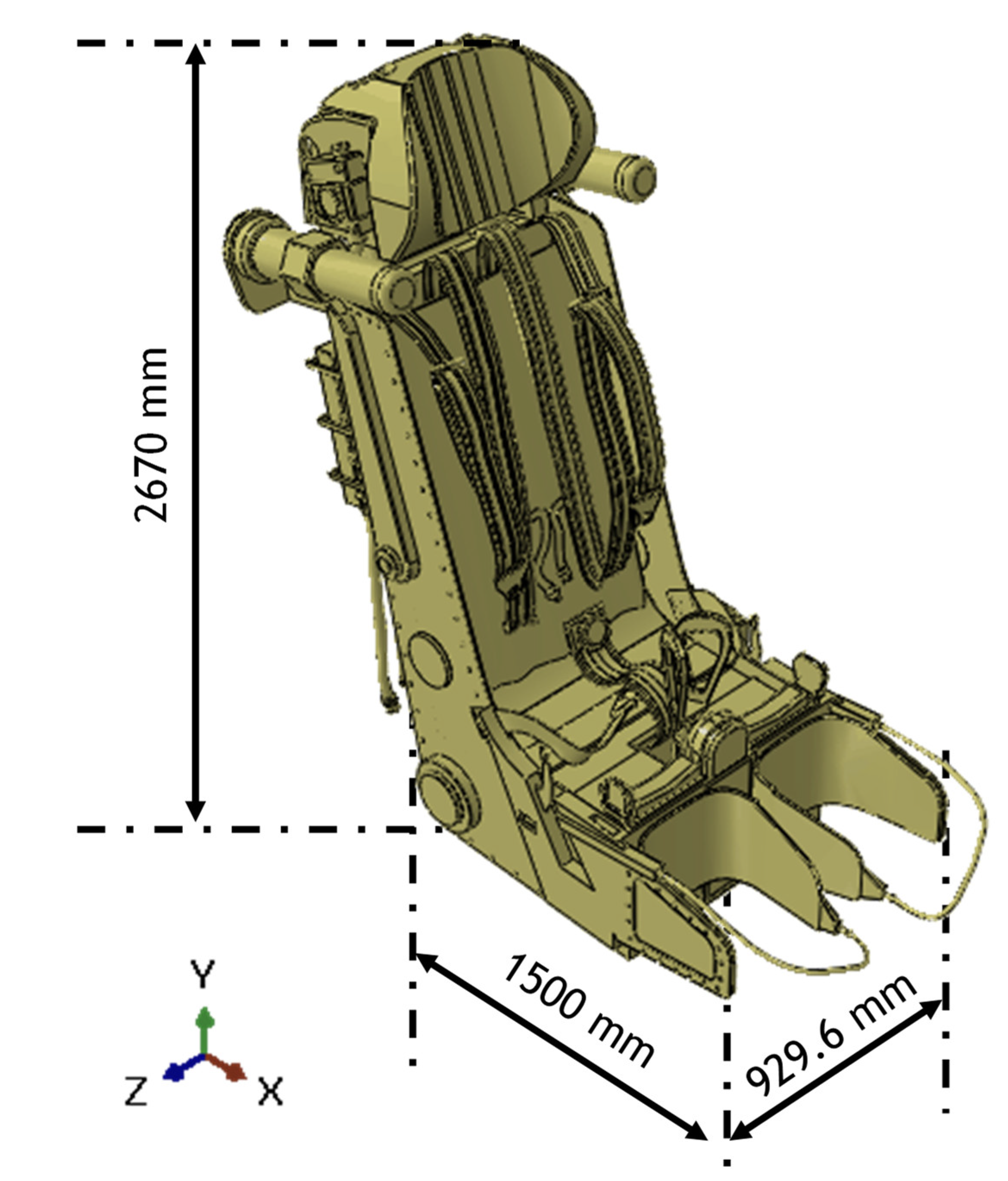
Modern aircrafts adopt a fourth-generation ejection seat system that includes a rocket propulsion systems and sensors to monitor the aircraft’s altitude and speed, which are important factors for the ejection. An example of a modern ejection seat [
31] is shown in
Figure 1.
Among the various injuries that the ejection can cause to pilots, the spinal compression due to the axial pulse is the most common and dangerous. Therefore, the management of axial accelerations acting on the pilot during ejection become a main concern. In modern seats, the ejection thrust is strictly controlled to ensure a safe ejection.
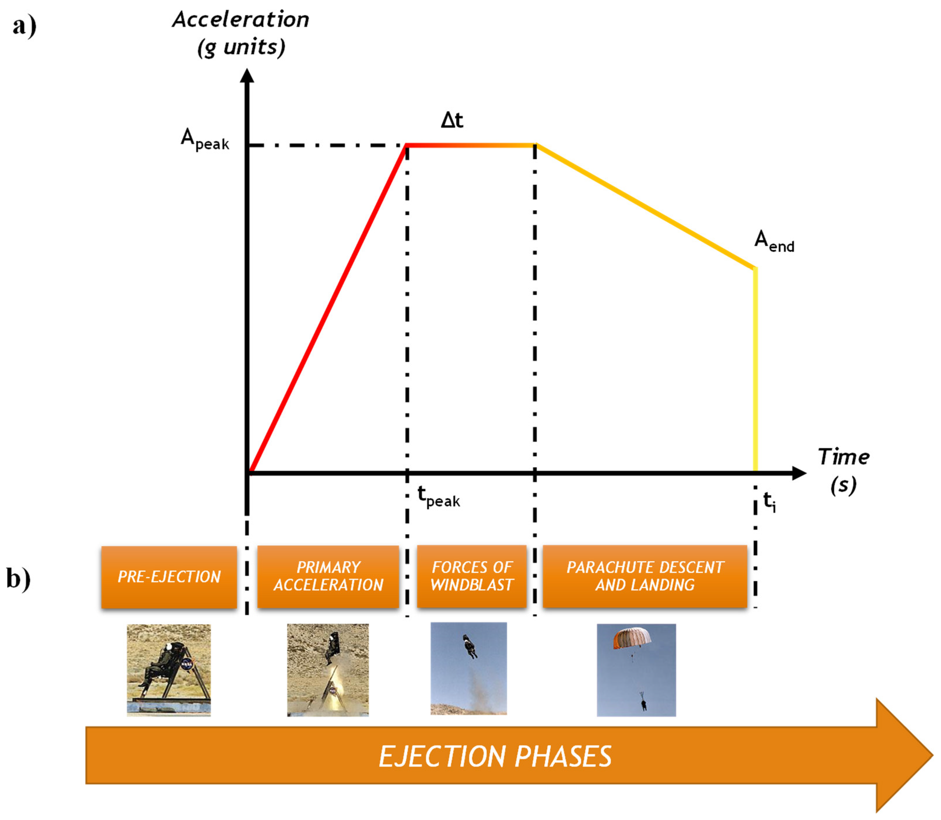
As illustrated in
Figure 2, according to military standards [
32,
33,
34] the ejection axial acceleration is schematized by means of a trapezoidal shape in the plane acceleration vs. time.
To provide a quantitative read of
Figure 2, the ejection motion parameter ranges are listed in
Table 1.
The first step of the ejection is the pre-ejection. This phase describes the time interval between the instant when a dangerous situation occurs and the beginning of the ejection. In some flight conditions, for example during landing and take-off, this time interval is very short and the pilot does not have enough time to prepare the aircraft for an optimal and completely safe ejection. The pilot has the time to adapt the aircraft for an optimum ejection by, for example, reducing the flight speed for in flight conditions, such as while in cruise
The second ejection step is known as “primary acceleration”. In this process, first by activating an explosive charge and then with the aid of rockets, the pilot-seat system is accelerated out of the cockpit with an acceleration ranging from 12 g to 30 g. This is the ejection phase where the pilot is most exposed to injuries. The seat, during the primary acceleration phase, actually exerts on the aircraft structure an inertial force due to this acceleration. Therefore, a reaction of the aircraft structures is applied to the seat and, hence, to the pilot.
After this phase, the pilot-seat system is subjected to an approximately constant acceleration due to the aerodynamic resistance in relation to the altitude variation. This phase is schematized in
Figure 2 with the name “Forces of windblast” and can last a variable amount of time depending on the ejection conditions.
The last phase is the parachute descent and landing. Since the impact between the seat–pilot system and the ground occurs at about 6 g [
35], significant injuries can also occur during landing. Moreover, injuries can, potentially, also arise due to the shock of opening the parachute.
This work investigates the effectiveness of an energy absorbing system composed of five shock absorbers designed to take into account the capabilities of additive manufacturing in order to alleviate the loads acting on the pilot during the initial explosion that produces the upward acceleration of 12 g.
3. FE Model
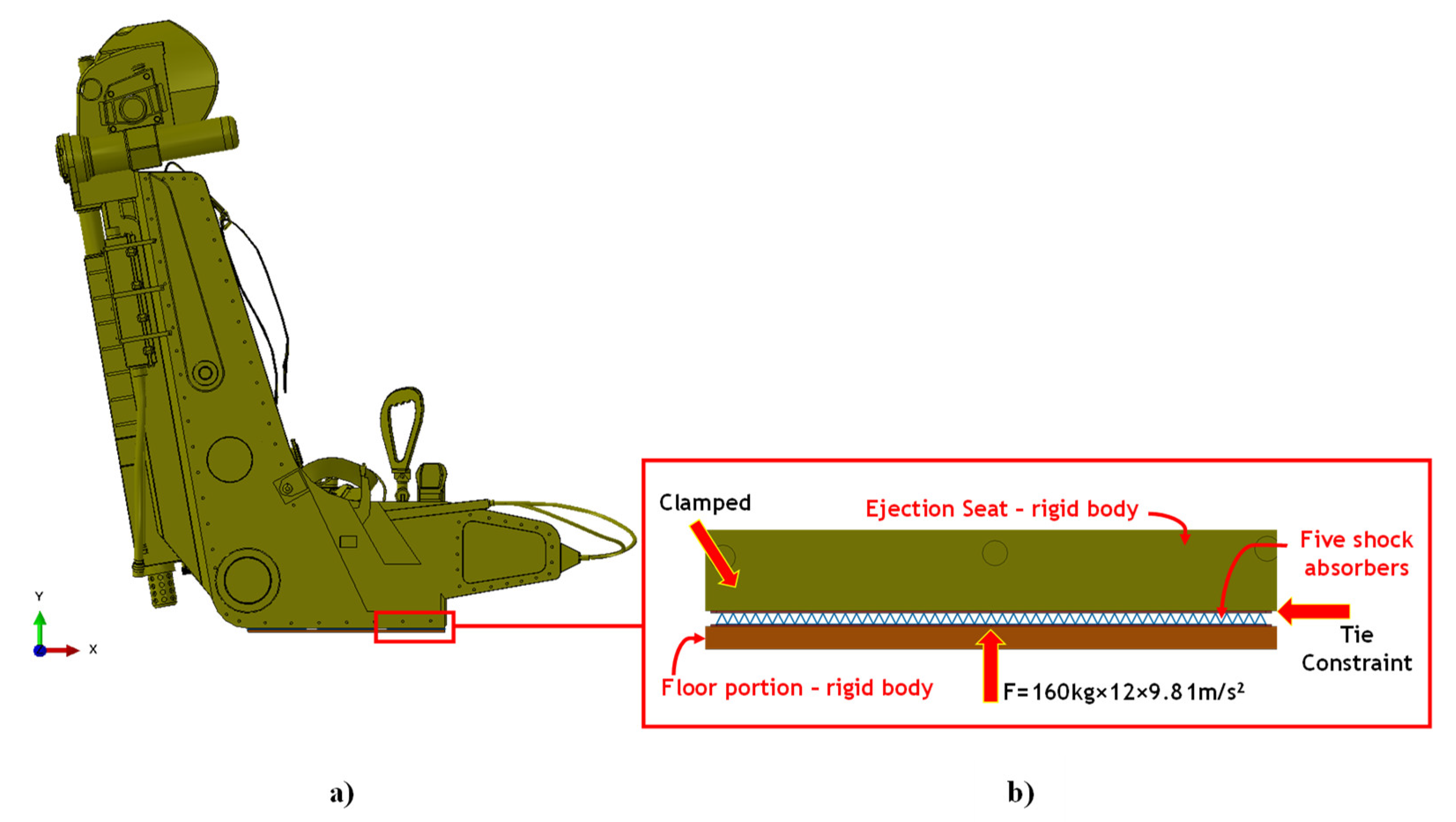
In the present work, to evaluate the effectiveness of the proposed new shock absorber concept obtained by combining composite materials with additive manufactured metallic structures, numerical impact simulations have been carried out. An infinitely rigid aircraft floor portion under the seat has actually been accelerated to 12 g towards the seat in the Abaqus explicit finite element environment. The proposed shock absorber system has been positioned under the seat, between the seat and the floor. These simulations allowed comparison of the rate of energy absorbed by the proposed absorber system to the energy produced during the impact, thus measuring the real benefit offered by the absorbers.
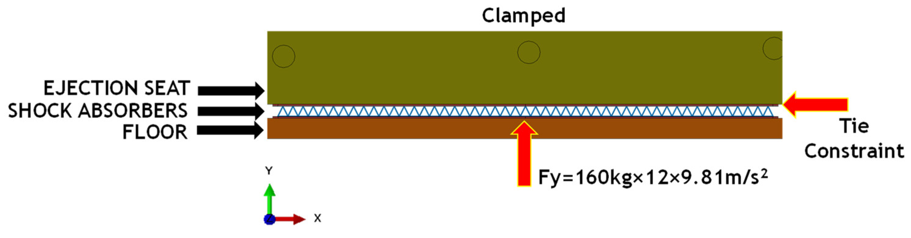
A scheme of the forces acting on the interacting bodies during the initial explosion is provided in
Figure 3.
3.1. Numerical Model
The numerical model investigated in the present work can be seen as an evolution of the panel shown in [
26]. Indeed, in [
26] a panel with dimensions of 155 mm × 155 mm × 6 mm was analysed; while here, for the considered application, it has been necessary to design five panels, each one with dimensions of 250 mm × 250 mm × 6 mm, in order to protect a sufficient area under the seat.
Moreover, considering the high computational cost due to the large degree of freedom of this numerical model related to the complex lattice structure, the metal lattice core has been simulated by adopting one-dimensional beam elements.
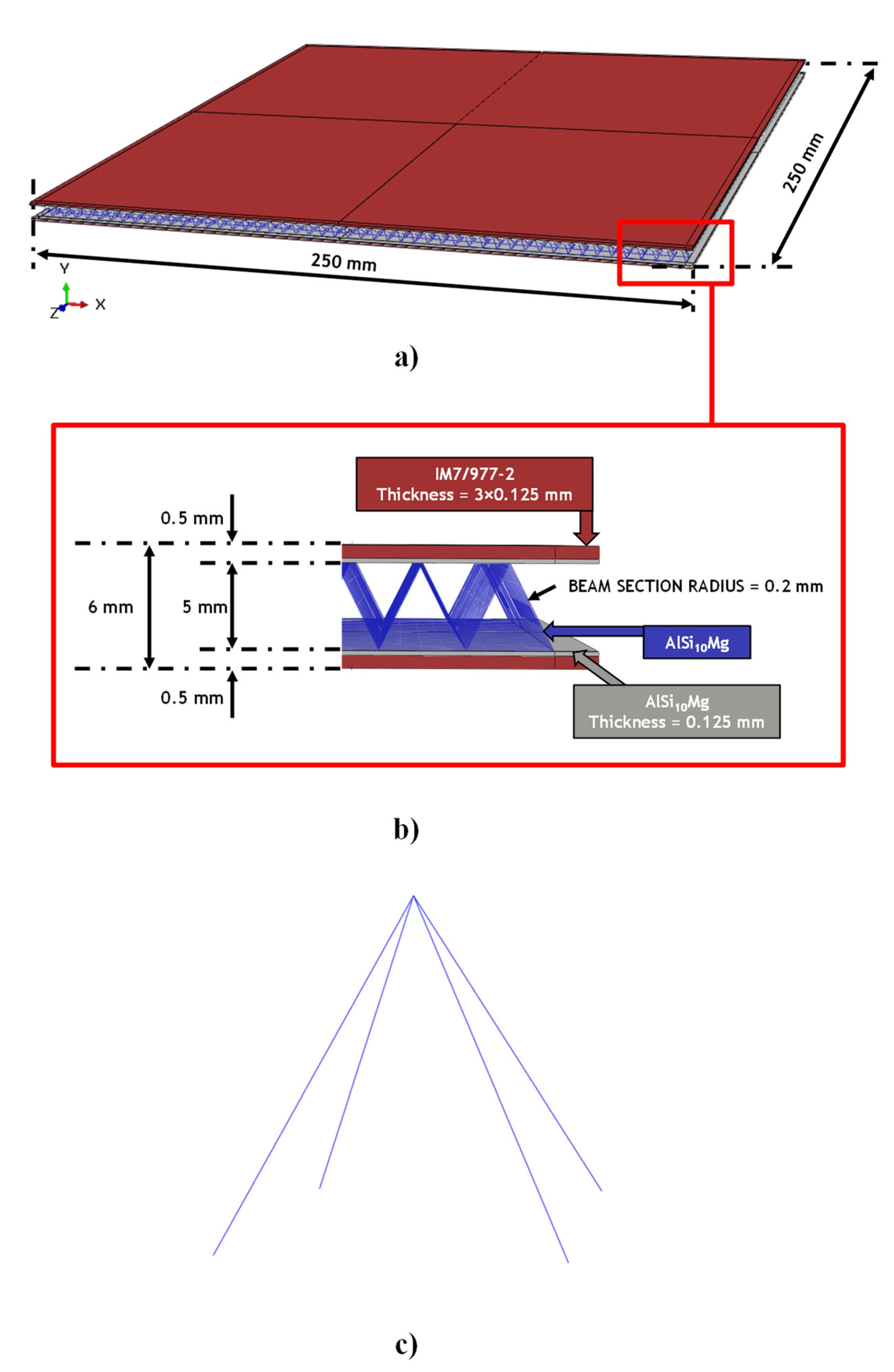
The material systems used for the components of the proposed shock absorber panel and its geometrical description are shown in
Figure 4.
The internal core of the panel is constituted by a lattice pyramidal structure with base and height of 5 mm and a strand diameter of 0.4 mm. This configuration for the lattice domain was selected according to the conclusions of [
26], where the authors demonstrated that the pyramidal unit cell, in comparison to other unit cells, can provide the best compromise in terms of mass reduction and energy-absorbing capability.
As shown in
Figure 4, the metallic lattice part, as well as the internal plates, are made of AlSi10Mg. This aluminum alloy powder has been demonstrated to provide excellent mechanical performance in terms of energy absorption [
36,
37,
38] when specifical printing parameters are adopted.
The external coating of the metallic part has been done by using three layers of IM7/977-2 composite material system on each side with a stacking sequence of [45°; −45°; 0°]. The thickness of each skin layer, for both the metallic and composite layers, is 0.125 mm.
The mechanical properties of the adopted material systems are listed in
Table 2 and
Table 3, respectively, for the elastic and plastic properties of the AlSi10Mg alloy [
36] and in
Table 4 for each single IM7/977-2 composite material layer.
The numerical modeling of metal skins has been performed by adopting 3D C3D8R Abaqus elements. These are 8-node linear brick elements with a reduced integration scheme and hourglass control; whereas, for the composite components, continuum shell elements with a reduced integration scheme have been adopted. These elements are defined by three-dimensional modelling even if they use the classic lamination theory. Thus, the Hashin failure criteria can be employed for the assessment of intra-laminar damages. For the ejection seat, the cad model of the latest generation K-39 LT seat was imported. This seat has been imposed as an infinitely rigid body and its general dimensions are displayed in
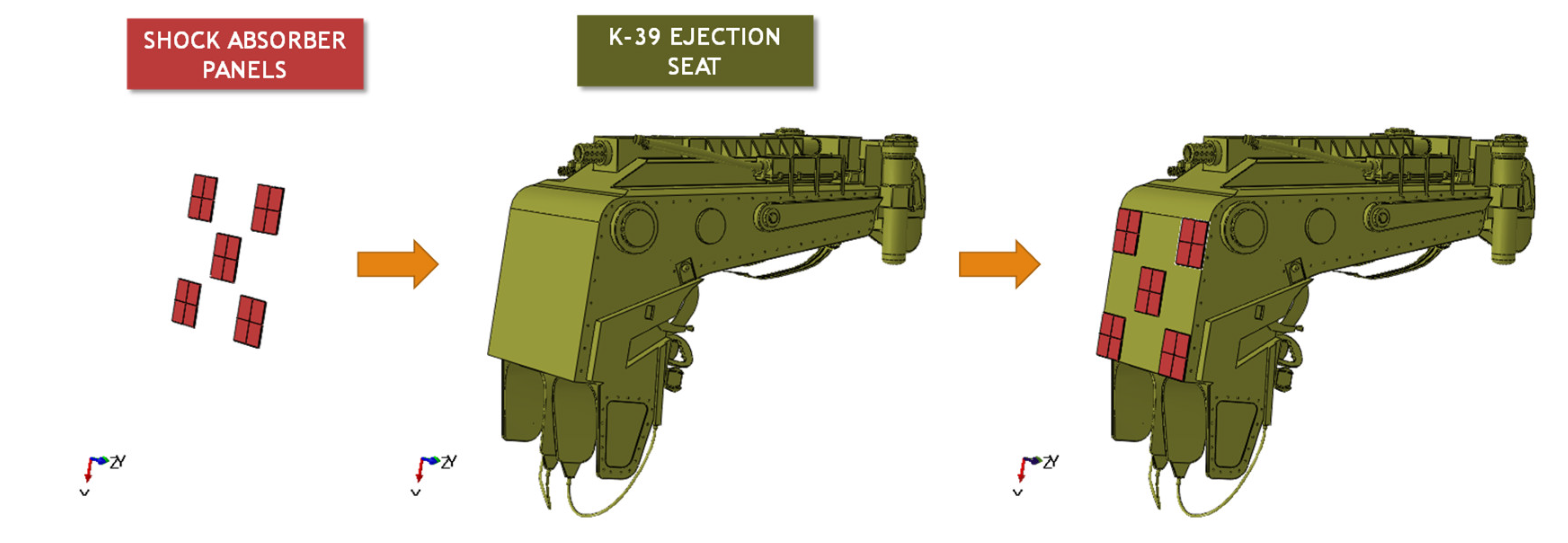
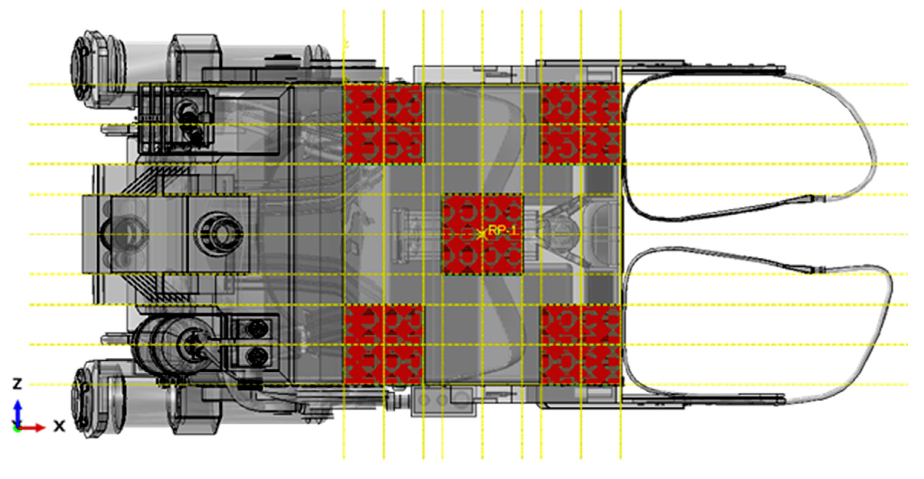
Figure 5.
Figure 6 and
Figure 7 describes the integration between the system of the five hybrid shock absorber panels and the K-39 LT ejection seat. The contact between these two parts has been defined by adopting tie constraints.
The mass of the entire proposed absorber system is 1.21 kg. Consequently, each of the five sandwich panels has a mass of 0.24 kg. In detail, the metallic part of each panel has a mass of 0.11 kg. The lattice core for each panel has a mass of 0.03 kg. The composite part of each panel has a mass of 0.13 kg.
According to the military standards, this numerical model considers 160 kg as total mass of the seat–pilot system.
3.2. Sensitivity Analysis
To select the correct finite element size for the metallic core component and to ensure accurate numerical results for the core component modelled with one-dimensional Beam elements, a mesh sensitivity analysis has been carried out. In fact, the energy absorbed by a panel, for various size of the beam elements in the lattice core, has been compared to the energy absorbed by a panel fully modelled with solid elements under an impact event at 20 J. The panel dimensions used for the sensitivity analysis and the applied boundary conditions are illustrated in
Figure 8.
The boundary conditions applied in this section were set by replicating those exposed in [
26]. In this reference article it has been demonstrated through comparisons with experimental and literature data, that the developed model subjected to the BCs exposed in
Figure 8 is able to represent with high accuracy the real behaviour of the shock absorber.
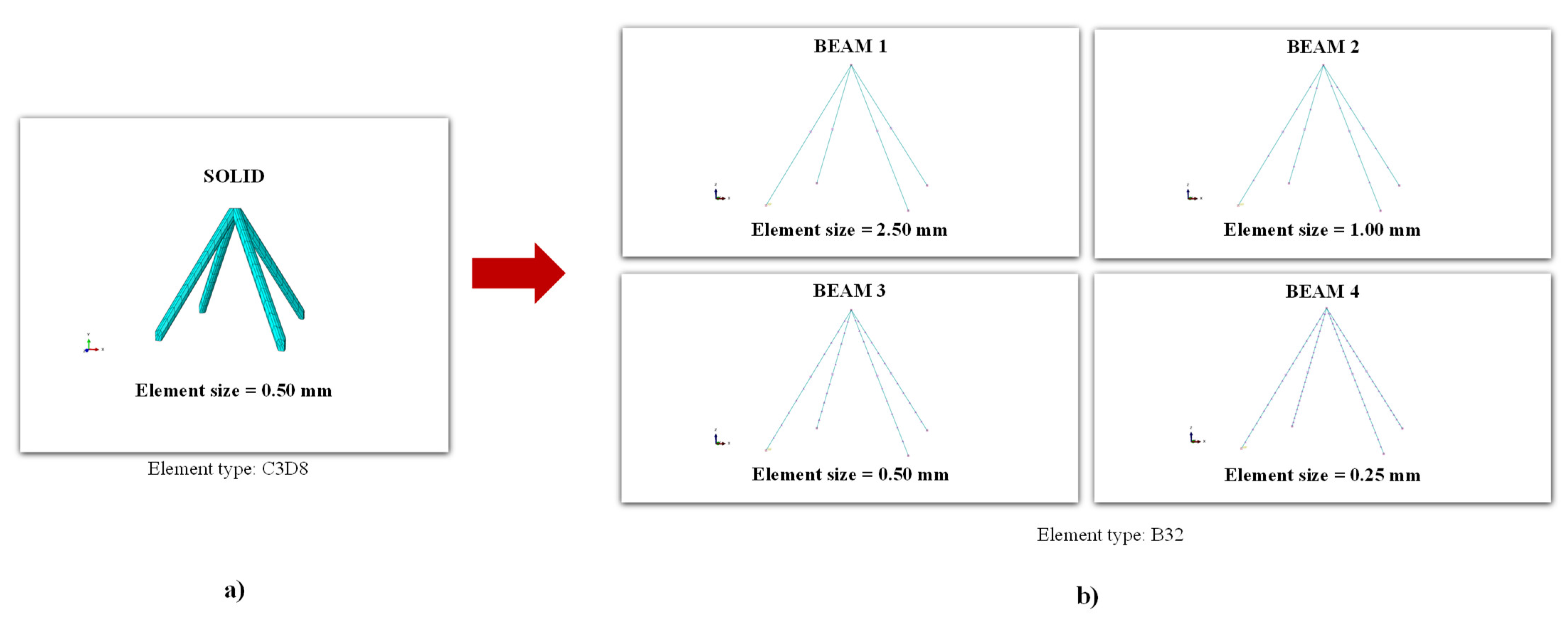
According to the conditions shown in
Figure 8, four impact analyses at 20 J have been carried out where, as shown in
Figure 9, four different sizes (BEAM1: 2.5 mm, BEAM2: 1 mm, BEAM3: 0.5 mm and BEAM4: 0.25 mm) of the beam elements of the lattice core have been used.
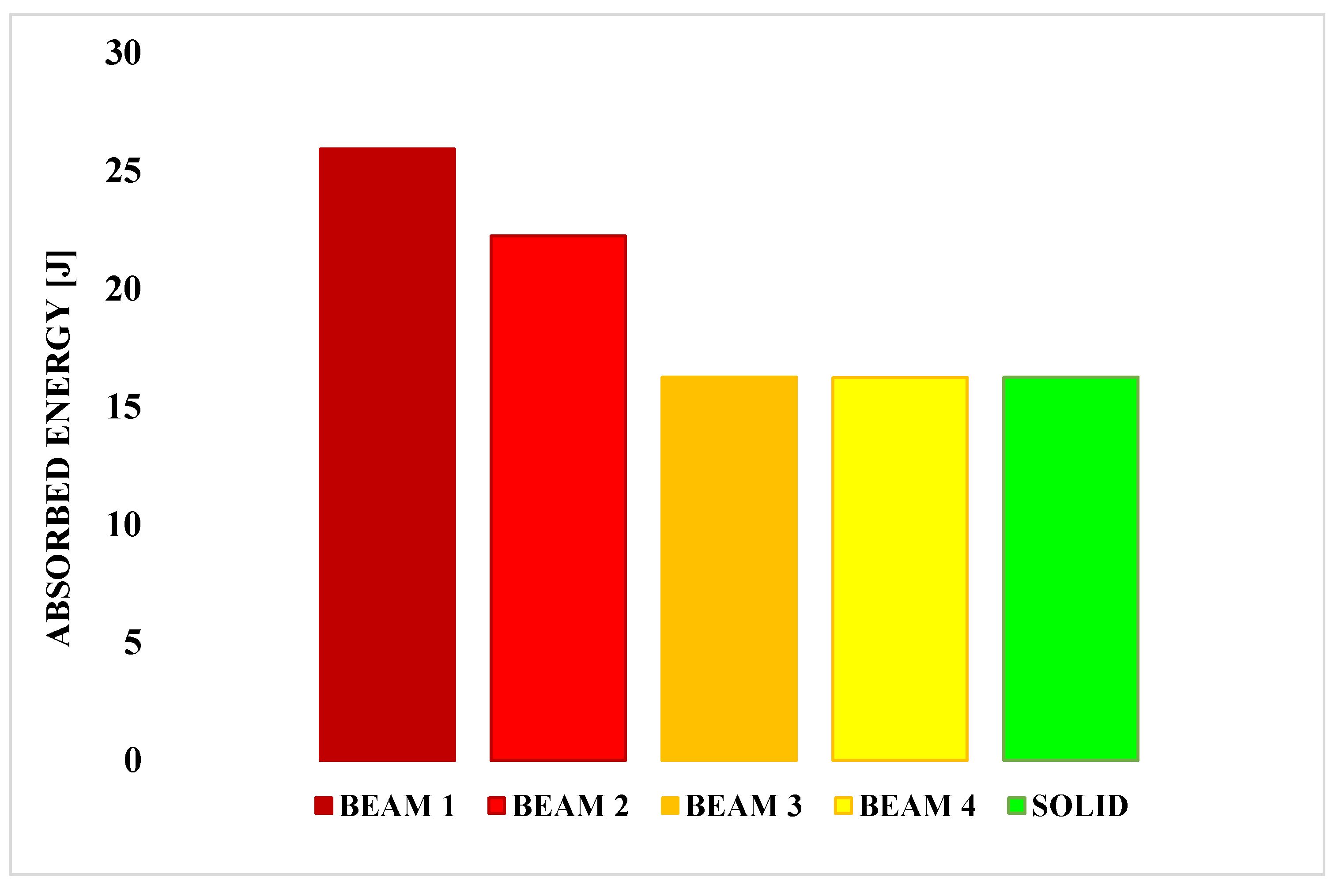
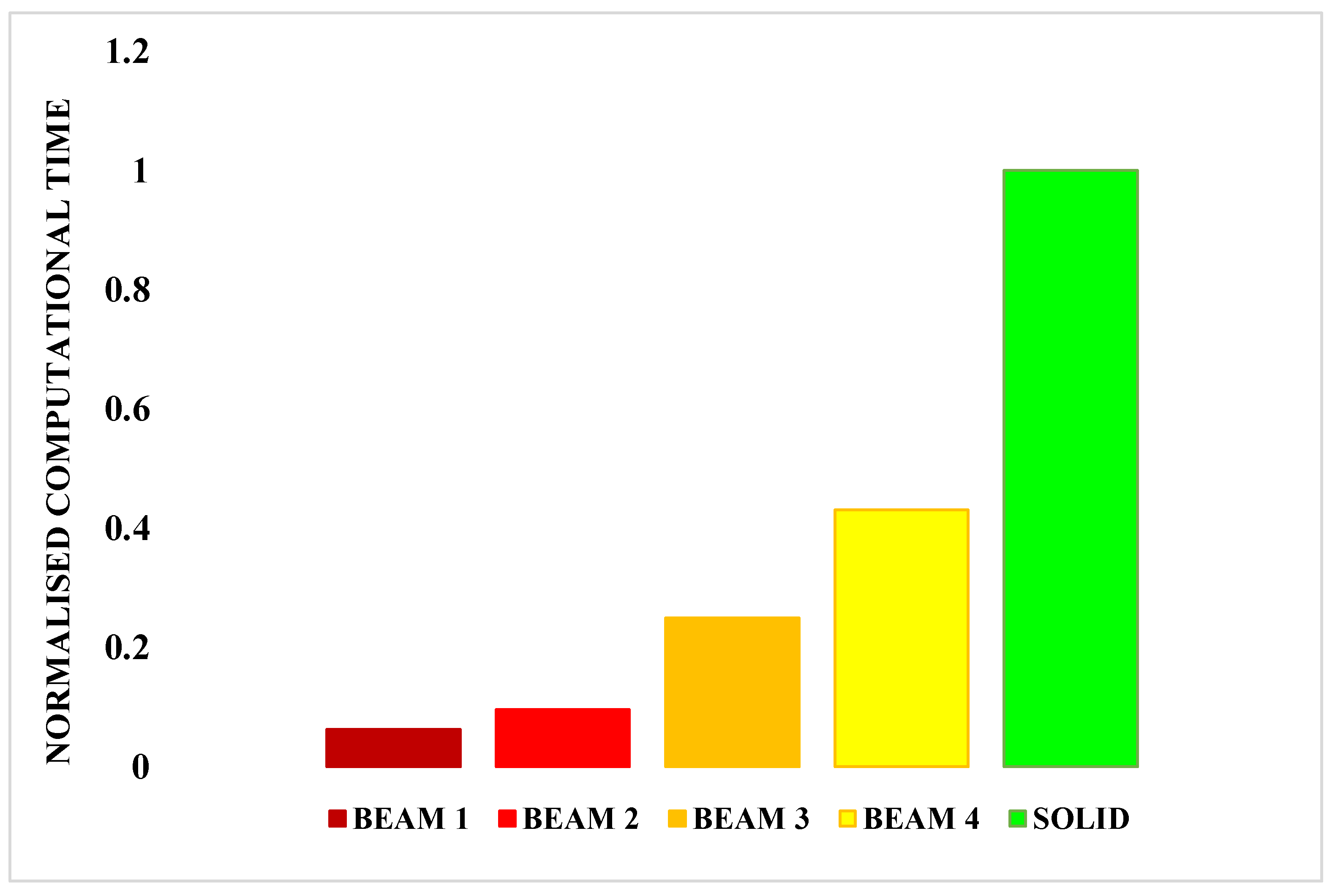
Figure 10 relates the energy absorbed to the four investigated beam configurations and by the solid configuration, while
Figure 11 compares the normalised computational times of the four investigated beam configurations to the normalised computational time of the solid configuration. The computational time has been normalised by the computational time of the solid model.
In
Figure 10, it can be appreciated that the BEAM 3, BEAM 4 and SOLID configurations are characterised by extremely similar values of absorbed energy. However, as it can be read in the histogram of
Figure 11, the BEAM 3 configuration shows a computation time 75% lower with respect to the one of the SOLID configurations.
Considering the proposed five absorber panel system is characterised by a large number of DoF, the BEAM3 configuration has been chosen for the modelling of the lattice core in the frame of the final impact simulations.
3.3. Setup of the Finite Element Simulations
The final FE numerical simulations are aimed at mimicing the explosive event occurring in the first 0.05 s of the primary acceleration phase. This event is extremely relevant to assess the effectiveness of the proposed shock absorber panel system. The simulation has been performed in the Abaqus explicit final element environment.
In terms of applied load for analysis, according to
Figure 12, a force in positive Y-direction, of magnitude evaluated as the product between 12 g acceleration (acceleration produced by the initial explosion) and a 161.21 kg (mass of the seat–pilot absorber system), has been applied to the infinitely rigid floor portion. According to this scheme, the floor portion pushes towards the bottom of the absorbers, bonded to the bottom of the seat by tie constraints.
In the definition of the contact between the rigid floor and the shock absorber system, was set a “normal behaviour” defining a “hard” pressure-overclousure, and a “tangential behaviour” with a penalty type formulation and a friction coefficient of 0.3.
4. Numerical Results
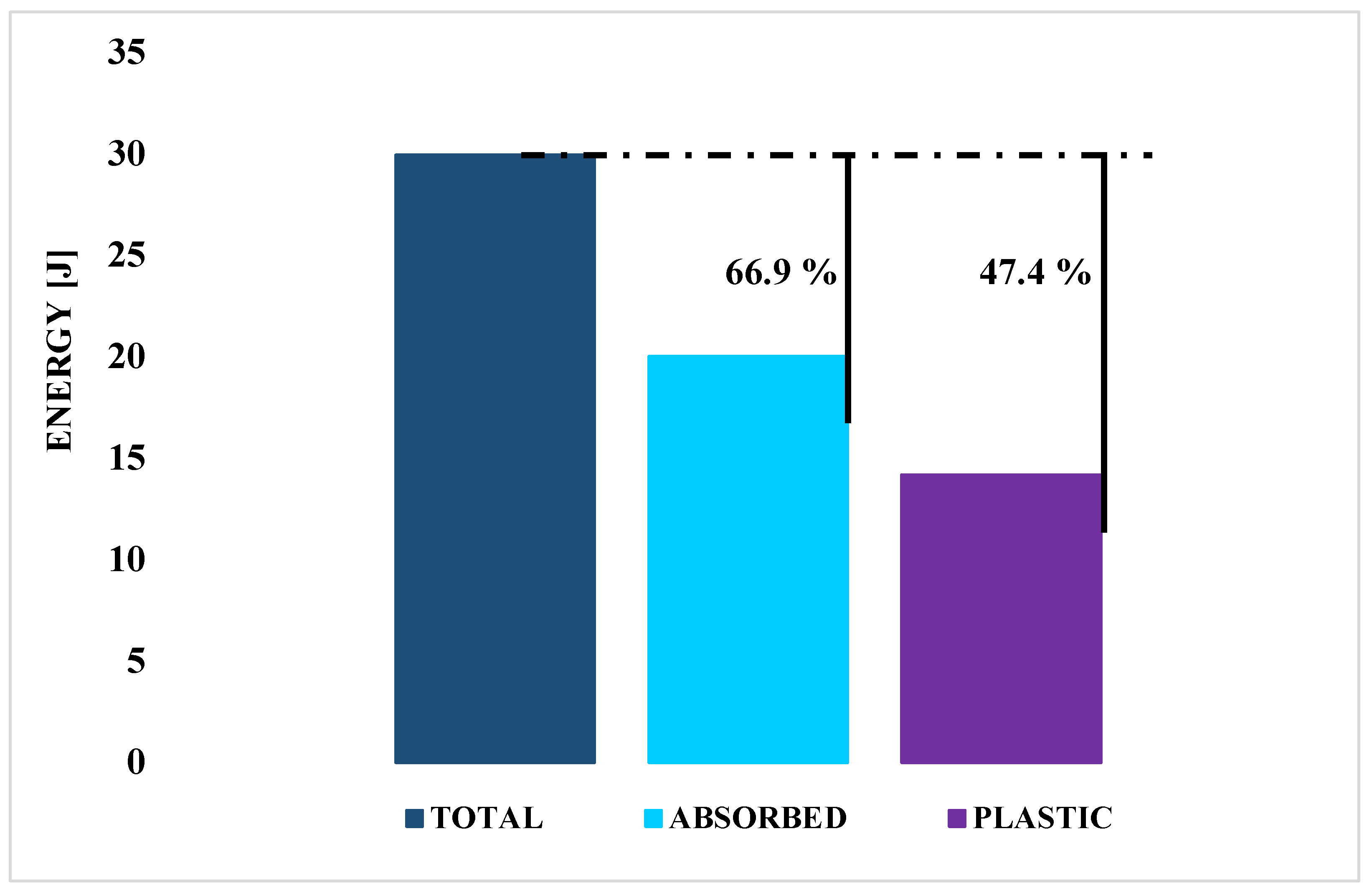
A measure of the contribution of the proposed shock absorbing system during the explosive event at the beginning of the primary acceleration phase of the ejection, can be provided by the rate of absorbed energy. Therefore, in
Figure 13, a diagram that compares the total energy produced during the explosion, the total energy absorbed that is calculated as the sum of the energy absorbed through both plastic deformation and fracture of the metallic component, and the amount of plastic energy absorbed by the mechanism under investigation is provided.
The amount of energy absorbed by the absorption system was recorded by measuring the value at which the internal energy calculated by the software during the numerical simulation stabilises.
As shown in
Figure 13, assessing the energy comparison, by increasing the mass of the seat–pilot system by less than 0.8%, it is possible to absorb about 66.9% of the energy arising during the explosion taking place in the first part of the seat ejection event.
This value of 66.9% was determined by calculating the percentage difference between the total energy measured (ETOTAL) and the internal energy (ALLIE), once stabilised.
Moreover, the contribution provided by the integration of the additive manufactured metallic component as core between the composite skins can be pointed out. Indeed, from
Figure 13, it can be observed that about 47.4% of the energy arising during the explosion is absorbed by plastic deformation within the core, while about 19.5% of the energy arising during the explosion is absorbed by fracture of metallic components.
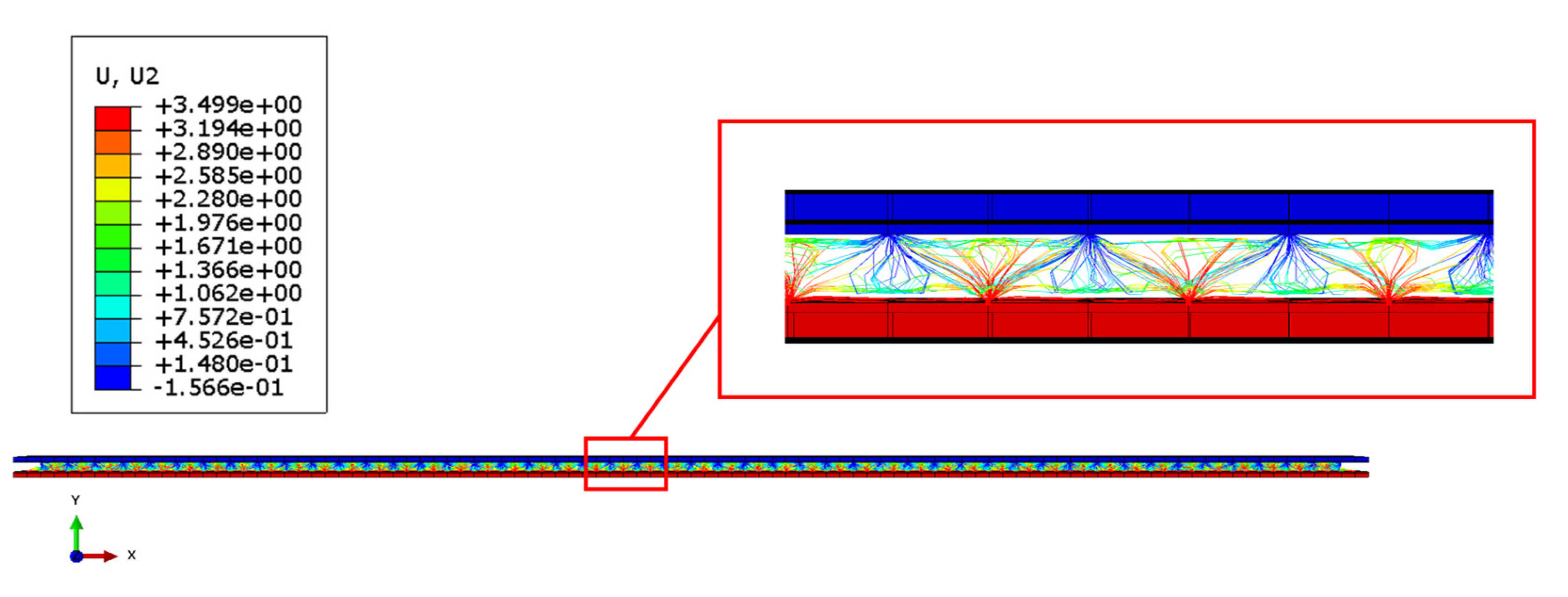
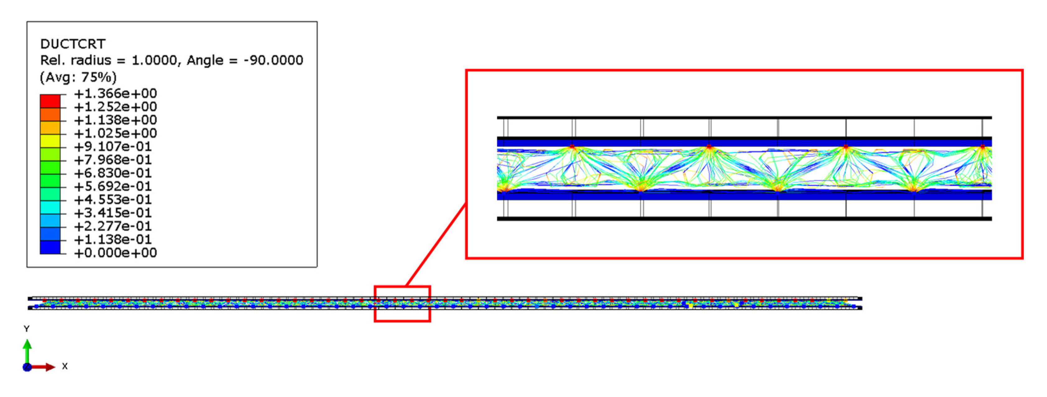
Finally,
Figure 14 and
Figure 15 introduce, respectively, the deformation obtained from the sandwich panel and the breakages of the metallic component, at the end of the numerical simulation.
In detail, the parameter DUCTCRT exposed in
Figure 15 includes ductile, shear, forming limit diagram (FLD), forming limit stress diagram (FLSD) and the Müschenborn–Sonne forming limit diagram (MSFLD) criteria for damage initiation in ductile metals and, in particular, includes in Abaqus/explicit the Marciniak–Kuczynski (M-K) and Johnson–Cook criteria for the evaluation of the damage initiation.
As can be appreciated in
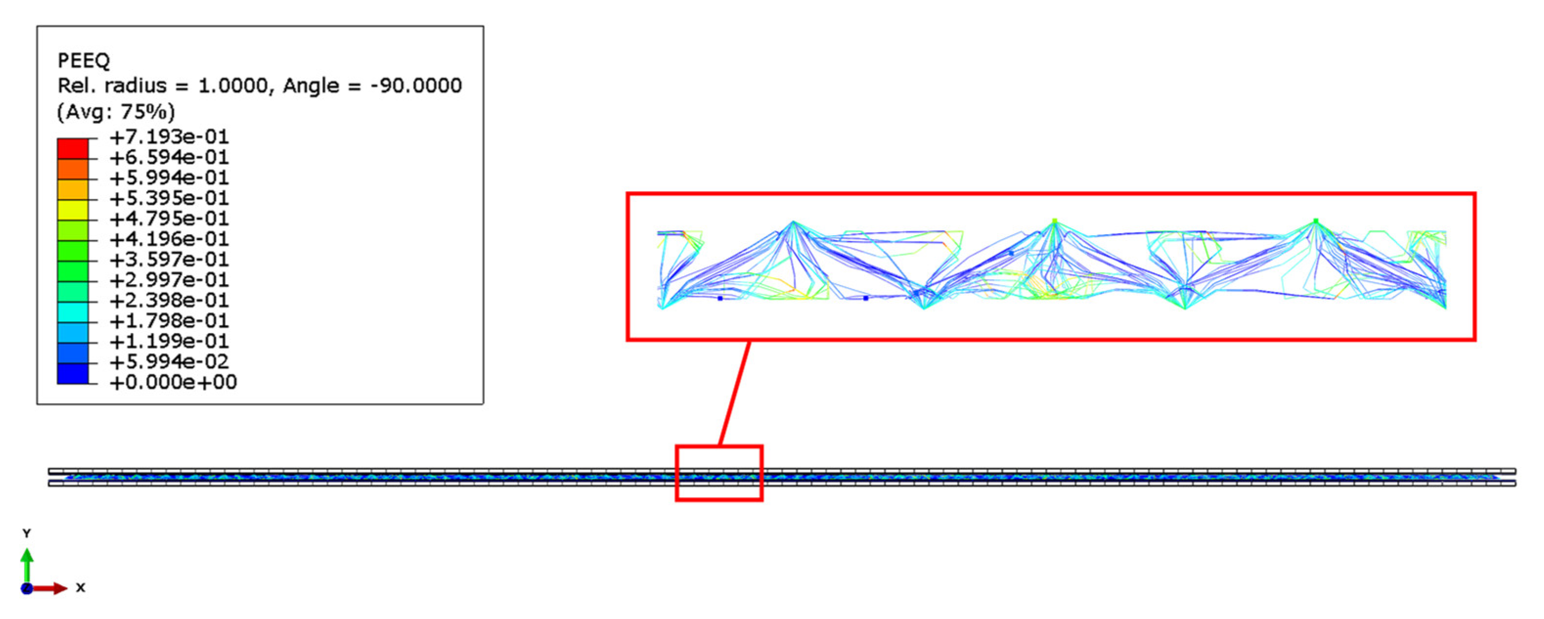
Figure 14, the thickness of the panels after deformation reduces to about half of the initial thickness. Furthermore, from
Figure 15, it is clear that the damages of the metallic core are condensed at the vertices of the pyramidal structures, while in
Figure 16, the plastic strain in the metal lattice core can be appreciated.
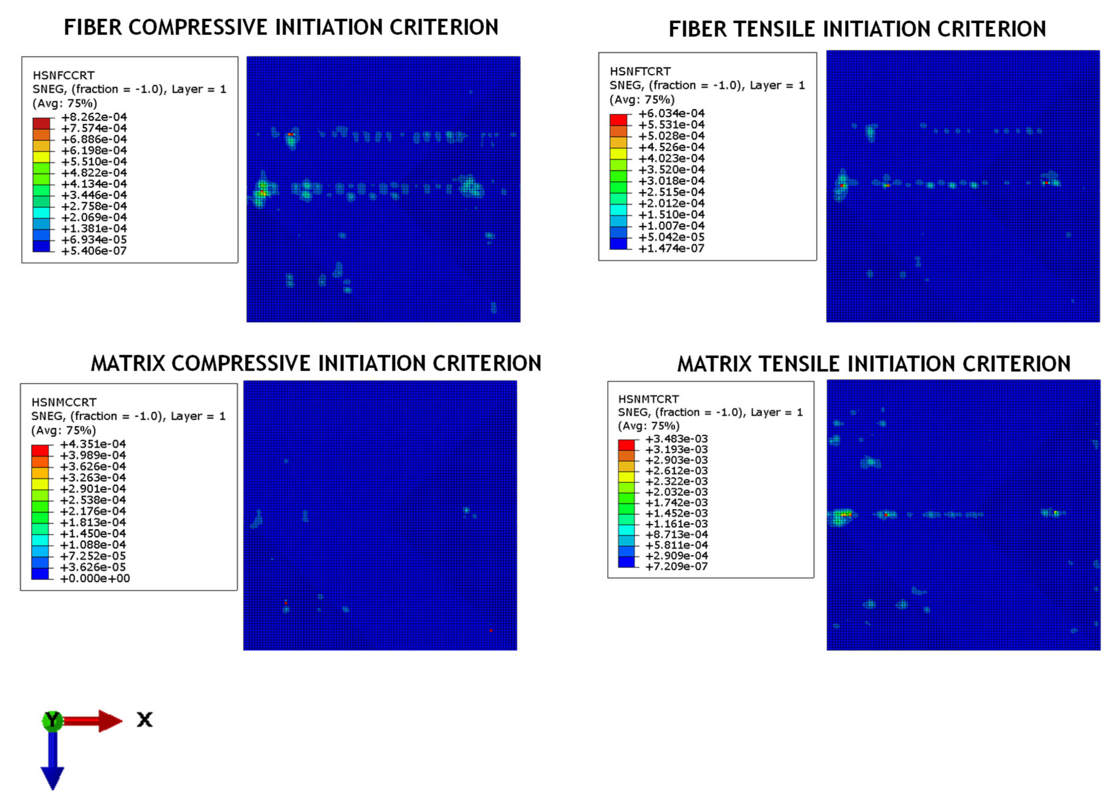
Since the load has been distributed on the shock absorber panel surfaces without localization in specific areas, the intra-laminar failure of the fibres and the matrix in the composite components has not been observed. Indeed,
Figure 17 shows that the Hashin failure criteria for fibre and matrix compression and tension has not been matched in any ply of the composite skins.
5. Conclusions
When developing any type of transportation structure, the occupants’ safety during accidents is one of the most critical issues. Hence, a key role is played by design solutions maximizing crashworthiness performance and easily implementable for several applications.
In this work, the preliminary numerical assessment of the effectiveness of a new additive manufactured hybrid (metal/composite) shock absorber concept during the ejection of a military seat has been carried out.
The novelty of the proposed concept lies in employing the capabilities of additive metal printing to provide a thickness of only 6 mm to the shock absorption system. Such thin shock absorber systems able to absorb the energy values specified in this work have not been found in the literature.
Furthermore, due to the extremely thin thickness of the shock absorber, it can be easily integrated into the aircraft structure in many key positions, such as at the interface between the ejection seat and the floor.
The merging of the advantages offered by additive technology through the customization of a metallic core able to maximize energy absorption, with the advantages in terms of high strength and lightness performance typical of composite materials, employed as external coating of the panels, has been demonstrated to potentially produce considerable improvements for the safety of pilots during the ejection event. The numerical simulations demonstrated that, by increasing the total mass of the seat–pilot system by less than 0.8%, the proposed new shock absorber system is able to absorb about 66.9% of the impact energy acting in the first phase of the ejection event. In such a way, the reduction of the intensity of the loads acting on the pilot also drastically increases his safety and reduces the probability of occurrence of significant injuries during the ejection events.


