
Thermal Characteristics and Parametric Analysis of an Improved Solar Wall


1
College of Architecture, Texas A&M University, College Station, TX 77843, USA
2
Department of Civil Engineering, Zhengzhou University, Zhengzhou 450001, China
3
Department of Construction Engineering, Dalian University of Technology, Dalian 160003, China
*
Author to whom correspondence should be addressed.
Appl. Sci. 2021, 11(14), 6325; https://doi.org/10.3390/app11146325
Submission received: 31 May 2021
/
Revised: 23 June 2021
/
Accepted: 7 July 2021
/
Published: 8 July 2021
(This article belongs to the Special Issue Smart and Energy-Efficient Buildings: From Energy Modeling to Applications)
Abstract
:Solar air collectors installed on buildings can significantly reduce conventional energy consumption in winter and summer. However, some problems arise in the utilization process, such as overheating, inconvenient operation control and low energy efficiency, etc. This work is a parametric analysis focusing on the automatic control and thermal efficiency improvement of the solar wall. An improved color-changing solar wall integrated with automatic control components, such as a photoelectric fan and temperature-controlled damper, was proposed in this paper. Based on the experimental data, the average daily heat output of the color-changing solar wall is 1.08 MJ per unit floor area on clear days in winter and the average thermal efficiency is 56.8%. Meanwhile, a quantitative analysis was carried out based on monitoring experiments for evaluating the thermal characteristic of automatic control components. Furthermore, in order to improve the thermal performance of the solar wall, parametric analysis was performed by numerical simulation. Results from this paper can provide a theoretical basis for the application of solar air collectors in modern buildings.
1. Introduction
As a type of renewable energy, solar energy is widely used as an alternative to fossil energy, and has the highest potential to meet the ever-increasing energy demands. Since the middle of the last century, solar air heating has aroused great interest in the community of solar researchers because it is a relatively simple, inexpensive and low maintenance application [1]. As a typical component of passive solar air heating, solar air collectors are mainly used to convert incident solar radiation into useful heat in different types of buildings. These heat collectors have been adopted around the world to reduce fossil fuel consumption for space heating and domestic hot water production [2]. Along these years, several types of solar air collectors, differentiated by the type of solar absorber element (flat plate, V-corrugated plate, cylindrical tubes, plates with fins, etc.) were designed, mathematically modelled and experimentally tested [3,4]. The thermal performance of different types of solar air collectors is studied and compared in Table 1. Among them, the most common system used for absorbing solar irradiation is the flat-plate solar air collectors, which are always integrated on building façades as passive heating components.
To improve the efficiency of solar energy, there are extensive studies and efforts have focused on improving the heat efficiency and optimizing the structure of solar air collectors [12,13,14,15]. A more effective approach is to maximize the contact between the circulating air and the absorber plate through forced turbulence in double channel, including V-corrugated or sine-wave absorber plates, with fins, baffles or ribs [16,17,18].
Taking the instantaneous efficiency of the collector as an evaluation index, Zhang et al. [19] proposed optimal structure design parameters of the flat-plate solar collector by numerical simulations. To simulate the thermal behavior of single/two-glass-cover solar air collector systems, Bahrehmand et al. [20] built a mathematical model. Debnath et al. [21] investigated the performance of the solar air collector in North Eastern India, and various parameters considered for the present investigation were collector tilt angles, single and double glazing, mass flow rate and two different absorber plates. In reference [22], an innovative solar water heater integrated with a linear parabolic reflector was proposed and experimentally tested, and the experiments showed that the device was effective during winter. Its mean daily efficiency varied between 36.4% and 51.6%. Şevik et al. [23] investigated the performance of two types of solar air collectors with aluminum absorbers at three different air mass flow rates. Results showed that an enhancement of 15.9–41.2% in thermal efficiency was achieved in comparison to the flat plate solar air collector. Alta [24] compared the performance of three different types of designed flat-plate solar air heaters by the energy and exergy analyses. He found that the heater with double glass covers and fins is more effective.
There are different factors affecting the solar air heater efficiency, e.g., aspect ratio of collector, absorber materials, vent size, wind speed, etc. [25,26,27,28]. To improve the disadvantages of solar air heaters, a range of numerical simulations has been performed for thermal performance optimization [29,30,31]. A mathematical model based on a numerical finite-difference approach was proposed for a flat-plate solar air collector in reference [32]. Nikolić et al. [33] presented a mathematical model to determine the optimum reflector position of a double-exposure flat-plate solar collector using FORTRAN language. Based on the two-node lumped heat capacitance method, dynamic thermal performance prediction models for flat-plate solar collectors were proposed and validated using dynamic tests [34]. The thermal behavior of double parallel flow air heating collectors working by natural convection was also studied. A GTC (glazed transpired solar collector) with perforating corrugated plate was developed by Zheng et al. [35], and the simulated results showed that its thermal performance and economic characteristics were better than other transpired solar collectors.
Due to the above studies, buildings integrated with passive solar heating systems are widely used because of the high heat efficiency of solar air collectors [36,37,38,39,40,41,42]. Pertinent literature reveals that a good number of investigations are carried out in the recent past. However, some problems also have not been solved during the application of solar air collectors, such as overheating during summer and inconvenient operation control by manual dampers. A concept of “passive heating and cooling by color-changing” was put forward in our previous research [43,44], and an experimental study of thermal responsive of the color-changing solar wall was carried out. However, there are still some problems, such as inconvenient manual control operation and low thermal efficiency. Therefore, the aim of this work is to propose the automatic control component and optimize the heat collection efficiency.
To achieve this goal, the design and construction of this solar wall are detailed, photoelectric fan and temperature-controlled damper are proposed and thermal characteristics of these automatic control components are evaluated by measuring hygrothermal parameters. Meanwhile, parametric analysis was performed based on the mathematical model and the optimization results of thermal performance simulation are presented. As an outcome, the finding of this research may provide some suggestions on the energy efficiency design for newly-built rural residences in cold areas, and present the theoretical basis and technical support for renewable energy utilization.
2. Development of Automatic Control Components Integrated with Color-Changing Solar Walls
Solar air collector is the core component of a passive solar house, which is mainly composed of outlet cover, absorber board, air gap, insulation plate, inlet, outlet and fans, etc. The optimum design of the solar wall is mainly to put forward the color-changing absorber board and automatic control components.
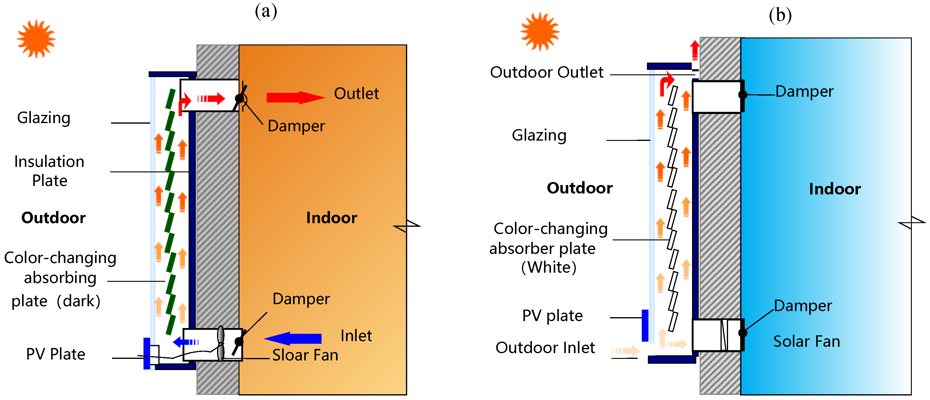
Studies about the color-changing absorber board had been carried out in reference [43] and [44]. The form of the absorber board is designed as a color-changing Venetian blind that exposes its black pieces outward in winter, whereas the white pieces are exposed outward in summer. The color of the absorber board is changed manually. The operation principle of the solar wall is shown in Figure 1.
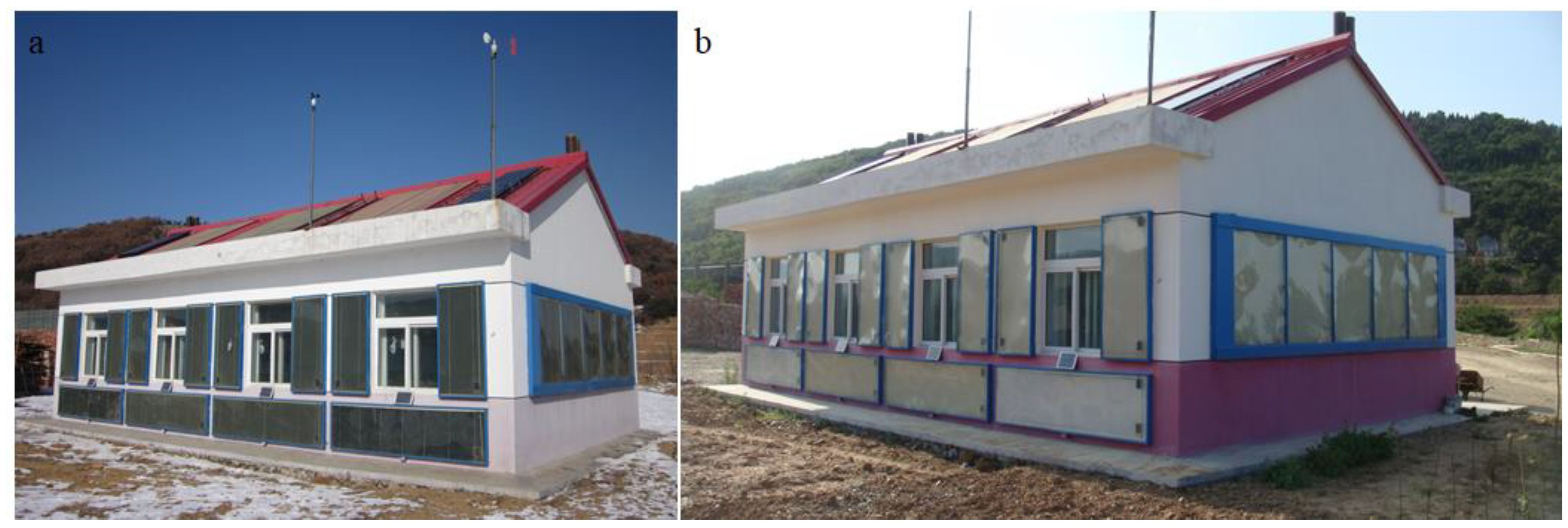
To analyze the thermal performance of solar walls, a full-scale experimental house integrated with solar walls was built in Dalian, China. The photo of the experimental color-changing passive solar house is shown in Figure 2. The building information and envelope characteristics are presented in Table 2 and Table 3, respectively. Color-changing solar walls were fixed on the south facade, facing to the south and perpendicular to the ground to heat up the living room and bedrooms. Dimensions of the solar wall system are shown in Table 4.
2.1. Application of the Photoelectric Fan
In the heat transfer mode, natural circulation is adopted for many heat collectors, such as the Trombe wall, which has the problem of low heat transfer efficiency. It is necessary to arrange fans. However, the problem of power supply should be solved and multiple AC power supply lines should be arranged. At the same time, manual control is not convenient, which is difficult to synchronize with the weather, and easy to cause problems, such as cold air backflow.
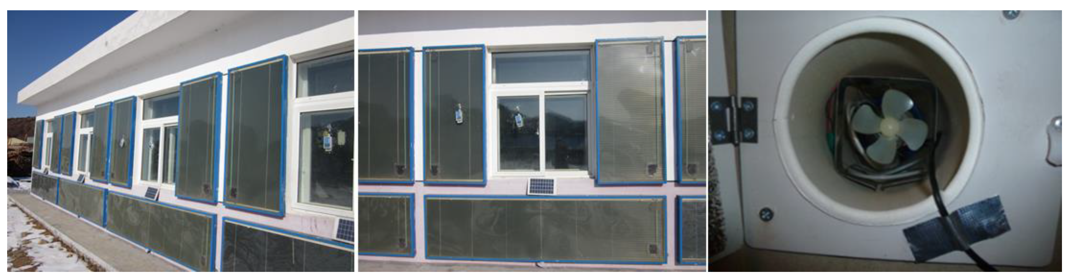
In view of the above problems, a photoelectric fan was proposed in this paper. The fan located in the lower vent can be driven by photovoltaic (PV) plates, which are installed outside (as shown in Figure 3), with the voltage of 12 V and the rated power of 6 W. The fan is used to force the hot air in the air gap. In particular, the problem of inconvenient manual control during the operation process can be solved. The fan speed and the mass flow rate are determined by solar irradiance.
2.2. Temperature-Controlled Damper Instead of the Traditional Wooden Damper
The traditional damper is usually made of wood and operated manually. Due to the rough production and moisture deformation of woods, etc., the situation of inflexible operation or unusable for dampers may occur in service. Furthermore, due to the manual operation, dampers are often forgotten to close on cloudy days or at night. Cold air in the air layer enters the room through dampers, resulting in lowering the indoor air temperature. It is difficult for users to accurately control the opening and closing time due to the variability of the outdoor climate. The electric damper can solve the problem of automatic operation, but it has the disadvantage that the upper and lower damper cannot be connected.
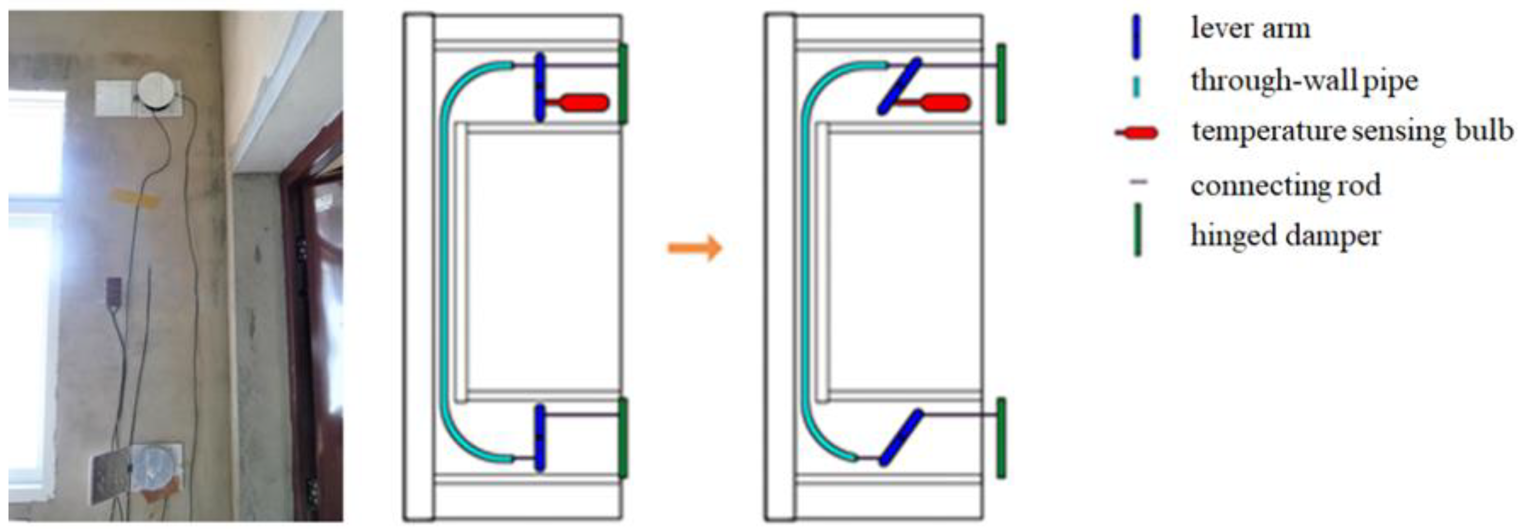
The temperature-controlled damper proposed in this study can solve the above problems. It is made of metal and non-deformation. Meanwhile, the damper can be controlled automatically according to the temperature. The temperature sensing bulb is mounted on the outlet, as shown in Figure 4. When the outlet temperature is over 20 °C, the bulb starts and the level-arm is moved from a vertical position to an inclined position. Then, the inlet and outlet damper are pushed by the connecting rod. Therefore, the function of opening and closing dampers can be achieved simultaneously. The higher the temperature is, the further the movement distance of the damper is.
3. Thermal Characteristics Analysis of the Improved Solar Wall
To investigate the thermal performance of this passive house, experiments were performed. As shown in Figure 5, the measured parameters of solar walls included surface temperature of plates, velocity in air gap, inlet and outlet. Indoor measurement parameters are mainly indoor air temperature, relative humidity, heat flow density and black globe temperature. The temperature and black globe temperature test points are located in the center of the room. All data were recorded every 10 min. The measuring instruments can be found in Table 5.
By the uncertainty analysis, in the present study, the uncertainties in the outlet air temperature, air mass flowrate and thermal efficiency are equal ±4.8%, ±0.026 % and ±5.8% for forced convection.
3.1. Effect of Solar Walls on the Indoor Thermal Environment and Energy Consumption
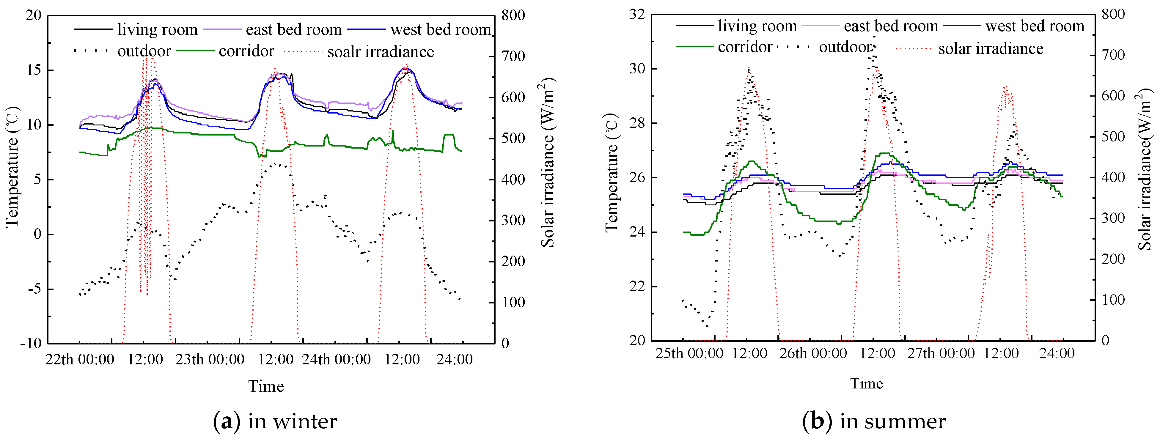
To analyze the heating and cooling effect of solar walls under extremely climate weather, the monitoring data of three hottest days in summer (from 29 August to 31 August) and coldest days (from 24 January to 27 January) in winter were selected. The indoor air temperature of different rooms is shown in Figure 6.
As shown in Figure 6a, during the winter, the indoor air temperature was above 10 °C because of the passive heating of the solar wall. While the outdoor temperature fluctuated between −5.9 °C and 6.6 °C, the indoor air temperature of living room and bedrooms was nearly the same under the heating effect of solar walls, which fluctuated between 9.2 °C and 15.3 °C. Due to the less direct heat gain, the temperature of the corridor was much lower than the south room, in the range of 7.1–9.8 °C.
During the summer, the color of the absorber board changed to white and dampers were closed to prevent heat transfer between the air channel and indoor air. As shown in Figure 6b, the outdoor air temperature fluctuated between 20.5 °C and 31.2 °C during the testing period. Under the passive cooling, the air temperature of the rooms facing south (living room and two bedrooms) was in the range of 25–26.6 °C. By contrast, the air temperature of the corridor was lower, varying from 23.9 to 26.9 °C.
The solar wall has an obvious effect on increasing indoor temperature and reducing energy consumption in winter. Experiments were carried out to determine the winter heating effect of the color-changing solar wall under clear weather.
The color-changing solar wall belongs to a type of flat solar air collector. The thermal efficiency (η) can be obtained as the ratio of the useful energy (heat gained) by the flowing air to the amount of total solar energy incident on the absorber surface area at any time as presented as follows:
The air mass flowrate m at the end of the hot air passage duct can be determined as:
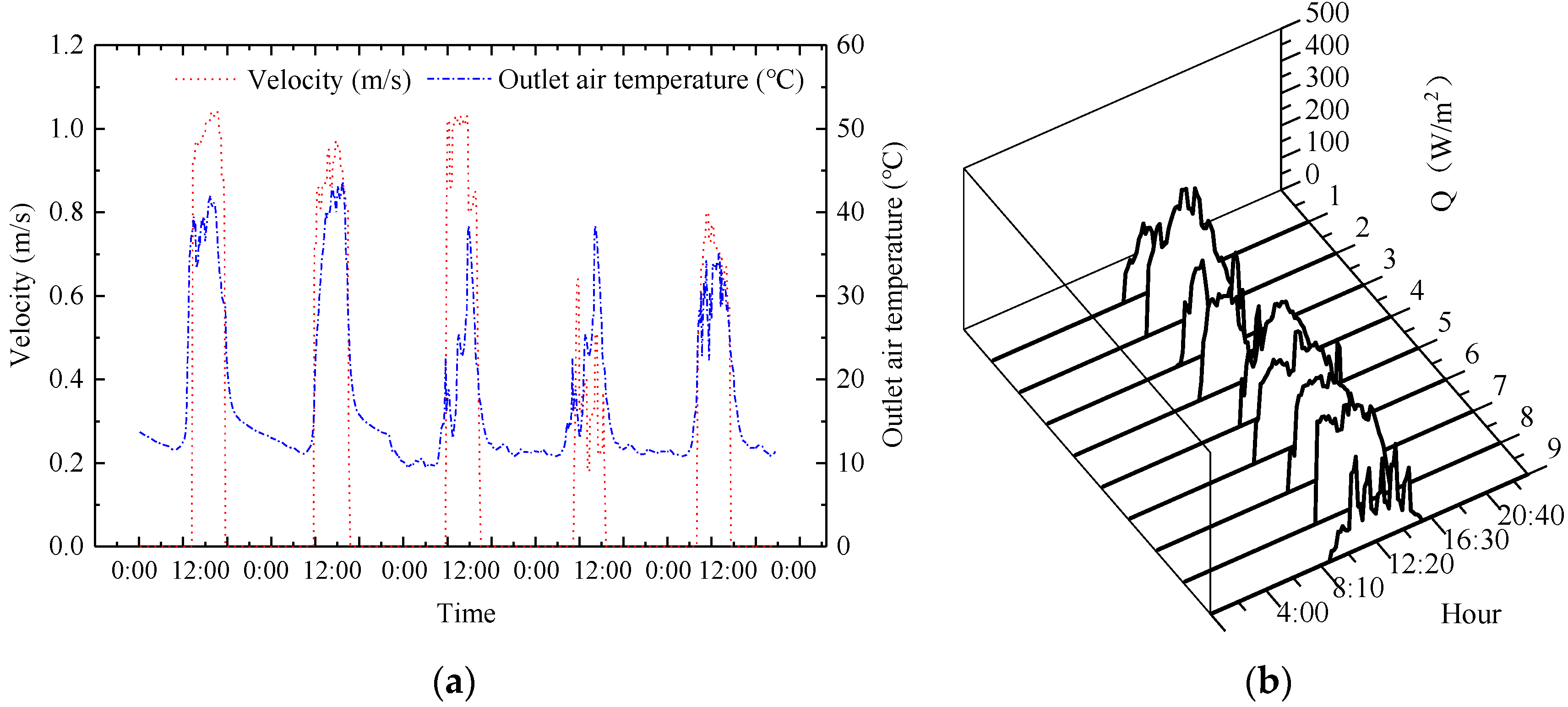
The measured outlet air temperature and air velocity of the collector are shown in Figure 7a. Based on the experimental data and equations, the heat supplied by solar walls is shown in Figure 7b, the average daily heat output of the color-changing solar wall is 1.08 MJ per unit floor area on clear days in winter. The average thermal efficiency of the solar wall is 56.8%.
The application of solar walls is mainly reflected in reducing the annual energy consumption of buildings. Taking the experimental solar house in Dalian as an example, the application effect of solar walls is quantitatively analyzed.
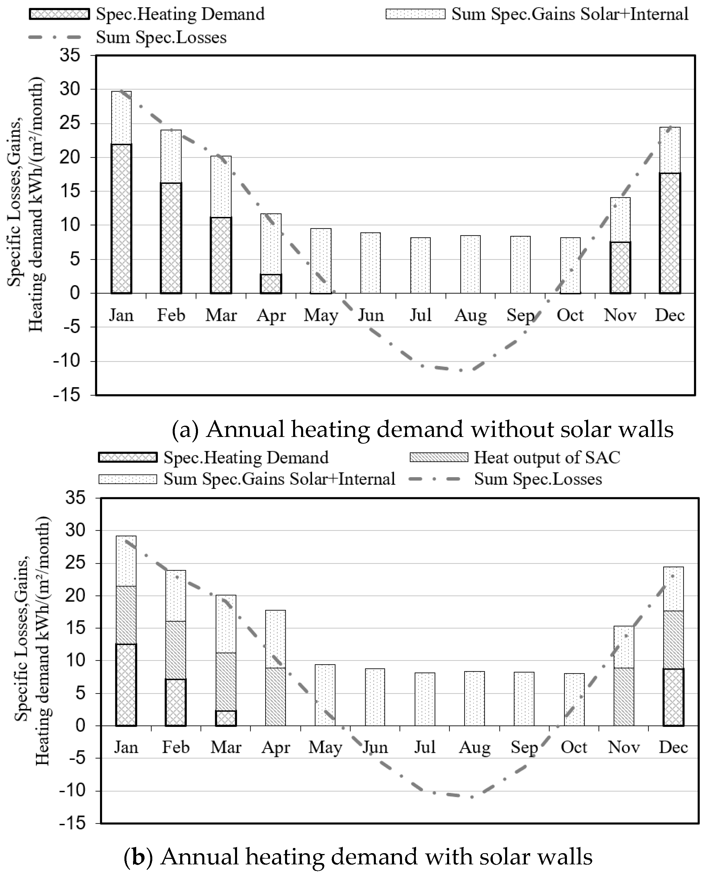
According to the climate data of Dalian and the thermal parameters of the reference building, the annual heating demand of the solar house is 466.5 MJ. Among them, the auxiliary heat source is the infrared heat radiation plate with the power of 2100 W, and the consumption of the auxiliary heat source during the heating period is 129.2 MJ. Meanwhile, the internal heat gain is 44.32 MJ. According to the average sunshine hours in winter in the Dalian area, the average heating quantity of the solar wall in the whole heating period is 145.8 MJ. The attenuation effect of solar walls on the annual heating energy consumption is shown in Figure 8.
It can be seen that the solar wall has a significant effect on reducing annual heating energy consumption. The calculation shows that the solar heating guarantee rate of the solar house is 62.8%. According to the annual energy consumption analysis, the energy-saving rate of the solar wall can reach 58.8%.
3.2. Thermal Characteristic of the Photoelectric Fan
The mass flow rate of the air gap is an important factor to determine the thermal efficiency of the color-changing solar wall. The mass flow is influenced by the air velocity, damper area and the position of the control damper. In this case, the position of the control damper is ignored and the damper is in a fixed position, with the damper open area of 0.008 m2. The influence of air temperature is also ignored. As the fan is driven by photovoltaic panels, the wind speed is an unsteady value, which is varied with the solar irradiance. Therefore, the primary factor to characterize the thermal properties of the solar wall is to determine the mass flow rate and velocity in the air gap.
The relationship between variables of fluid flow can be analyzed by dimensional analysis. The representational correlation of the average velocity of the air layer is determined based on the π theorem.
The heat transfer involving motion in the air gap is caused by the photoelectric fan and the temperature difference. Factors influencing the air velocity u include thickness of the air gap , height of the air gap H, the solar irradiance qi, the coefficient of thermal expansion , thermal conductivity , the kinematic viscosity coefficient , air density , the thermal diffusivity a and the gravitational acceleration g (Equation (3)) [36].
In the above 10 variables, the fundamental dimension number is 4. Four repeated variables are selected, respectively:
The dimensionless parameter is written by the unknown exponent, and the dimension formula is as follows.
By the dimensional harmonious Equations, the value of each coefficient is solved by:
According to Equation (6), the mathematical expression of the air velocity in the air gap is as follows,
where the modified Rayleigh number Ra* is described as follows,
Thus, the dependence of mass flow rate on the solar irradiance and channel depth can be expressed by the relationship Equation (9),
where, Re is the Reynolds number, a, b, c is the weighted coefficient, is the channel depth, m; H is the channel height, m.
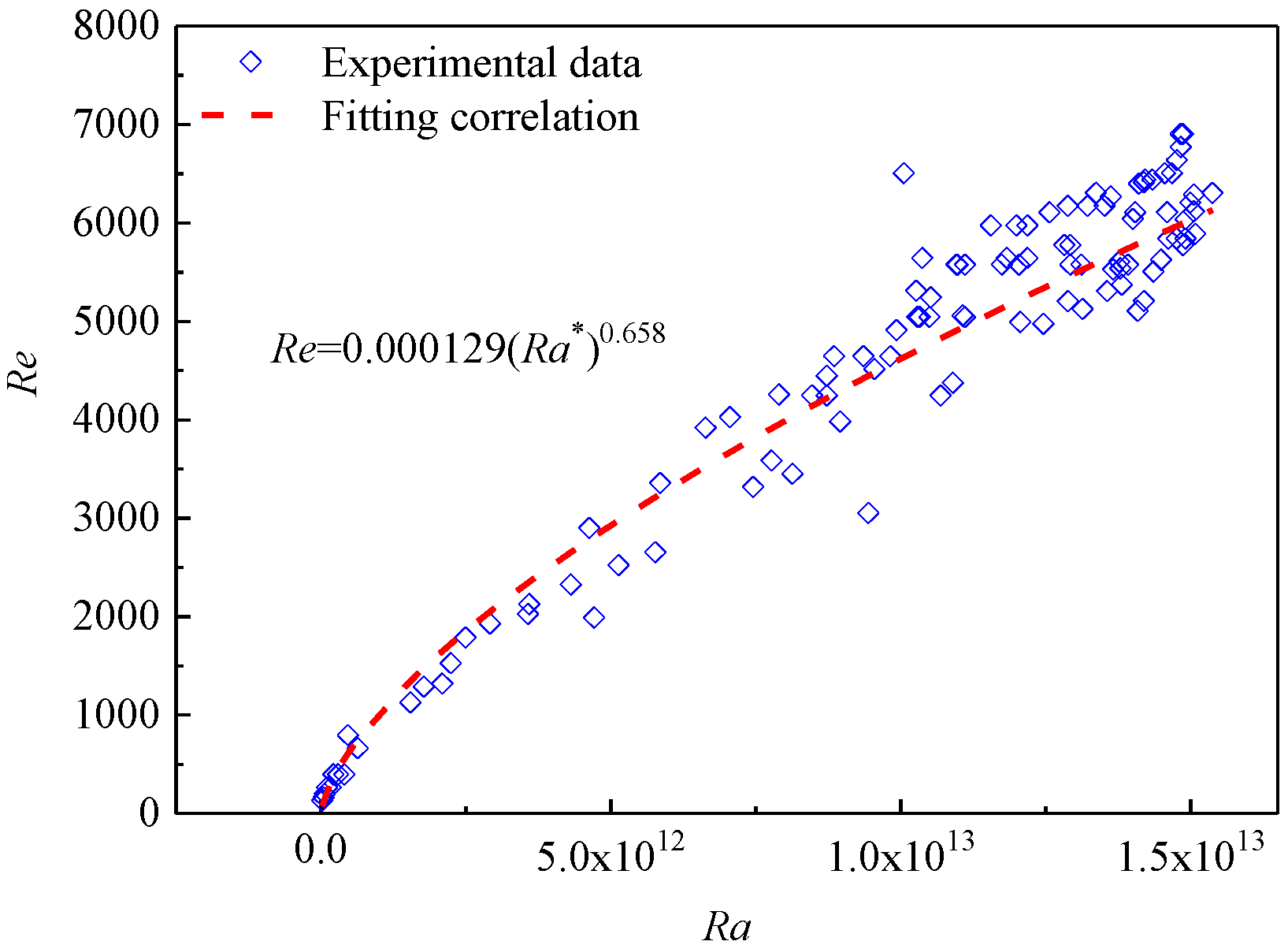
For the experimental device, the ratio is a fixed value, = 0.133. Therefore, the mass flow rate Re can be characterized as a function of heat input, as shown in Equation (10),
Based on the experimental data, the results of a multivariate regression analysis can be given in Figure 9.
Photoelectric synchronization can be achieved by the photoelectric fan and the mass flow rate in the air gap has a power function relation with the solar irradiance.
3.3. Correlation Analysis of the Temperature Control Damper
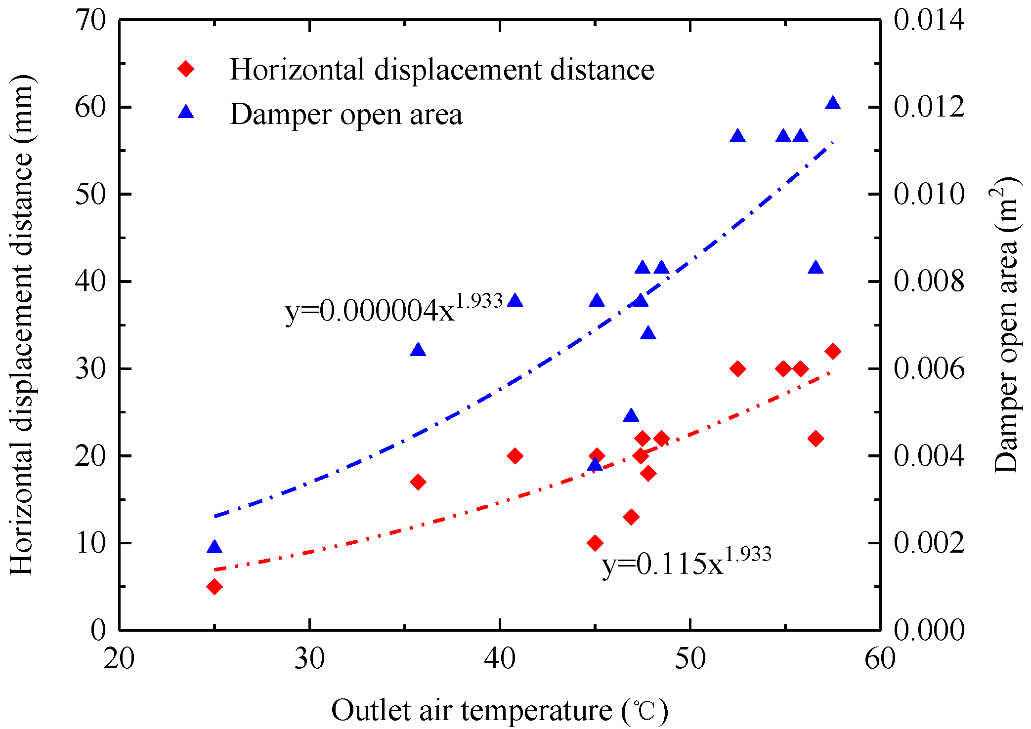
The opening degree of the damper is related to the outlet air temperature. The horizontal displacement distance and the air temperature of the outlet damper were tested for two days, and the experimental results are shown in Figure 10. As shown in Figure 10, the horizontal displacement distance of the temperature control damper is consistent with the outlet air temperature, and it increases with the outlet temperature. The distance reaches the longest when the outlet temperature reaches 60 °C, which is 32 cm. The damper is closed when the outlet temperature is lower than 20 °C. Therefore, the temperature-controlled damper can restrain the cold air inflow.
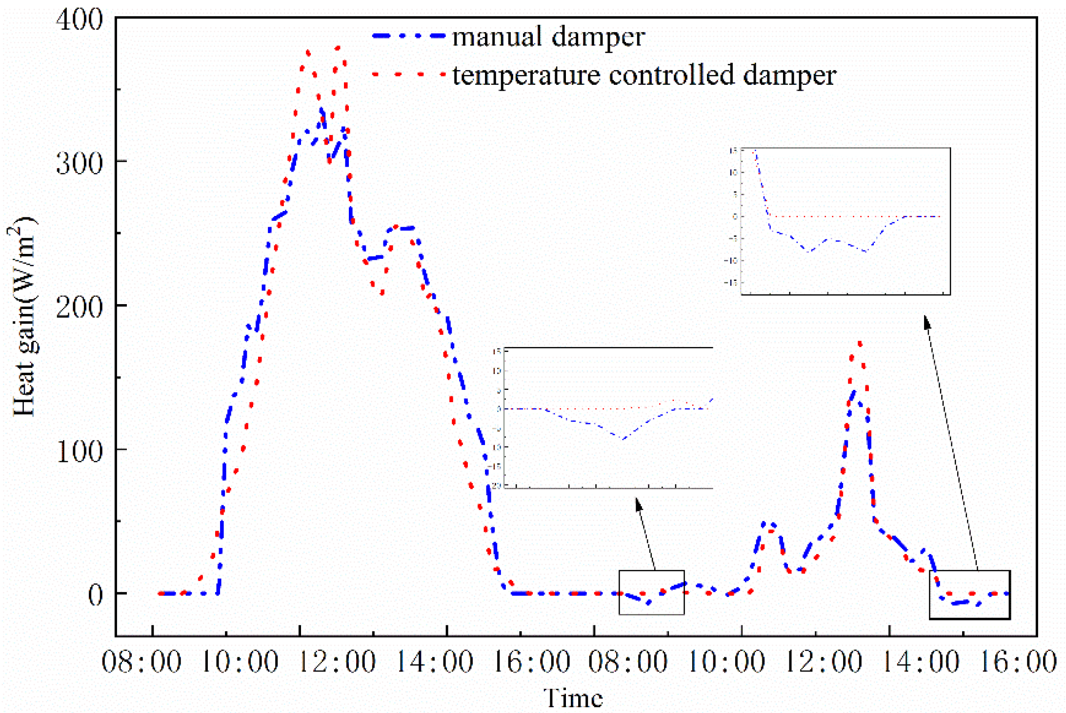
The comparison results of the heat supplied by manual damper and temperature-controlled damper are shown in Figure 11. Figure 11 indicated that from 8:00 a.m. to 9:00 a.m., a time lag of heating appeared due to the delayed opening of the manual damper. Meanwhile, between 15:30 p.m. and 17:00 p.m., due to solar radiation and other weather reasons, the air supply temperature was lower than the indoor air temperature and the artificial air door did not close in time. Therefore, the phenomenon of cold air poured backward and negative heat supply occurred. By contrast, it can be seen that the heat supplied by the temperature-controlled damper was always positive, which solved the problem of insufficient heating or reverse circulation to some extent.
4. Thermal Performance Optimization of Solar Walls
It is found that the thermal efficiency of the current solar wall is not high by the experimental analysis. Therefore, based on the numerical simulation, the structure of this solar wall is optimized in this section.
The thermal efficiency of solar walls in winter is affected by the structural dimension (aspect ratio, vent size, air channel thickness, etc.), absorber materials and curtain angle, etc. Therefore, parametric analysis was performed based on the theoretical model.
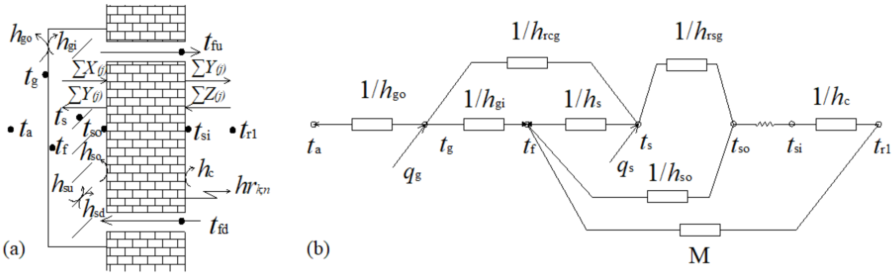
A cover, air gap, absorber plate and insulation plate formed the solar wall system. Figure 12a shows the heat transfer process of the solar wall. In the daytime, the air in the air gap is heated up by the hot absorber plate, then the indoor cold air flows into the air gap from the bottom inlet and rises to the top outlet after heating, thus completing a cycle of the heat exchange process. From the perspective of heat transfer, the heat transfer process in the solar wall is complex, involving thermal conduction, convection and radiation. The schematic diagram of the physical model is shown in Figure 12a.
A thermal network for the physical model considered is shown in Figure 12b. Through the above simplifications, combined with the thermal network model and assumption conditions [28], heat balance equations of each component of the collector can be built.
The heat balance equations from the thermal network at the points:
The values of the parameters were obtained by simulation using the MATLAB software package. According to the formulae, values of the parameters were obtained by simulation using the MATLAB software package. Experiment data on any given day were selected to verify the accuracy of the model. The values of several temperature points were obtained by simulation, and the comparison results are shown in Figure 13.
It can be seen from Figure 13 that there was a very good agreement between experimental findings and simulation results. Average deviation indices were adopted to determine errors.
- (1)
- algebraic average deviation:
- (2)
- average absolute deviation:
Table 5 shows the average deviation of three representative parameters. The good agreement observed between the simulated and experimental values verified the correctness and accuracy of the proposed model for further thermal design optimum studies.
Several factors that affect the thermal performance of the solar air collector mainly are absorber materials, structure size of the collector, such as aspect ratio, vent size, etc. Therefore, based on the mathematical model, parametric analysis about the thermal performance optimization of the solar wall system is discussed as follows.
4.1. Effect of Absorber Materials on the Thermal Performance of Solar Walls
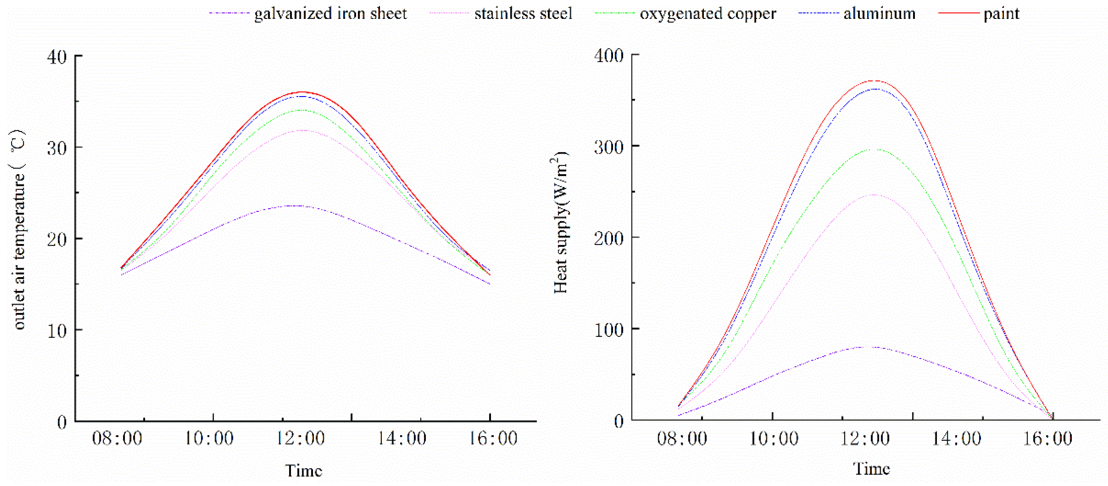
The commonly used materials for absorber boards are galvanized iron sheet, stainless steel plate, oxygenated copper, aluminum, paint and so on. The absorption rates are 0.23, 0.82, 0.65, 0.95, and 0.96 respectively within the temperature range of 20–100 °C. Figure 14 showed the thermal performance of the solar wall under various absorber materials with an aspect ratio of 2. When the material of the absorber plate was galvanized iron sheet, the outlet temperature and the heat supply were the minimum, within the range of 15−23.5 °C and 0–80 W/m2. The absorption rate of paint and aluminum was approximately equal, as was the thermal efficiency. The highest outlet air temperature reached 36 °C, and the heat supply ranged between 0–370 W/m2. Due to a number of advantages, such as low specific gravity, good thermal conductivity, less corrosion, easy processing and a relatively cheap price, aluminum is widely used as an absorber plate material. Copper is expensive. Stainless steel has some disadvantages, such as local corrosion, low thermal conductivity and large mass, etc.
4.2. Effect of Aspect Ratio on the Thermal Performance of Solar Walls
The aspect ratio is the ratio of the height and width of the solar wall, which affects the volume flow in the air layer. Under the influence of solar irradiance, the instantaneous change curves of the parameters show a cosine change. As shown in Figure 15, as the aspect ratio increased, the outlet temperature and heat supply were increasing. Therefore, the aspect ratio can be appropriately increased to improve thermal performance. However, when the aspect ratio was larger than 2, the variation range of the outlet temperature and heat supply gradually decreased, and the increasing magnitude barely changed. Therefore, in practice, an optimal aspect ratio is between 2 and 3. In addition, under the condition of a given aspect ratio, the thermal performance can be improved by increasing ventilation quantity.
4.3. Effect of Vent Size on the Thermal Performance of Solar Walls
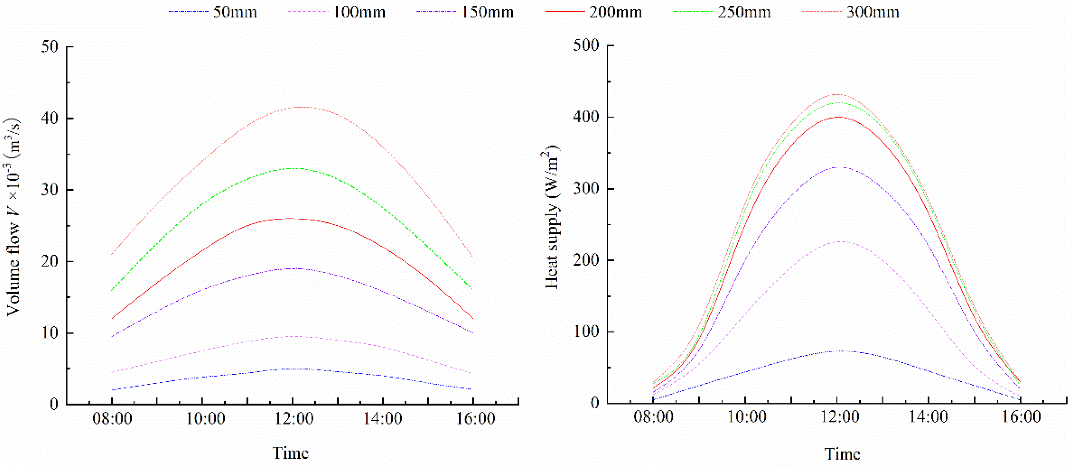
The structure size of the vent affects the volume flow in the air gap. Figure 14 shows the variation of volume flow and heat supply with the vent size. It can be seen that the volume flow of air in the channel was increased with the diameter of the vent, so as the heat supply. A larger ventilation volume can strengthen the heat transfer between the air and the absorber board, and send the heated air into the room.
According to Figure 16, the increase of vent diameter would contribute to improving thermal efficiency. However, the strengthening effect of heat supplied by the solar wall was not obvious when the vent diameter was larger than 200 mm. At the same time, the larger size of the vent may bring the inconvenience of engineering construction. Therefore, in the actual design, the ideal diameter of the vent should be about 200 mm.
5. Conclusions
To solve the problem of inconvenient manual control in the process of operation, the optimized color-changing solar wall with rotatable shutters and automatic control components was proposed in this paper. A quantitative study was conducted for improving the thermal performance of solar walls. Conclusions were drawn as follows.
- Based on the monitoring, experimental data showed that the average daily heat output of the color-changing solar wall is 1.08 MJ per unit floor area on clear days in winter and the average thermal efficiency of the solar wall is 56.8%. Furthermore, the thermal characteristic of the automatic control components was also carried out by field monitoring and theoretical analysis.
- Meanwhile, to improve the thermal performance of the solar walls system, thermal characteristic optimization analysis of the solar wall was also conducted based on the mathematical model. The structure dimensions and absorber materials were optimized. Optimization results showed that an optimal aspect ratio is between 2 and 3 and the ideal diameter of the vent is about 200 mm.
The improved solar wall with color-changing absorber board and automatic control components proposed in this paper had a positive effect on reducing building energy consumption in cold areas, which presented the theoretical basis and technical support for renewable energy utilization.
Author Contributions
Conceptualization, X.Z. and J.Z.; methodology, X.Z. and J.Z.; software, X.Z.; formal analysis, J.Z., W.L. and R.L.; investigation, R.L. and W.L.; data curation, B.C.; writing—original draft preparation, X.Z.; writing—review and editing, J.Z.; visualization, J.Z.; supervision, X.Z.; project administration, R.L. and J.Z. All authors have read and agreed to the published version of the manuscript.
Funding
This research was funded by the National Natural Science Foundation of China (No. 51808506) and Key Specialized Research and Promotion Special Project (Science and Technology Targeted) in Henan province (No. 212102310573).
Institutional Review Board Statement
Not applicable.
Informed Consent Statement
Not applicable.
Data Availability Statement
Data available on request.
Conflicts of Interest
The funders had no role in the design of the study; in the collection, analyses, or interpretation of data; in the writing of the manuscript, or in the decision to publish the results.
Nomenclature
| Symbols | |
| a | the weighed coefficient |
| A | Absorber area, m2 |
| Af | Outlet area, m2 |
| b | the weighed coefficient |
| c | the weighed coefficient |
| g | acceleration due to gravity, =9.81(m/s2) |
| G | Solar irradiance (W/m2) |
| h | heat convection (W/m2 °C) |
| H | the channel height, m |
| hc | heat convection between indoor air and interior surface (W/m2 °C) |
| hrcg | radiation heat transfer coefficient between cover plate and absorber plate (W/m2 °C) |
| hrsg | the radiation heat transfer coefficient between insulation plate and absorber plate (W/m2 °C) |
| L | length unit (m) |
| m | mass flow rate, kg/s |
| M | Mass unit (kg) |
| Pr | Prandtl number |
| q | solar radiation intensity (W/m2) |
| Ra | Rayleigh number |
| Re | Reynolds number |
| t | temperature (°C) |
| T | Unit of time(s) |
| u | air velocity, m/s |
| Subscripts | |
| a | outdoor air |
| f | air gap |
| fd/fu | inlet/outlet |
| g | cover plate |
| gi/go | interior/exterior surface of cover plate |
| out/in | outlet/inlet |
| r | indoor air |
| s | absorber plate |
| sd/su | lower/upper surface of absorber plate |
| si/so | interior/exterior surface of south wall (insulation board) |
| Greek symbol | |
| the thermal diffusivity (°C) | |
| thickness of the air gap | |
| thermal expansion coefficient (K−1) | |
| air density (kg/m3) | |
| η | Thermal efficiency |
| thermal conductivity | |
| tilt angle of the blind (°) | |
| the kinematic viscosity coefficient | |
| The dimensionless parameter | |
References
- Hernández, A.L.; Quiñonez, J.E. Experimental validation of an analytical model for performance estimation of natural convection solar air heating collectors. Renew. Energy 2018, 117, 202–216. [Google Scholar] [CrossRef]
- Bunea, M.; Perers, B.; Eicher, S.; Hildbrand, C.; Bony, J.; Citherlet, S. Mathematical modelling of unglazed solar collectors under extreme operating conditions. Sol. Energy 2015, 118, 547–561. [Google Scholar] [CrossRef]
- Ahmadi, A.; Ehyaei, M.A.; Doustgani, A.; Assad, M.E.H.; Hmida, A.; Jamali, D.H.; Kumar, R.; Li, Z.X.; Razmjoo, A. Recent residential applications of low-temperature solar collector. J. Clean. Prod. 2021, 279, 123549. [Google Scholar] [CrossRef]
- Rajarajeswari, K.; Sreekumar, A. Matrix solar air heaters—A review. Renew. Sustain. Energy Rev. 2016, 57, 704–712. [Google Scholar] [CrossRef]
- Jin, D.; Zhang, M.; Wang, P.; Xu, S. Numerical investigation of heat transfer and fluid flow in a solar air heater duct with multi V-shaped ribs on the absorber plate. Energy 2015, 89, 178–190. [Google Scholar] [CrossRef]
- Aboghrara, A.M.; Baharudin, B.; Alghoul, M.; Adam, N.M.; Hairuddin, A.A.; Hasan, H.A.; Aboghrara, A.M.; Baharudin, B.; Alghoul, M.; Adam, N.M.; et al. Performance analysis of solar air heater with jet impingement on corrugated absorber plate. Case Stud. Therm. Eng. 2017, 10, 111–120. [Google Scholar] [CrossRef]
- El-Sebaii, A.; Al-Snani, H.; El-Sebaii, A.; Al-Snani, H. Effect of selective coating on thermal performance of flat plate solar air heaters. Energy 2010, 35, 1820–1828. [Google Scholar] [CrossRef]
- Ramani, B.; Gupta, A.; Kumar, R. Performance of a double pass solar air collector. Sol. Energy 2010, 84, 1929–1937. [Google Scholar] [CrossRef]
- Omojaro, A.; Aldabbagh, L. Experimental performance of single and double pass solar air heater with fins and steel wire mesh as absorber. Appl. Energy 2010, 87, 3759–3765. [Google Scholar] [CrossRef]
- Bouadila, S.; Kooli, S.; Lazaar, M.; Skouri, S.; Farhat, A. Performance of a new solar air heater with packed-bed latent storage energy for nocturnal use. Appl. Energy 2013, 110, 267–275. [Google Scholar] [CrossRef]
- Chen, C.; Diao, Y.; Zhao, Y.; Wang, Z.; Zhu, T.; Wang, T.; Liang, L. Numerical evaluation of the thermal performance of different types of double glazing flat-plate solar air collectors. Energy 2021, 233, 121087. [Google Scholar] [CrossRef]
- Al-Damook, A.; Khalil, W.H. Experimental evaluation of an unglazed solar air collector for building space heating in Iraq. Renew. Energy 2017, 112, 498–509. [Google Scholar] [CrossRef]
- Yu, G.; Yang, H.; Yan, Z.; Ansah, M.K. A review of designs and performance of façade-based building integrated photovoltaic-thermal (BIPVT) systems. Appl. Therm. Eng. 2021, 182, 116081. [Google Scholar] [CrossRef]
- Nikolić, N.; Lukić, N. Theoretical and experimental investigation of the thermal performance of a double exposure flat-plate solar collector. Sol. Energy 2015, 119, 100–113. [Google Scholar] [CrossRef]
- Facão, J. Optimization of flow distribution in flat plate solar thermal collectors with riser and header arrangements. Sol. Energy 2015, 120, 104–112. [Google Scholar] [CrossRef] [Green Version]
- Salih, M.M.M.; Alomar, O.R.; Ali, F.A.; Abd, H.M. An experimental investigation of a double pass solar air heater performance: A comparison between natural and forced air circulation processes. Sol. Energy 2019, 193, 184–194. [Google Scholar] [CrossRef]
- Akpinar, E.K.; Koçyiğit, F. Energy and exergy analysis of a new flat-plate solar air heater having different obstacles on absorber plates. Appl. Energy 2010, 87, 3438–3450. [Google Scholar] [CrossRef]
- Ravi, R.K.; Saini, R.P. A review on different techniques used for performance enhancement of double pass solar air heaters. Renew. Sustain. Energy Rev. 2016, 56, 941–952. [Google Scholar] [CrossRef]
- Jiandong, Z.; Hanzhong, T.; Susu, C. Numerical simulation for structural parameters of flat-plate solar collector. Sol. Energy 2015, 117, 192–202. [Google Scholar] [CrossRef]
- Bahrehmand, D.; Ameri, M.; Gholampour, M. Energy and exergy analysis of different solar air collector systems with forced convection. Renew. Energy 2015, 83, 1119–1130. [Google Scholar] [CrossRef]
- Debnath, S.; Das, B.; Randive, P.; Pandey, K.M. Performance analysis of solar air collector in the climatic condition of North Eastern India. Energy 2018, 165, 281–298. [Google Scholar] [CrossRef]
- Harmim, A.; Boukar, M.; Amar, M.; Haida, A. Simulation and experimentation of an integrated collector storage solar water heater designed for integration into building facade. Energy 2019, 166, 59–71. [Google Scholar] [CrossRef]
- Şevik, S.; Abuşka, M. Thermal performance of flexible air duct using a new absorber construction in a solar air collector. Appl. Therm. Eng. 2019, 146, 123–134. [Google Scholar] [CrossRef]
- Alta, D.; Bilgili, E.; Ertekin, C.; Yaldiz, O. Experimental investigation of three different solar air heaters: Energy and exergy analyses. Appl. Energy 2010, 87, 2953–2973. [Google Scholar] [CrossRef]
- Karsli, S. Performance analysis of new-design solar air collectors for drying applications. Renew. Energy 2007, 32, 1645–1660. [Google Scholar] [CrossRef]
- Chow, T.T. A Review on Photovoltaic/Thermal Hybrid Solar Technology. Renew. Energy 2010, 87, 88–119. [Google Scholar] [CrossRef]
- Yeh, H.M.; Ho, C.D. Effect of external recycle on the performance of flat plate solar air heaters with internal fins attached. Renew. Energy 2009, 34, 1340–1347. [Google Scholar] [CrossRef]
- Youcef-Ali, S. Study and optimization of the thermal performances of the offset rectangular plate fin absorber plates with various glazing. Renew. Energy 2005, 30, 271–280. [Google Scholar] [CrossRef]
- Badescu, V.; Soriga, I.; Ciocanea, A. Solar air collector performance in transient operation under radiative regimes with different levels of stability. Sol. Energy 2019, 177, 200–212. [Google Scholar] [CrossRef]
- Li, G.; Huang, H.; Zhang, J.; Zhang, H. Study on the performance of a solar collector with heat collection and storage. Appl. Therm. Eng. 2019, 147, 380–389. [Google Scholar] [CrossRef]
- Zhang, H.; Ma, X.; You, S.; Wang, Y.; Zheng, X.; Ye, T.; Zheng, W.; Wei, S. Mathematical modeling and performance analysis of a solar air collector with slit-perforated corrugated plate. Sol. Energy 2018, 167, 147–157. [Google Scholar] [CrossRef]
- Zhu, J.; Chen, B. A Mathematic Model of a Color-changed Passive Solar House. Energy Procedia 2017, 105, 1009–1014. [Google Scholar] [CrossRef]
- Nikolić, N.; Lukić, N. A mathematical model for determining the optimal reflector position of a double exposure flat-plate solar collector. Renew. Energy 2013, 51, 292–301. [Google Scholar] [CrossRef]
- Deng, J.; Ma, R.; Yuan, G.; Chang, C.; Yang, X. Dynamic thermal performance prediction model for the flat-plate solar collectors based on the two-node lumped heat capacitance method. Sol. Energy 2016, 135, 769–779. [Google Scholar] [CrossRef]
- Zheng, W.; Li, B.; Zhang, H.; You, S.; Li, Y.; Ye, T. Thermal characteristics of a glazed transpired solar collector with perforating corrugated plate in cold regions. Energy 2016, 109, 781–790. [Google Scholar] [CrossRef]
- Wu, D.; Aye, L.; Ngo, T.; Mendis, P. Optimisation and financial analysis of an organic Rankine cycle cooling system driven by facade integrated solar collectors. Appl. Energy 2017, 185, 172–182. [Google Scholar] [CrossRef]
- Long, L.; Ye, H.; Liu, M. A new insight into opaque envelopes in a passive solar house: Properties and roles. Appl. Energy 2016, 183, 685–699. [Google Scholar] [CrossRef]
- Liu, Y.; Wang, D.; Ma, C.; Liu, J. A numerical and experimental analysis of the air vent management and heat storage characteristics of a trombe wall. Sol. Energy 2013, 91, 1–10. [Google Scholar] [CrossRef]
- Sun, C.; Liu, Y.; Duan, C.; Zheng, Y.; Chang, H.; Shu, S. A mathematical model to investigate on the thermal performance of a flat plate solar air collector and its experimental verification. Energy Convers. Manag. 2016, 115, 43–51. [Google Scholar] [CrossRef]
- Burek, S.; Habeb, A. Air flow and thermal efficiency characteristics in solar chimneys and Trombe Walls. Energy Build. 2007, 39, 128–135. [Google Scholar] [CrossRef]
- Coakley, D.; Raftery, P.; Keane, M. A review of methods to match building energy simulation models to measured data. Renew. Sustain. Energy Rev. 2014, 37, 123–141. [Google Scholar] [CrossRef] [Green Version]
- Elguezabal, P.; Lopez-Dominguez, A.; Blanco, J.; Chica, J. CFD model-based analysis and experimental assessment of key design parameters for an integrated unglazed metallic thermal collector façade. Renew. Energy 2020, 146, 1766–1780. [Google Scholar] [CrossRef] [Green Version]
- Zhu, J.; Chen, B. Simplified analysis methods for thermal responsive performance of passive solar house in cold area of China. Energy Build. 2013, 67, 445–452. [Google Scholar] [CrossRef]
- Zhu, J.; Chen, B. Experimental study on thermal response of passive solar house with color changed. Renew. Energy 2015, 73, 55–61. [Google Scholar] [CrossRef]
Figure 1.
Operation principle (a) in winter (b) in summer. Reprinted with permission from ref. [43]. Copyright 2021 Elsevier.
Figure 1.
Operation principle (a) in winter (b) in summer. Reprinted with permission from ref. [43]. Copyright 2021 Elsevier.

Figure 2.
A photo of the full-scale experimental house (a) in winter (b) in summer.

Figure 3.
Diagram of PV board and fan.

Figure 4.
The photo and operation principle of temperature-controlled damper.

Figure 5.
Schematic diagram of measuring point arrangement in the passive solar house.

Figure 6.
Variation of indoor air temperature in the passive solar house.

Figure 7.
(a) Outlet air temperature and air velocity of the collector (b) Heat output of the solar wall.
Figure 7.
(a) Outlet air temperature and air velocity of the collector (b) Heat output of the solar wall.

Figure 8.
Annual heating demand under solar walls heating.

Figure 9.
The relationship of Re and Ra.

Figure 10.
The relationship between the outlet temperature and damper displacement distance.

Figure 11.
The heat gain comparison of different dampers.

Figure 12.
Heat transfer process (a) and thermal network model (b) of the solar wall.

Figure 13.
Validation of simulation results under passive heating.

Figure 14.
Effect of fin material on outlet temperature and heat gain of the solar wall.

Figure 15.
Effect of shape ratio on outlet temperature and heat gain of the solar wall.

Figure 16.
Effect of vent size on volume flow and heat gain of the solar wall.


Table 1.
Investigations on thermal performance of different types of solar air collectors.
| Author | Types | Diagram | Inference |
|---|---|---|---|
| D. Jin et al. [5] | solar air heater duct having multi V-shaped ribs on the absorber plate |  | The maximum value of the thermal performance parameter was 1.93 for the range of parameters investigated. |
| A.M. Aboghrara et al. [6] | solar air heater with jet impingement on corrugated absorber plate |  | The thermal efficiency of proposed design duct is observed almost 14% more as compared to the smooth duct. |
| A.A. El-Sebaii, H. Al-Snani [7] | flat plate solar air heaters-double pass flat and v-corrugated plate |  | The annual average of a nickel–tin selectively coated absorber is higher than that with a black painted absorber by 29.23%. |
| B.M. Ramani et al. [8] | double pass solar air collector with and without porous material |  | Thermal efficiency of double pass solar air collector with porous absorbing material is 20–25% higher than that of collector without porous absorbing material. |
| A.P. Omojaro et al. [9] | a double pass solar air heater with fins attached and using a steel wire mesh as absorber plate |  | The efficiency of the double pass is found to be higher than the single pass by 7–19.4%. |
| S. Bouadila et al. [10] | a solar air heater with packed-bed latent storage energy |  | The daily energy efficiency varied between 32% and 45%. While the daily exergy efficiency varied between 13% and 25%. |
| C.Q. Chen et al. [11] | double glazing flat-plate solar air collectors |  | The efficiency factor and total heat loss coefficient of Model 4 are 0.62707 and 2.21745, respectively. |
Table 2.
Building information.
| Floor Area/m2 | The Ratio of Window to Wall in South Façade/% | Shape Coefficient | SHGC of Windows | Heat Transfer Coefficient (W/m2·°C) | |||
|---|---|---|---|---|---|---|---|
| External Walls | Floor | Roof | Window | ||||
| 75 | 21.2 | 0.468 | 0.43 | 0.42 | 0.48 | 0.45 | 2.1 |
Table 3.
Building envelope construction.
| Layer | Construction |
|---|---|
| External walls | 20 mm plaster + 370 mm solid brick + 70 mm polystyrene board |
| Internal walls | 240 mm solid brick |
| Floor | 50 mm wood floor + 50 mm poured concrete + 100 mm loess + 50 mm polystyrene board |
| Roof | 20 mm plaster + 200 mm steel concrete + 50 mm polystyrene board + 20 mm tile |
| window | double glazing + aluminum alloy window frames |
Table 4.
Dimensions of the solar wall system.
| Parameter | Dimensions | Parameter | Dimensions |
|---|---|---|---|
| Collectors tilt angle | 90 | Plate thickness | 3 mm |
| Absorber surface area | 1.05 m2 | Glass emissivity | 0.9 |
| Thickness of air gap | 300 mm | Absorber plate emissivity | 0.4 |
| Thickness of insulation | 3 mm | Glass transmissivity | 0.85 |
| Air duct diameter | 100 mm | Absorber absorptivity | 0.9 |
| Glass cover thickness | 1 mm | Ratio between the solar wall and the floor area | 0.23 |
Table 5.
Monitored data and technical specification of measuring instruments.
| Monitored Parameters | Instrument Name | Accuracy | Photos |
|---|---|---|---|
| Surface temperature and heat flow | JTNT-B Temperature test system | ±0.1 °C ±0.01 W/m2 |  |
| Air temperature and relative humidity | TR-72U Temperature and humidity recorder | ±0.1 °C ±1% |  |
| Solar irradiance Air temperature and relative humidity | E-log Outdoor weather station | ±1 W/m2 ±0.01 m/s ±0.1 °C |  |
| Air velocity | KANOMAX-6004 Hot-wire anemometer | ±0.01 m/s |  |
| temperature field | FLIR T440 Infrared thermal imager | ±1 °C |  |
Table 6.
Difference between the measured value and simulated value.
| The Average Deviation | Interface Temperature of South Wall | Outlet Temperature | Indoor Air Temperature |
|---|---|---|---|
| 10.5% | 11.7% | 5.4% | |
| 12.7% | 14.3% | 6.4% |
Publisher’s Note: MDPI stays neutral with regard to jurisdictional claims in published maps and institutional affiliations. |
© 2021 by the authors. Licensee MDPI, Basel, Switzerland. This article is an open access article distributed under the terms and conditions of the Creative Commons Attribution (CC BY) license (https://creativecommons.org/licenses/by/4.0/).
Share and Cite
MDPI and ACS Style
Zhao, X.; Zhu, J.; Li, R.; Li, W.; Chen, B. Thermal Characteristics and Parametric Analysis of an Improved Solar Wall. Appl. Sci. 2021, 11, 6325. https://doi.org/10.3390/app11146325
AMA Style
Zhao X, Zhu J, Li R, Li W, Chen B. Thermal Characteristics and Parametric Analysis of an Improved Solar Wall. Applied Sciences. 2021; 11(14):6325. https://doi.org/10.3390/app11146325
Chicago/Turabian StyleZhao, Xi, Jiayin Zhu, Ruixin Li, Weilin Li, and Bin Chen. 2021. "Thermal Characteristics and Parametric Analysis of an Improved Solar Wall" Applied Sciences 11, no. 14: 6325. https://doi.org/10.3390/app11146325
Note that from the first issue of 2016, this journal uses article numbers instead of page numbers. See further details here.