Article

Integrated Control and Protection Architecture for Islanded PV-Battery DC Microgrids: Design, Analysis and Experimental Verification

1
Department of Electrical Engineering, Faculty of Engineering, University of Zanjan, Zanjan 45371-38791, Iran
2
CROM Center for Research on Microgrids, Department of Energy Technology, Aalborg University, 9220 Aalborg, Denmark
*
Author to whom correspondence should be addressed.
Appl. Sci. 2020, 10(24), 8847; https://doi.org/10.3390/app10248847
Submission received: 26 November 2020 / Revised: 5 December 2020 / Accepted: 7 December 2020 / Published: 10 December 2020

Abstract

:
Direct current (dc) microgrids have gained significant interest in research due to dc generation/storage technologies—such as photovoltaics (PV) and batteries—increasing performance and reducing in cost. However, proper protection and control systems are critical in order to make dc microgrids feasible. This paper aims to propose a novel integrated control and protection scheme by using the state-dependent Riccati equation (SDRE) method for PV-battery based islanded dc microgrids. The dc microgrid under study consists of photovoltaic (PV) generation, a battery energy storage system (BESS), a capacitor bank and a dc load. The aims of this study are fast fault detection and voltage control of the dc load bus. To do so, the SDRE observer-controller—a nonlinear mathematical model—is employed to model the operation of the dc microgrid. Simulation results show that the proposed SDRE method is effective for fault detection and robust against external disturbances, resulting in it being capable of controlling the dc load bus voltage during disturbances. Finally, the dc microgrid and its proposed protection scheme are implemented in an experimental testbed prototype to verify the fault detection algorithm feasibility. The experimental results indicate that the SDRE scheme can effectively detect faults in a few milliseconds.

1. Introduction

In recent years, the microgrid has become more attractive, because of its ability to meet increasing energy demands in a greener way. The components of a microgrid include distributed renewable energy resources (such as photovoltaics (PV), wind and hydel, etc.) and energy storage systems (e.g., battery bank, flywheel, supercapacitor) which deliver power to local loads [1,2]. In the microgrid concept, the energy storage device plays a key role in the demand–supply balance, which helps during islanding and re-synchronizing between the utility grid and microgrid [3]. Thus, it can tackle the energy crisis, and improve grid efficiency. The microgrid includes a dc microgrid, an ac microgrid, and an ac/dc hybrid microgrid. Among them, the direct current (dc) microgrids are more technically superior than the ac ones because of the lack of a skin effect, less corona loss, less conductor stress, and simple control mechanisms. The dc microgrid can lead to low power quality problems in the utility grid. For such a system, there are absences of harmonics, reactive power, and frequency regulation, but when dealing with an ac system such issues might arise [4]. However, the absence of a feasible method, standards and guidelines still exist for dc microgrid protection and control. Therefore, this paper analyses the protection and voltage control of islanded dc microgrids with photovoltaics (PV) and energy storage.
Dc microgrids possess plenty of merits compared to classical ac ones. Lower converter requirements, a higher transmission capacity, higher power quality, power transmission loss reductions and a negligible skin effect represent the merits of the dc microgrids over ac networks [3,4,5,6,7,8,9]. Despite their remarkable merits, dc microgrid protection poses many challenges [7,8,9,10,11,12]. Familiarity with fault detection in microgrids allows for quick restoration, maintenance and decreases in unnecessary power outage periods [6,7,8,9,10]. In [10], a multi-layer perceptron neural network-based fault location technique has been proposed for a loop-type dc microgrid system. In [11], a simultaneous protection and control procedure for a multi dc microgrid configuration is proposed. This research attempted to propose a unified procedure regarding protection and control. The enforceability of the proposed method was validated via a prototype experimental circuit. In [12], a fast multi-rules and neural network-based protection scheme has been presented based on a ring-type dc microgrid configuration. The proposed multi-rules protective system was used for fast fault detection, at the same time, the neural network-based protective system acted as a secondary and ancillary system that predicts the accurate location of the fault incidence.
A protection approach based on the events for a dc system was proposed in [13]. The propounded protection scheme brings less data transfer than the prevalent data-based protection strategy. In [14], a differential-based protection approach was recommended for dc networks, which was able to detect faults in sub-milliseconds. This research employed the inherent specifications of dc differential current values in order to achieve a remarkable reduction in the time required for fault detection compared to other approaches. In [15], a differential-based protection procedure in mesh-type dc microgrids was proposed. This method employed a specific threshold for fault detection. The trouble of threshold selection is the issue of differential-based protection in the dc microgrid system. Obviously, the time of fault detection of the differential-based procedure is completely affiliated with the threshold value selection, the time window selection, protection algorithm complexity, and communication delay. An increase or decrease in the threshold value increases or decreases the fault detection time, which is a major problem in differential protection as it has a completely direct relationship with the time of fault detection. Additionally, there are no standards, solutions, or published experiences in dc grids, leading to problems in selecting the threshold value in the differential method. Hence, this value is specified by the microgrid structure and operator’s experience, which is the major bug of this approach, that is, the protection algorithm depends on human action and considerations.
In [16], the use of the linear observer for transmission line protection has been investigated in ac microgrids. Merits and drawbacks of this method include the fast fault detection and lack of robustness to disturbances, respectively. The use of the linear observer with minimum sensors for lines and transformer protection has been presented in [17]. For instance, in [18] a state-dependent Riccati equation (SDRE) non-linear observer was used for fault detection in wind turbines. This paper recommends a structure for the design of a nonlinear observer via a state-dependent differential Riccati equation (SDDRE) instead of algebraic Riccati equations that can require an excessively restrictive necessity for system visibility and manageability. Via expanded linearization of the dynamics procedures, the SDDRE and a solution of SDRE could be determined via utilizing the numerical unification approaches. The obtained results in [16,17,18] demonstrate the ability to use a linear and nonlinear observer to detect faults in microgrids.
The observer-based methods can also be used for fault detection in the microgrids. Unlike conventional protection, there is no need for an adaptive protection system that needs to adapt to network changes and variations. The current research presents a novel approach for fault detection based on an SDRE nonlinear observer-controller to accommodate the characteristics of an SDRE observer-controller and nonlinear dynamics of dc microgrids. This method shows suitable speed and accuracy, can detect faults and is robust against disturbances. To verify the capability and the conceivability of the proposed protection scheme, the simulated circuit and fault detection procedures are fulfilled and examined at a prototype laboratory size.

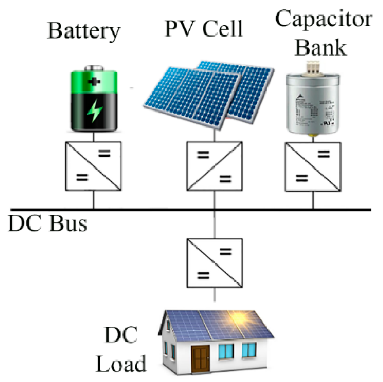
2. Proposed PV-Battery Islanded DC Microgrid

The schematic of the PV-battery islanded dc microgrid configuration, as a studied network, is shown in Figure 1. This dc microgrid consists of a PV system, a dc load, a battery energy storage system (BESS), and a capacitor bank. In this dc microgrid, a PV system is connected via a dc-dc converter to the dc bus. In addition, a battery and capacitor bank are connected to the dc bus through a dc-dc converter for operating the islanding mode of the system, and a dc variable resistive load is connected directly to the bus bar to model the dc system load. During the operation of the microgrid, the PV power generation changes alternately throughout the day. The management plan of the dc microgrid in the islanding mode is such that if the PV system’s power generation is greater than the power consumption, the battery and capacitor bank begin to charge and the additional power is used to balance the system. Otherwise, if the PV system’s power generation is less than power consumption, the energy storage is discharged and, as a result, the microgrid voltage remains constant [19].
The proposed dc microgrid is designed to withstand heavy disturbances. In addition, at every moment of operation, the capacity of the dc microgrid should be such that it feeds the load. For these reasons, in the design of the dc microgrid, two energy storage devices such as BESS and capacitor bank have been employed. The details of dc microgrid modeling are shown in Figure 2, and their parameters and mathematical relations are presented as follows.

2.1. PV System, Battery and Capacitor Bank Modeling

According to Figure 2, the PV system is connected to a dc bus via a dc-dc converter. The measured variables are I L 3 ( t ) ,   V C 1 ( t ) and V C 2 ( t ) , that are the L3 inductor current, and the C1 and C2 capacitors voltage, respectively. The control input 1 u 1 ( t ) 1 is a voltage, to control the output voltage of the PV system. The battery is also connected to a dc bus through a dc-dc converter. The measured variables are I L 6 ( t ) , V C 4 ( t ) and V C 5 ( t ) , that are L6 inductor current, C4 and C5 capacitors voltage, respectively. The control input 1 u 2 ( t ) 1 is also a voltage, to control the battery output voltage. The capacitor bank is also connected to a dc bus through a dc-dc converter. The measured variables are I L 8 ( t ) and V C 7 ( t ) , that are L8 current and C7 voltage, respectively. The control input 1 u 3 ( t ) 1 is also a voltage to control the output voltage of the capacitor bank.

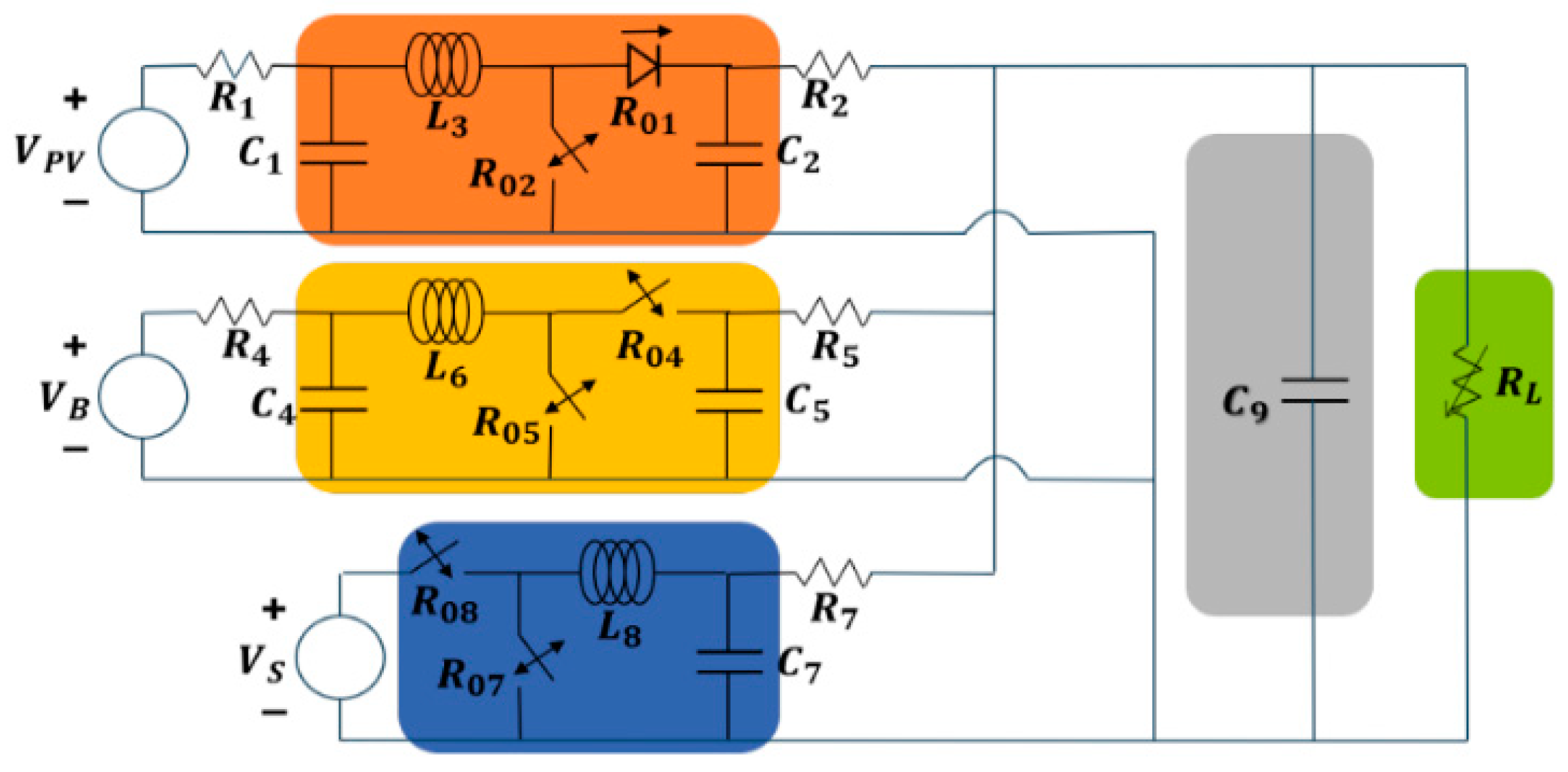
2.2. DC Microgrid Modeling

By defining the following state variables: x 1 = V C 1 ,   x 2 = V C 2 ,   x 3 = I L 3 ,   x 4 = V C 4 ,   x 5 = V C 5 , x 6 = I L 6 ,   x 7 = V C 7 ,   x 8 = I L 8 , x 9 = V C 9 the representation of the state space is as follows [19].
x ˙ 1 = 1 R 1 C 1 x 1 1 C 1 x 3 1 R 1 C 1 V P V x ˙ 2 = 1 R 2 C 2 x 2 + 1 C 2 x 3 + 1 C 2 u 1 x 3 1 R 1 C 1 V P V   x ˙ 3 = 1 L 3 ( x 1 x 2 R 01 x 3 ) + 1 L 3 ( x 2 + ( R 01 R 02 ) u 1 ) x ˙ 4 = 1 R 4 C 4 x 4 + 1 C 4 x 6 1 R 4 C 4 V B x ˙ 5 = 1 R 5 C 5 x 5 1 C 5 x 6 1 C 5 u 2 x 5 + 1 R 5 C 5 x 9 x ˙ 6 = 1 L 6 ( x 4 x 5 R 04 x 6 + u 2 x 5 ) x ˙ 7 = 1 R 7 C 7 x 7 1 C 7 x 8 + 1 R 7 C 7 x 9 x ˙ 8 = 1 L 8 ( u 3 V s R 08 x 8 x 7 ) x ˙ 9 = 1 C 9 ( x 2 x 9 R 2 + x 5 x 9 R 5 + x 7 x 9 R 7 x 9 R L )
The parameters of the employed model are given in Table 1 [19].

3. Proposed SDRE Nonlinear Observer-Controller

In this Section, a brief review of the designing of the SDRE nonlinear controller-observer is stated.

3.1. SDRE Controller

Assume the following nonlinear system:
x ˙ ( t ) = f ( x ( t ) ) + B ( x ( t ) ) u ( t ) ,       x ( 0 ) = x 0
That x ( t ) R n is the state vector, u ( t ) R m is the control input and x 0 is an initial condition. f ( x ( t ) )   :   R n   R n and B ( x ( t ) ) : R n   R n × m are two known functions of system states. We assume that this system has an equilibrium at the origin point, and therefore, the main idea used in SDRE is to show this nonlinear system in a quasi-linear manner [20]. That way, the factorization is performed as f ( x ( t ) ) = A ( x ( t ) ) x ( t ) that, A ( x ( t ) )   : R n     R n × n is a state-dependent matrix. A remarkable point in this factorization is the numerous possibilities for decomposing f ( x ( t ) ) as a coefficient of   x ( t ) . For example, if the function f ( x ( t ) ) is f ( x ( t ) ) = A 1 ( x ( t ) ) x ( t ) and f ( x ( t ) ) = A 2 ( x ( t ) ) x ( t ) , then any other linear combination of   A 1 ( x ( t ) ) and   A 2 ( x ( t ) ) also forms an alternate linear structure in A ( x ( t ) ) = α ( x ( t ) ) A 1 ( x ( t ) ) + ( 1 α ( x ( t ) ) A 2 ( x ( t ) ) , in which α ( x ( t ) ) is a definite function of x ( t ) . This issue is one of the advantages of the SDRE method, which provides the designer with an extra degree of freedom. In designing an optimal stabilizer, the aim is to find a control rule by which it can bring the system states to the equilibrium point at the system origin, see Equation (1), and minimize the predetermined cost function below [20]:
J = 1 2 0 ( x T ( t ) Q ( x ( t ) ) x ( t ) + u T ( t ) R ( x ( t ) ) u ( t ) ) d t
which in R ( x ( t ) )   : R n     R m × m and Q ( x ( t ) )   : R n     R n × n are the state dependent weighting matrices and are, respectively, a positive and a positive-semidefinite integrand point. The solution of the optimal control problem described by Equations (1) and (2) requires the finding of the Hamilton Jacobi Bellman equation (HJB) [20]. On the other hand, this HJB equation is very complex in general. In the SDRE method, it is shown that one can use the control rule u to find an approximate solution to this optimal control problem, in which the matrix β is the definite unique positive solution of the SDRE based on the following statement:
A T ( x ( t ) ) P ( x ( t ) ) + P ( x ( t ) ) A ( x ( t ) ) P ( x ( t ) ) B ( x ( t ) ) R 1 ( x ( t ) ) B T ( x ( t ) ) P ( x ( t ) ) + Q ( x ( t ) ) = 0
The most important point is that Equation (4) has a definite unique positive symmetric solution if and only if pairs ( A ( x ( t ) ) , B ( x ( t ) ) ) and ( A ( x ( t ) ) , Q 1 2 ( x ( t ) ) ) are point-to-point stable and point-to-point observer, respectively. In [20] it is shown that the equilibrium in the closed-loop system caused by the SDRE controller is local asymptotically stable.

3.2. SDRE Observer

Consider the following nonlinear system:
x ˙ ( t ) = f ( x ( t ) ) + B ( x ( t ) ) u ( t ) ,     x ( 0 ) = x 0 y ( t ) = h ( x ( t ) )
That y q is system output, h ( x ( t ) )   :   R n   R n × q is known as a function of the system state. The problem is to estimate the x ( t ) state vector assuming the measurement of y ( t ) . If x ( t ) estimation is shown as x ^ ( t ) , according to theorem one in [21], the estimation error e ( t ) = x ( t ) x ^ ( t ) generated by the SDRE observer asymptotically tends to be zero. The structure of the SDRE observer is as follows:
x ^ ˙ ( t ) = A ( x ^ ( t ) ) x ^ ( t ) + B ( x ^ ( t ) ) u ( t ) + L ( x ^ ( t ) ) ( y ( t ) C ( x ^ ( t ) ) x ^ ( t ) )
in which f ( x ^ ( t ) ) = A ( x ^ ( t ) ) x ^ ( t ) , h ( x ^ ( t ) ) = C ( x ^ ( t ) ) x ^ ( t ) and L ( x ^ ( t ) ) are observer gains, which are obtained from equation L ( x ^ ( t ) ) = Σ ( x ^ ( t ) ) C T ( x ^ ( t ) ) V 1 . In this case Σ ( x ^ ( t ) ) , the solution of the Riccati equation depends on the following condition.
A ( x ^ ( t ) ) Σ ( x ^ ( t ) ) + Σ ( x ^ ( t ) ) A T ( x ^ ( t ) )   Σ ( x ^ ( t ) ) C T ( x ^ ( t ) ) V 1 C ( x ^ ( t ) ) Σ ( x ^ ( t ) ) + W = 0
According to theorem one in [21], in order to reach the stable SDRE observer, it is necessary that the pair ( A T ( x ^ ( t ) ) , C T ( x ^ ( t ) ) ) is stable at all points for all x ^ ( t ) R n . The weight matrices V R q × q and W R n × n are symmetric and determined by the designer. It should be noted that V and W are, respectively, positive-semidefinite integrand point and positive, respectively. It should be noted that the purpose of the SDRE observer’s stability is that the estimation error e ( t ) asymptotically tends to zero.

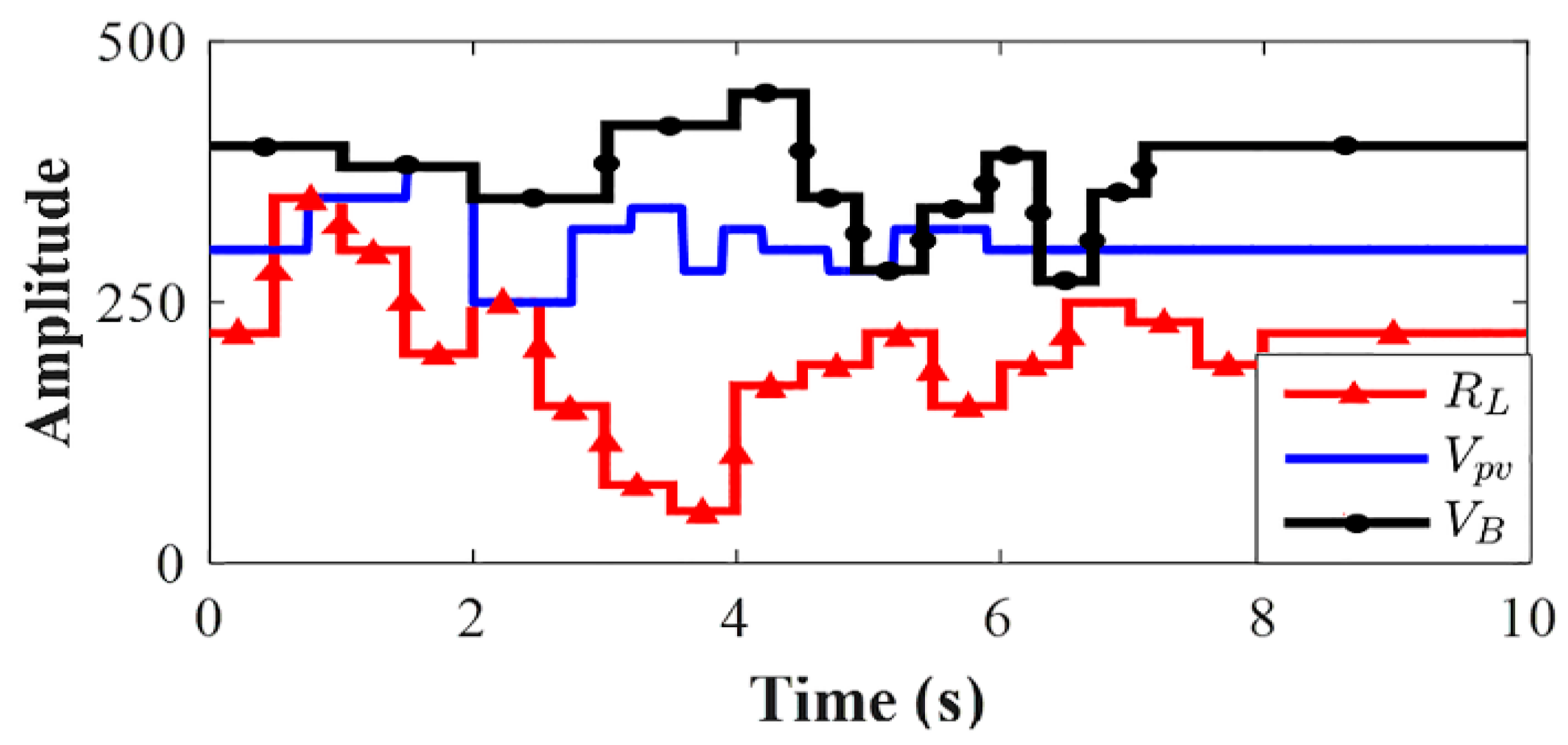
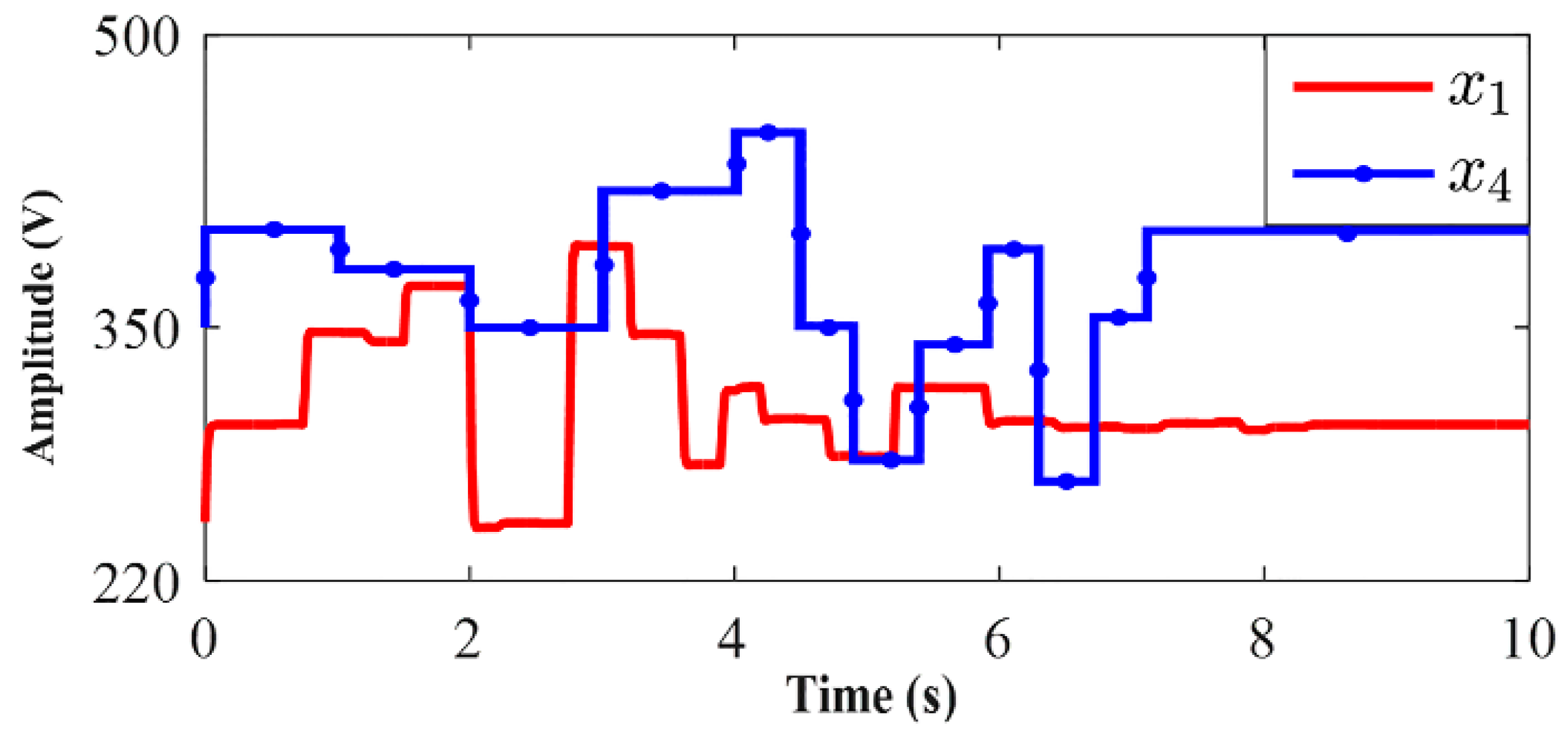
4. Simulation Results

This section shows the simulation results divided into two parts. The first part gives the results of the control of the output voltage of the PV system, battery, capacitor bank and dc bus in the presence of parameter uncertainty using an SDRE controller. The second part is dedicated to analyzing the results of the SDRE observer for fast fault detection. The studied microgrid with a protection system based on the SDRE controller is simulated in MATLAB/Simulink software via the “Ode23tb (stiff/TR-BDF2)” solver, with the variable-step sampling, maximum step size is 10−4, and automatic minimum step size.

4.1. SDRE Controller
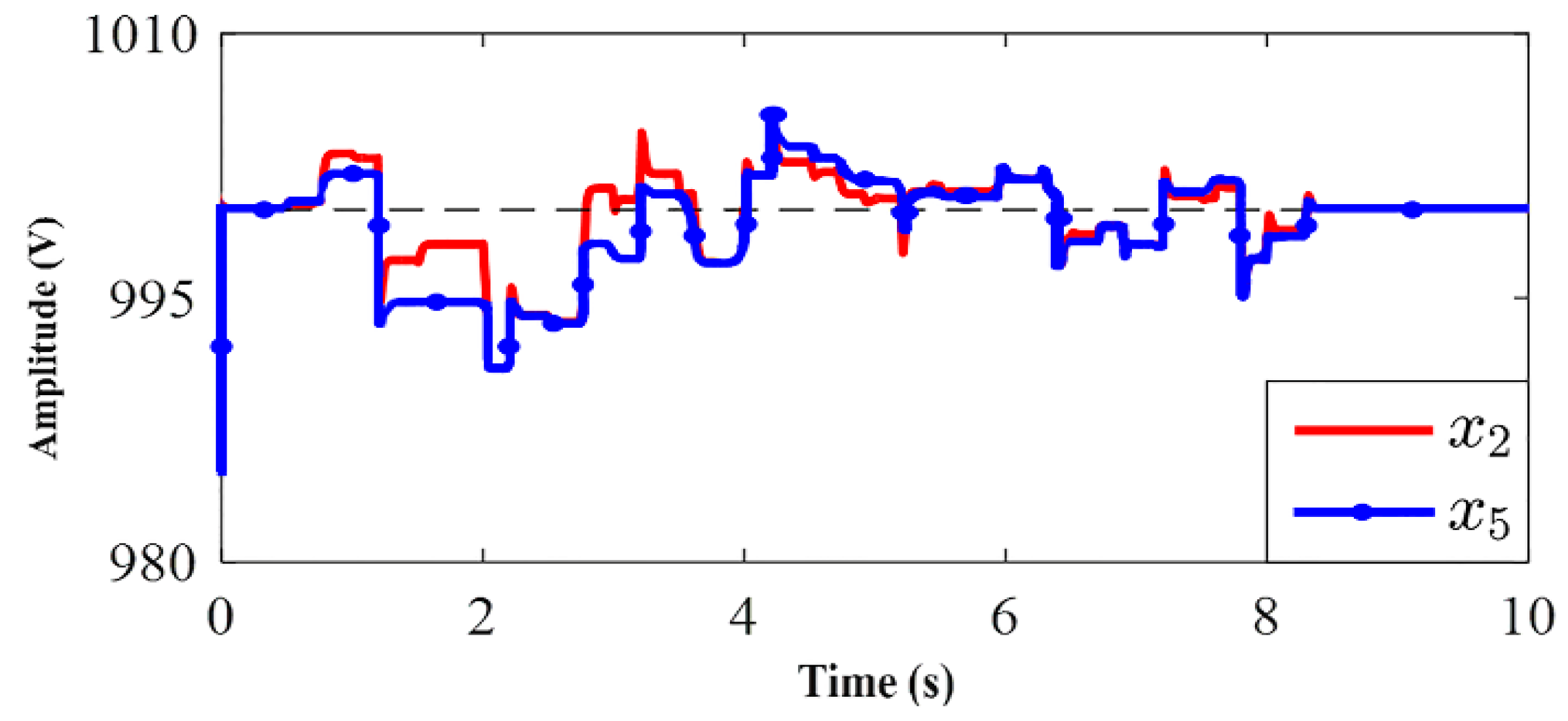
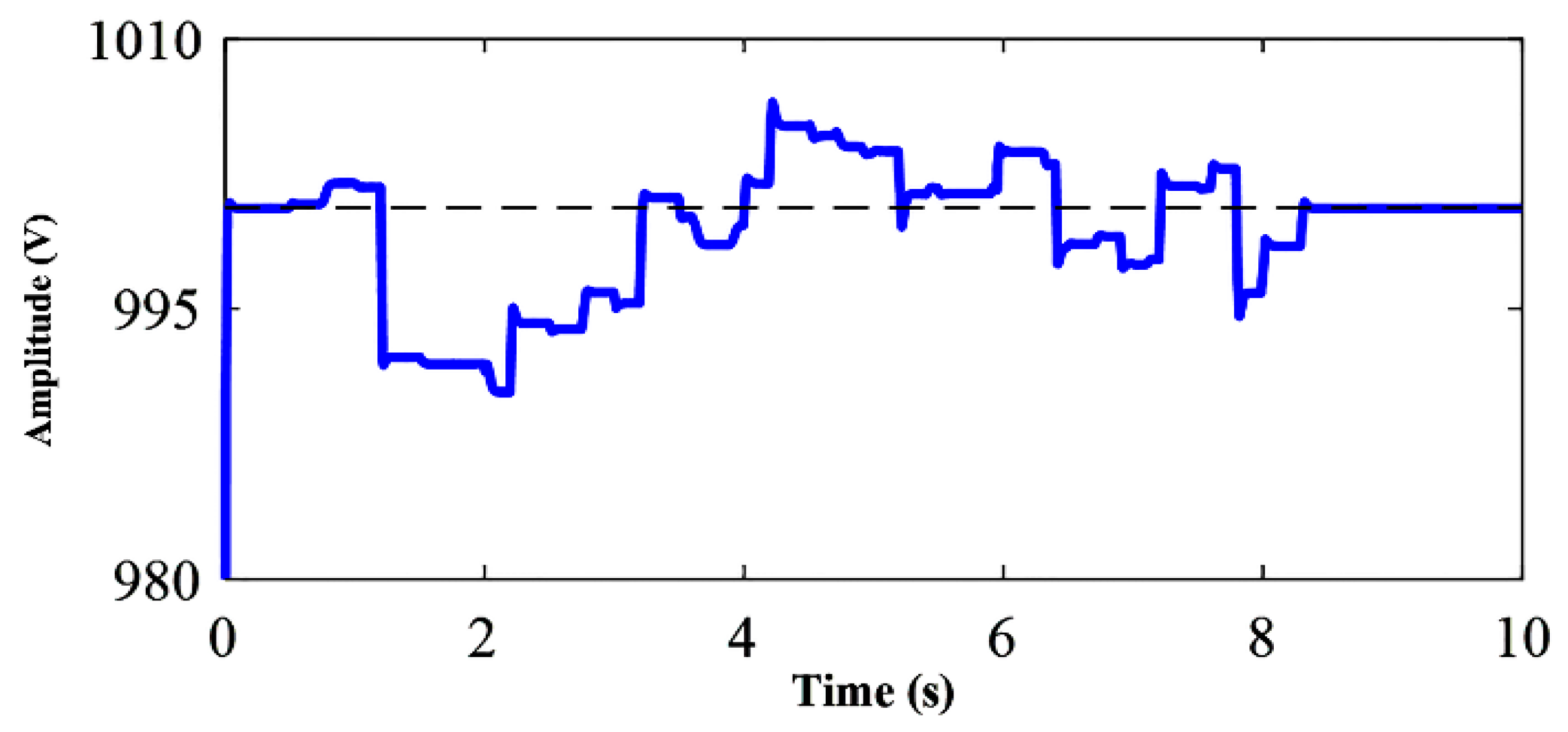
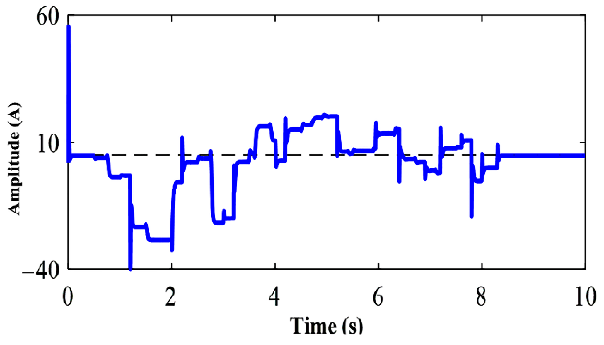
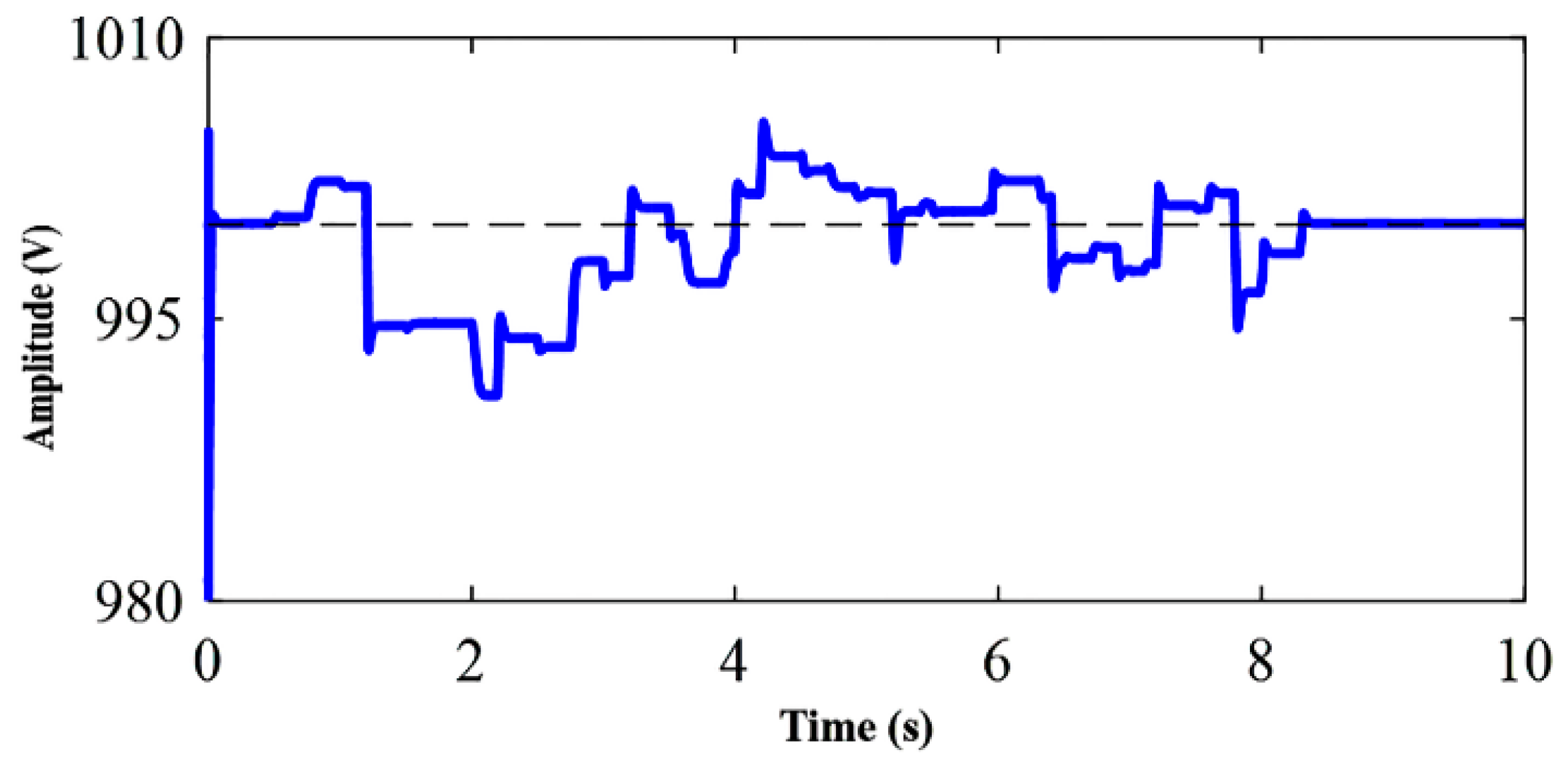
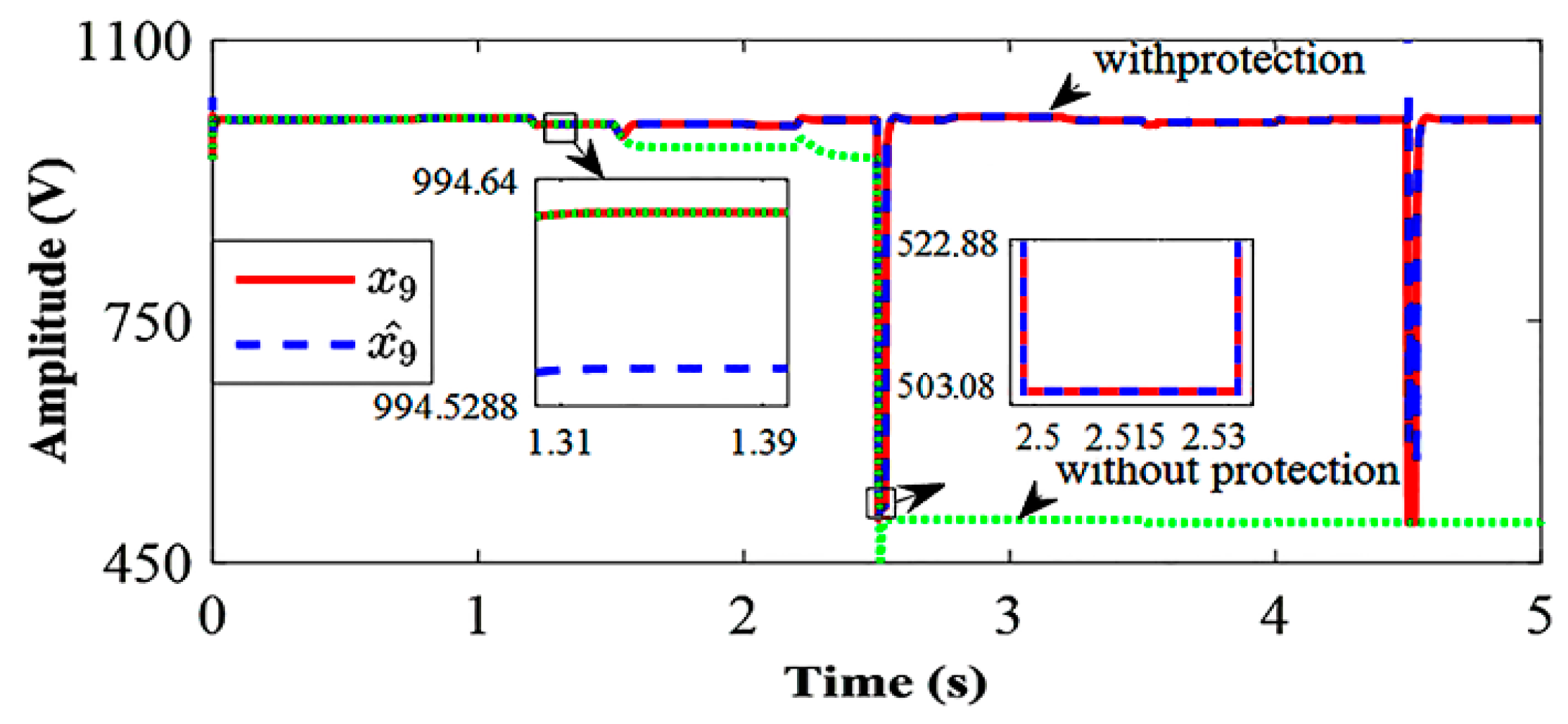
Because of the rapid increase in the fault current in a dc microgrid, it is necessary to detect faults at the right time and isolate the faulted segment. The first part of the results is related to the voltage control of the dc bus via the SDRE controller and the second part is dedicated to the SDRE observer results for fast fault detection. In both parts, it is necessary to first consider a state-dependent coefficient (SDC) representation of the Equation (1). The coefficients of the state equation were extracted as follows. The SDRE controller objectives for the studied network are the setting of the output voltages of the PV system, the battery, the capacitor bank and the dc bus, which can be used for control purposes using u 1 ( t ) , u 2 ( t ) and u 3 ( t ) inputs. For this purpose, the optimal equilibrium point of the system is obtained with zero placement of the right side of Equation (1). The desired equilibrium point is obtained using the parameters of Table 1 as follows:
x 1 = 300   , x 2 = 1000 ,   x 3 = 0 ,   x 4 = 400 ,   x 5 = 1000 ,
x 6   = 0 ,   x 7 = 1000 ,   x 8 = 5 ,     x 9 = 1000 ,
u 1 = 0.7 ,   u 2 = 0.6 , u 3 = 0.5
In order to transfer this equilibrium to the space state, the following variables are used:
Δ x 1 = x 1 300   ,   Δ x 2 = x 2 1000 ,   Δ x 3 = x 3
Δ x 4 = x 4 400 ,   Δ x 5 = x 5 1000 ,   Δ x 6   = x 6
Δ x 7 = x 7 1000 , Δ x 8 = x 8 5 ,   Δ x 9 = x 9 1000
Δ u 1 = u 1 0.7 ,   Δ u 2 = u 2 0.6 ,   Δ u 3 = u 3 0.5
By changing the given variables, Equation (1) can be rewritten as follows:
Δ x ˙ 1 = 1 R 1 C 1 Δ x 1 1 C 1 Δ x 3 Δ x ˙ 2 = 1 R 2 C 2 Δ x 2 + 0.3 C 2 Δ x 3 + 1 R 2 C 2 Δ x 9 1 R 2 C 2 Δ x 3 Δ u 1 Δ x ˙ 3 = 1 L 3 Δ x 1 1 L 3 ( 0.3 Δ x 2 R 01 Δ x 3 ) + Δ x 2 L 3 Δ u 1 Δ x ˙ 4 = 1 R 4 C 4 Δ x 4 1 C 4 Δ x 6 Δ x ˙ 5 = 1 R 5 C 5 Δ x 5 0.004 R 5 C 5 Δ x 6 1 R 5 C 5 Δ x 9 Δ x 6 C 5 Δ u 2 Δ x ˙ 6 = 1 L 6 ( Δ x 4 0.4 Δ x 5 R 04 Δ x 6 ) + Δ x 5 L 6 Δ u 2 Δ x ˙ 7 = 1 R 7 C 7 Δ x 7 1 C 7 Δ x 8 + 1 R 7 C 7 Δ x 9 Δ x ˙ 8 = 1 L 8 ( Δ x 7 R 08 Δ x 8 ) +   1900 L 8 Δ u 3 Δ x ˙ 9 = 1 C 9 ( Δ x 2 Δ x 9 R 2 + Δ x 5 Δ x 9 R 5 + Δ x 7 Δ x 9 R 7 Δ x 9 R L )
A = [ 1 R 1 C 1 0 1 C 1 0 0 0 0 0 0 0 1 R 2 C 2 0.3 R 2 C 2 0 0 0 0 0 1 R 2 C 2 1 L 3 0.3 L 3 0.01 L 6 0 0 0 0 0 0 0 0 0 1 R 4 C 4 0 1 C 4 0 0 0 0 0 0 0 1 R 5 C 5 0.004 R 5 C 5 0 0 1 R 5 C 5 0 0 0 1 L 6 0.4 L 6 0.01 L 6 0 0 0 0 0 0 0 0 0 1 R 7 C 7 1 C 7 1 R 7 C 7 0 0 0 0 0 0 1 L 8 R 08 L 8 0 0 1 C 9 R 2 0 0 1 C 9 R 5 0 1 C 9 R 7 0 ( 1 R 2 1 R 5 1 R 7 1 R L ) ] B ( x ( t ) ) = [ 0 Δ x 3 C 2 Δ x 2 L 3 0 0 0 0 0 0 0 0 0 0 Δ x 6 C 5 Δ x 5 L 6 0 0 0 0 0 0 0 0 0 0 1900 L 8 0 ] T
In the following simulations, x ˙ ( t ) = A x ( t ) + B ( x ( t ) ) u ( t ) is used, and the matrices A and B are given below, and x ( t ) is the state vector of the system and u ( t ) = [ u 1 ( t ) u 2 ( t ) u 3 ( t ) ] T is the input of the system control. It is necessary to check the point-to-point controllability of pair ( A , B ( x ( t ) ) ) . Therefore, there is a possibility of designing an SDRE controller for the current study. In the following, the weight matrices in the simulations are selected as follows:
Q = 10   I 9 , R = 10 6 diag ( 0.009 , 7 , 2 )
In the simulations, it is assumed that the proposed network is exposed to various disturbances, including the voltage of the PV system Vpv, the battery voltage VB, the capacitance bank voltage VS, and the load variations. It should be noted that in the following, it is assumed that these disturbances are independently altered, and their curves are given in Figure 3 and Figure 4.
The simulation results in the presence of SDRE controller are shown in Figure 5. As can be seen, despite the large variations in C1 and C4 voltage, the SDRE controller was able to maintain the stability of the system after disturbances.
Figure 6 demonstrates simultaneous disturbances of VPV and VB in the presence of the SDRE controller. As can be seen, the voltage and current of the PV system and the battery were controlled within a few seconds and restored to their equilibrium state.
Figure 7 and Figure 8 show the capacitor-banks voltage and current variations during power generation and load changes. As can be seen, in spite of significant disturbances, the proposed controller has returned the voltage and current to equilibrium points within a few seconds and maintained the stability of the system.
Figure 9 shows the dc bus voltage, which, in spite of the disturbances in the system, the SDRE controller was able to regulate properly the voltage and system stability was ensured. As can be seen, the control input range is small in spite of the high variations in the PV panel system output voltage, the battery, and the capacitor bank, as well as the load variation. The results of the simulations indicate the capability of the proposed method for the islanded dc microgrids and exposed to disturbances. In this work, the criterion of return to the initial equilibrium point after the end of the disturbance is proposed as a dc microgrid stability index. As can be seen in Figure 5, Figure 6, Figure 7, Figure 8 and Figure 9, voltage and current values return back to their respective equilibrium values prior to the disturbance occurrence.

4.2. SDRE Observer

In the following, the performance of fault detection based on the SDRE observer is investigated. Weight matrixes W and V are considered as follows:
V = 10 4   I 9 ,     W = 10 6   diag ( 1 , 50 , 1 , 1 , 50 , 1 , 50 , 1 , 50 )
In the simulations of this section, it is assumed that a fault occurs at 1.5 s in the C1 capacitor and another fault in 3.5 s in the C4 capacitor. As shown in Figure 10, at this time, the C1 voltage decreased from 300 V to 10 V, and the voltage of the C4 capacitor decreased from 400 to 10 V, and correspondingly, in Figure 11, the output current of the PV system and the battery decreased. According to Figure 10, the fault detection time for the proposed SDRE method is 30 ms. Meanwhile, the fault detection system compares the actual system output with the output of the SDRE observer and formed a non-zero residual current, as shown in Figure 12, which, with the definition of the appropriate threshold—here the threshold is assumed 50 mA—makes it possible to detect the fault. As mentioned, among the most important issues in the field of fault detection is to not identify disturbances as faults. As shown in the previous section, despite the above-mentioned disturbances, Figure 11 shows that the fault occurrence system did not trip any of these times.
In order to show the proposed fault detection scheme’s ability and its non-dependence on the fault location, a fault occurred at 2.5 s on the output of the C7 capacitor, and another in 4.5 s had occurred on the load bus. As shown in Figure 13 and Figure 14, at a moment of 2.5 s, the capacitor voltage C7 decreased from 1000 to 500 V and the load bus voltage reduced from 1000 to 500 V. In this case, as shown in Figure 15, the capacitor-bank output current has increased. As it can be seen from Figure 16, the fault detection time for the proposed SDRE method is 30 ms. It is apparent in Figure 16, that the threshold was considered 50 mA which was feasible for fault detection.
As noted, one of the most important problems in the field of microgrid protection is the detection of disturbance as a fault occurrence. As a result, the proper selection of threshold value has a significant effect on this goal. In order to investigate this issue, in the studied dc microgrid, it is assumed that the dc resistive load unexpectedly has suddenly disconnected at 0.2 ms and reconnected again. It is also assumed that the fault has occurred in the C1 capacitor within 0.4 ms. As can be seen from Figure 17, by selecting a threshold value of 50, the fault occurrence warning is not activated at this time.
In fact, for the sake of generalization, we can say that the threshold value for the fault detection occurrence is chosen to be greater than the disturbances range. As can be seen, the maximum non-zero residual current of C1 is less than 3 mA in the disturbance condition, whereas the non-zero residual current of the C1 is about 700 mA when the fault occurs. As a result, in order to provide the margin of assurance of the performance of the protection system, the threshold value of the fault occurrence is considered as 50 mA, so that both the fault occurrence is quickly detected and the disturbance is not considered as a fault.

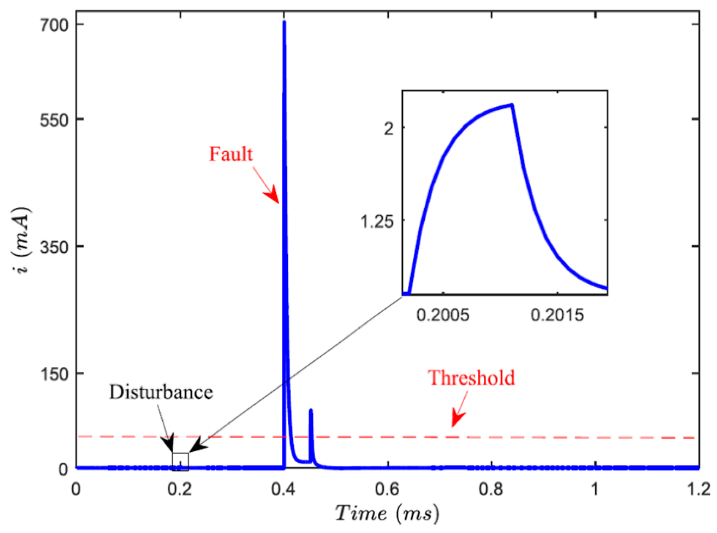
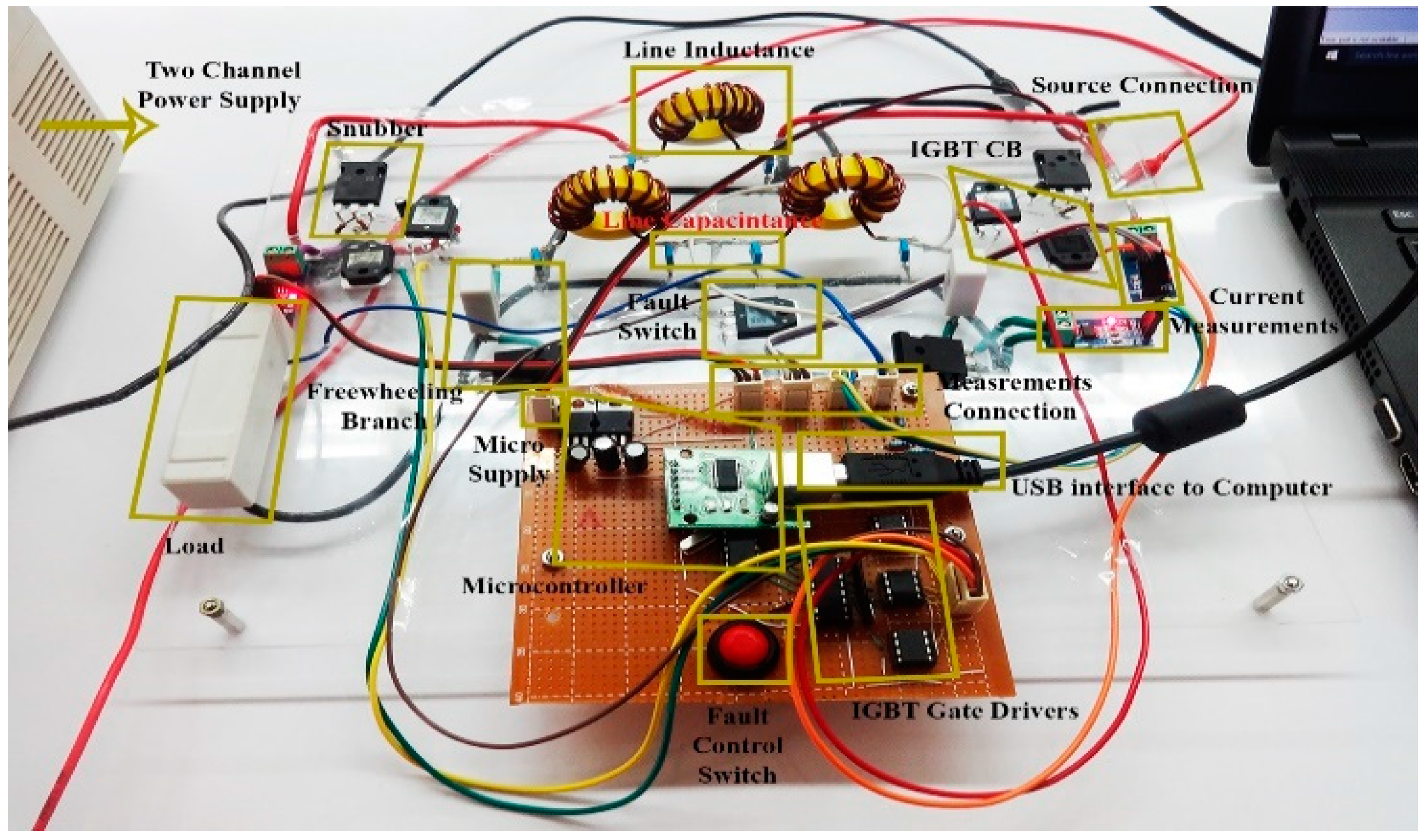
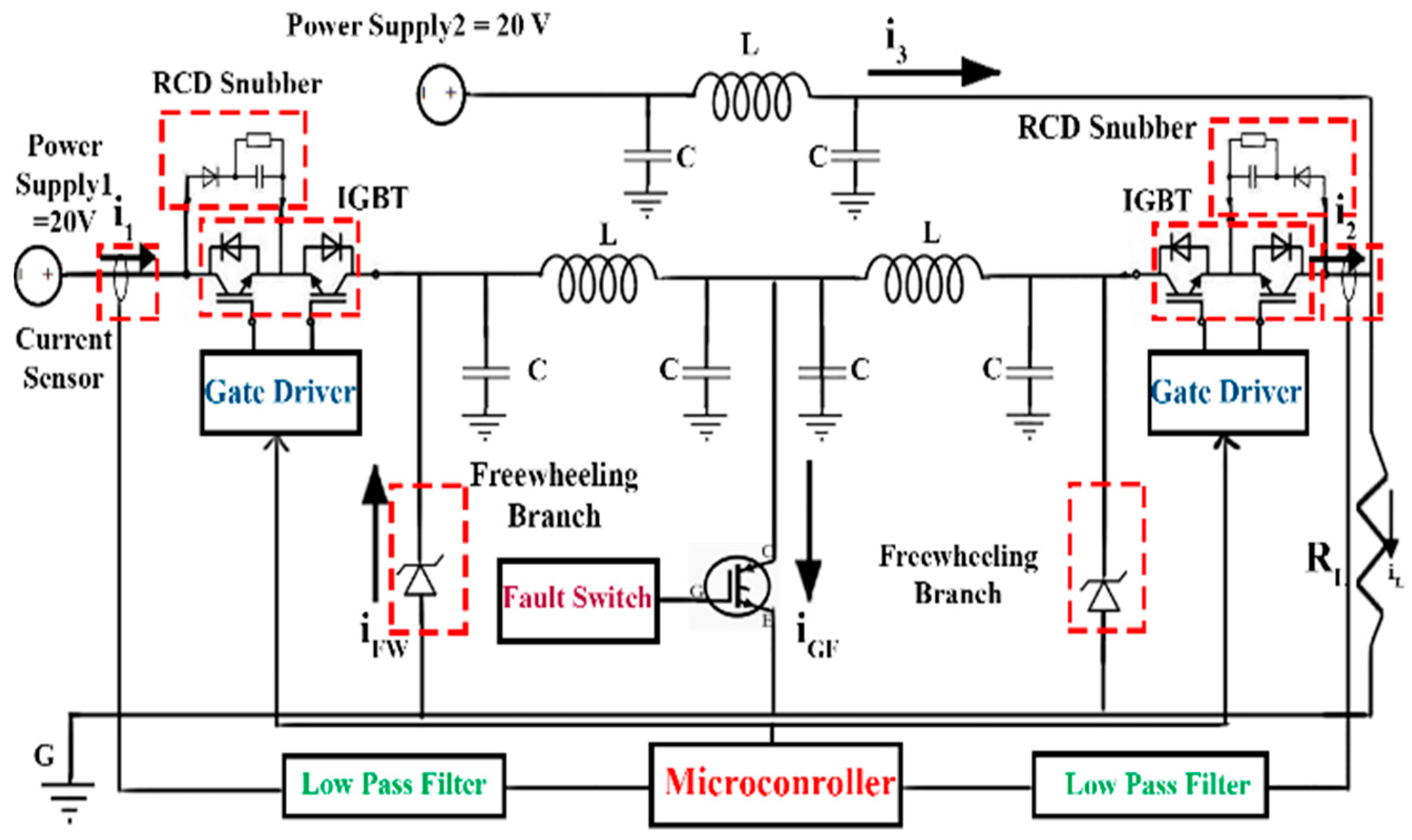
5. Experimental Verification

The simulated dc microgrid and proposed fault detection algorithm were implemented and tested in an experimental prototype in order to validate the feasibility of the proposed protection approach. A laboratory-scale experimental setup in 20:1 scale from the simulation circuit was built to verify the conceivability of the proposed SDRE observer method using actual hardware. Due to overwhelming and consecutive disturbances, as well as practical limitations, implementation of the SDRE controller in this section has been neglected and the performance of SDRE observer scheme is analyzed. In the simulations, four disturbances, including severe variations in the output voltages of the PV system, BESS, and the capacitor bank, as well as load variations are considered as disturbances.
In the lab test setup, the PV system, the BESS, and the capacitor bank are modeled and implemented by means of the power supply system as MASTECH HY3005-2 two-channel, 30-V 3-A power supply and MASTECH HY3005-1 one-channel, 30-V 3-A power supply. Inside these sources, there is a protective element that causes the power supply to be tripped if there are overwhelming and consecutive variations in the power supply currents. As a result, it is not possible to produce large disturbances in the power supply outputs.
Further, a 10 Ω-30 W wire-wound resistor has been used to implement the dc load. In order to apply load variations, it is necessary to use variable wire-wound resistance, which was not accessible for us. The prototype test-bed including a dc source, dc load, and insulated-gate bipolar transistor (IGBT) solid-state circuit breaker, but only with a positive line to simulate a line-to-ground (LG) fault. The employed equipment, the characteristics and their corresponding descriptions are given in Table 2. It should be noted that, apart from the implementation of the fault detection based on the SDRE observer method, the differential fault detection method proposed in [15] is also implemented to provide a comparison of the fault detection times between the two schemes. In addition, in the implementation, dc-dc converters modeling is ignored and the BESS and bank capacitor are modeled as a simple ideal source.
The amount of threshold for the differential fault detection was assumed as 20% of the quantity of the simulation in [15]. In this test, the measured current analog–digital (A/D) transformation is fulfilled in a 50-µs interval. The use of a microcontroller, IGBTs gate drivers and a schematic diagram of the prototype experimental test bed implementation are shown in Figure 18 and Figure 19. The red light of light emitting diodes (LEDs) of current measurement modules indicate the link between the current sensor and the microcontroller.
An LG fault was practically examined and applied at 1s. The power supply feeds 20W (20 V, 1 A) to the load in the steady-state utilization. It is remarkable that the power supply could supply a near 20 A-peak transient fault current for 100 ms until every channel attains a 3 A rated current amount.
Figure 20 shows the residual current comparison of C1 capacitors during the fault occurrence without protection, with differential protection, and with SDRE observer protection. It is apparent, the transient three A fault current passes through the circuit without protection. While, by investigation of the SDRE-observer and the differential method figures, it can be deduced that the proposed SDRE observer protection detects the fault incidence more quickly. Obviously, the current value attains zero after the trip of IGBTs.
Figure 21 shows the voltage of dc demand and the freewheeling current without protection, with differential, and SDRE observer protection modes. It is apparent that the fault detection time for the proposed SDRE method in experimental implementation is 96 ms and for the differential method proposed in [15], it is 114 ms. Additionally, load voltage when using the SDRE observer protection is restored faster and has a smaller transient-current. The load voltage attains a small value without protection. Due to the fast fault detection and consequent prevention of huge rises in the fault current, the SDRE observer protection leads to a lower current in the freewheeling path rather than the differential protection method, i.e., reduced protective system expenses and the conceivability of utilizing the simpler, smaller diodes. Figure 22 demonstrates the voltage of IGBT breakers with snubber attendance in differential and SDRE observer modes. Exploiting the SDRE observer protection led to a reduction in the pick of voltage on the IGBT breakers, which permitted the utilization of breakers with lower nominal insulation voltages. In addition, by taking advantage of the SDRE observer controller, IGBTs tolerated lower transient voltages that caused a reduction in the possibility of IGBT breaker failure.
The implementation results of the SDRE observer protection algorithm prove the usefulness of this study in terms of practical applications. The proposed schemes are applicable and more feasible, efficient, fast, and accurate than those of the differential algorithm. Consequently, the proposed approach can also be implemented in real-scale different dc islanded configurations.

6. Discussion

The protection system used in this paper is a master–slave database type. Therefore, it requires high-speed communication and synchronization [13,14,15]. Every parameter is constantly tracked and measured by slave controllers. The measured values are sent to the master controller, which is the main processor of the protection system. So, first, the master controller processes the data, and, if a fault occurs, the slave controller will isolate the faulted segment by means of the IGBTs. By comparison of the simulation and experiment, it can be concluded that there is a reasonable difference between fault detection time in the simulation and experimental implementation. Fault detection time based on the proposed SDRE in the simulation section is 30 ms and 96 ms for experimental implementation based on the proposed SDRE method. Almost 66 ms difference in fault detection between the simulation and experimental implementation is noted due to the ACS 712-30 and ADS1115 sampling frequency and computation time in the microcontroller.
In this work, the PV module can have a level of uncertainty. The proposed model is based on state variables and the uncertainty in PV will lead to changes in the state variables, such as Δx2 and Δx3 which is considered in the proposed method (Equation (9)). As a result, with the occurrence of uncertainty, the values of the state variables (Δx2 and Δx3) will be changed and updated, and as a result, the proposed SDRE method can have the appropriate control and protection performance in this state. So, one of the merits of the proposed method is robustness against uncertainty.

7. Conclusions

In this paper, an integrated control and protection system based on an SDRE controller-observer, applied to islanded dc microgrids is presented. The proposed protection approach is conceived so that the actual output of the system, with its rated output, calculated by a nonlinear observer, is compared, and if there is a difference in these two non-zero residual currents then this can lead to fault detection in the quickest time possible. The proposed method is fast and cost-effective. Simulation and experimental results have shown that the proposed method was able to detect a fault and maintain the performance of dc microgrids against external disturbances in an acceptable manner. An SDRE controller was used to control the output voltage of the microgrid. Thanks to the implementation of the SDRE observer protection algorithm, these schemes are applicable and becoming more feasible, efficient, fast, and accurate compared to those of the differential algorithm. The proposed approach can be also implemented in different dc islanded configurations.

Author Contributions

Conceptualization, A.A.; methodology, A.A.; software. A.A.; validation, A.A. and J.M.G.; formal analysis, A.A.; investigation, K.M. and J.M.G.; data curation, A.A.; writing—original draft preparation, A.A.; writing—review and editing, K.M. and J.M.G.; supervision, K.M. and J.M.G.; funding acquisition, J.M.G. All authors have read and agreed to the published version of the manuscript.

Funding

The works were completed by A. Abdali and K. Mazlumi is supported by the University of Zanjan, Zanjan, Iran. The work was completed by J. M. Guerrero is supported by VILLUM FONDEN under the VILLUM Investigator Grant (No. 25920): Center for Research on Microgrids (CROM); www.crom.et.aau.dk.

Conflicts of Interest

The authors declare no conflict of interest.

References

  1. Li, Z.; Zheng, T.; Wang, Y.; Yang, C. A Hierarchical Coordinative Control Strategy for Solid State Transformer Based DC Microgrids. Appl. Sci. 2020, 10, 6853. [Google Scholar] [CrossRef]
  2. Saponara, S.; Saletti, R.; Mihet-Popa, L. Recent Trends in DC and Hybrid Microgrids: Opportunities from Renewables Sources, Battery Energy Storages and Bi-Directional Converters. Appl. Sci. 2020, 10, 4388. [Google Scholar] [CrossRef]
  3. Adi, F.S.; Lee, Y.J.; Song, H. State Estimation for DC Microgrids using Modified Long Short-Term Memory Networks. Appl. Sci. 2020, 10, 3028. [Google Scholar] [CrossRef]
  4. Yin, C.; Wu, H.; Sechilariu, M.; Locment, F. Power management strategy for an autonomous DC microgrid. Appl. Sci. 2018, 8, 2202. [Google Scholar] [CrossRef] [Green Version]
  5. Abdali, A.; Mazlumi, K.; Noroozian, R. Novel Method of Low and High Impedance Fault Detection in LVDC Microgrids. In Proceedings of the 11th International Conference on Protection and Automation of Power System, Tehran, Iran, 18–19 January 2017. [Google Scholar]
  6. Yaqobi, M.A.; Matayoshi, H.; Danish, M.S.S.; Lotfy, M.E.; Howlader, A.M.; Tomonobu, S. Low-Voltage Solid-State DC Breaker for Fault Protection Applications in Isolated DC Microgrid Cluster. Appl. Sci. 2019, 9, 723. [Google Scholar] [CrossRef] [Green Version]
  7. Salomonsson, D.; Soder, L.; Sannino, A. Protection of low-voltage DC microgrids. IEEE Trans. Power Deliv. 2009, 24, 1045–1053. [Google Scholar] [CrossRef]
  8. Abdali, A.; Mazlumi, K.; Noroozian, R. Fast fault detection and isolation in low-voltage DC microgrids using fuzzy inference system. In Proceedings of the 5th Iranian Joint Congress on Fuzzy and Intelligent Systems (CFIS), Qazvin, Iran, 7–9 March 2017; pp. 172–177. [Google Scholar]
  9. Lv, C.; Zheng, X.; Tai, N.; Chen, S. Single-ended protection scheme for VSC-based DC microgrid lines. Energies 2018, 11, 1440. [Google Scholar] [CrossRef] [Green Version]
  10. Abdali, A.; Mazlumi, K.; Noroozian, R. A precise fault location scheme for low-voltage dc microgrids systems using multi-layer perceptron neural network. Sigma J. Eng. Nat. Sci. 2018, 36, 821–834. [Google Scholar]
  11. Abdali, A.; Noroozian, R.; Mazlumi, K. Simultaneous control and protection schemes for DC multi microgrids systems. Int. J. Electr. Power Energy Syst. 2019, 104, 230–245. [Google Scholar] [CrossRef]
  12. Abdali, A.; Mazlumi, K.; Noroozian, R. High-speed fault detection and location in DC microgrids systems using Multi-Criterion System and neural network. Appl. Soft Comput. 2019, 79, 341–353. [Google Scholar] [CrossRef]
  13. Farhadi, M.; Mohammed, O.A. Event-based protection scheme for a multiterminal hybrid DC power system. IEEE Trans. Smart Grid 2015, 6, 1658–1669. [Google Scholar] [CrossRef]
  14. Fletcher, S.D.; Norman, P.J.; Fong, K.; Galloway, S.J.; Burt, G.M. High-speed differential protection for smart DC distribution systems. IEEE Trans. Smart Grid 2014, 5, 2610–2617. [Google Scholar] [CrossRef] [Green Version]
  15. Park, J.D.; Candelaria, J. Fault detection and isolation in low-voltage DC-bus microgrid system. IEEE Trans. Power Deliv. 2013, 28, 779–787. [Google Scholar] [CrossRef]
  16. Esreraig, M.; Mitra, J. An observer-based protection system for microgrids. In Proceedings of the 2011 IEEE Power and Energy Society General Meeting, Detroit, MI, USA, 24–28 July 2011; pp. 1–7. [Google Scholar]
  17. Esreraig, M.; Mitra, J. Microgrid protection using system observer and minimum measurement set. Int. Trans. Electr. Energy Syst. 2015, 25, 607–622. [Google Scholar] [CrossRef]
  18. Hwas, A.; Katebi, R. Nonlinear observer-based fault detection and isolation for wind turbines. In Proceedings of the 22nd Mediterranean Conference on Control and Automation, Palermo, Italy, 16–19 June 2014; pp. 870–875. [Google Scholar]
  19. Xu, L.; Chen, D. Control and operation of a DC microgrid with variable generation and energy storage. IEEE Trans. Power Deliv. 2011, 26, 2513–2522. [Google Scholar] [CrossRef]
  20. Çimen, T. Systematic and effective design of nonlinear feedback controllers via the state-dependent Riccati equation (SDRE) method. Annu. Rev. Control 2010, 34, 32–51. [Google Scholar] [CrossRef]
  21. Chen, W.; Saif, M. An iterative learning observer for fault detection and accommodation in nonlinear time-delay systems. Int. J. Robust Nonlinear Control IFAC Affil. J. 2006, 16, 1–19. [Google Scholar] [CrossRef]
Figure 1. Schematic structure of photovoltaics (PV)-battery islanded dc microgrids.
Applsci 10 08847 g001
Figure 2. Studied PV-battery islanded dc microgrid configuration.
Applsci 10 08847 g002
Figure 3. Capacitor bank voltage variations super capacitor voltage (VS).
Applsci 10 08847 g003
Figure 4. PV voltage (Vpv) battery storage voltage (VB) and load variation.
Applsci 10 08847 g004
Figure 5. Voltage of C1 and C4 Capacitors in the presence of state-dependent Riccati equation (SDRE) controller.
Applsci 10 08847 g005
Figure 6. PV panel array and battery voltage in the presence of SDRE controller.
Applsci 10 08847 g006
Figure 7. Capacitor bank voltage in the presence of SDRE controller.
Applsci 10 08847 g007
Figure 8. Output current of the capacitor bank in the presence of SDRE controller.
Applsci 10 08847 g008
Figure 9. Dc bus voltage in the presence of SDRE controller.
Applsci 10 08847 g009
Figure 10. Capacitance C1 and C4 voltage during fault occurrence.
Applsci 10 08847 g010
Figure 11. Inductance L3 and L6 voltages during fault occurrence.
Applsci 10 08847 g011
Figure 12. Residual currents of C1 and C4 capacitors during fault occurrence.
Applsci 10 08847 g012
Figure 13. Capacitor voltage during fault occurrence in capacitor C7.
Applsci 10 08847 g013
Figure 14. Capacitor output current during fault occurrence.
Applsci 10 08847 g014
Figure 15. Load bus voltage of C9 capacitor during fault occurrence.
Applsci 10 08847 g015
Figure 16. Residual current of C7 and C9 capacitors during fault occurrence.
Applsci 10 08847 g016
Figure 17. Non-zero residual current of the C1 for disturbance and fault occurrence.
Applsci 10 08847 g017
Figure 18. Experimental testbed, microcontroller board, and IGBTs gate drivers.
Applsci 10 08847 g018
Figure 19. Electrical scheme of the testbed experimental prototype.
Applsci 10 08847 g019
Figure 20. Residual current of C1 capacitor during the fault occurrence.
Applsci 10 08847 g020
Figure 21. Voltage of resistive load and the current of freewheeling in no protection, differential, and SDRE observer modes.
Applsci 10 08847 g021
Figure 22. Voltage of IGBT breakers with snubber attendance in differential, and SDRE observer modes.
Applsci 10 08847 g022
Table 1. Studied direct current (dc) Microgrid Parameters.
ParametersValueParametersValueParametersValue
0.033   H L 3 0.1   Ω   R 7 0.1   F C 1
0.033   H L 6 0.01   Ω R 01 0.01   F C 2
0.0033   H L 8 0.01   Ω R 02 0.1   F C 4
0.1   Ω R 2 0.01   Ω R 04 0.01   F C 5
0.1   Ω R 4 0.01   Ω R 05 0.01   F C 7
0.01   Ω R 5 0.01   Ω R 07 0.0001 F C 9
1000   V V b u s 0.01   Ω R 08 0.1   Ω R 1
Table 2. Equipment Description.
EquipmentDescription
MASTECH HY3005-2, 30-V 3-A power supply, 2 channelsUtilized for 20 V VPV and VB
MASTECH HY3005-2, 30-V 3-A power supply, 2 channelsUtilized for 20 V VS
10 Ω, 30-Watt resistorUtilized for resistive dc load
Three 15 μH inductorUtilized for the inductance of VPV, VB and Vs
Six 220 pF capacitorUtilized for capacitance of VPV, VB and Vs
Two STGW38IH130D IGBT modulesUtilized to for circuit breaker
One IKW40N120H3 IGBT Utilized to employ the line to ground (LG) fault
FEP30GP Diode, 2 Ω resistorUtilized for freewheeling branches
FEP30GP Diode, 10 μF capacitor, 12 Ω resistorUtilized for Resistance Capacitance Diode (RCD) snubber
ATMEGA8L-8PU MicrocontrollerImplemented for the protective system
Three ACS 712-30 and ADS1115 modulesUtilized for sampling current, 3rd low-pass filter, A/D
Three TC427CPA microchips, ULN2003 APC bufferUtilized for insulated-gate bipolar transistors (IGBTs) gate drivers
Two HCPL-7840 optocouplerUtilized for differentiation of analog and digital grounds, noise decrement, isolation
Publisher’s Note: MDPI stays neutral with regard to jurisdictional claims in published maps and institutional affiliations.

