Precast Bridges of Bamboo Reinforced Concrete in Disadvantaged Village Areas in Indonesia


Faculty of Engineering, University of Muhammadiyah Jember, Jember 68121, Indonesia
Appl. Sci. 2020, 10(20), 7158; https://doi.org/10.3390/app10207158
Submission received: 29 August 2020
/
Revised: 6 October 2020
/
Accepted: 10 October 2020
/
Published: 14 October 2020
(This article belongs to the Collection Advanced Technologies in Wood Science)
Abstract
:Bamboo is an inexpensive, environmentally friendly, and renewable building material that thrives in Indonesia. Bamboo has a high tensile strength but also has weaknesses, namely, it is easily attacked by insects and has high water absorption. Utilization of bamboo as a precast concrete bridge reinforcement must be treated first through soaking, drying, and giving a waterproof coating and sand. This research aimed to obtain a precast bamboo reinforced concrete bridge technology with good integrity, with measuring parameters of deformation and deflection according to AASHTO standards. The dimensions of the bridge were a span of 320 cm, a width of 224 cm, and a height of 115 cm. Two bridge frames were connected by four bridge beams. The bridge plate was made of a 10-cm-thick concrete plate. The bridge support of the reinforced concrete is assumed to be the hinge support and the rubber bearing is assumed to be the roller support. The bamboo reinforced concrete frame bridge test was carried out directly with a load of a minibus-type vehicle. The test results show that the precast bamboo reinforced concrete frame bridges have sufficiently good integrity; that is, they can distribute loads with deflection and deformation that do not exceed their permits. The maximum displacement occurs in the bridge frame of 0.25 mm, meeting the requirements based on the AASTHO and RSNI T-12-2004 standards, which is not more than Δmax = L/800 = 3.75 mm. The maximum deformation occurs in the bridge beam of 0.20 mm, and the bridge frame of 0.13 mm meets the requirements based on the AASTHO and RSNI T-12-2004 standards, which is not more than δmax = L/800 = 3.75 mm.
1. Introduction
The continued use of industrial products has caused permanent pollution. Permanent pollution is environmental pollution caused by industrial waste without recycling or the continuous use of raw materials from nature without renewal. The use of bamboo as a renewable building material can reduce pollution and maintain a healthy environment [1]. Bamboo is a grass plant with cavities and nodes in its stems [2]. Bamboo is a renewable building material, such as wood. Bamboo has the advantage of being economical, growing fast, and does not take long to achieve mechanical resistance. Mechanical resistance of bamboo, such as tensile strength, flexural strength, and other mechanical properties, can be achieved in a relatively fast time, namely at the age of bamboo ranging from 3–4 years [3]. Bamboo is also very abundant in tropical and subtropical areas around the world [1]. Indonesia is a country with a tropical climate. One of the plants that can thrive in Indonesia is bamboo. Bamboo is scattered throughout Indonesia. Bamboo has been widely used as a material for simple structures, such as warehouses, bridges, and village traditional houses, and for handicrafts for rural communities. In Indonesia, there are more than 100 species of bamboo. Around the world, there are ±1500 species of bamboo [4]. In terms of its potential, in 2000 the total area of bamboo plants in Indonesia was 2,104,000 ha, consisting of 690,000 ha of bamboo planted in forest areas and 1,414,000 ha of bamboo plant areas outside forest areas [5]. Arsad (2015) [5] revealed that in the Hulu Sungai Selatan Regency, the bamboo area was estimated to be around 22,158 ha, with a production of about 3000 stems/ha. The description of the potential for bamboo production in East Java is 29,950,000 stems/year, Yogyakarta 2,900,000 stems/year, Central Java 24,730,000 stems/year, and West Java 14,130,000 stems/year [6]. With such a large production potential, efforts must be made to increase its economic value, including being used as an alternative to concrete reinforcement. The best bamboos that are widely used as structural elements are the petung bamboo (Dendrocalamus asper) and ori bamboo (Bambusa blumeana), because these two bamboos have the best technical specifications with a high tensile strength. The use of bamboo as concrete reinforcement for simple construction is applied specifically in underdeveloped village areas that have a lot of bamboo.
Bamboo for concrete reinforcement is because it has a relatively high tensile strength. The tensile strength of bamboo can reach 370 MPa in its outer fibers [1]. The failure of the elements of the bridge frame or roof truss usually occurs in the tensile stem elements. Bamboo has a high enough tensile strength suitable for use in tensile elements. Bamboo is suitable for use in tensile elements, simple construction, such as roof trusses, simple bridge trusses, simple house construction elements, and so on. Muhtar et al. (2018) [7] tested the pull-out of bamboo reinforcement with a layer of Sikadur®-752 and hose clamps embedded in a concrete cylinder, showing an increase in tensile stress of up to 240% compared to untreated bamboo reinforced concrete (BRC). A single BRC beam with a bamboo reinforcing area ratio of 4% exceeds the ultimate load of a steel-reinforced concrete (SRC) beam by 38.54% with a steel reinforcement area ratio of 0.89% [8]. However, bamboo also has weaknesses, which are being easily attacked by insects and having high water absorption. This study did not test for fungal and insect attacks, but the technology to prevent fungus and insect attack was based on the opinion and research of Ridley (1911) [2] and Stebbings (1904) [9], namely that soaking in water for two months is sufficient to prevent insect attack. Soaking and drying aim to remove the starch or sugar content in bamboo. The criterion for sufficient soaking is that the bamboo smells bad. The soaking causes the bamboo’s water content to increase and decrease its strength; however, after drying it undergoes a transition from a brittle behavior to a very resilient behavior [10]. The effect of alkaline cement does not cause the bamboo to decrease in strength. According to Ming Li (2017) [11], the content of bamboo fiber (BF) treated with the right alkaline can effectively increase toughness, flexural strength, and tensile strength. Moe Thwe (2003) [12] conducted a study on the durability of bamboo with treatment using calcium hydroxide (CaOH2) to increase flexibility and durability.
In this study, the technology used to prevent decay and absorption, and the effect of a high pH, is to provide a Sikadur adhesive that is also a waterproof layer, and the basis is previous research that has been conducted by several researchers, including (1) Ghavami (2005) [1], who researched the attachment of bamboo reinforcement with several adhesives applied to the pull-out test and beam test. From the results of his research concluded that the best adhesive is Sicadur 32 Gel; (2) Agarwal et al. (2014) [13], who researched bamboo reinforcement treated with Araldite adhesive, Tepecrete P-151, Anti Corr RC, and Sikadur 32 Gel. From the sticky strength test, it was found that the best adhesive was the Sikadur 32 Gel; (3) Lima Jr et al. (2008) [14], who experimented on the Dendrocalamus giganteus bamboo species, showing that bamboo with 60 cycles of wetting and drying in a calcium hydroxide solution and tap water did not reduce its tensile strength or Young’s Modulus; (4) Javadian et al. (2016) [15], who did research on several types of epoxy coatings to determine the bonding behavior between concrete and bamboo-composite reinforcement. The results showed that the bamboo-composite reinforcement without bonding layers was adequate with the concrete matrix, but with an epoxy base layer and sand particles, it could provide extra protection without losing bond strength. However, tests for decay resistance, absorption, and the effect of a high pH on the strength properties will be carried out in future studies; and (5) Muhtar et al. (2019) [8], who processed bamboo reinforcement by immersing in water for 1 month, coating with Sikadur®-752, and applying a hose clamp. The pull-out test results show that the bond-stress increases by 200% when compared to untreated bamboo. Sikadur®-752 adhesive is quite effective in preventing the occurrence of hygroscopic and hydrolysis processes between bamboo and concrete. The non-adhesive hose-clamp does not affect bond stress.
Several researchers who have concluded that bamboo is suitable for use as concrete reinforcement include (1) Ghavami (2005) [1], who concluded that bamboo can be used as a structural concrete element, including beams, windows, frames, and elements that experience bending stress; (2) Agarwal et al. (2014) [13], who conducted tests of treated bamboo reinforced columns and beams and concluded that all tests indicated that bamboo has the potential to replace steel as reinforcing beam and column elements; (3) Sakaray et al. (2012) [16], who conducted a feasibility test for the moso-type bamboo as a reinforcing material for concrete and the conclusion was that bamboo could be used as a substitute for steel in concrete; (4) Nayak et al. (2013) [17], who conducted a study to analyze the effect of replacing steel reinforcement with bamboo reinforcement. One of the conclusions wrote that bamboo reinforcement is three times cheaper than steel reinforcement and that the engineering technique is cheaper than steel reinforcement; (5) Kaware et al. (2013) [18], who reviewed bamboo as a reinforcing material for concrete and one conclusion was that bamboo exhibits ductile behavior like steel; (6) Khan (2014) [19], who researched bamboo as an alternative material to substitute for reinforcing steel and one of the results of his study revealed that bamboo reinforced concrete can be used successfully for structural and non-structural elements in building construction; (7) Rahman et al. (2011) [3], who conducted tests on bamboo reinforced concrete beams and one of the conclusions wrote that bamboo is a potential reinforcing material in concrete; (8) Sethia and Baradiya (2014) [20], who in one conclusion revealed that bamboo can be used as an alternative to steel reinforcement in beams; (9) Terai and Minami (2011) [21], who conducted a study on 11 bamboo reinforced concrete beams and tested them to check for flexural cracks and shear cracks, and concluded that the crack pattern of bamboo reinforced concrete (BRC) beams resembles the fracture pattern of steel-reinforced concrete (RCC) beams so that the fracture behavior of bamboo reinforced concrete (BRC) beams can be evaluated with the existing formula on RCC steel-reinforced concrete beams; and (10) Muhtar (2020) [22], who conducted a flexural test on four beams with untreated bamboo reinforcement and treated with Sikadur®-752 and a hose clamp. The test results showed that the beam treated with Sikadur®-752 increased the load capacity by 164% when compared to the untreated reinforced bamboo. With the first treatment, bamboo is suitable for use as a simple construction concrete reinforcement.
Bamboo as a concrete reinforcement must be treated beforehand, such as immersion in water [8,23], drying in free air [3,13], applying a waterproof layer [24], and sprinkled with sand, to modify the roughness of the bamboo reinforcement. Usage of the adhesive or waterproof coating can be done in various ways, such as paint [25], Sikadur 32 Gel [1,13], and Sikadur®-752 [7,22,23,24,26,27]. Strengthening of bamboo reinforcement with adhesive or waterproof coating can increase the bond stress of bamboo reinforcement [23]. Bamboo as reinforcement for concrete construction elements has been widely researched, including bamboo as beam reinforcement [28,29,30,31], bamboo as column reinforcement [17,18,19,20,21,22,23,24,25,26,27,28,29,30,31,32,33,34], bamboo as slab reinforcement or panel reinforcement [35,36,37], and bamboo as a bridge frame reinforcement [38,39].
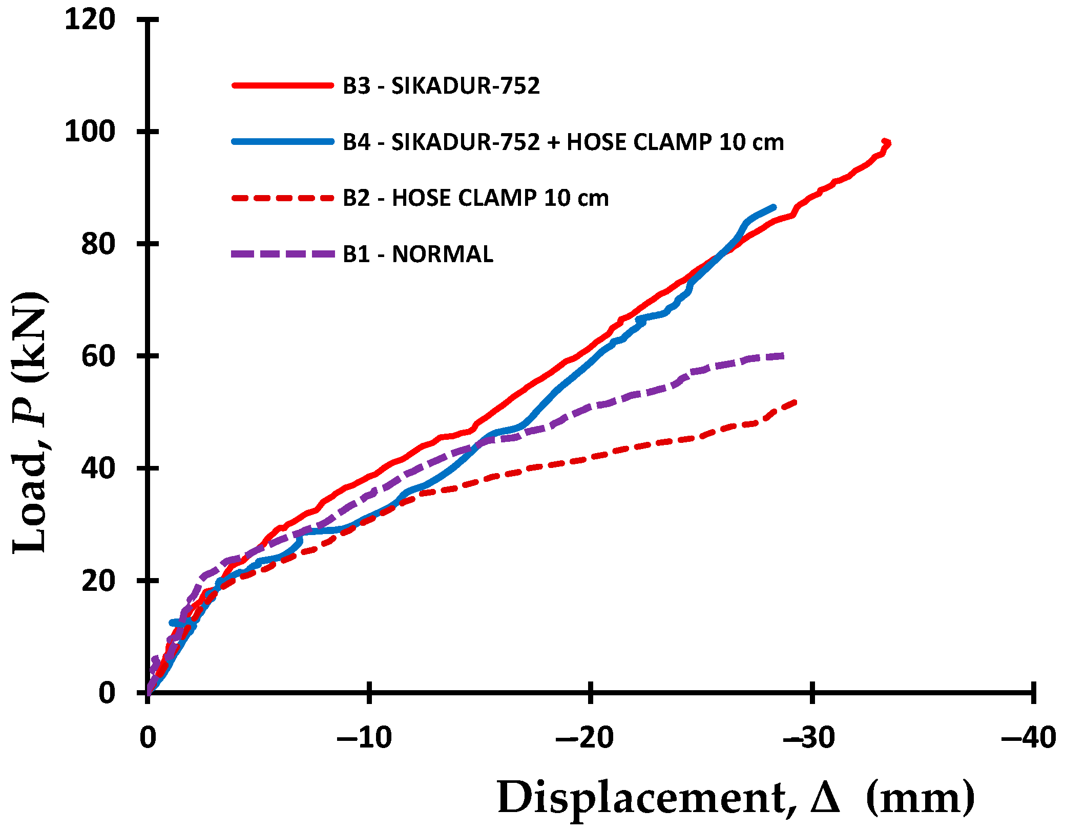
Muhtar [22] tested the flexural properties of four types of bridge beams with different treatments. The size of the bridge beam is 120 mm × 200 mm × 2100 mm with the area of tensile reinforcement ρ = 4.68% and compressive reinforcement ρ′ = 1.88%. Strengthening of bamboo reinforcement is done by applying adhesive as a waterproof layer. Modification of the roughness of the bamboo reinforcement is done by sprinkled sand and installing hose clamps on the tensile reinforcement. The test was carried out using the four-point load method. The position of the loading point is adjusted to the distance of the minibus car axle. The test results show that the bridge beam with bamboo reinforcement can reach the ultimate load of 98.3 kN with an initial crack load of 20 kN. Modification of the roughness of the bamboo reinforcement with adhesive, sand, and hose clamp can increase the bond stress and capacity of the bamboo reinforced concrete beam (BRC beam) [22]. The relationship between load vs. displacement is shown in Figure 1.
Testing of bridge trusses has been carried out by several researchers, including bamboo as reinforcement for a truss easel [39] and as reinforcement for a bridge frame with a span of 3 m [38]. Dewi and Wonlele [39] concluded that the collapse of the frame structure was caused by a combination of compressive and shear forces at the positioning of the support knot points. Failure at the knot placement causes the tensile and compressive rods to be unable to develop the maximum tensile and compressive strength; however, the collapse pattern still shows a bending effect [39].
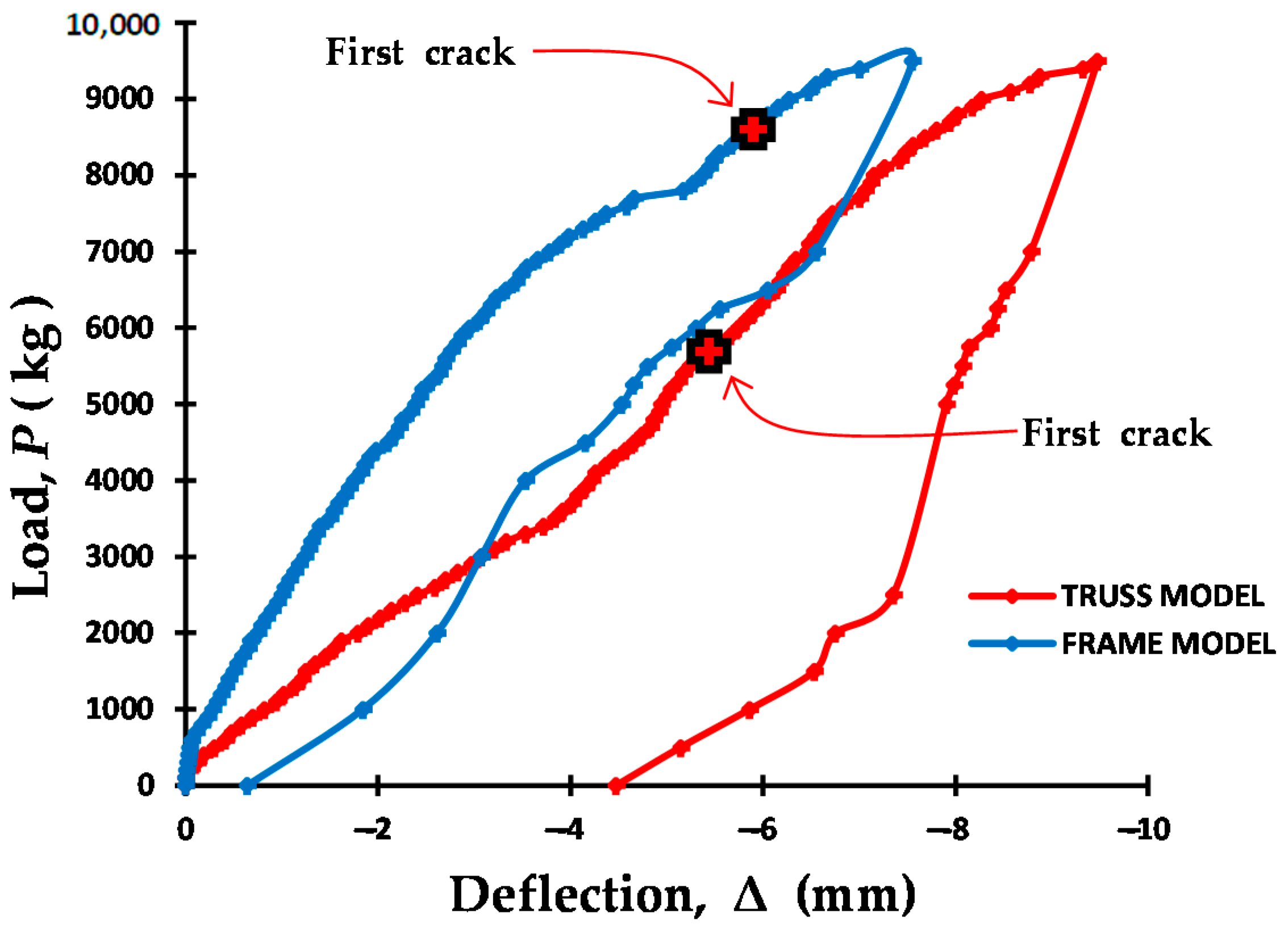
Muhtar et al. [38] tested two bridge frame models, namely one frame with symmetry reinforcement as the joint frame model or “truss model”, and one frame with flexural reinforcement as the rigid portal model or “frame model”. The test results show that the rigid portal model or “frame model” has a higher rigidity and load capacity than the joint frame model or “truss model”. The rigid portal model or “frame model” has an initial crack load capacity of 8700 kg or 87 kN and the joint frame model or “truss model” has an initial crack load capacity of 5500 kg or 55 kN. The relationship pattern of the load (P) vs. deflection (Δ) of the two bridge frames is shown in Figure 2.
The dimensions and reinforcement of the bridge beams used in this study are the same as Muhtar’s (2020) research [22]. In this study, strengthening of the reinforcement with hose clamps is only for tensile reinforcement, whereas in previous studies it was carried out for all reinforcements. Hose-clamp strengthening when the distance is too close together can reduce the elastic properties of the bamboo and reduce its capacity. The bridge frame model used in this study is a rigid frame model or “frame model” as in the experiment conducted by Muhtar et al. (2020) [38]. The reinforcement model on the lower side frame stem is installed with the concept of flexural reinforcement, whereas in previous studies it was carried out with the concept of truss reinforcement or symmetry, and their behavior shows flexural behavior. The basis for using the results of previous laboratory research is to control the results of the direct tests in the field. The novelty that is expected is (1) obtaining a prototype of the precast concrete reinforced concrete bridge; and (2) increasing the stiffness and capacity of the precast bridge elements when assembled into a complete unit. The expected benefits are that the research results can be used as the basis for the use of bamboo as a substitute for steel reinforcement, which could be applied to a simple frame bridge structure in underdeveloped village areas with local materials that are cheap, environmentally friendly, and acceptable.
The targets to apply this research to are underdeveloped villages with lots of bamboos. Bamboo is a new and renewable energy from natural resources that are very abundant in rural areas. Bamboo needs to be used, including for reinforced concrete. The use of bamboo is one of the real efforts to increase the economic strength of the community. Based on previous research and the abundant potential of bamboo, it is necessary to use it as a reinforcing element for simple precast reinforced concrete bridges, especially in rural areas with lots of bamboos.
2. Materials and Methods
2.1. Materials
The bamboo used was the petung bamboo (Dendrocalamus asper), aged 3–5 years [13,23]. For the petung bamboo, the bamboo shoots are purplish-black, covered with hairs that are velvety brown to blackish. Petung bamboo is large, with a segment length 40–50 cm, diameter 12–18 cm, and a stem height of up to 20 m. The nodes are surrounded by aerial roots. The wall thickness of the bamboo internode is between 11 and 36 mm, as per Brink (2008) in Wikipedia Indonesia (2016) [2]. The mechanical properties of petung bamboo are shown in Table 1. The tensile test for bamboo petung was based on ASTM D 143-94 [40].
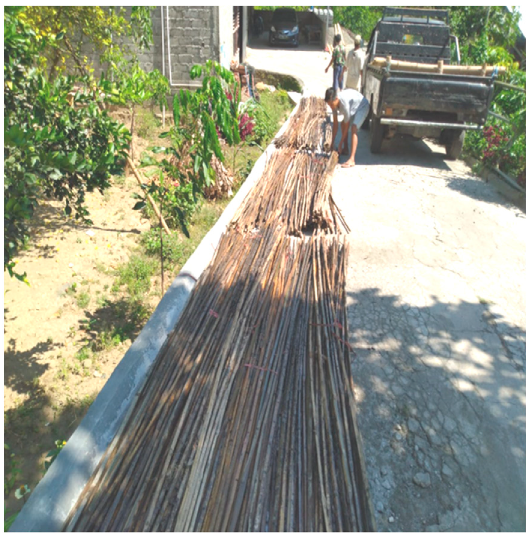
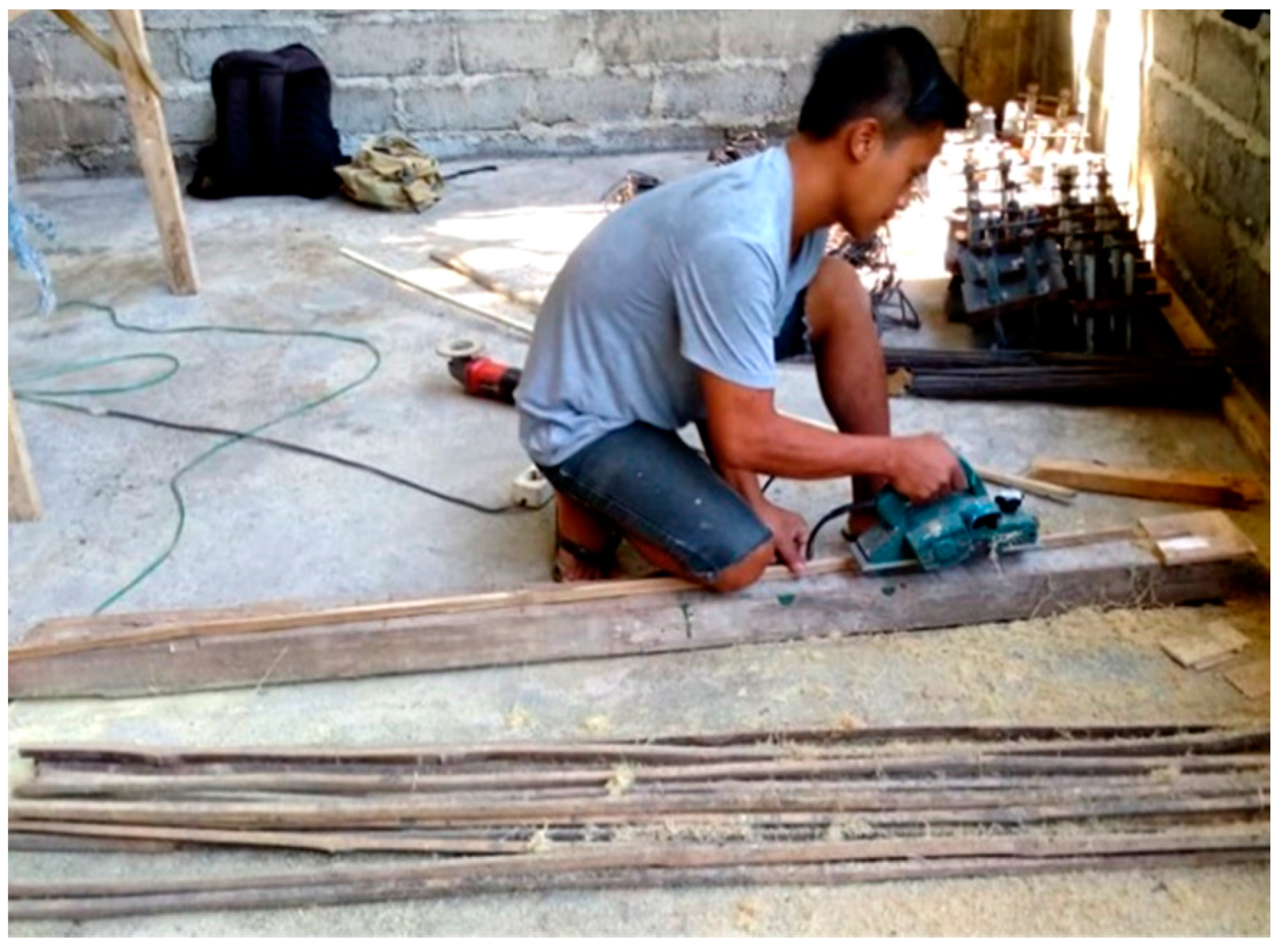
The bamboo part that is taken was 6–7 m from the base of the bamboo stem. The bamboo was cut and split into a bamboo reinforcement size of 15 × 15 mm2. The bamboo to be used must be treated with the following steps: (a) the bamboo must be cut and split close to the size of the bamboo reinforcement to be used, namely 15 mm × 15 mm × 2000 mm for bridge beam reinforcement, and 15 mm × 15 mm × 3160 mm for the lower side truss bridge reinforcement. Meanwhile, the reinforcement for the vertical truss is 15 mm × 15 mm × 1100 mm, the top stem is 15 mm × 15 mm × 1100 mm, and the diagonal stem is 15 mm × 15 mm × 1300 mm; (b) the bamboo must be soaked in water for 1–2 months to remove the sugar content and prevent termites and insects, as shown in Figure 3 [9]; (c) it should be dried in free air until the moisture content is approximately 12%, as shown in Figure 4; (d) the bamboo reinforcement should be trimmed with a grinding machine according to the specified size, as shown in Figure 5; (e) one should provide a waterproof layer to reduce the occurrence of the hydrolysis process between the bamboo and concrete, as shown in Figure 6; (f) do sand sprinkling to modify the roughness of the bamboo reinforcement, as shown in Figure 7; and (g) stringing the bamboo reinforcement, as shown in Figure 8.
Ghavami (2005) [1] and Agarwal et al. (2014) [13] concluded that the best waterproof layer is Sikadur 32 Gel. Muhtar (2019) [8] treated bamboo with Sikadur®-752 and a hose clamp. The test results show that the adhesion strength increases up to 200% and the beam capacity increases 164% when compared to untreated bamboo reinforcement. The waterproof or adhesive layer used here was Sikadur®-752, produced by PT Sika Indonesia [8,27]. Sikadur®-752 is a solvent-free, two-component, super-low viscosity liquid, based on high strength epoxy resins—especially for injecting into the cavities and cracks in concrete. Usually used to fill and seal cavities and cracks in structural concrete, Sikadur®-752 is applied to the bamboo reinforcement to prevent water absorption. The effectiveness and durability of Sikadur®-752 adhesives require further research. The specifications of Sikadur®-752 are shown in Table 2. The coating was carried out in two stages. The second waterproof layer was applied to perfect the waterproof layer of the first stage. The thermal effect of Sikadur®-752 on bamboo reinforcement can be prevented by the moisture content of 12% in bamboo. In determining the strength of the bamboo, a 12% moisture content in the air-dry condition has been considered as a reference standard [42], and the temperature does not significantly affect the loss of stiffness [43]. Chemical treatment of bamboo helps increase the durability of the bamboo fibers and reduces the moisture absorption of the bamboo fibers [44].
The hose clamp used had a diameter of ¾”, made in Taiwan [8,22]. The shear reinforcement of the bridge beam and bridge frame uses steel of 6 mm in diameter, with a fy 240 MPa quality. From the results of the bamboo tensile test in this study, it was found that the modulus of elasticity of the bamboo (Eb) was 17,236 MPa, with a tensile strength of 127 N/mm2 [8], and the modulus of steel elasticity (Es) was 207,736 MPa [8]. The concrete mixture used was Portland Pozzolana Cement (PPC), with a pH of 7, as well as sand, coarse aggregate, and water with a mixed proportion of 1.81:2.82:0.52, as shown in Table 3. The average compressive strength of the concrete was 31.31 MPa at the age of 28 days. The process of treating the bamboo to assembling the bamboo reinforcement can be seen in Figure 3, Figure 4, Figure 5, Figure 6, Figure 7 and Figure 8.
2.2. Methods
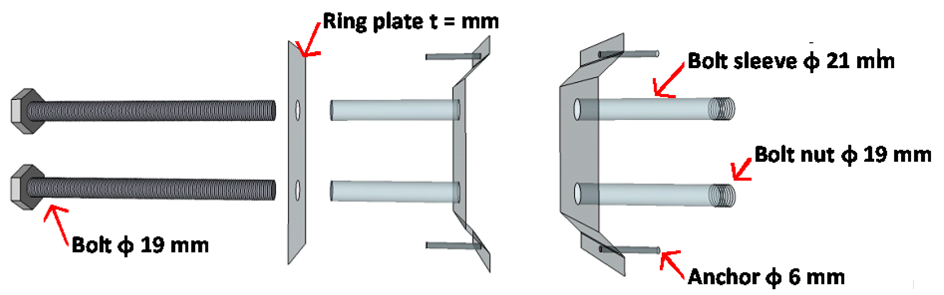
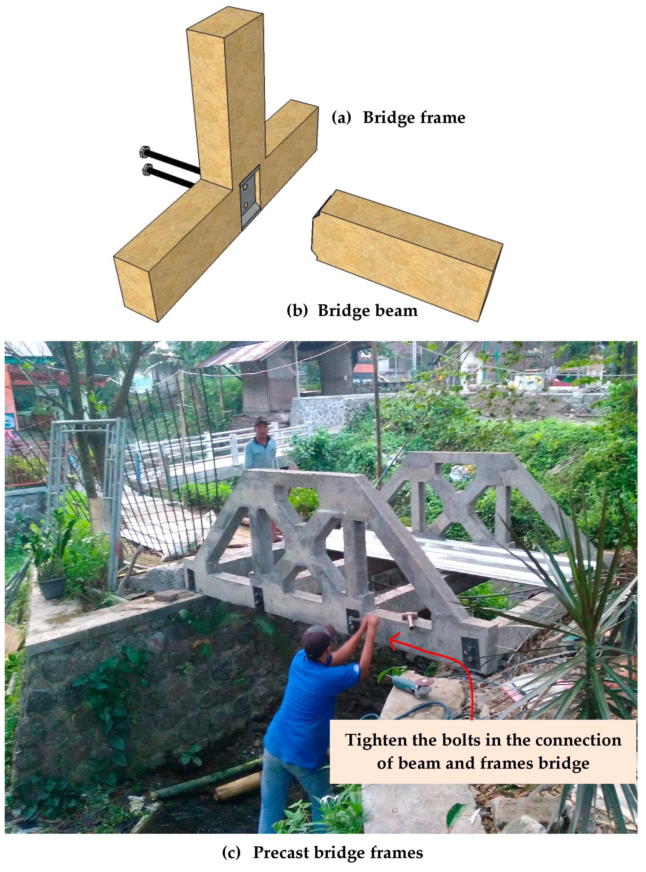
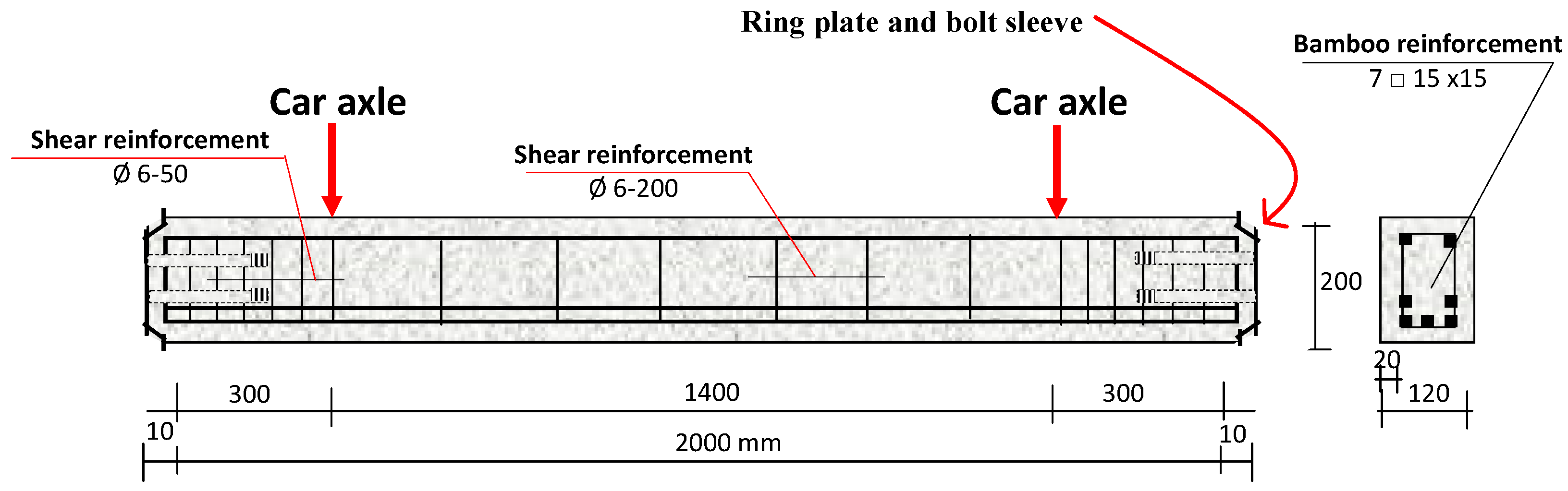
The dimensions of the bridge were a span of 320 cm, a width of 224 m, and a frame height of 115 cm. The clean span of the inside of the bridge was 280 cm. Two bridge frames were connected by four bridge beams. Each end of the bridge beam was connected to the knot point with two bolts and a steel ring plate with a thickness of 2 mm to prevent stress concentration. Details and models of the joints between the beam and precast bridge frame are shown in Figure 9 and Figure 10. The bridge supports were made of reinforced concrete with the assumption of hinge support and a rubber bearing assuming roller support. The bridge plate was a 10-cm-thick concrete plate with 0.3-mm-thick spandex. The shape and model of the precast bridge of the bamboo reinforced concrete frame are described in Figure 11. Details of the reinforcement of the precast bridge beams are shown in Figure 12. Details of the reinforcement of the bridge frame are shown in Figure 13 and Figure 14 and Table 4.
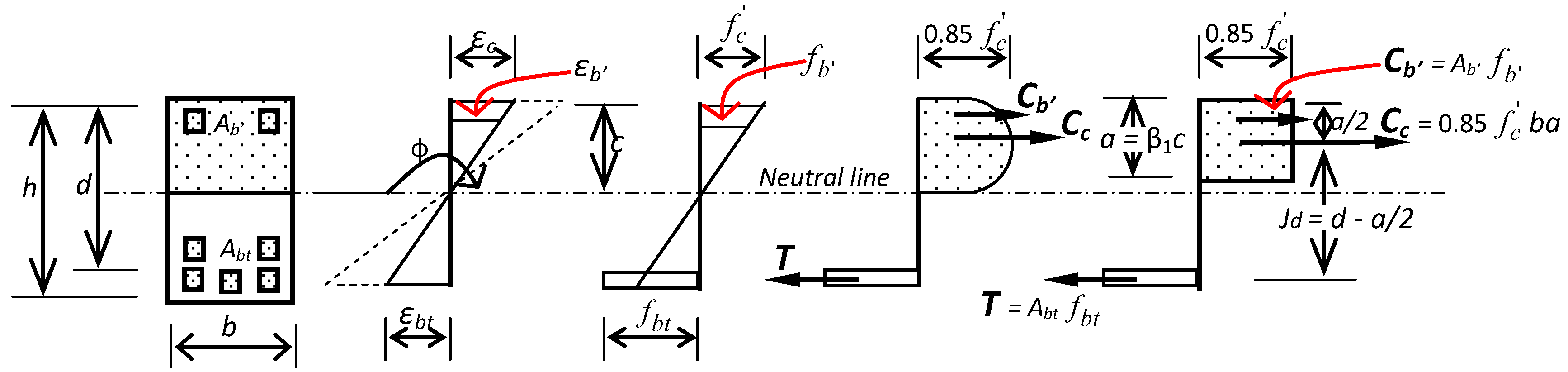
The design concept of the bamboo reinforced concrete beams follows Ghavami (2005) [1] and Muhtar (2020) [22], as shown in Figure 15. The balance of the concrete compressive force (C = Cb′ + Cc) and the tensile force (T) must be met, as shown in Figure 15. The tensile strength of the bamboo reinforcement (T) was obtained by multiplying the bond stress with the shear area in the bamboo reinforcement. The failure of the bamboo reinforced concrete beams was due to the breaking of the bonds between the bamboo and concrete.
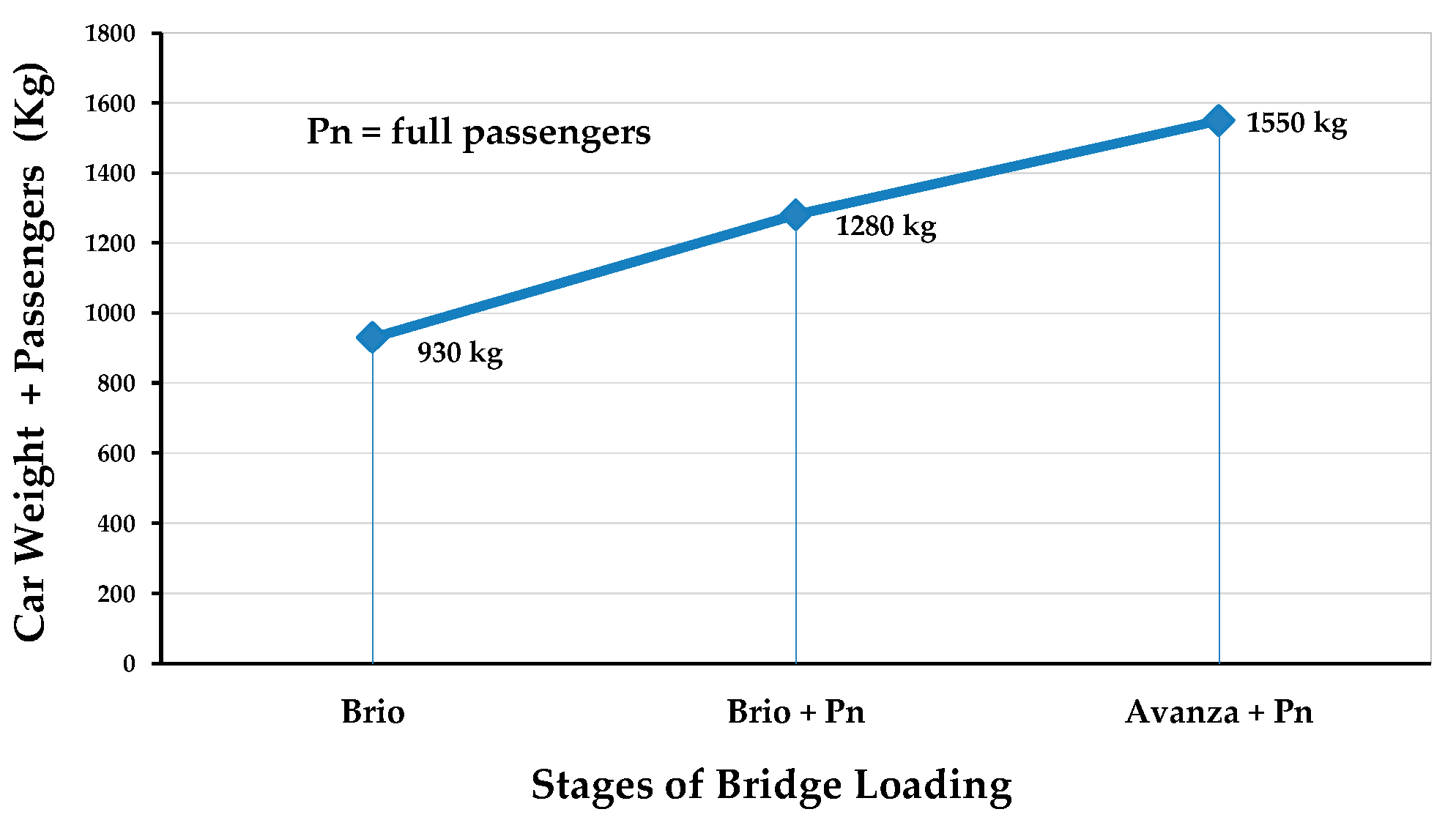
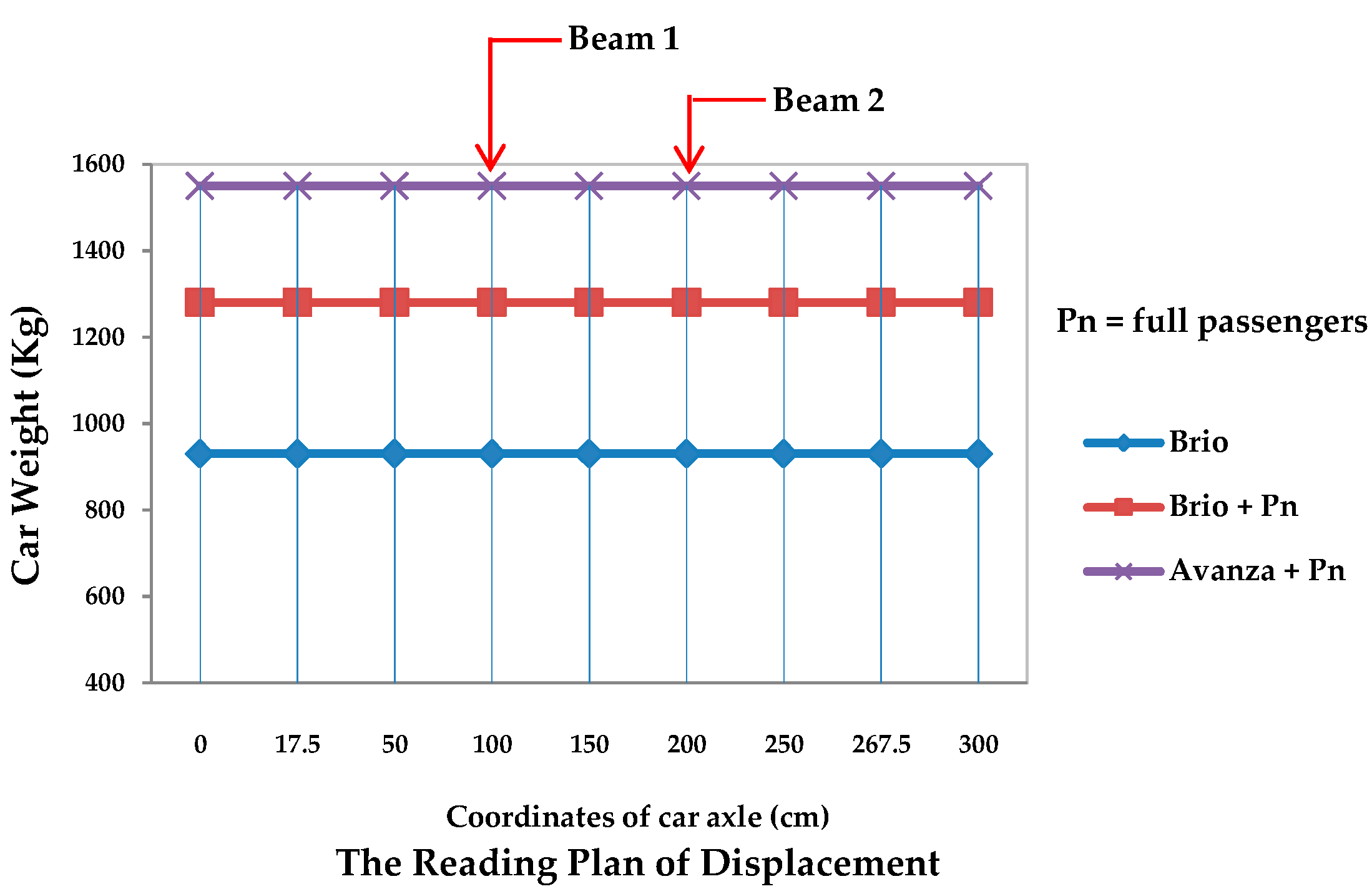
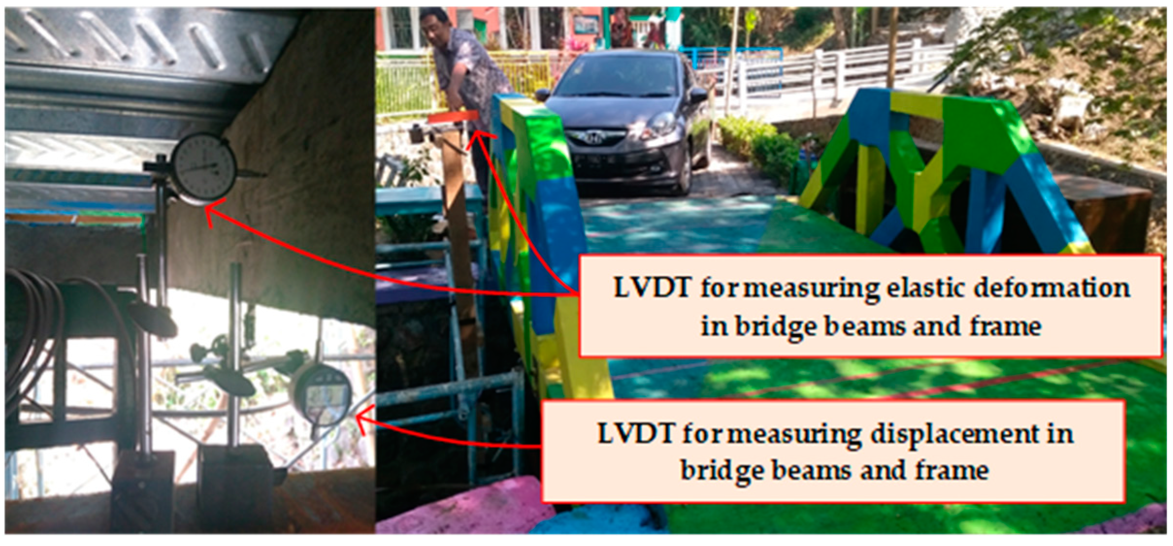
Testing of the precast bridges with the bamboo reinforced concrete frames was carried out directly with a load of a minibus-type vehicle. The load was given in stages and levels, starting from a zero load, Brio carload without passengers, Brio carload full of passengers, and Avanza carload full of passengers, as shown in Figure 16. The stage of reading the response variable was carried out when the axle of the car was at the coordinates 0 cm, 17.5 cm, 50 cm, 100 cm, 150 cm, 200 cm, 250 cm, 267.5 cm, and 300 cm from the support, as shown in Figure 17. Tests were carried out on service limits or elastic conditions with displacement and deformation measuring parameters. To get the displacement that occurs in the beam and bridge frame, four LVDTs (Linear Variable Displacement Transducers) were installed with inductive transducers of type PR 9350 in the middle of the frame span and the middle span of the bridge beam. Meanwhile, to determine the deformation of the bridge, six pieces of LVDTs were installed, two pieces of LVDTs were installed in the middle of the side frame span, and four LVDTs were installed on the side of the four ends of the beam. The performance test settings for the precast bridges of the bamboo reinforced concrete frames are described in Figure 18.
The weights of the Brio and Avanza cars were calculated based on the empty weight and the total passenger weight according to the capacity of the number of passengers. The calculation of passenger weight was based on the average weight of Indonesians, namely 65 kg. The calculation of the total weight of a minibus and its specifications are shown in Table 5.
The planned life of the bridge is 10 years. The determination of the age of the bridge in this study is based on opinions and research on the resistance of bamboo as concrete reinforcement that has been carried out by several researchers, including Hidalgo (1992) in Sattar (1995) [46], Ghavami (2005) [1], Rong (2007) [47], and Lima Jr et al. (2008) [14]. After the design life of the bridge is reached, a gradual visual observation of the deflections and cracks will be carried out. Observations will be carried out every year with the main objective of observing the durability of bamboo as the concrete reinforcement of the bridge elements. Measured parameters during the observation period are deflection and cracks that may occur due to the decreased durability of bamboo reinforcement.
Hidalgo (1992) in Sattar (1995) [46] reported that a house in Colombia whose ceiling and walls are made of bamboo plastered with cement mortar can last for more than ninety years. Ghavami (2005) [1] mentions that, after testing, the bamboo reinforced concrete beams were left in the open air at the PUC Rio Brazil university campus; the bamboo reinforcements from the treated beams showed that the bond with the concrete was still in satisfactory condition after 15 years. Rong (2007) [47], in his opening speech at the First International Conference On Modern Bamboo Structure (ICBS-2007) in Changsha, China, stated that the bamboo reinforcement that is used as a substitute for steel reinforcement in precast floor plate elements for a five-story office building still functions well after more than fifty years of use, so bamboo reinforcement can be used as a substitute for steel reinforcement as the level of durability is good. Lima Jr et al. (2008) [14] experimented on the Dendrocalamus giganteus bamboo species, showing that bamboo with 60 cycles of wetting and drying in a calcium hydroxide solution and tap water did not decrease its tensile strength or Young’s Modulus. This is an important factor in the material for use as concrete reinforcement.
2.3. The Numerical Method Used
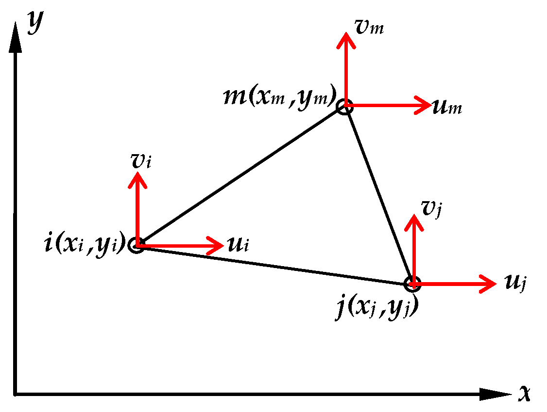
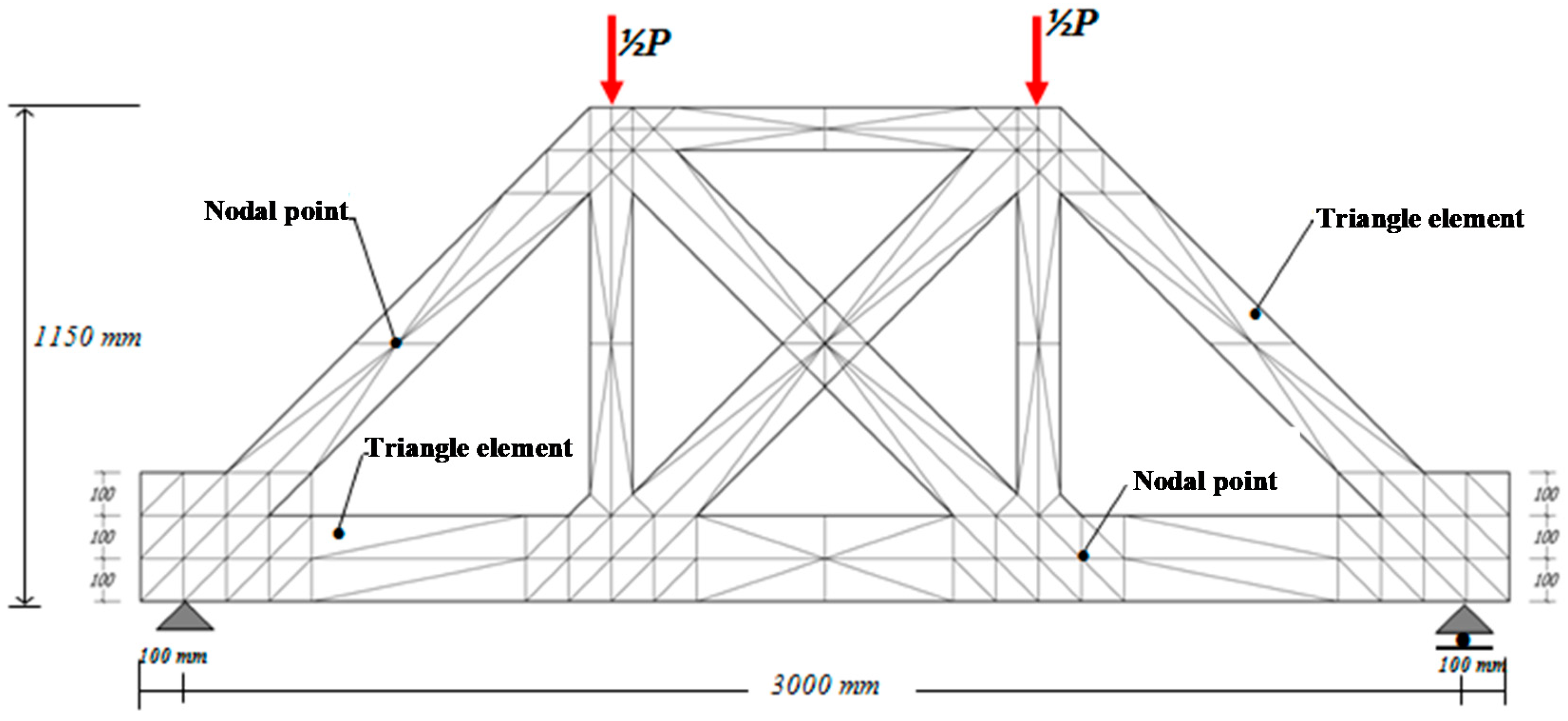
Determining the capacity and behavior of reinforced concrete structural elements can be done with a numerical approach. Theoretical analysis is carried out as control over the results of research in the laboratory so that the actual structural behavior differences can be seen with the theoretical analysis. The numerical method used is the finite element method (FEM). Numerical verification in this study was carried out to control the suitability of the deflection value of the experiment results with the deflection contours of the FEM analysis result. The program developed in the FEM analysis was written with the Fortran PowerStation 4.0 program. The theoretical analysis to calculate the load causing the initial crack was done by using the elastic theory with the transformation section. The formula for the transformation of the cross-sectional bamboo reinforced concrete is shown in Equations (1) and (2). For linear analysis, the material data entered are the Poisson’s ratio (υ) and the modulus of elasticity (E). The constitutive relationship analysis of the problem-solving method uses the stress-field theory. Triangular elements are used to model the plane stress element with a two-way primary displacement at each nodal point so that the element has six degrees of freedom, as shown in Figure 19. The stress–strain relationship for the field stress problem has the form of an equation, such as Equation (3).
where E is the modulus of elasticity and ν is the Poisson’s ratio. The principal stresses in two dimensions are calculated by Equation (4). The Fortran PowerStation 4.0 programming language for triangle elements is shown at the following link: https://bit.ly/3l1oU0d.
3. Results
Specifications for precast bridges of the bamboo reinforced concrete frame are shown in Table 6. The precast bridges were tested with a minibus car full of passengers. The test was carried out after several stages of work were done, including making river stone foundations, making support plates, setting the frame on two supports, installing bridge beams and joints, casting bridge plates, and completing or finishing the bridge. Recording of the test results started when the front axle of the minibus car was right on the hinge support and ended when the rear axle of the minibus car was right on the support of the roller. The test result data are shown in Table 7.
The security measure during the test was to place the support poles and scaffolding under the bridge. The support poles and scaffolding under the bridge also function as a place and safety for the LVDT tool. Besides, the bridge was planned using the “Service Load Planning” method with the assumption that the structure has linear elastic behavior and the load test was carried out with elastic loads or under the initial crack load of the most critical bridge components. Observation of deflection and the deformation that occurred was deflection and elastic deformation. The critical load (Pcr) or initial crack load was 2.1 tons and the maximum test load for the minibuses was 1.55 tons.
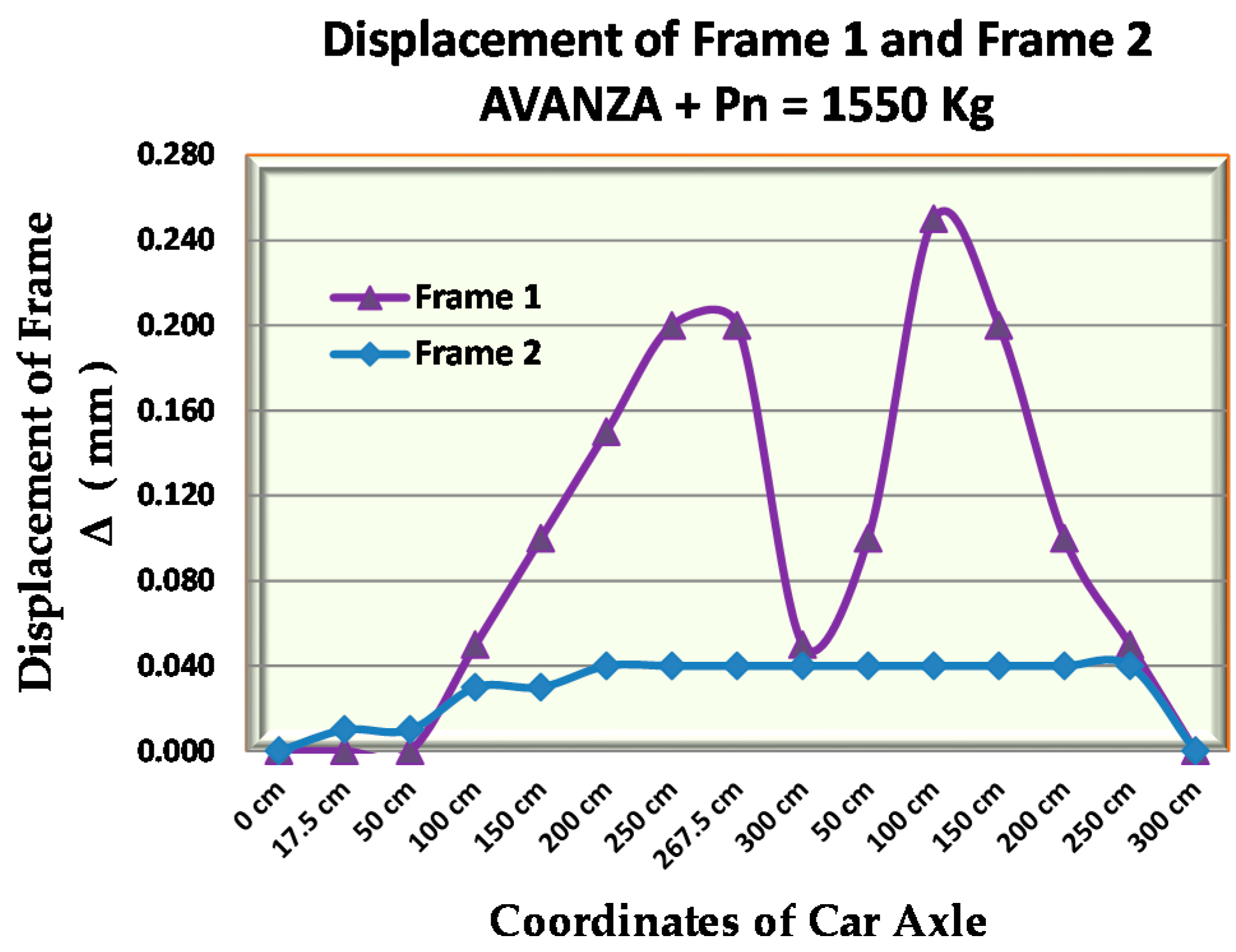
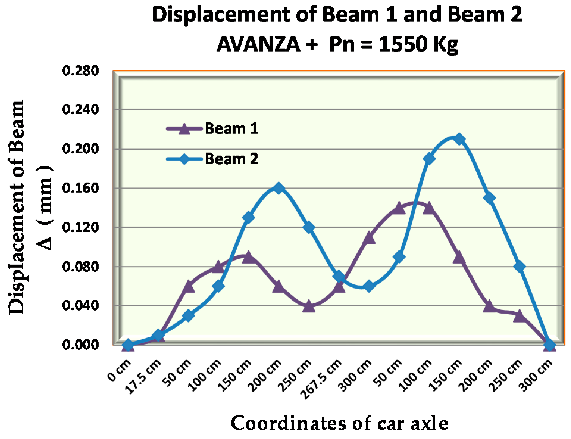
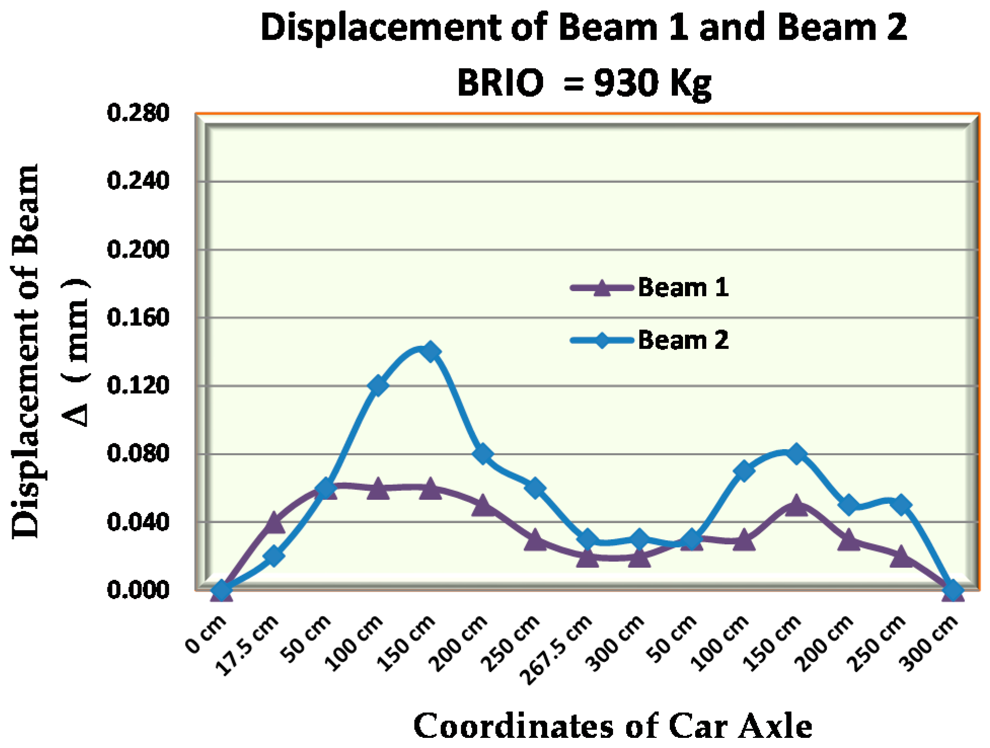
Figure 20, Figure 21, Figure 22, Figure 23, Figure 24 and Figure 25 show the beam displacement and the bridge frame with the minibus Brio car, the Brio full of passengers, and the AVANZA full of passengers. The maximum displacement with the load of the Brio car occurred when the position of the front axle was at coordinates 150 cm and the rear axle was at a distance of 85 cm from the pedestal, with a displacement of 0.2 mm for the frame and 0.14 mm for the beam displacement. While, the maximum displacement with a full passenger Brio car occurred when the position of the front axle was at coordinates 200 cm and the rear axle was at a distance of 35 cm from the pedestal, with a displacement of 0.2 mm for the frame and 0.17 mm for the beam displacement. The maximum displacement with a full passenger AVANZA car load occurred when the front axle position was outside the bridge coordinates, which was 115 cm from the roller support, and the rear axle was at 150 cm coordinates, with a displacement of 0.25 mm for the frame and 0.21 mm for the displacement beam.
Based on the AASHTO [48] and RSNI T-12-2004 standards [49], the maximum allowable displacement limit of the bridge is Δmax = L/800 or equal to 3.75 mm. Thus, the maximum displacement that occurs in the element of the bamboo reinforced concrete frame bridge meets the requirements based on the AASHTO [48] and RSNI T-12-2004 standards [49].
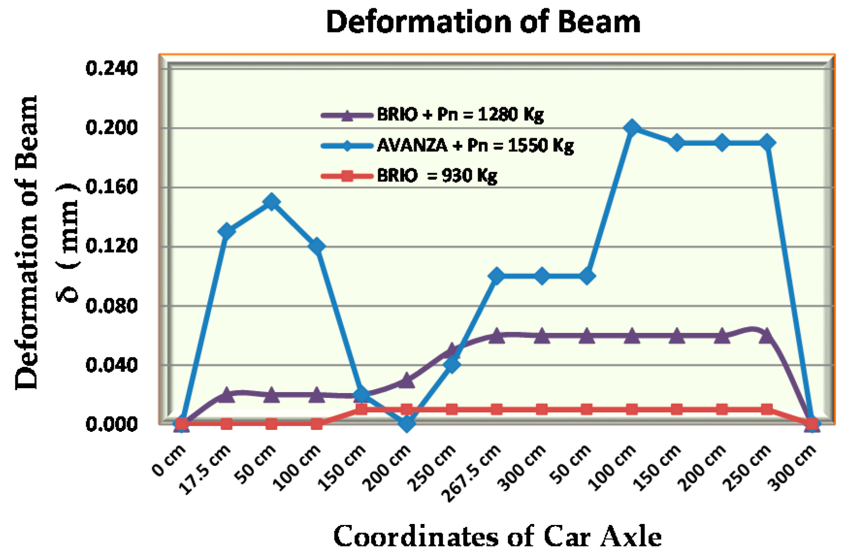
Figure 26 shows the deformation of the bridge beam of the bamboo reinforced concrete with a load of Brio minibuses, the Brio car full of passengers, and the Avanza car full of passengers. From Figure 26 and Table 7, we see that the maximum deformation occurs in the beam with the load of the Avanza car with a full passenger load, which is when the position of the front axle is outside the coordinates of the bridge, which is 65 cm from the roller support, and the rear axle is at coordinates 100 cm, with the deformation of the beam being 0.20 mm.
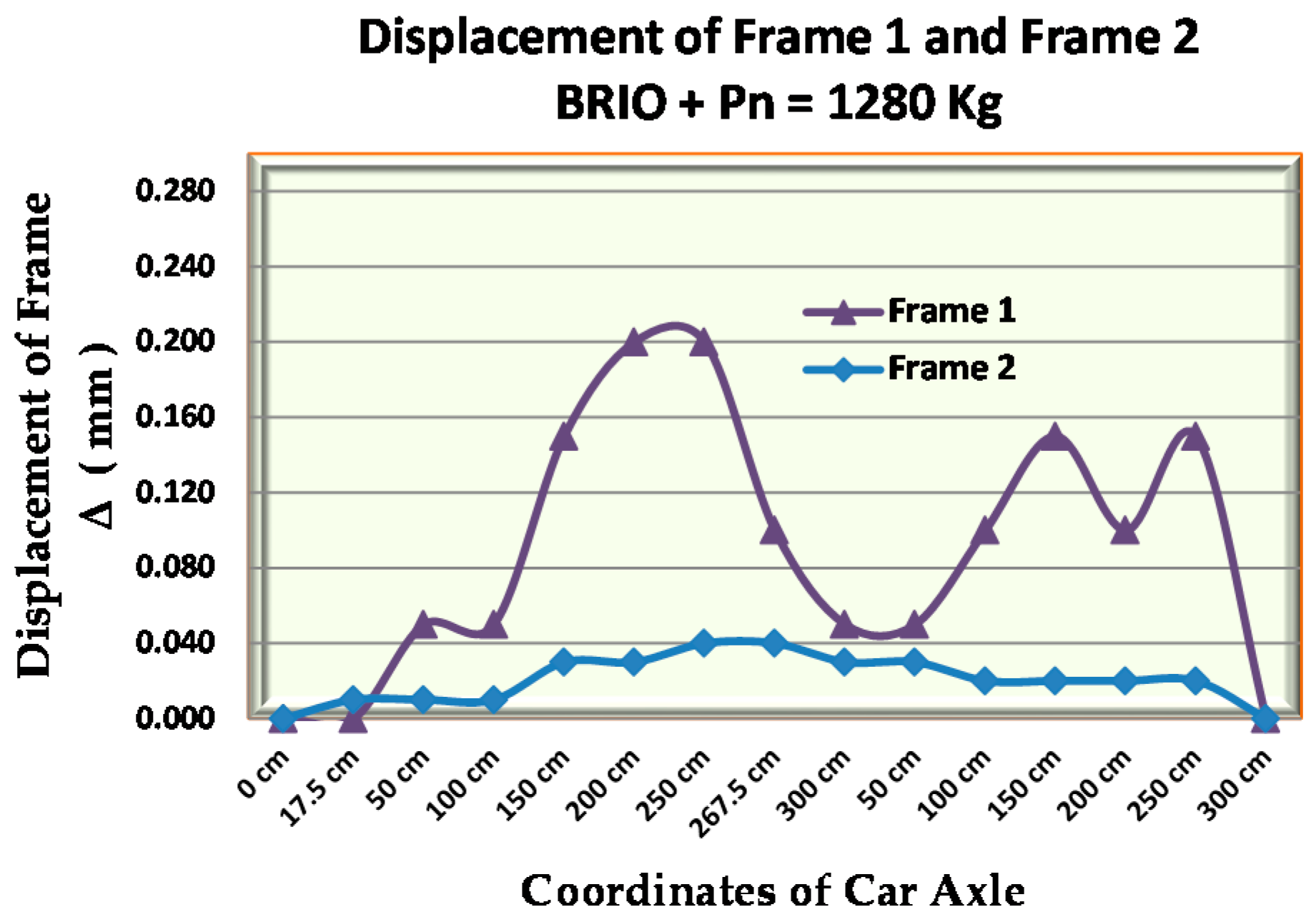
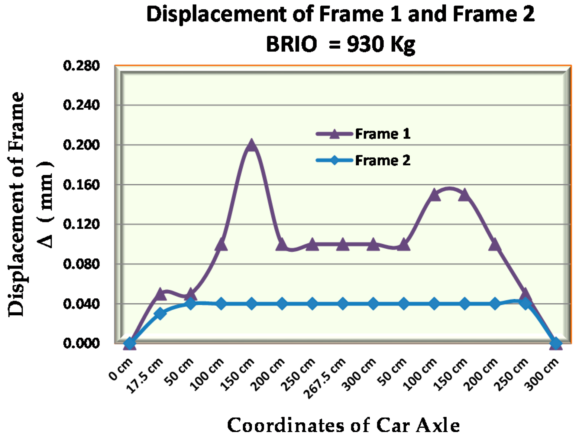
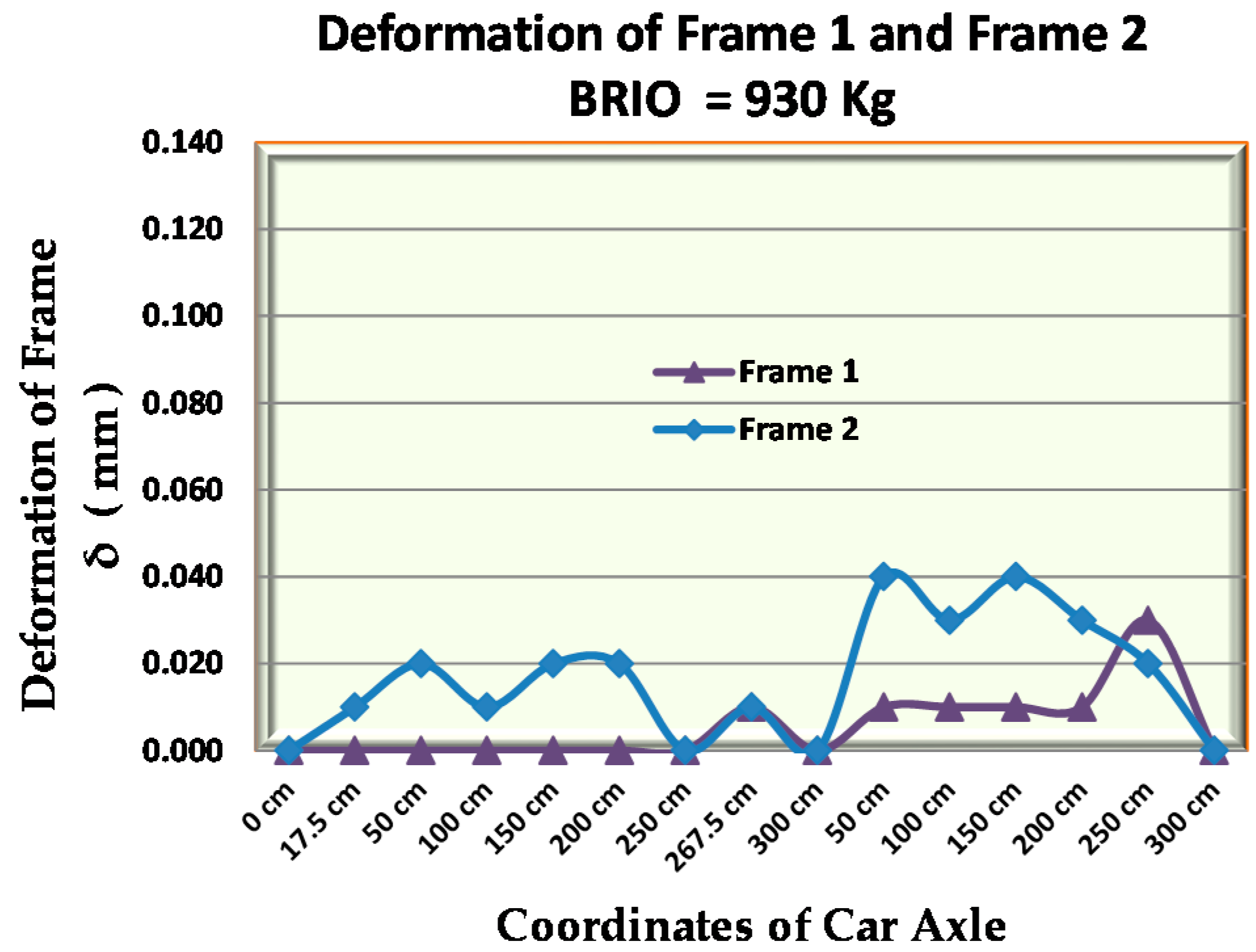
Figure 27, Figure 28 and Figure 29 show the deformation of the bridge frame with the load of the Brio minibus, Brio car full of passengers, and the Avanza car full of passengers. The maximum deformation with the brio car load occurs when the position of the front axle is outside the coordinates of the bridge, which is 85 cm from the roller support, and the rear axle is at coordinates 150 cm, with a frame deformation of 0.04 mm.
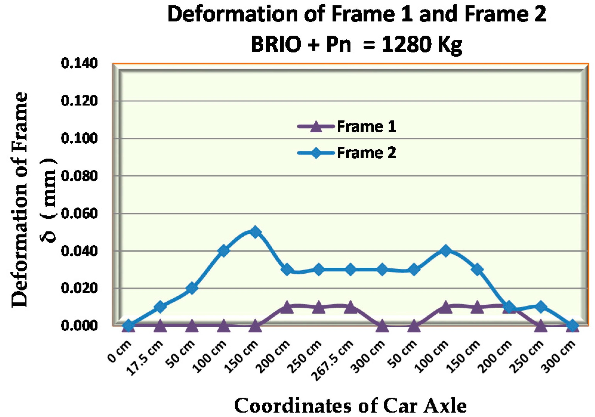
The maximum frame deformation with the load of the brio car full of passengers occurred when the position of the front axle was at coordinates 150 cm and the rear axle was at a distance of 85 cm from the hinge support, with a deformation of 0.05 mm. The maximum deformation of the frame with the load of the Avanza car full of passengers occurred when the position of the front axle was at the coordinates of the bridge of 150 cm, and the rear axle was at a distance of 115 cm from the hinge support, with a deformation of 0.13 mm.
4. Discussion
Deformation usually occurs due to shrinkage of concrete, deformation of precast connections, foundation settlement, or due to a static load or dynamic loads on the bridge. In this study, deformation or elastic deformation is a change in shape or change in the angle of the cross-section of the beam or frame due to the distribution of the vehicle loads within the elastic limit measured in the horizontal direction of the cross section. Measurements were made by installing LVDTs (Linear Variable Displacement Transducers) with inductive transducers of type PR 9350 on the horizontal side of the frame and bridge beams, as shown in Figure 30.
The accuracy of the deformation measurement is very much determined by the calibration of the equipment, the accuracy of the load point of the observation, the conditions of the test site, such as near roads, and human error. Figure 26 shows that the minimum beam deformation occurs when the car axle is right on the neutral line of the beam; this shows that the coupling moment or torque due to the load is a factor that greatly affects the size of the beam deformation. Gravity loads right on the neutral line can reduce the deformation and increase the deflection of the bridge beams. Figure 21 and Figure 26 at the 200 cm coordinates show that when the beam deformation is minimum, the beam displacement is maximum. As shown in Figure 17, Beam 1 is at the coordinates 100 cm and Beam 2 is at coordinates 200 cm. The deformation of the beam increases in line with the track of the car axle; that is, the deformation continues to increase, respectively, at the front car axle and rear car axle. However, the accuracy of the deformation measurements needs attention as to the many determinants of accuracy that exist.
Figure 27 and Figure 28 shows that the minimum frame deformation or deformation = 0 occurs when the car axle is directly above the pedestal or approaching the pedestal. Meanwhile, the maximum frame deformation occurs when the car axle is in the middle of the bridge span, which is at coordinates 150 cm. There is a difference in the deformation of the bridge beam and the bridge frame, namely the maximum beam deformation occurs when the load is outside the beam coordinates, while the maximum frame deformation occurs when the load is in the middle of the bridge span or at the 150 cm coordinates. It must be remembered that careful preparation at the time of testing or measurement must be considered so that the data obtained is truly accurate; as shown in Figure 27, the coordinates at 250 cm convey inconsistent deformation data even though the car axle is close to the support.
Table 7 shows that the maximum deformation of the bridge frame is 0.13 mm and the maximum displacement of the bridge beam is 0.20 mm. According to the AASHTO [48] and RSNI T-12-2004 standards [49], the allowable limit for the maximum displacement is Δmax = L/800 = 3.75 mm and the maximum deformation of the bridge is δmax = L/800 = 3.75 mm. Thus, the maximum deformation and displacement that occurs in the precast bridge elements of the bamboo reinforced concrete frame meet the requirements based on AASHTO [48] and RSNI T-12-2004 standards [49]. However, the relationship of load vs. displacement of the beam and the frame results from the field experiments need to be validated or controlled with the relationship of load vs. displacement of laboratory experimental results and simulation results of numerical methods. The simulation in this study used the finite element method (FEM).
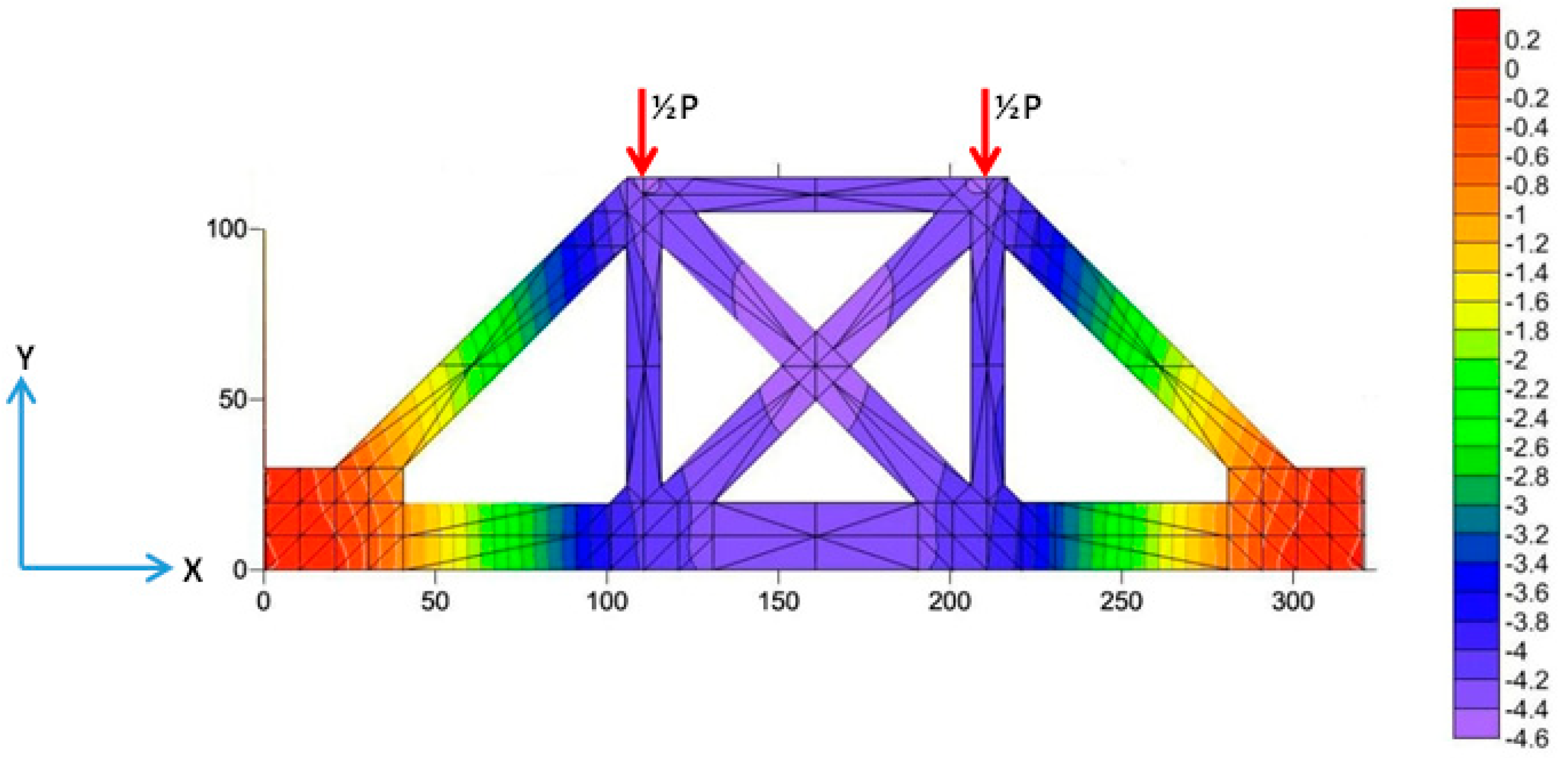
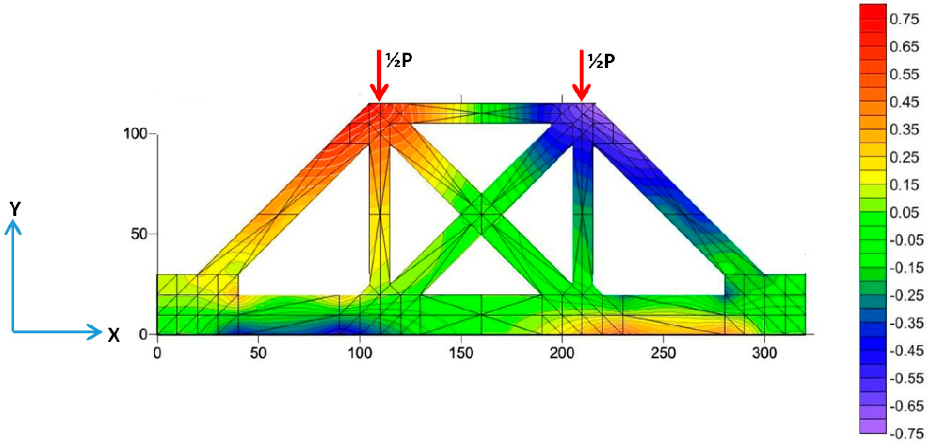
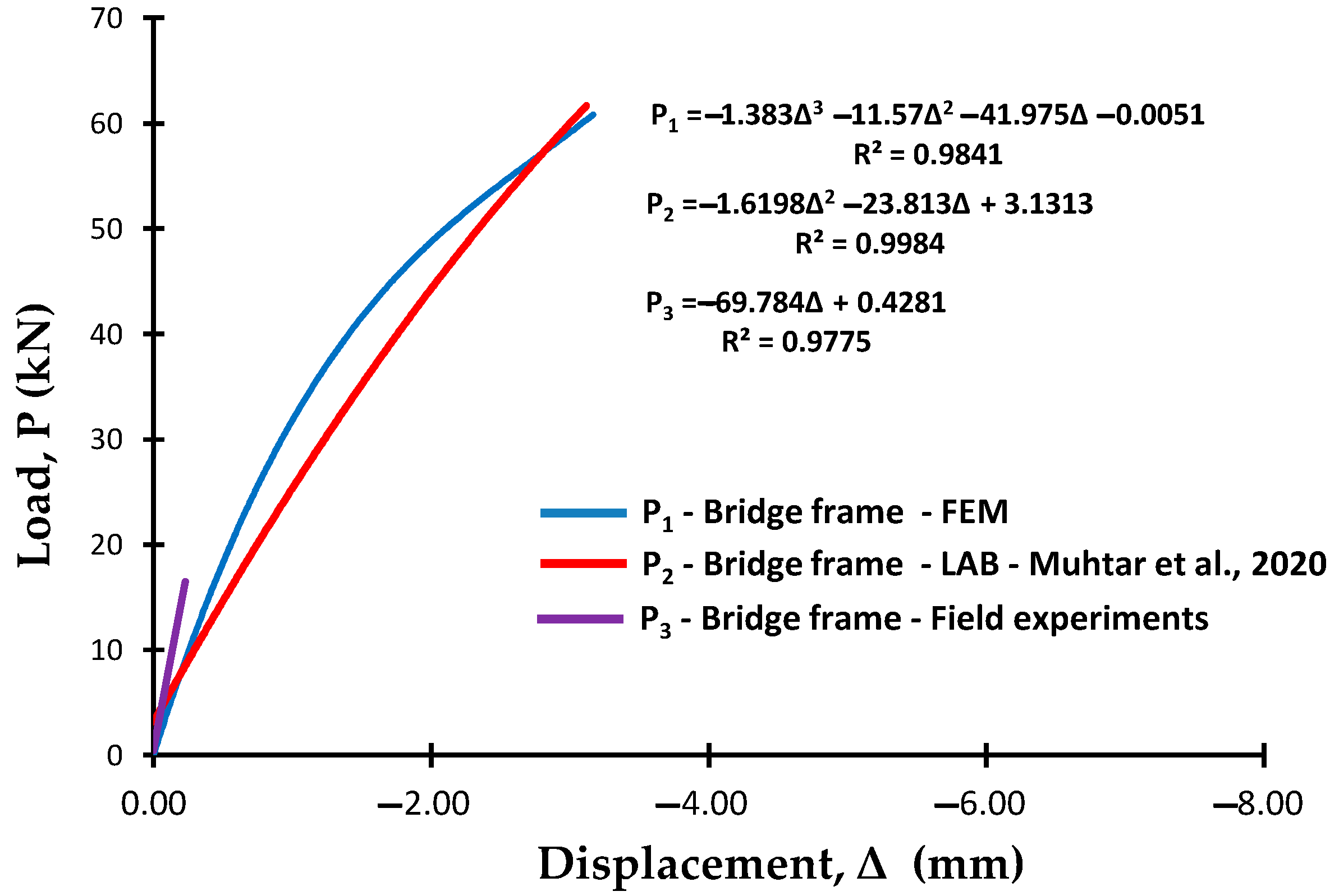
The simulation of the bridge frame test using the finite element method (FEM) was carried out using the Fortran PowerStation 4.0 program and Surfer 9.8 software [50] based on laboratory test results. Simulations were carried out as control and validation of the experimental data. The bridge frame test simulation was carried out at the first crack load stage, which was 87 kN based on the frame loading capacity of only 100 kN. The discretization of the bamboo reinforced concrete bridge frame for the finite element method (FEM) is shown in Figure 31. The Y-direction and X-direction displacement are shown in Figure 32 and Figure 33. The loading stages and Y-direction displacement of the finite element method simulation results are combined with the load vs. displacement laboratory test results [38], and with the field test results as shown in Figure 34. Figure 33 shows displacement in the X-direction; the green color shows the minimum displacement, and the orange and blue colors show the maximum positive and negative displacement, respectively. FEM analysis modeling on the bamboo reinforced concrete frames can be seen in Item 2.3 of the numerical method used.
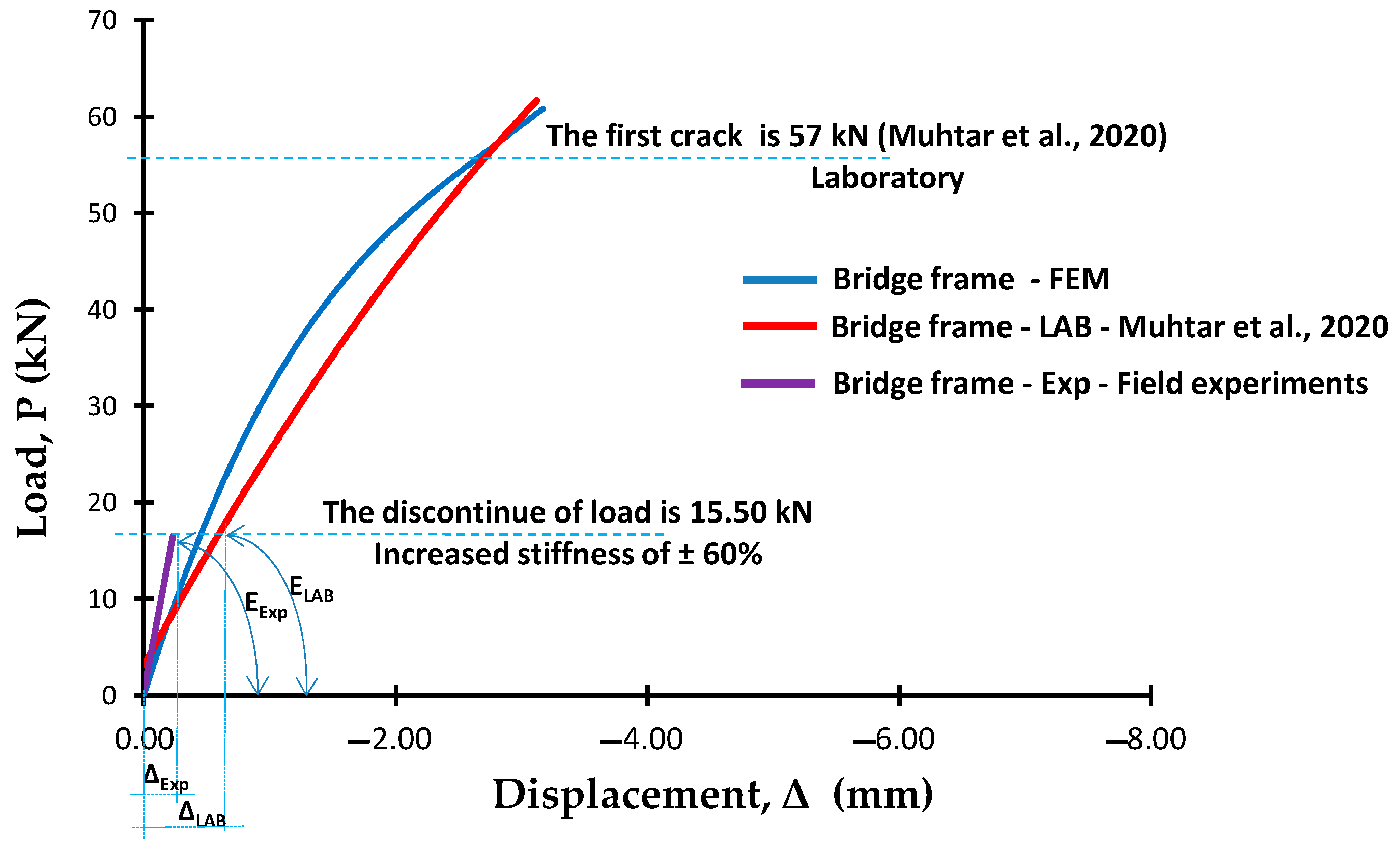
Bridge integrity is the ability of a bridge structure or bridge components to withstand the designed load, preventing structural collapse due to cracks or fractures, deformation, and structural fatigue. Structural integrity is a concept used for the design plan and designing service load. Stiffness is the main parameter of the resistance of a bridge structure to get good bridge integrity [24]. The stiffness of the elements of the bridge structure needs to be controlled to prevent sudden collapse due to cracking and excessive deformation. Stiffness control of the beams and bridge frames was analyzed through a combination of load vs. displacement from the simulation results of the finite element method (FEM), the results of laboratory experiments [22,38], and the results of field experiments as shown in Figure 34. Control was carried out at the maximum load point of the bamboo reinforced concrete precast frame bridge test in the field, which was 15.5 kN, as shown in Figure 35 and Figure 36. Documentation of the direct test of the bamboo reinforced concrete precast bridges can be seen at the following link: https://bit.ly/3gzaW30.
Calculation of the aerodynamic effects due to wind loads and dynamic analysis on precast concrete bamboo bridges were not carried out. Based on the Earthquake Resistance Standard for Bridges, the SNI SNI-07-SE-2015 [51] dynamic analysis needed to be carried out for bridge types with a complex behavior, one of which was the main span exceeding 200 m. In this study, the bridge width is 2.24 m and the bridge span is 3.20 m, and the ratio of the bridge width to the bridge span of 0.7 is still stable against aerodynamic effects due to wind loads according to Leondhart’s requirements (B ≥ L/25) and still meets the maximum deflection requirements of AASHTO [48] and RSNI T-12-2004 [49], which is Δmax = L/800 = 3.75 mm.
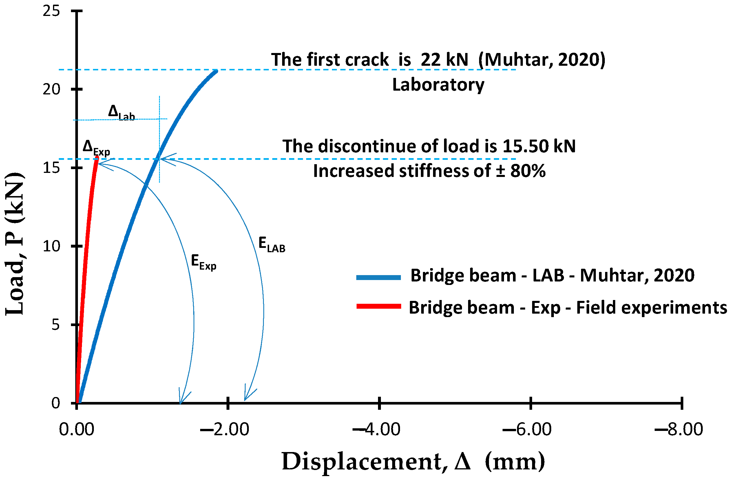
The next step was validating the stiffness of the beam and bridge trusses. The main principle is that the bridge must be in a service condition, with a Serviceability Limit State (SLS) load. The elements of the bridge structure should not be subjected to cracks, deflection, or vibrations causing user discomfort. The allowable deflections are those that are elastic deflection and do not cause the crack. Stiffness is the main parameter of structural resistance. Therefore, the stiffness of the field test results needs to be validated by the stiffness of the laboratory test results. Load–displacement relationship diagrams of the experimental results, laboratory results, and FEM analysis results are combined into one graph. The maximum test load of the bridge becomes the stiffness control limit, which is 15.50 kN. Based on the displacement of the laboratory test results, and the displacement of the field experiments results of the bamboo reinforced concrete frame precast bridge at a stop load of 15.50 kN, the displacement ratio of the laboratory test results to the displacement of the field experiment results (ΔExp/ΔLAB) = 2.6 for the bridge frame and 4.07 for the bridge beam. Figure 35 and Figure 36 shows that the stiffness of the precast bridge beam and precast bridge frame increases ± 80% for the beam stiffness and increases ± 60% for the frame stiffness if it is used as an integral part of other bridge elements.
5. Conclusions
Based on the results of the laboratory tests and field experiments, it appears that the bridge displacement is quite small and comfortable for the user. The maximum beam displacement occurs when the rear wheel is at the center of the span at the 150 cm coordinates and the front wheel is at the 415.5 cm coordinates (the front wheel is outside the bridge). While, the maximum displacement of the frame occurs when the rear wheel is at the 100 cm coordinates and the front wheel is at the 365.5 cm coordinates (the front wheel is outside the bridge).
The minimum beam deformation occurs when the car axle is right on the neutral line of the beam; this shows that the coupling moment or torque due to the load is a factor that greatly affects the size of the beam deformation. Gravity load right on the neutral line can reduce deformation and increase the deflection of the beam and bridge frame, and the size of the torque moment can affect the size of the deformation.
There is a difference in the maximum deformation occurrence between the beam and the bridge frame, namely, the maximum beam deformation occurs when the load is outside the beam coordinates, while the maximum frame deformation occurs when the load is in the middle of the bridge span and outside the frame coordinates.
Precast bamboo reinforced concrete frame bridges have sufficiently good integrity; that is, they can distribute loads with deflection and deformation that do not exceed their permits. The maximum displacement of 0.25 mm meets the requirements based on the AASTHO and RSNI T-12-2004 standards, which is not more than Δmax = L/800 = 3.75 mm. The maximum deformation occurs in the bridge beam of 0.20 mm, and the bridge frame of 0.13 mm meets the requirements based on the AASTHO and RSNI T-12-2004 standards, which is not more than δmax = L/800 = 3.75 mm.
At the stop load of P = 15.5 kN, the stiffness of the bridge beam increased ±80% during the bridge test when compared with the beam stiffness of the laboratory results. Likewise, the stiffness of the bridge frame increased ±60% during the bridge test when compared to the frame stiffness of the laboratory results.
Funding
Funding for this research was fully funded by Community Service Program, the Directorate of Research and Community Service, the Directorate General of Research and Technology Strengthening and Development of the Ministry of Education and Culture of the Republic of Indonesia or DRPM of the Republic of Indonesia, and the results of this research have been applied in Sukogidri Village, Ledokombo District, Jember Regency, Indonesia, as the 2020 PPM Program. PPM activities can be seen at the following link: https://youtu.be/jq1YCEpBDfE.
Acknowledgments
My gratitude goes to the DPRM of the Republic of Indonesia and LPPM of the University of Muhammadiyah Jember, Indonesia, as funders for APC and the implementation of this research.
Conflicts of Interest
The author declares no conflict of interest.
References
- Ghavami, K. Bamboo as reinforcement in structural concrete elements. Cem. Concr. Compos. 2005, 27, 637–649. [Google Scholar] [CrossRef]
- Wikipedia. Bambu petung. 2016. Available online: https://id.wikipedia.org/wiki/Bambu_betung (accessed on 29 August 2020).
- Rahman, M.M.; Rashid, M.H.; Hossain, M.A.; Hasan, M.T.; Hasan, M.K. Performance evaluation of bamboo reinforced concrete beam. Int. J. Eng. Technol. IJET-IJENS 2011, 11, 113–118. [Google Scholar]
- Sahabat Bambu. Available online: https://sahabatbambu.com/ (accessed on 28 August 2020).
- Arsad, E. Teknologi pengolahan dan manfaat bambu. J. Ris. Ind. Has. Hutan 2015, 7, 45–52. [Google Scholar] [CrossRef]
- Umniati, S.B. Analisa Sambungan Balok Kolom Beton Bertulangan Bambu Pada Beban Gempa. Ph.D. Thesis, Universitas Brawijaya, Jawa Timur, Indonesia, 2014. Disertasi, Program Doktor Teknik Sipil. [Google Scholar]
- Muhtar; Dewi, S.M.; Wisnumurti; Munawir, A. The Stiffness and Cracked Pattern of Bamboo Reinforced Concrete Beams Using a Hose Clamp. Int. J. Civ. Eng. Technol. 2018, 9, 273–284. [Google Scholar]
- Muhtar; Dewi, S.M.; Wisnumurti; Munawir, A. Enhancing bamboo reinforcement using a hose-clamp to increase bond- stress and slip resistance. J. Build. Eng. 2019, 26, 100896. [Google Scholar] [CrossRef]
- Stebbings, E.P. Preservation of bamboos from the attacks of bamboo beetle or ‘shot-borers’. Agric. Bull. Straits Fed. Malay States 1904, 3, 15–17. [Google Scholar]
- Xu, Q.; Harries, K.; Li, X.; Liu, Q.; Gottron, J. Mechanical properties of structural bamboo following immersion in water. Eng. Struct. 2014, 81, 230–239. [Google Scholar] [CrossRef]
- Li, M.; Zhou, S.; Guo, X. Effects of alkali-treated bamboo fibers on the morphology and mechanical properties of oil well cement. Constr. Build. Mater. 2017, 150, 619–625. [Google Scholar] [CrossRef]
- Thwe, M.M. Durability of bamboo-glass fiber reinforced polymer matrix hybrid composites. Compos. Sci. Technol. 2003, 63, 375–387. [Google Scholar] [CrossRef]
- Agarwal, A.; Nanda, B.; Maity, D. Experimental investigation on chemically treated bamboo reinforced concrete beams and columns. Constr. Build. Mater. 2014, 71, 610–617. [Google Scholar] [CrossRef]
- Lima, H.C.; Willrich, F.L.; Barbosa, N.P.; Rosa, M.A.; Cunha, B.S. Durability analysis of bamboo as concrete reinforcement. Mater. Struct. Mater. Constr. 2008, 41, 981–989. [Google Scholar] [CrossRef]
- Javadian, A.; Wielopolski, M.; Smith, I.F.C.; Hebel, D.E. Bond-behavior study of newly developed bamboo-composite reinforcement in concrete. Constr. Build. Mater. 2016, 122, 110–117. [Google Scholar] [CrossRef]
- Sakaray, H.; Togati, N.V.V.K.; Reddy, I.V.R. Investigation on properties of bamboo as reinforcing material in concrete. Int. J. Eng. Res. Appl. 2012, 2, 77–83. [Google Scholar]
- Anurag, N.; Arehant, S.B.; Abhishek, J.; Apoorv, K.; Hirdesh, T. Replacement of Steel by Bamboo Reinforcement. IOSR J. Mech. Civ. Eng. 2013, 8, 50–61. [Google Scholar]
- Kaware, A.; Awari, U.R.; Wakchaure, M.R. Review of Bamboo as Reinforcement Material in Concrete Structure. Int. J. Innov. Res. Sci. Eng. Technol. 2013, 2, 2461–2464. [Google Scholar]
- Khan, I.K. Performance of Bamboo Reinforced Concrete Beam. Int. J. Sci. Environ. Technol. 2014, 3, 836–840. [Google Scholar]
- Sethia, A.; Baradiya, V. Experimental Investigation on Behavior of Bamboo Reinforced Concrete Member. Int. J. Res. Eng. Technol. 2014, 3, 344–348. [Google Scholar]
- Terai, M.; Minami, K. Fracture behavior and mechanical properties of bamboo reinforced concrete members. Procedia Eng. 2011, 10, 2967–2972. [Google Scholar] [CrossRef] [Green Version]
- Muhtar. Cracked Pattern of Bamboo Reinforced Concrete Beams Using Double Reinforcement with the Strengthening on Tensile Reinforcement. Int. J. Eng. Res. Technol. 2020, 13, 608–612. [Google Scholar]
- Muhtar. Experimental data from strengthening bamboo reinforcement using adhesives and hose-clamps. Data Brief 2019, 27, 104827. [Google Scholar] [CrossRef]
- Muhtar; Gunasti, A.; Dewi, I.C.; Dasuki, M.; Ariyani, S.; Mahmudi, I.; Abadi, T.; Rahman, M.; Hidayatullah, S.; Nilogiri, A.; et al. The Prediction of Stiffness of Bamboo-Reinforced Concrete Beams Using Experiment Data and Artificial Neural Networks (ANNs). Crystals 2020, 10, 757. [Google Scholar] [CrossRef]
- Nindyawati; Dewi, S.M.; Soehardjono, A. The Comparison Between Pull-Out Test And Beam Bending Test To The Bond Strength Of Bamboo Reinforcement In Light Weight Concrete. Int. J. Eng. Res. Appl. 2013, 3, 1497–1500. [Google Scholar]
- Muhtar; Dewi, S.M.; Wisnumurti; Munawir, A. Bond-Slip Improvement of Bamboo Reinforcement in the Concrete Beam Using Hose Clamps. In Proceedings of the 2nd International Multidisciplinary Conference, Jakarta, Indonesia, 15 November 2016. [Google Scholar]
- Muhtar; Dewi, S.M.; Munawir, A. The Flexural Behavior Model of Bamboo Reinforced Concrete Beams Using a Hose Clamp. In Proceedings of the Materials Science, Engineering, and Chemistry, Bali, Indonesia, 15–17 June 2020. [Google Scholar]
- Karthik, S.; Rao, P.R.M.; Awoyera, P.O. Strength properties of bamboo and steel reinforced concrete containing manufactured sand and mineral admixtures. J. King Saud Univ. Eng. Sci. 2017, 29, 4. [Google Scholar] [CrossRef]
- Dewi, S.M.; Nuralinah, D. Recent Research on Bamboo Reinforced Concrete. In Proceedings of the MATEC Web of Conferences, Bangka Island, Indonesia, 9–10 November 2016; EDP Sciences: Les Ulis, France, 9 March 2017. [Google Scholar]
- Bhonde, D.; Nagarnaik, P.B.; Parbat, D.K.; Waghe, U.P. Experimental Analysis of Bending Stresses in Bamboo Reinforced Concrete Beam. In Proceedings of the 3rd International Conference on Recent Trends in Engineering & Technology (ICRTET’2014), Nagpur, India, 13 March 2014. [Google Scholar]
- Dey, A.; Chetia, N. Experimental study of Bamboo Reinforced Concrete beams having various frictional properties. Mater. Today Proc. 2016, 5, 436–444. [Google Scholar] [CrossRef]
- Leelatanon, S.; Srivaro, S.; Matan, N. Compressive strength and ductility of short concrete columns reinforced by bamboo. Songklanakarin J. Sci. Technol. 2010, 32, 419–424. [Google Scholar]
- Rameshwar, S.; Kale, A.; Rashmirana, P. Suitability of Bamboo as Reinforcement in Column, International. J. Recent Innov. Trends Comput. Commun. 2016, 4, 270–272. [Google Scholar]
- Tripura, D.D.; Singh, K.D. Mechanical behavior of rammed earth column: A comparison between unreinforced, steel and bamboo reinforced columns. Mater. Construcción 2018, 68, 1–19. [Google Scholar]
- Puri, V.; Chakrabortty, P.; Anand, S.; Majumdar, S. Bamboo reinforced prefabricated wall panels for low-cost housing. J. Build. Eng. 2017, 9, 52–59. [Google Scholar] [CrossRef]
- Daud, N.M.; Nor, N.M.; Yusof, M.A.; Yahya, M.A.; Munikanan, V. Axial and Flexural Load Test on Untreated Bamboocrete Multi-Purpose Panel. Int. J. Integr. Eng. 2018, 10, 28–31. [Google Scholar]
- Maruthupandian, G.; Saravanan, R.; Kumar, S.S.; Sivakumar, B.G. A Study on Bamboo Reinforced Concrete Slabs. J. Chem. Pharm. Sci. A 2016, 9, 978–980. [Google Scholar]
- Muhtar; Gunasti, A.; Manggala, A.S.; Nusant, A.F.P.; Hanafi; Nilogiri, A. Effect of Reinforcement Details on Precast Bridge Frames of Bamboo Reinforced Concrete to Load Capacity and Crack Patterns. Int. J. Eng. Res. Technol. 2020, 13, 631–636. [Google Scholar]
- Dewi, S.M.; Wonlele, T. Roof Frame from Bamboo Concrete Composite. J. Mater. Sci. Eng. 2011, 1, 113–116. [Google Scholar]
- ASTM D 143-94 Standart. Standard Test Methods for Small Clear Specimens of Timber. 2000. Available online: http://file.yizimg.com/175706/2011090722382624.pdf (accessed on 29 August 2020).
- Hosta, A.; Fahmi, A.; Farid, M. Mechanical and thermal properties of Indonesian ori bamboo and petung bamboo: Effects of heat treatment. In Proceedings of the National Seminar on Materials and Metallurgy (SENAMM V), Surabaya, Indonesia, 5–6 September 2012; pp. 238–243. [Google Scholar]
- Chinese Standard Agency. Testing Methods for Physical and Mechanical Properties of Bamboo Used in Building; China Architecture & Building Press: Beijing, China, 2007; JG.T199-2007. [Google Scholar]
- Schmidt, G.; Stute, T.; Lenz, M.T.; Melcher, E.; Ressel, J.B. Industrial Crops & Products Fungal deterioration of a novel scrimber composite made from industrially heat-treated African highland bamboo. Ind. Crop. Prod. 2020, 147, 112225. [Google Scholar]
- Fang, H.; Wu, Q.; Hu, Y.; Wang, Y.; Yan, X. Effects of thermal treatment on durability of short bamboo-fibers and its reinforced composites. Fibers Polym. 2012, 14, 436–440. [Google Scholar] [CrossRef]
- PT SIKA Indonesia. Sikadur®-752. 02, 2–3. 2016. Available online: https://www.scribd.com/document/374071630/Sikadur-752 (accessed on 29 August 2020).
- Sattar, M.A. Traditional Bambu Housing in Asia: Present Status and Future Prospects, Bambu, People, and the Environment. In Proceedings of the Vth International Bambu Workshop and the IVth International Bambu Congress 3, Ubud, Indonesia, 19–22 June 1995. [Google Scholar]
- Xiao, Y.; Inoue, M.; Paudel, S.K. Modern Bamboo Structures. In Proceedings of the First International Conference on Modern Bamboo Structures (ICBS-2007), Changsha, China, 28–30 October 2007. [Google Scholar]
- AASTHO Standart. Guide Specification for Seismic Isolation Design; American Association of State Highway and Transportation Officials (AASHTO): Washington, DC, USA, 2010. [Google Scholar]
- Perencanaan Struktur Beton Untuk Jembatan; RSNI T-12-2004. Available online: https://hmtsunsoed.files.wordpress.com/2011/12/rsni-t-12-2004-perenc-str-jembatan-beton1.pdf (accessed on 29 August 2020).
- Muhtar. Numerical validation data of tensile stress zones and crack zones in bamboo reinforced concrete beams using the Fortran PowerStation 4.0 program. Data Brief 2020, 29, 105332. [Google Scholar] [CrossRef] [PubMed]
- SNI-07-SE-2015, DPU. Persyaratan umum perencanaan jembatan. Pedoman Bahan Konstruksi Bangunan Dan Rekayasa Sipil. 2015. Available online: https://dokumen.tips/documents/07sem2015-pedoman-persyaratan-umum-perencanaan-jembatan.html (accessed on 29 August 2020).
Figure 1.
The relationship of load vs. deflection of the bamboo reinforced concrete (BRC) beam [22].
Figure 1.
The relationship of load vs. deflection of the bamboo reinforced concrete (BRC) beam [22].

Figure 2.
The relationship pattern of load vs. deflection of the bridge frame [38].
Figure 2.
The relationship pattern of load vs. deflection of the bridge frame [38].

Figure 3.
Take bamboo from the soaking.

Figure 4.
Drying bamboo in free air.

Figure 5.
Tidy up the bamboo according to size.

Figure 6.
Give a waterproof coating.

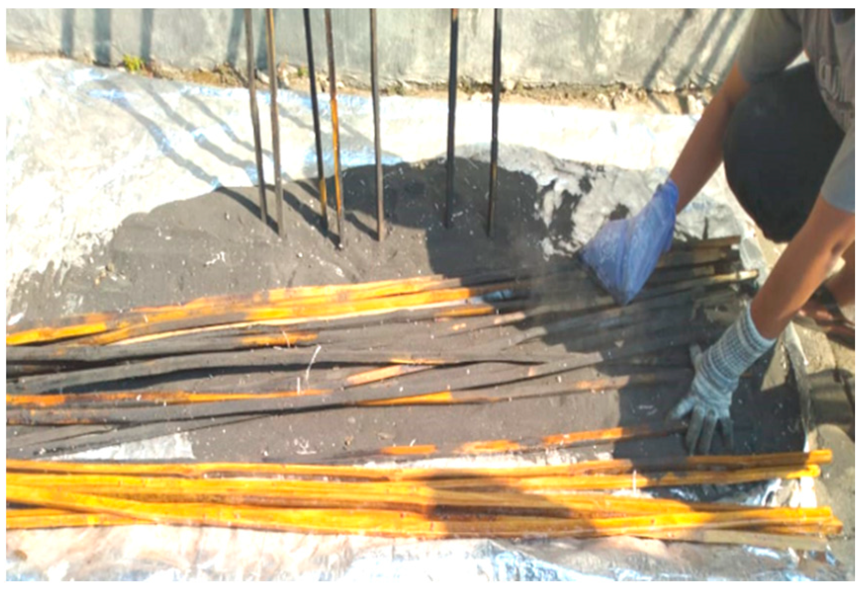
Figure 7.
Sand sprinkling on bamboo reinforcement.

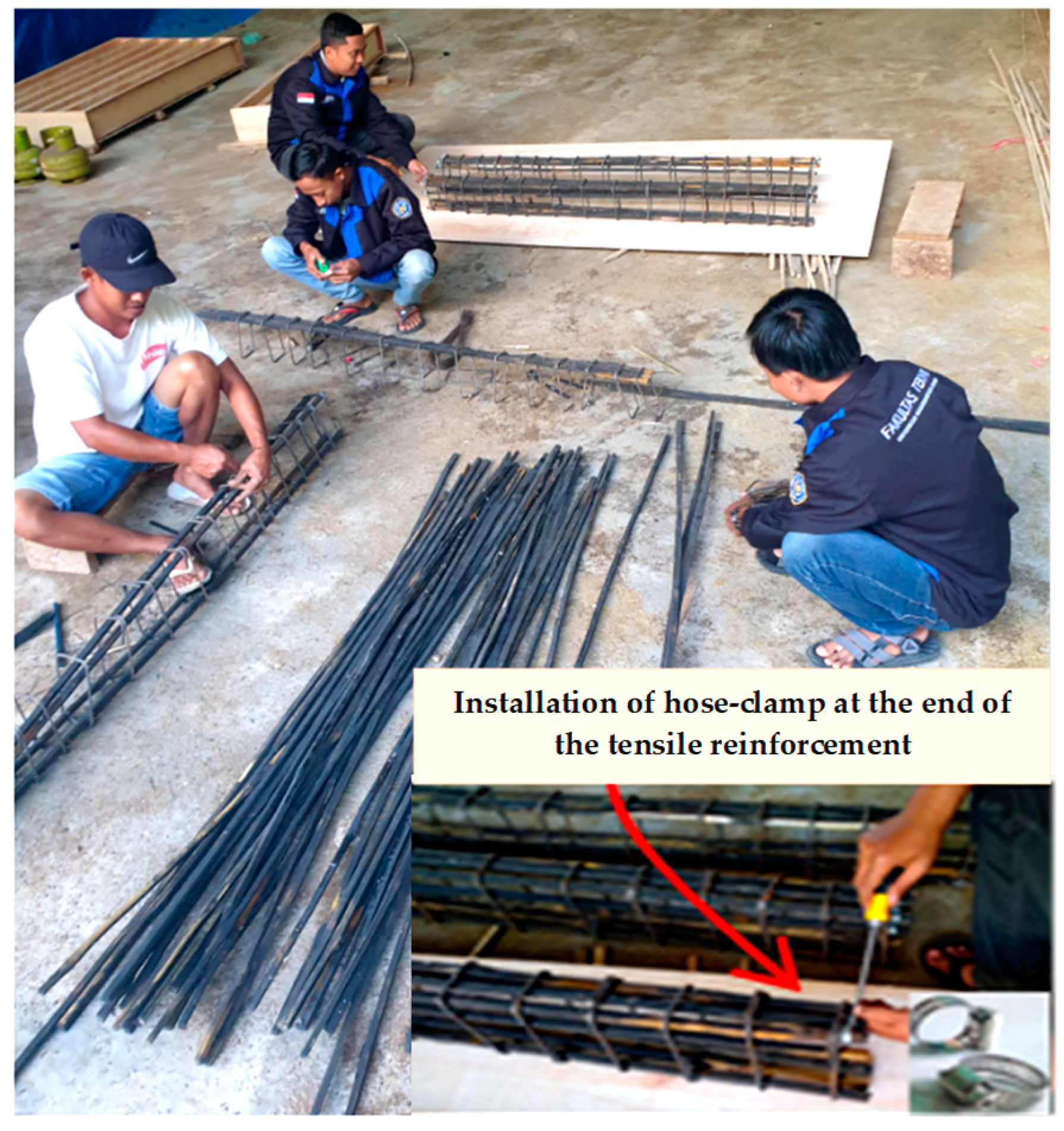
Figure 8.
Stringing the bamboo reinforcement.

Figure 9.
Details of the ring plate and bolt sleeve.

Figure 10.
Models and applications of the precast connections.

Figure 11.
Model of the precast bridge made from bamboo reinforced concrete.

Figure 12.
Details of the precast bridge beam reinforcement [22].
Figure 12.
Details of the precast bridge beam reinforcement [22].

Figure 13.
Details of the precast bridge frame [38].
Figure 13.
Details of the precast bridge frame [38].

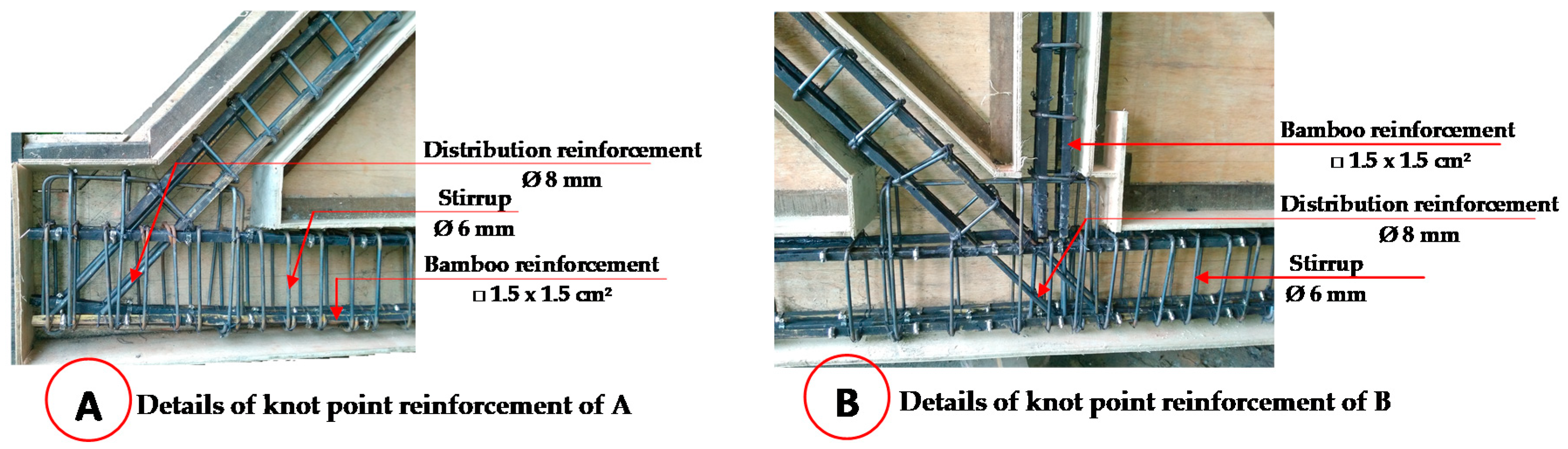
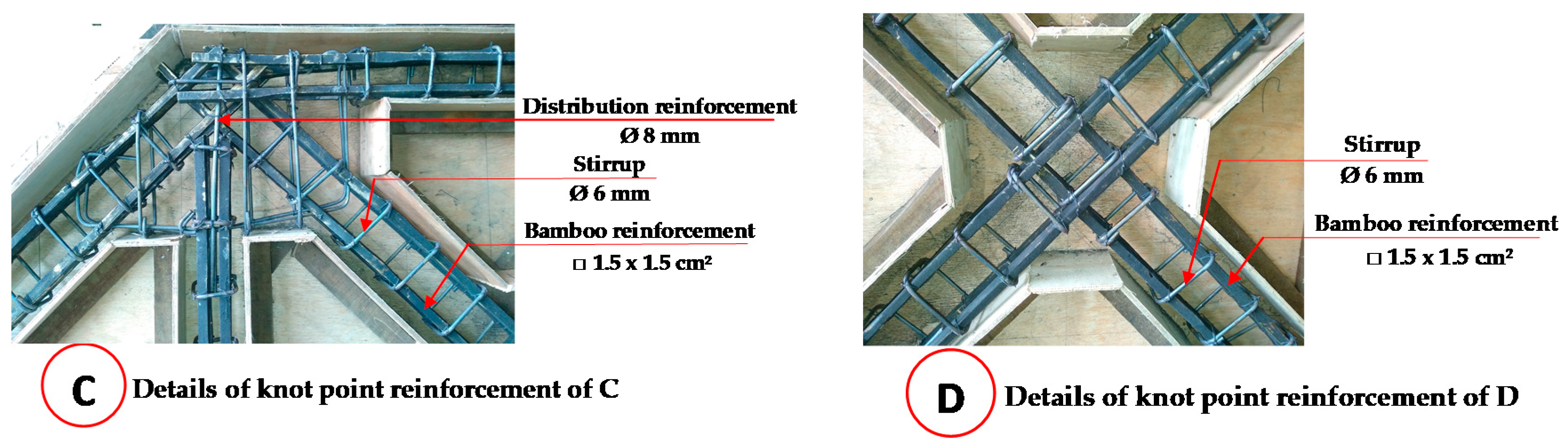
Figure 14.
Details of the knot reinforcement for the bridge frames [38].
Figure 14.
Details of the knot reinforcement for the bridge frames [38].


Figure 16.
Loading stage of the precast bridges with a bamboo reinforced concrete frame.

Figure 17.
The coordinates of the reading points of the displacement and deformation.

Figure 18.
Arrangement of the testing of the bamboo reinforced concrete frame precast bridges.

Figure 19.
The degrees of freedom of the triangular element.

Figure 20.
Displacement of the frame with loads of the Avanza car full of passengers.

Figure 21.
Displacement of the beam with loads of the Avanza car full of passengers.

Figure 22.
Displacement of the frame with loads of the BRIO car full of passengers.

Figure 23.
Displacement of the beam with loads of the BRIO car full of passengers.

Figure 24.
Displacement of the frame with loads of the BRIO car with no passengers.

Figure 25.
Displacement of the beam with loads of the BRIO car with no passengers.

Figure 26.
Deformation of the beam of the precast bridge of bamboo reinforced concrete.

Figure 27.
Deformation of the frame with loads of the Brio car with no passengers.

Figure 28.
Deformation of the frame with loads of the Brio car full of passengers.

Figure 29.
Deformation of the frame with loads of the Avanza car full of passengers.

Figure 30.
Measuring the elastic displacement and deformation.

Figure 31.
Discretization of the bamboo reinforced concrete bridge frames.

Figure 32.
The displacement of Y-direction of the bridge frame.

Figure 33.
The displacement in the X-direction of the bridge frame.

Figure 34.
The relationship of load vs. displacement of the bridge frame.

Figure 35.
The relationship of load vs. displacement of the bridge frame from the laboratory test results, FEM results, and field experiment results.
Figure 35.
The relationship of load vs. displacement of the bridge frame from the laboratory test results, FEM results, and field experiment results.

Figure 36.
The relationship of load vs. displacement of the bridge beam from the laboratory test results and field experiment results.
Figure 36.
The relationship of load vs. displacement of the bridge beam from the laboratory test results and field experiment results.


Table 1.
Mechanical properties of petung bamboo [41].
Table 1.
Mechanical properties of petung bamboo [41].
| Mechanical Properties | |
|---|---|
| Tensile strength (MPa) | 105 ± 8 |
| Modulus of elasticity (GPa) | 26 ± 5 |
| Elongation of fault (%) | 16 ± 1 |
| Flexural strength (MPa) | 153 ± 11 |
| Hardness (VHN) | 5 ± 1 |
| Impact strength (J/mm2) | 0.15 ± 0.7 |
Table 2.
The specifications of Sikadur®-752 [45].
Table 2.
The specifications of Sikadur®-752 [45].
| Components | Properties |
|---|---|
| Color | Yellowish |
| Density | Approx. 1.08 kg/L |
| Mixing Ratio, by weight/volume | 2:1 |
| Pot life at +30 °C | 35 min |
| Compressive strength | 62 N/mm2 at 7 days (ASTM D-695) 64 N/mm2 at 28 days |
| Tensile strength | 40 N/mm2 at 28 days (ASTM D-790) |
| Tensile adhesion strength | 2 N/mm2 (Concrete failure, over mechanically prepared concrete surface) |
| Coefficient of thermal expansion | −20 °C to +40 °C, 89 × 10−6 per °C |
| Modulus of elasticity | 1060 N/mm2 |
Table 3.
The mix composition of the concrete.
| The Concrete Mix Design | Cement (PPC) | Fine Aggregate | Coarse Aggregate | Water |
|---|---|---|---|---|
| Kg/m3 | ||||
| Material per m3 | 381 | 185 | 689 | 1077 |
| Mix composition | 1 | 1.81 | 2.82 | 0.52 |
Table 4.
Details of the bridge frame reinforcement [38].
Table 4.
Details of the bridge frame reinforcement [38].
| Model | I (Shown in Figure 14) | II (Shown in Figure 14) | III (Shown in Figure 14) |
|---|---|---|---|
| Rigid portal model or “frame model” |  |  |  |
Table 5.
Specifications and weight of the minibus car.
| Type of Car | Length | Height | Width | Wheelbase | Empty Weight or One Driver | Passenger Capacity | Weight with Full Passenger |
|---|---|---|---|---|---|---|---|
| mm | mm | mm | mm | kg | Persons | kg | |
| Brio | 3800 | 1485 | 1680 | 2655 | 930–965 | 5 | 1280 |
| Avanza | 4190 | 1695 | 1660 | 2655 | 1045–1095 | 7 | 1550 |
Table 6.
Geometry and specifications of the precast bridges with a bamboo reinforced concrete frame.
Table 6.
Geometry and specifications of the precast bridges with a bamboo reinforced concrete frame.
| Bridge span: | 3 m |
| Foundation: | River stone |
| Bridge support: | Concrete slab = assumption of hinge support; Concrete slabs and rubber pads = assumption of the roller support |
| Beam: |
|
| Connection type: | Precast system connection, using bolts and sleeves of 19 mm diameter |
| Frame model: | Rigid portal model or “frame model” |
| Bridge slab: |
|
| Displacement and deformation of permit: | Based on AASHTO [48] and RSNI T-12-2004 standards [49], the maximum displacement of permit is Δmax = L/800 = 3.75 mm |
Table 7.
Data on the test results of the precast bridge with bamboo reinforced concrete frames.
| Bridge Load | Displacement and Deformation | ||||||
|---|---|---|---|---|---|---|---|
| Frame 1 | Frame 2 | Beam 1 | Beam 2 | ||||
| Displacement 1 (mm) | Deformation 2 (mm) | Displacement 1 (mm) | Deformation 2 (mm) | Displacement 1 (mm) | Deformation 2 (mm) | Displacement 1 (mm) | |
| Brio 930 kg | 0.2 | 0.03 | 0.04 | 0.04 | 0.06 | 0.01 | 0.14 |
| Brio + Pn 1280 kg | 0.2 | 0.01 | 0.04 | 0.05 | 0.08 | 0.06 | 0.17 |
| Avanza + Pn 1550 kg | 0.25 | 0.01 | 0.04 | 0.13 | 0.14 | 0.2 | 0.21 |
1 Displacement is the deflection of the direction of gravity on the beam or frame elements due to the distribution of the vehicle loads within the elastic limit. 2 Deformation is a change in shape or a change in the angle of the cross-section of the beam or frame due to the distribution of the vehicle loads within the elastic limit measured as the direction of the horizontal of the cross-section.
Publisher’s Note: MDPI stays neutral with regard to jurisdictional claims in published maps and institutional affiliations. |
© 2020 by the author. Licensee MDPI, Basel, Switzerland. This article is an open access article distributed under the terms and conditions of the Creative Commons Attribution (CC BY) license (http://creativecommons.org/licenses/by/4.0/).
Share and Cite
MDPI and ACS Style
Muhtar. Precast Bridges of Bamboo Reinforced Concrete in Disadvantaged Village Areas in Indonesia. Appl. Sci. 2020, 10, 7158. https://doi.org/10.3390/app10207158
AMA Style
Muhtar. Precast Bridges of Bamboo Reinforced Concrete in Disadvantaged Village Areas in Indonesia. Applied Sciences. 2020; 10(20):7158. https://doi.org/10.3390/app10207158
Chicago/Turabian StyleMuhtar. 2020. "Precast Bridges of Bamboo Reinforced Concrete in Disadvantaged Village Areas in Indonesia" Applied Sciences 10, no. 20: 7158. https://doi.org/10.3390/app10207158
Note that from the first issue of 2016, this journal uses article numbers instead of page numbers. See further details here.