1. Introduction
A lack of information needed to visualize building energy simulation results prevents the efficient use of such results in developing schematic designs in the early design stages. Ozkan et al. [
1] pointed out that the visualization of building energy performance information at the early design stage can facilitate the energy−reduction strategies. Some of software applications including plug-in applications are available in the market to support building energy simulation−based design at the early design stage [
2,
3,
4,
5,
6,
7,
8]. Most of the applications have the difficulty of seamless object mapping for information visualization between a building component and the simulation result. In order to improve information visualization, we investigated a platform for depicting building energy performance, focusing on thermal energy performance in building information modeling (BIM). To develop the platform, we first created a BIM model of Building Energy Simulation Test (BESTEST) Case 600 [
9] to experiment with our method and develop a case study. Second, we created a thermal energy performance indicator (TEPI) parameter to store thermal building energy performance results after conducting object-oriented physical modeling−based building energy performance simulation (OOPM−BEPS). Third, we designed a visibility setting in the BIM authoring tool that uses TEPI values to color−code building components. Finally, we developed the thermal energy performance visualization (TEPV) using the application programming interface (API) programming method. The TEPV enables building components in a BIM model to update TEPI values for simulated time and change the building components’ colors automatically.
The research objectives in developing this platform includes (1) providing the results of thermal energy performance through the TEPI parameter in BIM models, (2) displaying a series of thermal energy performance results as color-coding building components, and (3) enabling stakeholders in the early design stages to use the BIM tool as a common user interface when developing architectural models and thermal energy performance visualizations.
Our study is significant in that we demonstrate a new method for associating the representation of thermal energy performance obtained from an OOPM−BEPS with color-coded building components in BIM. This approach is distinctly different from other building performance representations and other BEPS tools; our information visualization in BIM from OOPM−BEPS provides a new and sophisticated object−based performance visualization and mapping method. Consequently, the developed platform facilitates that architects become better informed based on the intuitive object−oriented building performance simulation results at the early design stage.
The following sections present the details of our research methods, implementation, verification, and results. Also, findings from the interfacing of BIM and OOPM−BEPS for visualization are discussed. In this research, the terms “building information modeling” and “building information models” may both the abbreviated as BIM and used in different contexts.
2. Problems and Challenges
While building energy performance simulation (BEPS) tools have become one of the main means of evaluating building performance in sustainable design, most of the current thermal simulation applications such as DOE−2, EnergyPlus, eQUEST, Green Building Studio (GBS), etc. require a building geometry information retrieval process achieved through computer-aided design tools [
10] that exchange BIM data with thermal modeling [
11]. In addition, BES tools typically generate a large quantity of numbers in tables and charts after thermal simulations are conducted [
12,
13]. Such a process causes interoperability problems and stakeholders involved in the early design stage, such as designers and engineers, may find it difficult to investigate thermal results after completing simulations. Currently, few BEPS tools are supporting integration with BIM; GBS can be utilized during the simulation process with specific BIM authoring tools such as Revit [
12,
14,
15,
16,
17]. Research efforts for visualization of energy simulation results [
18,
19] have explored developing a better comprehension of building energy performance analysis. However, the tools developed still have difficulties providing feedback during the early design process. They only offer many tables and numbers; it is time-consuming to find the distinct relationships between the simulation result and the building component (i.e., which components perform well and which do not), which is information critical to improving building design.
3. Objective and Approach
The objective of this study was to facilitate sustainable design through information visualization of OOPM−BEPS results in the early design stage. To achieve this goal, we developed a platform by integrating BIM and the results from OOPM−BEPS tools (i.e., we integrated the capability of OOPM−BEPS visualization in BIM).
For this integration, our research method is based on the BIM technologies including the API of the BIM tools and OOPM−BEPS using the OOPM method. Even BIM facilitates access to comprehensive building information that accumulate throughout the building’s lifecycle [
20] and allows parametric modeling in the design stage, OOPM supports object-oriented building performance simulation results [
21]. Our research utilizes the advantages of BIM and OOPM−BEPS for visualization—an object-based modeling approach for building and energy modeling and an object-oriented programming method. The object-based modeling approach enables direct access to BIM and simulation results, and the object-oriented computer programming method facilitates a system interface for visualization between BIM and OOPM−BEPS.
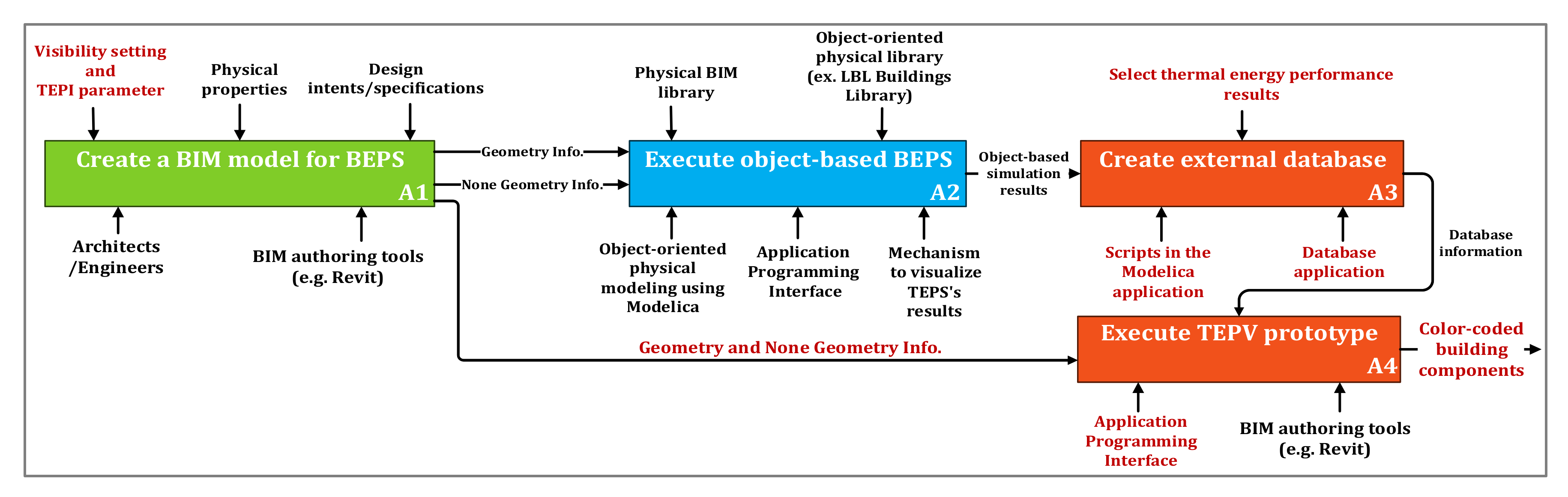
Figure 1 shows the overall process of this research, including all steps and activities (A1, A2, A3, and A4).
The green component (A1) in
Figure 1 represents the process of creating a BIM model, including the information required to create an OOPM−BEPS. The A1 activity consists of the following three major control components: (1) visibility setting and TEPI parameter, (2) physical properties, and (3) design intent and specifications. The stakeholders and specific tool, represented as architects/engineers and BIM authoring tools in the A1 activity, enable a BIM model to be created with particular values for the controls. The output from the A1 activity is a BIM model consisting of geometry and no geometry information.
The blue component in
Figure 1 is the OOPM−BEPS process adopted from [
12,
14,
15,
23,
24]. Previous work integrating BIM and OOPM-based building energy model (BEM) evaluated the use of object-oriented BIM and BEM, enabling more reliable and efficient model translation and guaranteeing efficient maintainability [
12,
14,
15,
16,
23,
24]. The A2 activity represents the object-based BEPS method adopted for thermal energy performance simulations, based on the BIM model. The control components of the A2 activity include the physical BIM library developed from [
14] and object−oriented physical library developed from [
25]. The control components facilitate model translation and BIM-based OOPM−BEM [
12,
14,
23]. The three main control components (i.e., OOPM using Modelica, API, and Mechanism) of the A1 activity enable model translation between BIM and OOPM−based BEM under two control components. Thus, three OOPM−BEM model translated from the BIM model can be used to conduct building energy performance simulations and provide object-oriented thermal simulation results.
The simulation results from the A2 activity are converted as input data for the A3 activity. The main function of A3 is to create an external database to accumulate the object-based thermal simulation results from the A2 activity. Even simulation results consisting of object-based results mapped with specific building components including walls and floors are still composed of a large quantity of numerical simulation results. In order to access specific information among the results, each value needs to be stored in individual containers such as cells in the external database applications (Excel or Access).
The A4 activity represents the TEPV workflow. The activity has geometric information from the A1 activity as the input and database information from the A3 activity as the control component. Based on the input and control component, the specific value is represented as a color-coded building component under the API mechanism and BIM authoring tool.
4. Methodology
Our methodology included the following process:
Designing a set of steps for the TEPV, including creation of the TEPI parameter and visibility setting;
Prototyping a system interface through BIM’s API to implement TEPV; and
Conducting a case study using a benchmark energy performance test model (i.e., BESTEST Case 600) to verify the prototype.
In the following section, we discuss BIM preprocessing to define the steps for the TEPV, prototyping of the TEPV implementation, and verification of the suggested method by applying the prototype to a benchmark model.
4.1. BIM Preprocessing
Before executing the TEPV, the BIM needed to be preprocessed to apply thermal simulation results, as follows. In order to implement the TEPV, we utilized the modeling ability of a specific BIM authoring tool (i.e., Revit 2020 version [
26]).
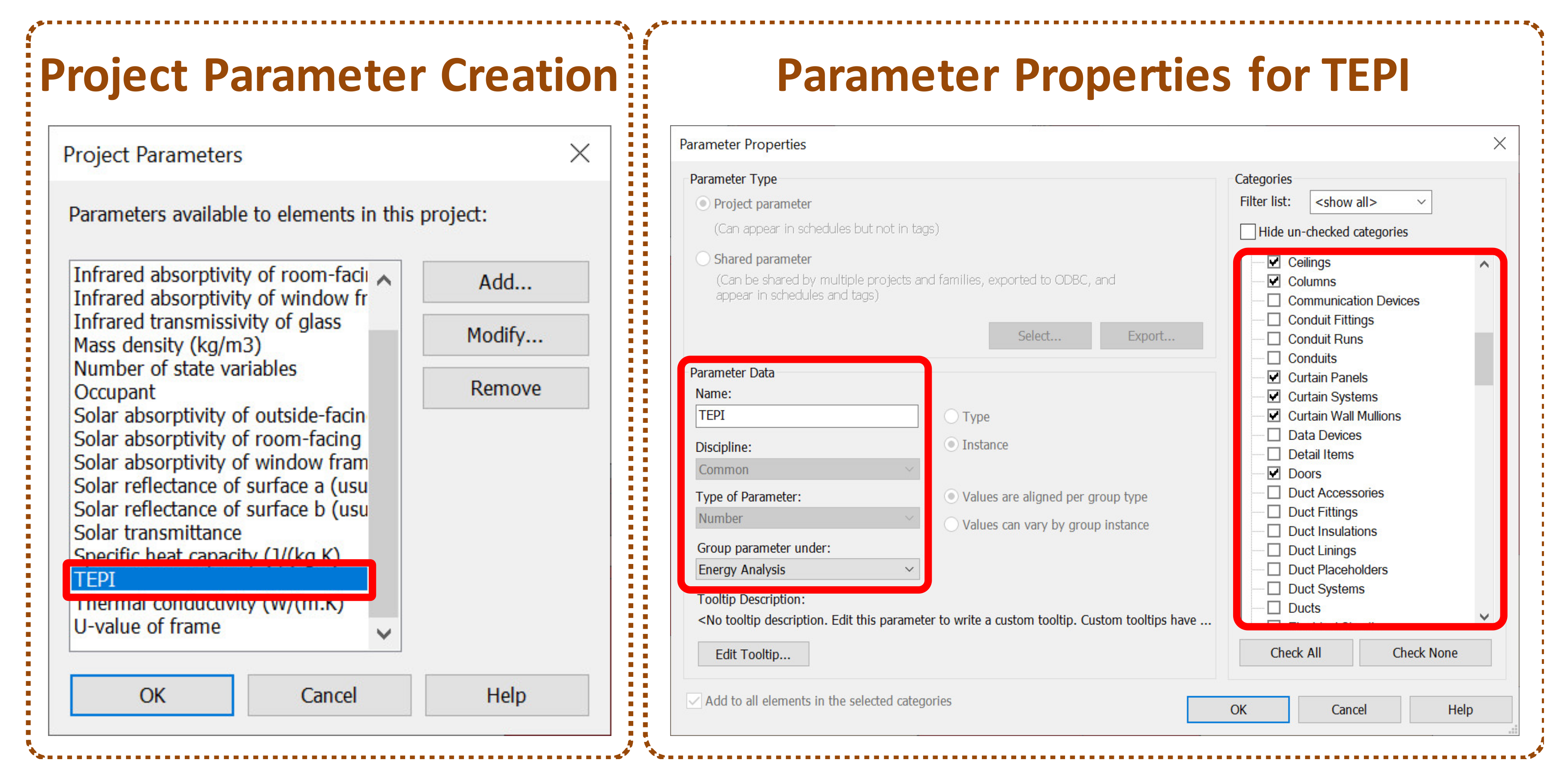
• Creating the TEPI parameter: We created the TEPI parameter to apply the thermal simulation results from the OOPM−BEPS to the building components, due to the absence of a relevant parameter in the BIM model. The parameter was assigned as a project parameter so that all of the building components could include information from the OOPM−BEPS results.
Figure 2 shows how to create a TEPI parameter in Revit and illustrates that the TEPI was defined as a project parameter to apply its values to the building components. Once the TEPI parameter was defined as a project parameter, we assigned the TEPI’s properties to the energy analysis group parameter and applied it to building component categories such as ceilings, columns, curtain panels, curtain systems, curtain wall mullions, doors, walls, etc.
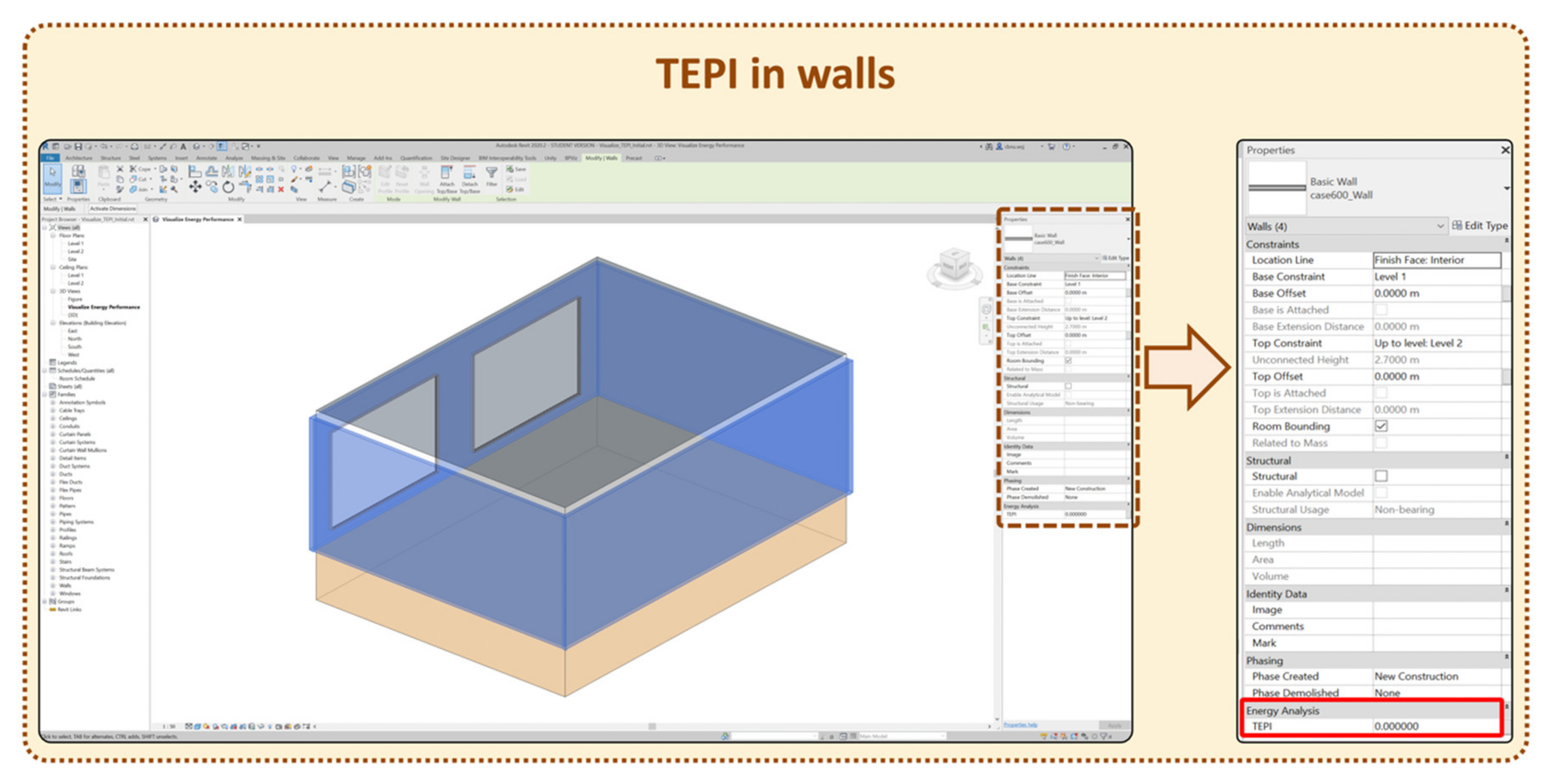
After creating the TEPI parameter and its properties (see
Figure 2), users could confirm the assigned parameter with the selection of building components in the Properties window in Revit (see
Figure 3). We assigned the TEPI parameter to the energy analysis group when in the project parameter creation stage. The Properties window of the building components selected showed the TEPI parameter under the energy analysis group (the red solid−lined box in
Figure 3).
• Visibility setting: Visibility settings were needed to generate the color−coded building objects through the updated values in the TEPI parameter. The visibility settings enabled the building components to be represented by target colors. The settings consisted of a series of ranges, each with a different color (e.g., a range from 0 to 100 could be assigned a light red color, and if the value of the TEPI parameter was within the range, the component containing the value would be visualized as a light red color). As shown in
Figure 4, we created a rating system using the Filters function in the Visibility/Graphic Overrides window in Revit. The rating system had 10 levels with different colors, each divided into 50 numbers, from Rating_2 to Rating_10. The Rating_1 and Rating_10 levels had 100 and 30 numbers, respectively. (i.e., the values for the 10th level were between −400 and −430 Watts).
4.2. Prototyping
We created the TEPV prototype using Autodesk Revit as a BIM authoring tool and its API (in C# programming language) [
27] and utilized Lawrence Berkeley National Laboratory, Berkeley, CA, U.S. (LBNL)’s Modelica Buildings library [
25] for the OOPM−BEPS. We also used Dymola
®, Vélizy-Villacoublay, FRANCE [
28] as the OOPM−BEPS environment. The prototype feeds the information from the OOPM−BEPS tool into the TEPI parameter through an external database. The database was generated after completing the OOPM−BEPS, which provided object−based energy simulation results such as the heat flow rates for each building component. Because the value of the TEPI parameter was updated automatically, the building components were represented by designated color from the visibility settings for the simulation time.
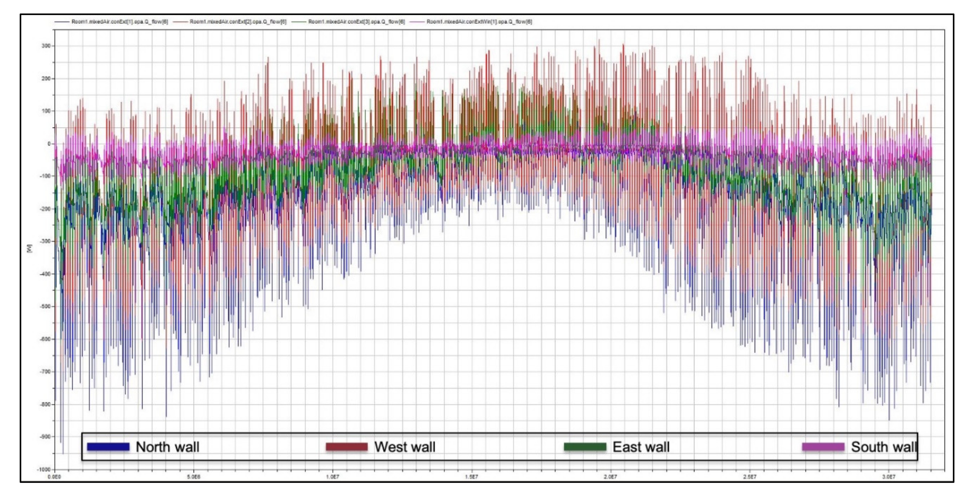
Based on the OOPM−BEPS tool (i.e., Dymola), the object-based thermal simulation results were generated as shown in
Figure 5.
Figure 5 illustrates the heat flow rates simulation results of four walls in a one−room energy simulation model. The results were represented by graphs and the external database stored them as numbers, checking corresponding building energy performance results for building components using the export function in the Dymola tool. We utilized Excel spreadsheets for the external database. The graphs were translated into a comma-separated value (CSV) file in Excel. We created a script file and executed it in Dyamola to automatically retrieve the thermal energy performance simulation values and export them into the CSV file.
The prototype checked the building components and saved the identification (ID) numbers. From the ID numbers, the prototype retrieved the simulation results from the database. The results were stored in the TEPI parameter in a BIM model. Once the building components had their TEPI values, they were represented by colors designated through a previous visibility setting.
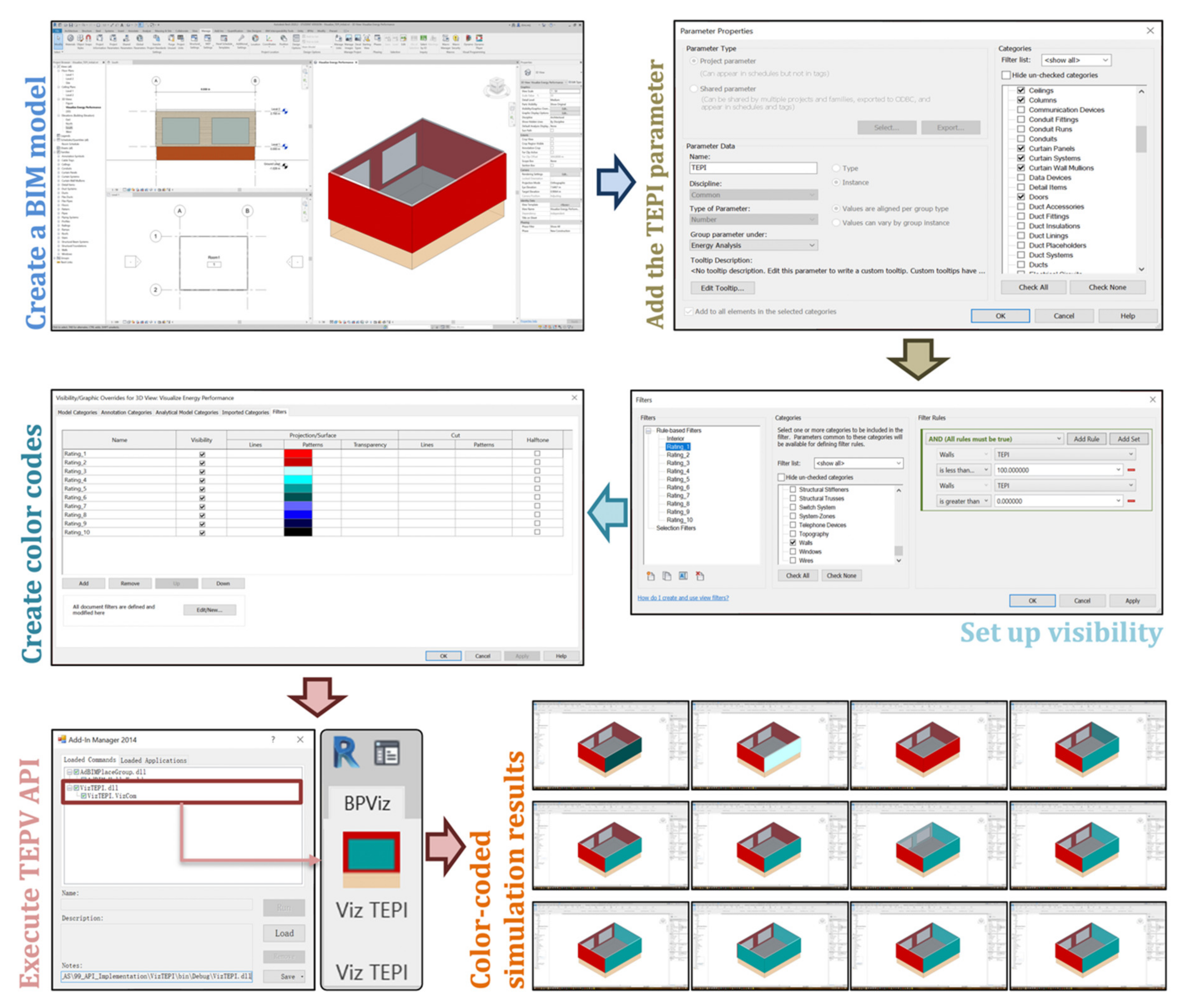
Figure 6 shows the workflow diagram of the TEPV.
The TEPV prototype had six phases: (1) create a BIM model, (2) add the TEPI parameter, (3) set up visibility, (4) create color codes, (5) execute the TEPV API, and (6) collect the color-coded simulation results.
Create a BIM model: We created a sample BIM model to which we applied the TEPV API. The specific information from the BIM model is described below, in the verification section.
Add the TEPI parameter: We applied the TEPI parameter creation process to the BIM model.
Set up visibility: The visibility setup process for applying a specific value range of simulation results was conducted through the BIM model.
Create color codes: Ten colors were assigned to the visibility rating filters created.
Execute the TEPV API: We created the Viz TEPI command for the TEPV API. The TEPV API consisted of the Viz TEPI command (the dark red box in the “Execute TEPV API” process in
Figure 6) and application (the right figure in the “Execute TEPV API” process in
Figure 6)). The Viz TEPI command had the VizTEPI.dll file, allowing for the stored thermal simulation results to be fed into the CSV file within the TEPI parameter in the BIM model. The Viz TEPI command facilitated development of dll files without using an AddIn file that would enable Revit to recognize any APIs of dll files when the process began. Once the dll was verified through several experimental test cases, we created the Viz TEPI application. The Viz TEPI application facilitated execution of the command.
Collect the color-coded simulation results: Once the Viz TEPI application was executed, the building components targeted in the BIM model were represented as designated colors, as shown in
Figure 6.
4.3. Verification
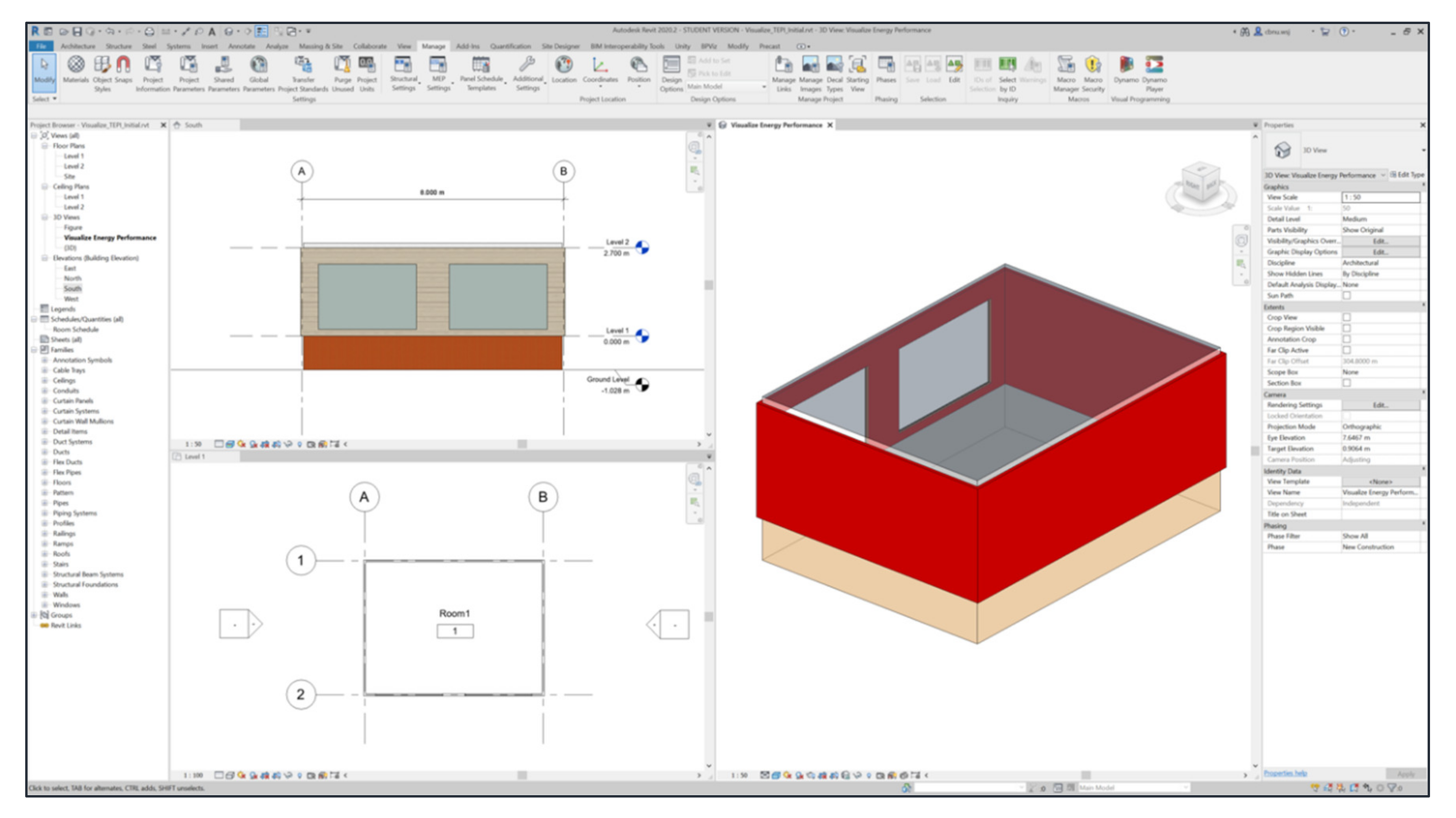
We have conducted a case study for the verification of our TEPV prototype by creating a equivalent BIM model for BESTEST Case 600 (see
Figure 7). The case study visualized the heat flow rate among the thermal simulation results for the wall components. After the BIM model was created, we generate the TEPI parameter into the project parameters (see
Figure 2 and
Figure 3). As shown in
Figure 2, the entire set of wall components provided heat flow rate results through the TEPI parameter. We executed the OOPM−BEPS tool to generate object-based thermal simulation results.
Figure 5 illustrates some of the thermal simulation results and heat flow rate for the wall components for one year. The values from the graphs were translated into an Excel (CSV) file by the Dymola’s export function. Our case study only utilized part of the heat flow rate; the results provided six stages for each wall, and we chose the sixth heat flow rate value for the case study.
The BESTEST Case 600 building model is defined in [
29,
30]. The detailed building description is as follows:
One room consists of a single thermal zone and its dimension is 8.0 m, 6.0 m, and 2.7 m for the length, width, and height, respectively.
The building had two south oriented 6 m2 windows and no doors.
The building envelope’s material properties are shown in
Table 1.
The shade and internal heat gain of the building from occupancy and equipment was nonexistent.
The main floor of the building was above ground level, no attached to the ground.
The location of the building was Denver, CO, USA.
The building was lightweight, and the room temperature control set to 20 °C and 27 °C for heating and cooling, respectively.
The experimental BIM model for the BESTEST 600 case was created using Autodesk Revit 2021 version [
26] as a BIM authoring tool (see
Figure 7), Dymola [
28] as a Modelica development environment, and the LBNL Modelica Buildings library as an OOPM−BEPS solver. The solver tolerance for the thermal energy performance simulation was 10
−6, and the interval of the simulation was 3600 s for the year.
After generating the external database for the heat flow rate information, we executed a TEPV for a one-year thermal simulation. Even the database provided 8760 different time snapshots for each wall, we retrieved only 12 for each wall in the visualization. The TEPV began the thermal performance visualization with the north wall and continued to from the west wall till east wall through south wall sequentially.
Table 2 includes visualization of the TEPI values for one year.
Since we considered the sixth of the total heat flow rate values from the BEPS results,
Table 2 shows all negative values (i.e., the total heat flow rates were positive in summer and negative in winter, as shown in
Figure 5); the negative values indicated that heat flowed from the inside to the outside of the walls. The heat flow rate values were calculated according to how many joules were measured per second (in Watts) and stored in the TEPI parameter in the BIM model. Based on the visibility setting, the range of each rate ware 30, 50, or 100 (see
Figure 4), and assigned the color. If the values in the wall were of same rate, the wall was represented by the same color at different simulation times (e.g., the north wall was represented by a dark red color on the 175th, 200th, 225th, and 250th days because the values for those days represented the same rate in the visibility setting).
Table 2 shows which walls were critical for heat flow on a specific date (e.g., the north, west, south, and east walls were represented by dark blue, light blue, dark red, and light blue, respectively, on the 275th day, where light red was assigned to indicate a low heat flow rate).
5. Conclusions
Our approach demonstrates a new method that supports an improved sustainable design process by providing visualized thermal BEPS for BIM users. The prototype developed is expected to benefit sustainable building energy design by visualizing thermal performances of building components. Moreover, the TEPV prototype shows BIM capability, serving as a common user interface for designers to explicitly check BEPS results by visualizing building components for the building design process. In addition, our method facilitates architects to identify the specific building objects most critical to thermal efficiency by investigating color-coding building components at the early design stages. Consequently, our prototype facilitates architects becoming better informed, improving their sustainable designs in the early design stages, where the impact of design decisions is critical to building thermal energy performance. Current prototype only represents the loads simulation results into opaque building components such as walls, floors, and roofs, while the developed framework [
12] of OOPM−BEPS can represent building component−based simulation results. We will demonstrate thermal performance visualization of the non−opaque building component in the future research. Also, in near future, we will investigate additional OOPM−BEPS results such as indoor air temperature, solar radiation, infiltration, and energy performance of the self-shading building envelope in our prototype.
Author Contributions
All authors contributed to this research work, discussed the results and implications, and involved in the manuscript development at all stages. W.J. implemented the system interface, developed the research idea, and led the development of the research paper. W.Y. provided precious ideas on the establishment of the research. C.J.L. discussed the main idea to develop the research work and revied the manuscript as well. All authors have read and agreed to the published version of the manuscript.
Funding
This research was supported by the Basic Science Research Program through the National Research Foundation of Korea (NRF) funded by the Ministry of Education (2020R1I1A3052594).
Acknowledgments
This work was supported by the National Research Foundation of Korea (NRF) grant funded by the Korea government (MSIT) (No. 2019R1H1A1080281), and this material is based upon work partially supported by the National Science Foundation under Grant No. 0967446.
Conflicts of Interest
The authors declare no conflict of interest.
References
- Ozkan, A.; Kesik, T.; Yilmaz, A.Z.; O’Brien, W. Development and visualization of time-based building energy performance metrics. Build. Res. Inf. 2019, 47, 493–517. [Google Scholar] [CrossRef]
- Tian, M.; Zhang, L.; Su, Y.; Xuan, Q.; Li, G.; Lv, H. An evaluation study of miniature dielectric crossed compound parabolic concentrator (dCCPC) panel as skylights in building energy simulation. Sol. Energy 2019, 179, 264–278. [Google Scholar] [CrossRef]
- Pak, M.; Smith, A.; Gill, G.N. Ladybug: A Parametric Environmental Plugin for Grasshopper to Help Designers Create an Environmentally-conscious Design. In Proceedings of the BS2013: 13th Conference of the International Building Performance Simulation Association, Chambery, France, 26–28 August 2013. [Google Scholar]
- Elbeltagi, E.; Wefki, H.; Abdrabou, S.; Dawood, M.; Ramzy, A. Visualized strategy for predicting buildings energy consumption during early design stage using parametric analysis. J. Build. Eng. 2017, 13, 127–136. [Google Scholar] [CrossRef]
- Oh, T.-K.; Lee, D.; Park, M.; Cha, G.; Park, S. Three-Dimensional Visualization Solution to Building-Energy Diagnosis for Energy Feedback. Energies 2018, 11, 1736. [Google Scholar] [CrossRef] [Green Version]
- Ruiz, L.G.B.; Pegalajar, M.C.; Molina-Solana, M.; Guo, Y.-K. A case study on understanding energy consumption through prediction and visualization (VIMOEN). J. Build. Eng. 2020, 30, 101315. [Google Scholar] [CrossRef]
- Nugraha Bahar, Y.; Landrieu, J.; Pére, C.; Nicolle, C. CAD data workflow toward the thermal simulation and visualization in virtual reality. Int. J. Interact. Des. Manuf. 2014, 8, 283–292. [Google Scholar] [CrossRef]
- Natephra, W.; Motamedi, A.; Yabuki, N.; Fukuda, T.; Michikawa, T. Building envelope thermal performance analysis using BIM-based 4D thermal information visualization. In Proceedings of the 16th International Conference on Computing in Civil and Building Engineering (ICCCBE2016), Osaka, Japan, 6–8 July 2016; pp. 1539–1546. [Google Scholar]
- ANSI/ASHRAE Standard. Standard 140-2007 Standard Method of Test for the Evaluation of Building Energy Analysis Computer Programs; American Society of Heating, Refrigerating and Air- Conditioning Engineers: Atlanta, GA, USA, 2010. [Google Scholar]
- Bazjanac, V. Acquisition of Building Geometry in the Simulation of Energy Performance; Lawrence Berkeley National Laboratory: Rio de Janeiro, Brazil, 2001. [Google Scholar]
- Mitchell, J.; Wong, J.; Plume, J. Design Collaboration Using IFC. In Computer Aided Architectural Design Futures; Springer: Sydney, Australia, 2007; pp. 317–329. [Google Scholar]
- Jeong, W.; Kim, J.B.; Clayton, M.J.; Haberl, J.S.; Yan, W. A framework to integrate object-oriented physical modelling with building information modelling for building thermal simulation. J. Build. Perform. Simul. 2015, 9, 50–69. [Google Scholar] [CrossRef]
- Haberl, J.S. SIMBUILD Survey: Academic Use of Simulation Software. In Proceedings of the SIMBUILD 2008, Berkeley, CA, USA, 30 July–1 August 2008. [Google Scholar]
- Kim, J.B.; Jeong, W.; Clayton, M.J.; Haberl, J.S.; Yan, W. Developing a physical BIM library for building thermal energy simulation. Autom. Constr. 2015, 50, 16–28. [Google Scholar] [CrossRef]
- Jeong, W.; Son, J. An Algorithm to Translate Building Topology in Building Information Modeling into Object-Oriented Physical Modeling-Based Building Energy Modeling. Energies 2016, 9, 50. [Google Scholar] [CrossRef] [Green Version]
- Jeong, W.; Kim, K.H. A Performance Evaluation of the BIM-Based Object-Oriented Physical Modeling Technique for Building Thermal Simulations: A Comparative Case Study. Sustainability 2016, 8, 648. [Google Scholar] [CrossRef] [Green Version]
- Jeong, W.; Kim, J.B.; Clayton, M.J.; Haberl, J.S.; Yan, W. Visualization of Building Energy Performance in Building Information Models. In Proceedings of the ACADIA 13: Adaptive Architecture—33rd Annual Conference of the Association for Computer Aided Design in Architecture, Cambridge, ON, Canada, 24–26 October 2013; 2013; pp. 87–92. [Google Scholar]
- Sreshthaputra, A.; Haberl, J.; Andrews, M.J. Improving building design and operation of a Thai Buddhist temple. Energy Build. 2004, 36, 481–494. [Google Scholar] [CrossRef]
- Haberl, J.; Akleman, E. Demonstration of the Use of Multimedia Electronic Information Enhancements for a Chapter Handbook CD-ROM: 3D Modeling and Animation. (Report). ASHRAE Trans. 2010, 116, 316–322. [Google Scholar]
- Eastman, C.; Teicholz, P.; Sacks, R.; Liston, K. BIM Handbook: A Guide to Building Information Modeling for Owners, Managers, Designers, Engineers, and Contractors; Wiley and Sons: Hoboken, NJ, USA, 2008. [Google Scholar]
- Fritzson, P.A. Principles of Object-Oriented Modeling and Simulation with MODELICA 2.1; Wiley-IEEE Press: Hoboken, NJ, USA, 2004. [Google Scholar]
- NIST. FIPS Publication 183: Integration Definition of Function Modeling (IDEF0); NIST Publications: Gaithersburg, MD, USA, 1993. [Google Scholar]
- Yan, W.; Clayton, M.; Haberl, J.; Jeong, W.; Kim, J.; Kota, S.; Bermudez Alcocer, J.; Dixit, M. Interfacing BIM with Building Thermal and Daylighting Modeling. In Proceedings of the BS2013: 13th Conference of the International Building Performance Simulation Association, Chambery, France, 26–28 August 2013. [Google Scholar]
- Jeong, W.; Kim, J.B.; Clayton, M.J.; Haberl, J.S.; Yan, W. Translating Building Information Modeling to Building Energy Modeling Using Model View Definition. Sci. World J. 2014, 2014, 1–21. [Google Scholar] [CrossRef] [PubMed] [Green Version]
- Wetter, M.; Zuo, W.; Nouidui, T.S.; Pang, X. Modelica Buildings library. J. Build. Perform. Simul. 2014, 7, 253–270. [Google Scholar] [CrossRef]
- Autodesk Inc. Revit|BIM Software|Autodesk Official Store. Available online: https://www.autodesk.com/products/revit/overview (accessed on 6 May 2020).
- Revit Platform Technologies|Autodesk Developer Network. Available online: https://www.autodesk.com/developer-network/platform-technologies/revit (accessed on 9 May 2020).
- Dassault Systèmes Multi-Engineering Modeling and Simulation—Dymola—CATIA—Dassault Systèmes. Available online: http://www.3ds.com/products-services/catia/portfolio/dymola/overview/ (accessed on 24 August 2013).
- Judkoff, R.; Neymark, J. International Energy Agency Building Energy Simulation Test. (bestest) and Diagnostic Method; National Renewable Energy Lab: Golden, CO, USA, 1995. [Google Scholar]
- Pedersen, C.O.; Liesen, R.J.; Strand, R.K.; Fisher, D.E. A Toolkit for Building Load Calculations; American Society of Heating, Refrigerating and Air-Conditioning Engineers, Inc.: Atlanta, GA, USA, 2001. [Google Scholar]
© 2020 by the authors. Licensee MDPI, Basel, Switzerland. This article is an open access article distributed under the terms and conditions of the Creative Commons Attribution (CC BY) license (http://creativecommons.org/licenses/by/4.0/).


