1. Introduction
Artificial lighting from luminaire has been an essential part of modern society due to the expansion of urban areas with high-rise building that block the natural lighting, working space that less likely to receive daylight, and night-time activity that required lighting. Thus, the quality of lighting has become directly correlated to the quality of life. This result in large amounts of power consumption in residential, commercial, and industrial sectors delicate to lighting systems. In the case of Thailand, the 2019 energy statistics from the Energy Policy and Planning Office (EPPO) under Thailand’s Ministry of Energy [
1] show that Thailand’s residential and commercial section has power consumption growth at 10.1% and 6.0%, respectively, due to rising consumption in high-rise buildings such as apartments, department stores, hotels, and office buildings.
From these statistics, it can be seen that electricity demand has become a challenging issue in Thailand. In addition, power generation from coal power plant could not proceed as scheduled by a power development plan (PDP2015) due to environmental concern from communities around the designated construction project. Therefore, Thailand’s heavy reliance on import energy combined with depleted fossil fuel may cause a severe problem in the future in terms of energy security. Hence, the Thai government has formulated a long-term strategic policy to improve energy efficiency and reduce energy consumption entitled “Energy Efficiency Plan (EEP 2015)” [
2] in order to reduce Energy Intensity (EI) by 30% or around 56,142 ktoe in the next 30 years. This plan includes improving energy efficiency in residential, business, industrial, and other sectors to achieve the designated goal of the master plan.
One of the objectives to achieve a reduction in energy intensity is to reduce energy consumption in the building and improve energy efficiency. Energy usage in a building can be divided into a different category according to engineering end-use models. According to the 2012 Commercial Buildings Energy Consumption Survey (CBECS) [
3], energy consumption in the heating, ventilation, and air conditioning (HVAC) systems is the largest share of total electricity consumption at 32%, followed by miscellaneous electric loads (MELs) at 18%. The lighting system consumes up to 17% share of energy consumption in a building, while the heat generated from the luminaire can affect the cooling load of HVAC. Evaluation methodologies and mathematical models have obtained the energy profile and forecast of energy consumption on the lighting system by taken many parameters into consideration for accurate assessment, such as daylight [
4], the controller [
5], and occupant behavior [
6]. Thus, it shows that the implementation of energy-saving measured in the lighting system has the potential to reduce a considerable amount of energy consumption and improve the overall energy efficiency of a building.
The technology in the illumination have continuously been developed over time from incandescent lamp to fluorescent and then to light-emitting diode (LED) lamp that is currently used in a modern lighting system. In addition, new organic light-emitting diodes (OLEDs) technology has recently emerged as a competent lamp for the future [
7,
8]. A comparison between various interior lighting technologies in various aspects such as energy consumption and light characteristics shows that LED has significant advantages over other lighting technologies, especially in the energy requirement for a luminaire. With current technology, luminous efficacy is steadily increased, and installation cost is reduced to a commercially acceptable level [
9,
10,
11,
12]. In terms of thermal performance, a comparison between three types of luminaires—fluorescent T8, fluorescent T5, and LED luminaire—shows that fluorescent luminaire both T8 and T5 generated heat at about 73–77% of its rated power. In contrast, LED luminaire generated heat around 87–90% of rated power but could be reduced when LED was dimmed [
13]. For the environmental impact, the life cycle assessment (LCA) between fluorescent and LED luminaire reveals that LED luminaire provides approximately 41–50% reduction in Global Warming Potential (GWP) and Cumulative Energy Demand (CED). The LED luminaire can also contribute to less use of mercury in the manufacturing process [
14]. The result from the literature review reveals that LED luminaire has a definite advantage over conventional fluorescent luminaires and is suitable to be used in building lighting systems to reduce energy consumption and improve energy efficiency.
Another aspect that can improve energy efficiency in a lighting system is lighting control strategies for luminaire. In [
15], a controller for LED lighting that used sensors and closed-loop feedback was proposed and could achieve 55% and 62% energy saving in continuous and discrete usage patterns, respectively. Another intelligent control that utilized various sensors with closed-loop feedback for different usage patterns has also been proposed [
16]. A highly accurate illuminance model has been used in order to validate the intelligent open-loop control that minimized both energy consumption and the number of required sensors and is discussed in [
17]. A new approach in lighting control with LED luminaire using a centralized and distributed control algorithm based on uniform illuminance and an illumination rendering strategy has been proposed in [
18] that resulted in energy-saving and user satisfaction. Another research by Byun et al. [
19] has also taken user satisfaction into consideration by employing multi-sensor and wireless communication to control light output according to occupancy pattern and environment. A luminaire-based sensing control methodology that utilized both occupancy and light sensors covering working space in order to give the required illuminance level has been proposed in [
20]. The control methodologies and algorithms that have been discussed showed the ability to reduce energy consumption in a lighting system, while maintaining the light output on the working plane according to the user. Moreover, energy consumption can be reduced further by utilizing natural light in the daytime to maintain adequate illuminance in a workspace.
Daylight harvesting to supplement artificial lights has been constantly developed due to its potential to improve further the energy efficiency of a lighting system, especially integrated with new control strategy and LED technologies. The impact of daylight on interior lighting in terms of energy consumption and various factors such as daylight availability, lighting system layout, and control system has been discussed in articles [
21,
22]. In [
23], a comparative study between daylight control strategy and scheduling lighting control strategy based on both computer aid and occupancy sensor was conducted. Daylight control had an advantage of maximizing the efficiency during main operating times around 7:30 A.M. to 5:30 P.M. Lighting load reduction in those periods of time can contribute to less energy charge because at those periods, a peak demand charge and higher time-of-day rate were in effect. A simulation of daylight control for an LED-based lighting system has been presented by Boscarino and Moallem [
24]. Another simulation that used the Daysim software for evaluating daylight performance has been shown in [
25]. Many aspects of control, such as photo-sensor placement, control algorithms, and impact of shading device, have been taken into consideration in the calculation of daylight performance. The result proved that a daylight integrated control system could achieve significant energy savings while maintaining desired illuminance levels. A Controller Area Network (CAN bus) communication protocol has been applied to a daylight control circuit, and a logic method has been used for a venetian blind control in order to reduce energy consumption in an entire building [
26]. Li et al. [
27] have proposed LED luminaire prototypes that integrated daylight sensing based on open-loop control. An application of fuzzy logic in LED lighting control has been presented in [
28]. The methodology in this paper integrated fuzzy logic that considered two primary factors—lighting comfort and daylight contribution—that allowed a user to set the desired illuminance level. In addition, an actual prototype was installed, and the results showed satisfactory performance. A lighting control proposed by Pandharipande and Caicedo [
29] integrated presence detection capability with daylight control in order to provide a satisfactory illuminance for occupancy while minimizing power consumption. From the literature review discussed above, it can be seen that daylight control in a lighting system with LED luminaire can further reduce energy consumption and improve energy efficiency to the highest degree.
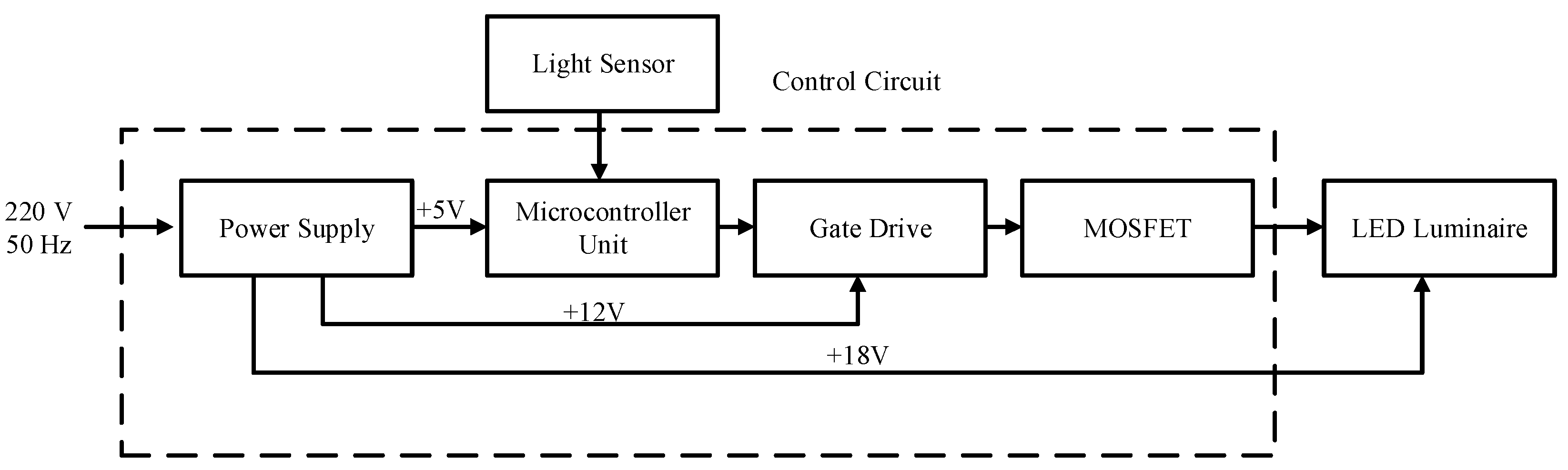
This research proposed a lighting control circuit in a lighting system integrated in LED luminaire based on a daylight control. The aim is to reduce energy consumption in lighting system while maintain the lighting quality on the working plane on the level that does not impact health and working efficiency of occupant. This research was divided into two parts: simulation and experiment on a prototype. The simulation with DIALux software aimed to show the advantages of the LED luminaire as compared to conventional T5 fluorescent that widely used in Thailand’s building. The experiment on a prototype was an actual physical test for evaluating the daylight control circuit performance in LED luminaire in terms of electrical parameters and lighting quality. Electrical parameters—voltage, current and power—were measured with a power meter. Illuminance on a working plane was measured with a lux meter. This paper is organized as follows.
Section 2 presents the DIALux software simulation of both LED and T5 fluorescent luminaire. The lighting control circuit, its operation sequence and experimental setup are discussed in
Section 3. Results from the actual field test are presented in
Section 4. Finally, the conclusion of this research is provided in
Section 5.
2. Simulation
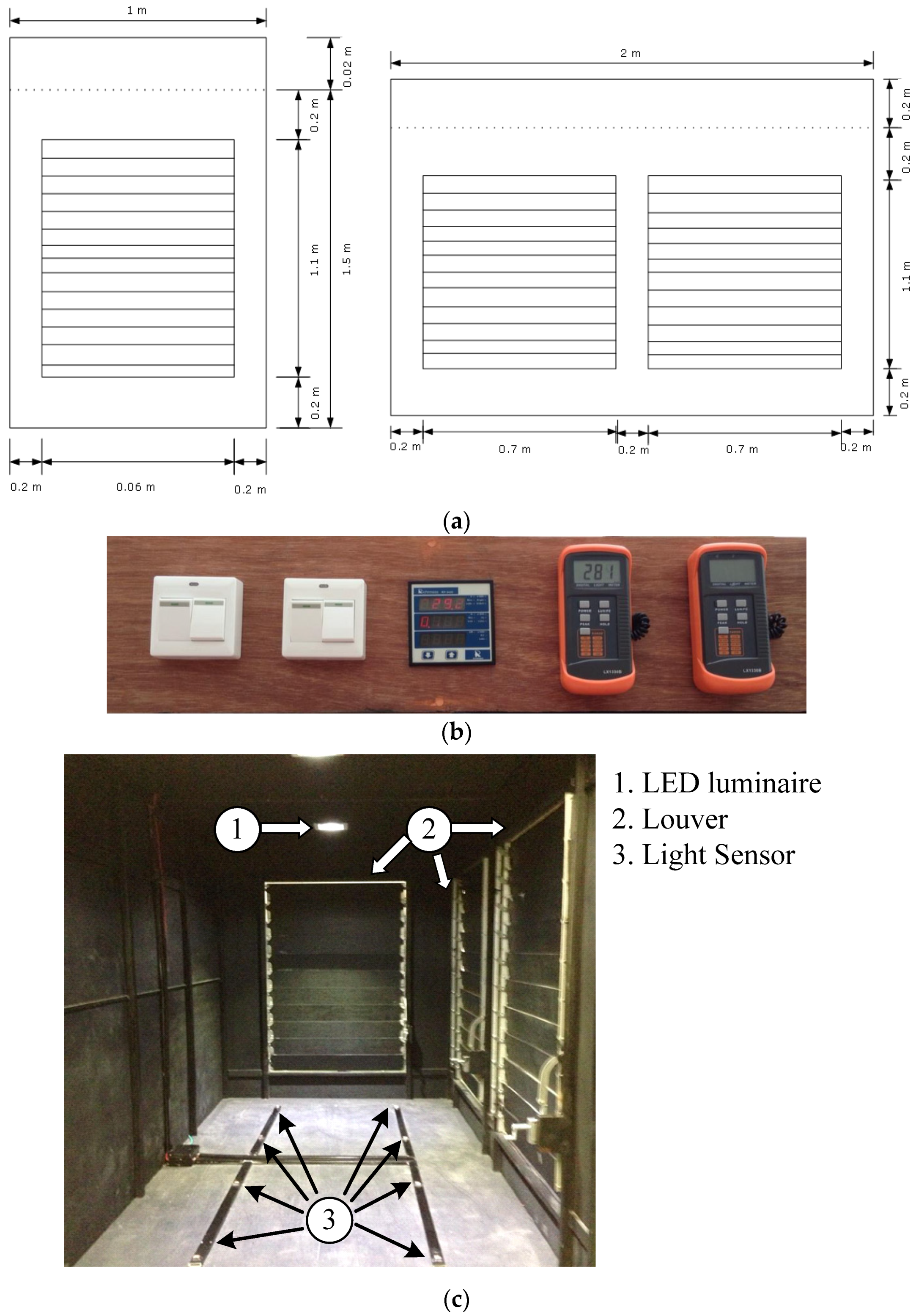
The simulation of light distribution profile using DIAlux software has been done in two aspect. First part is the simulation on the on the case study room and the second part is the simulation on the experimental setup. The case study room has dimension of 8 m × 12 m × 3 m (width × length × height). The room consists of 9 windows with a size (not include frame) of 1 m × 1.1 m. The overall layout of the case study room is shown in
Figure 1.
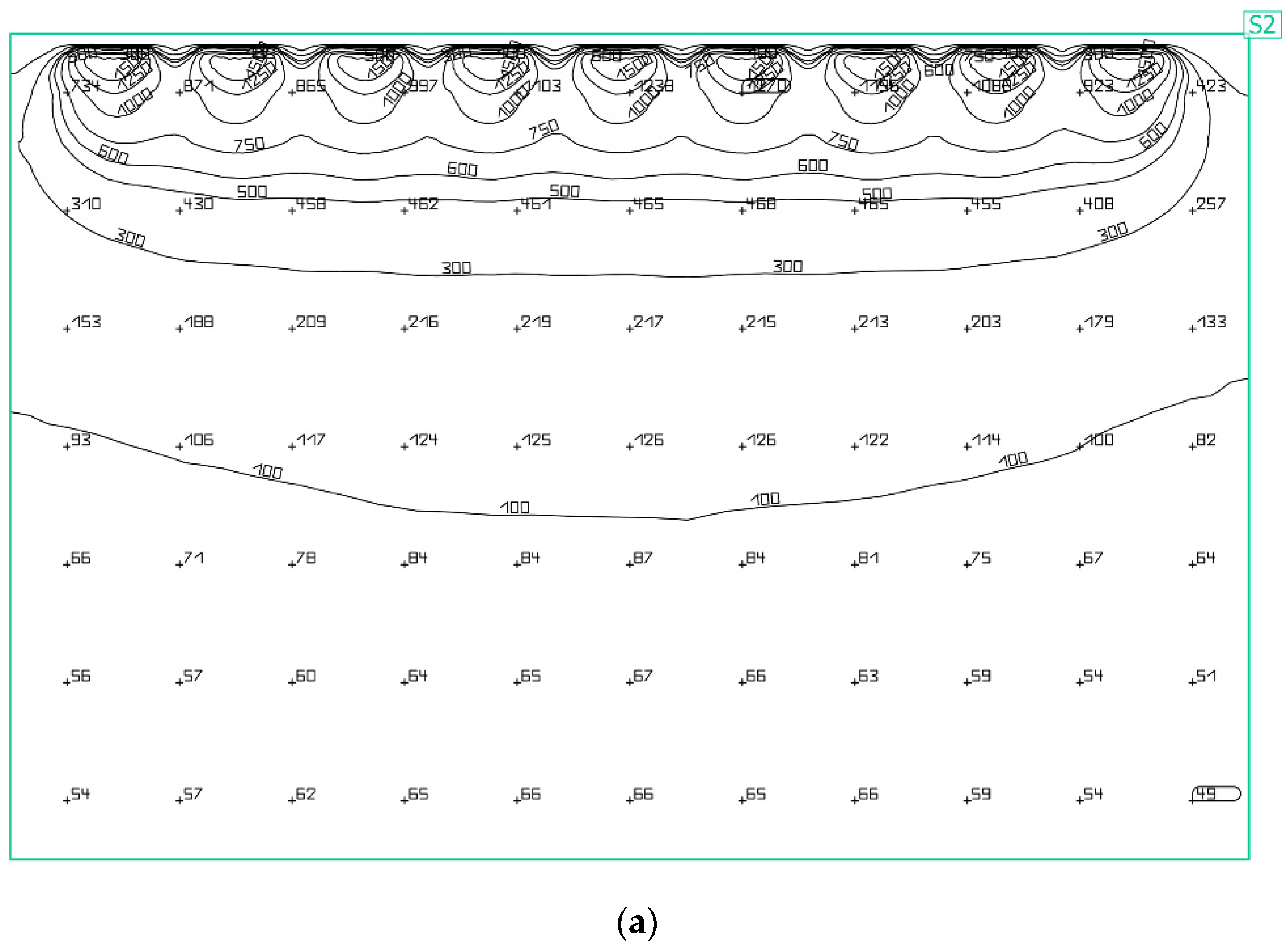
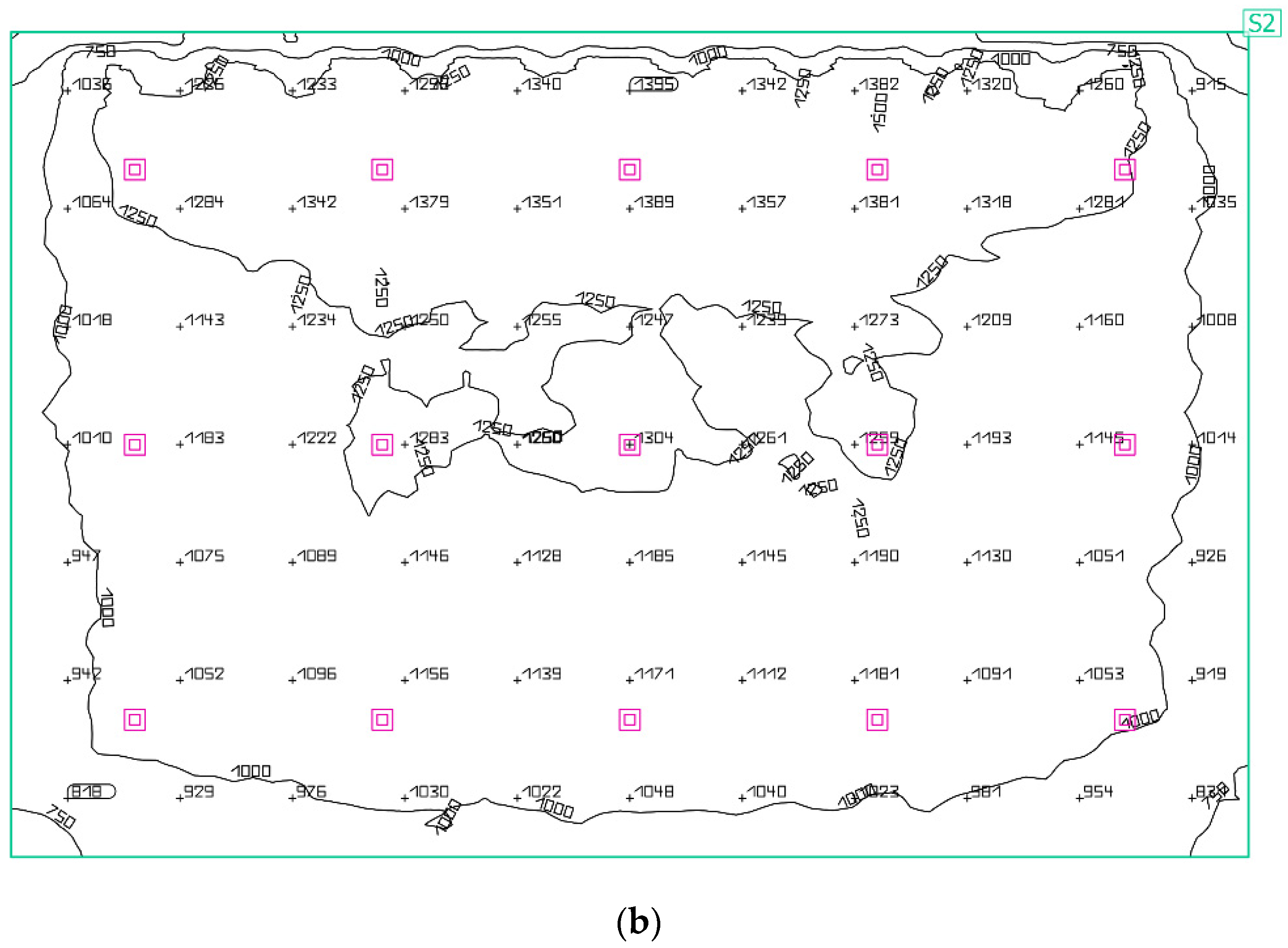
The result of daylighting on the case study room with only daylighting and with both daylighting and artificial lighting is shown in
Figure 2a,b respectively and the summarizing result is shown in
Table 1. The figure shown an example in case study room located in Bangkok, Thailand simulated at 10:00 AM. With clear sky on the 20 January 2020 in order to replicate the experimental setup case. The result in case of daylighting only shown that the illuminance value are high only in the area near the window and the daylighting cannot pass through the inner part of the room, thus reduce the uniformity of the lighting and the lighting quality cannot maintain at the commission on illumination (CIE) standard. However, the case study with both daylighting and artificial lighting has shown that the average illuminance on working plane is higher compare to previous case with high uniformity. In this case, it can be seen there has been excessive illuminance on the working plane. Thus, the daylight control can reduce light output of the luminaire and reduce energy consumption on lighting system.
The illuminance of daylighting on working plane in case of window-side of the room facing different direction can be summarized as shown in
Table 2. From the table, it can be seen that buildings facing in the east and west directions will have a higher illuminance value compared to buildings facing in the north direction due to the pathway of sun movement. For the buildings facing the south direction, they have overall higher illuminance due to the location of simulate building (Bangkok, Thailand) alignment to the south of sun pathway. The illuminance value of the building facing east direction is higher in the morning and the building facing west direction has higher illuminance value on the evening. The result in terms of average illuminance has shown that during peak period daylighting can provide significant illuminance on working plane. However, the artificial lighting is still required in order to maintain the illuminance on working plane during the period that has low sunlight. To maintain illuminance within the international commission on illumination (CIE) standard at 300–350 lux, the artificial lighting does not necessary operate at maximum light output. Thus, the daylight control can be implemented to reduce energy consumption, while maintain lighting quality on the working plane.
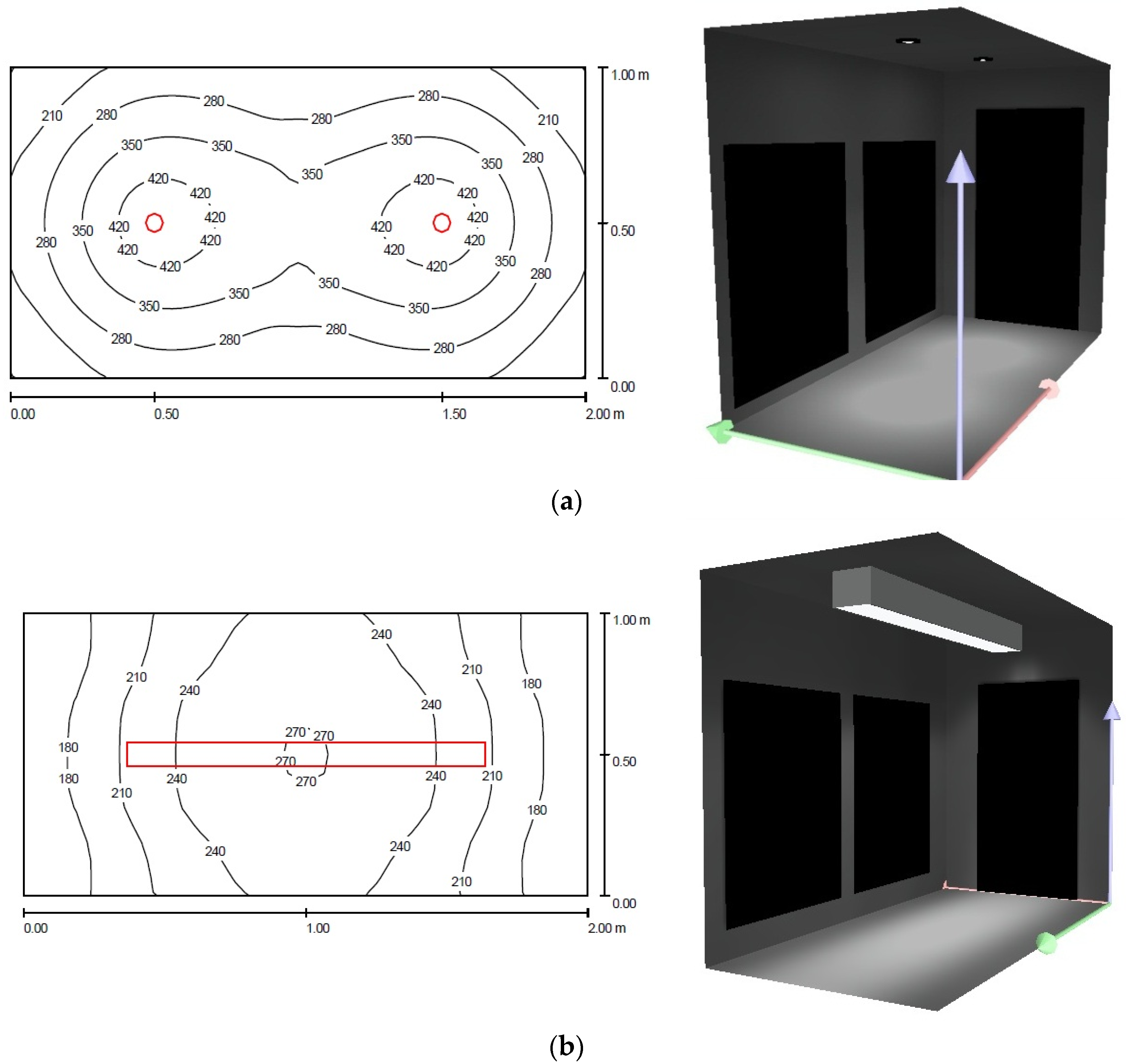
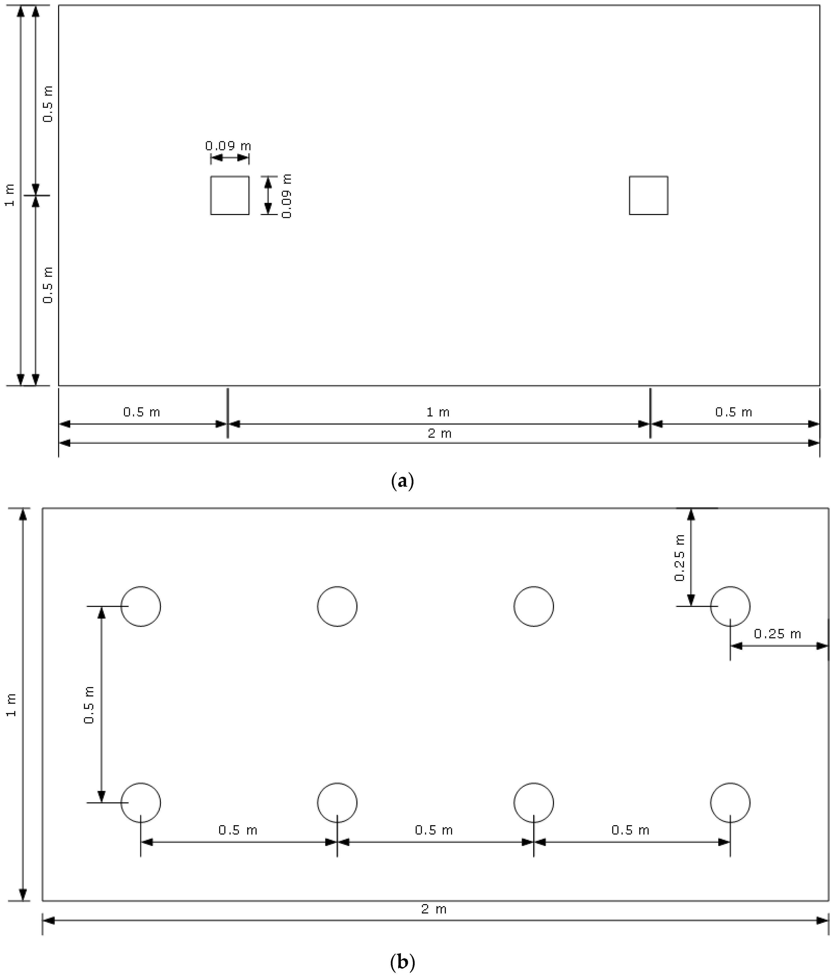
The simulation in second part is to evaluate the performance of an LED luminaire and a T5 fluorescent luminaire and their light distribution profiles on a working plane. The dimensions of the simulated room were 1 m in width, 2 m in length, and 3 m in height.
Figure 3a illustrated the LED luminaire (two sets of 3 × 3 W High power LEDs) location and its light distribution profile on a working plane 80 cm above the floor.
Figure 3b illustrated the T5 luminaire (36 W T5 fluorescent) location and its light distribution profile on the same working plane. A comparison between the light distribution profile of the LED luminaire and that of the T5 fluorescent luminaire revealed that the light distribution profile of the LED luminaire was better because of the higher light output from the LEDs. However, both types of luminaire could provide an illuminance that was within the international commission on illumination (CIE) standard at 300–350 lux.
Simulation results in terms of light intensity uniformity of LED luminaire and T5 luminaire are shown in
Table 3. In the case of the LED luminaire, the light distribution was a point. It could be seen that the light intensity at the ceiling and walls were low at 42 and 85 lux, respectively. However, in the case of T5 fluorescent, the light distribution was scattered in all directions. The luminaire’s light intensity at the ceiling and walls were 216 and 254 lux, respectively. For the light intensity on the working plane, the results were that the LED luminaire contributed higher illuminance at 294 lux compared to 202 lux contributed by the T5 fluorescent luminaire. Hence, it can be concluded that LED luminaire gave a better performance at the working plane and with less power consumption. Thus, it was the best choice to use with the daylighting control circuit to achieve even further efficiency and less power consumption.
4. Results
The experiment has been done at the Faculty of Engineering, King Mongkut’s Institute of Technology Ladkrabang located in Bangkok, Thailand (latitude 13°43′45.5″ North and longitude 100°46′32.0″ East) with the window-side of the experimental setup (with louver) facing the east direction. The experiment has been replicated three time under the same sky condition (clear sky) on the date of 19–21 January 2020 in order to verify the accuracy of the data.
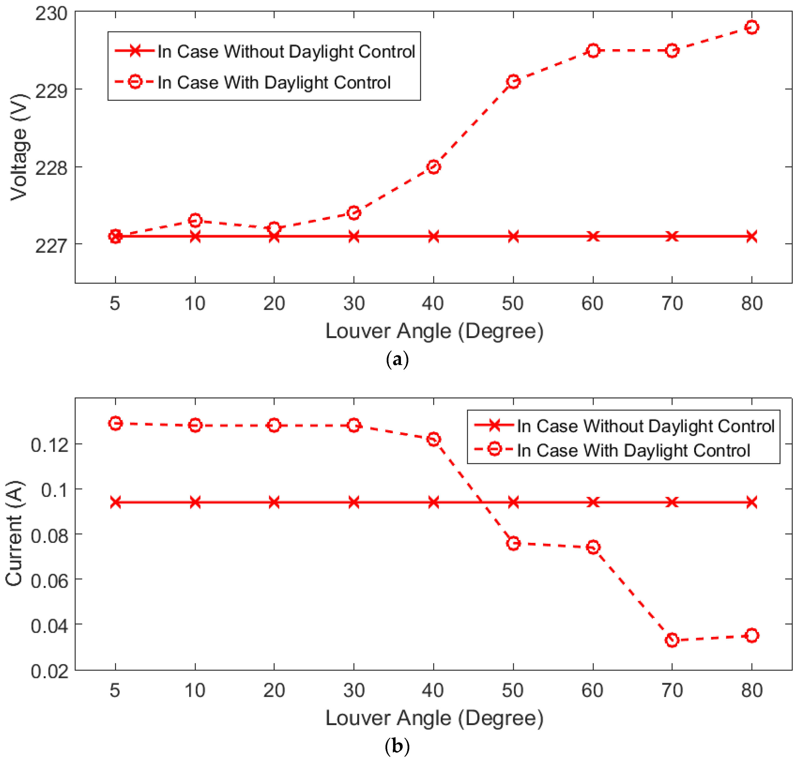
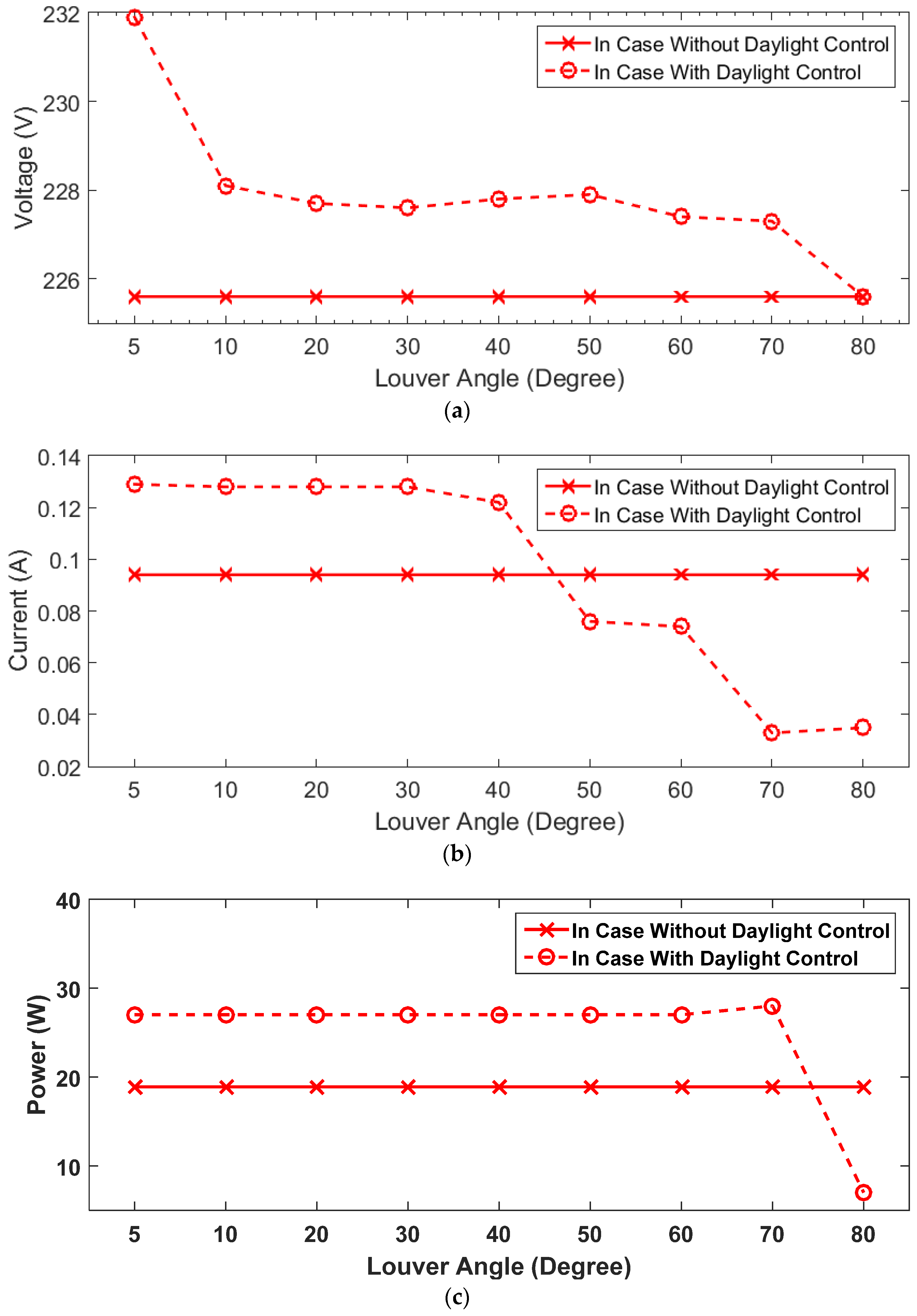
The result from the experimental setup in terms of the effect of louver angles on electrical parameters and illuminance at 9.30 A.M. has been obtained from the experimental setup. The relation between the louver angle and various parameters can be illustrated in
Figure 8. The electrical parameters consist of voltage, current and power as shown in
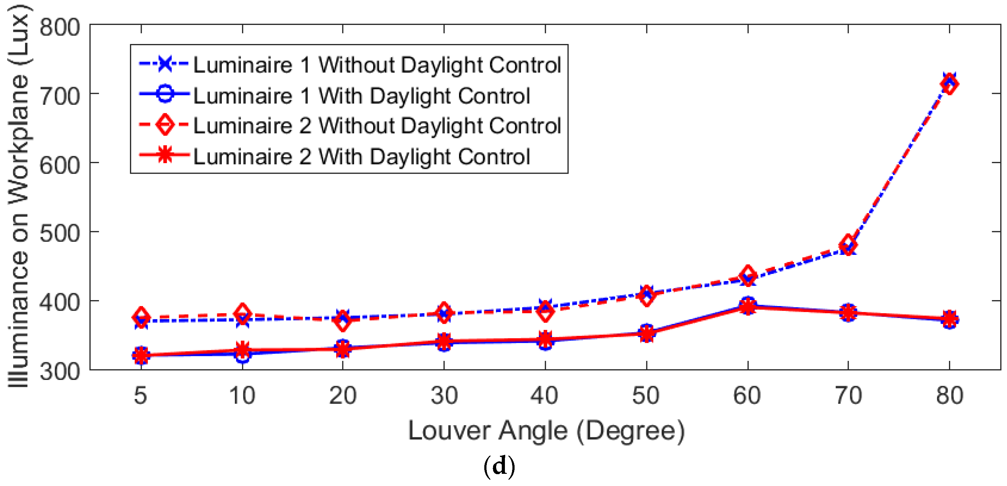
Figure 8a–c, respectively. When louver angle increases, illuminance from the workplace also rises due to daylight through experimental test room. This result in the control unit tried to maintaining illuminance value at 300 lux as setting value by steady reduced current and power to LED luminaire. The voltage level is steadily rising, but it does not have any effect on control circuit operation. This value has been further decreased as louver opens more than 40 degrees due to high daylight intensity in the workplace. The illuminance characteristics of two luminaire at various louver degrees are illustrated in
Figure 9d. From the figure, the value of luminaire 1 came from the luminaire located at the left-side of experimental setup and the value of luminaire 2 was located at the right-side of experimental setup according to
Figure 5a. The result shows that illuminance in the case without daylight control circuit has been steadily increased as louver angle increases, and it immediately rises when the louver opens more than 80 degrees. When installing a daylight control circuit, it can be seen that illuminance has been reduced compared to the previous case without the control circuit due to the setting in algorithms that specified illuminance value at 300 lux.
For the actual field test at 1.00 P.M., the experiment data in terms of electrical parameters and illuminance are shown in
Figure 10 with the relation between louver angle and various parameters. The electrical parameters are voltage, current, and power as depicted in
Figure 9a–c, respectively. When the louver angle increases, the voltage, current, and power have been steadily reduced, and it is immediately reduced significantly when louver opens more than 80 degrees due to increasing illuminance on the workplace from daylight, thus the control circuit reduces power for LED luminaire in order to regulate the light output from artificial lighting. Illuminance characteristics described in
Figure 9d show that illuminance in the case without daylight control circuit has been a steady increase as louver angle increases and it immediately rises as louver opens more than 70 degrees. When installing a daylight control circuit, the illuminance is also reduced similarly to the 9.30 A.M. period. This result reveals that louver angles have a significant effect on daylighting control circuit performance over a period of a day.
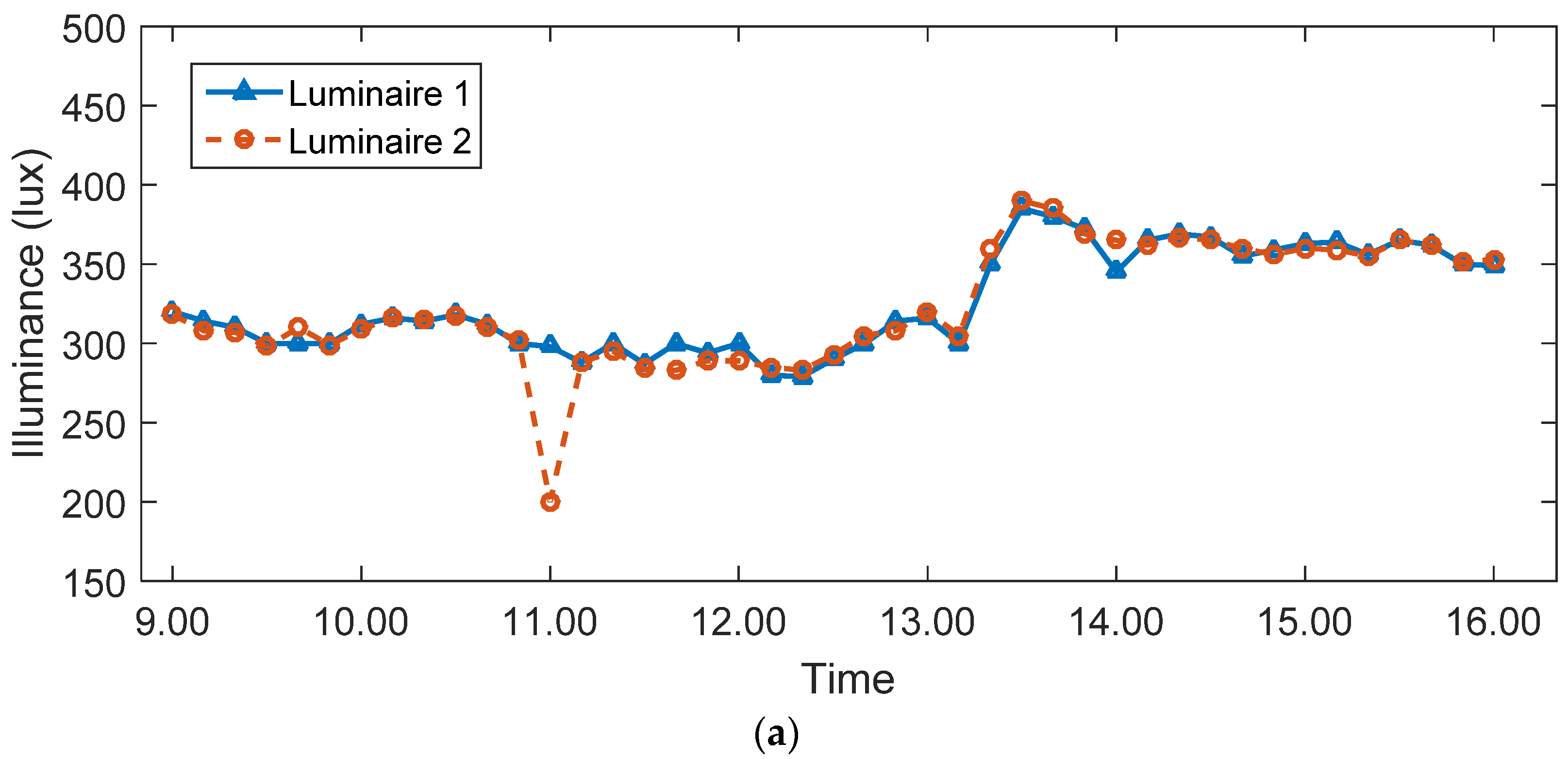
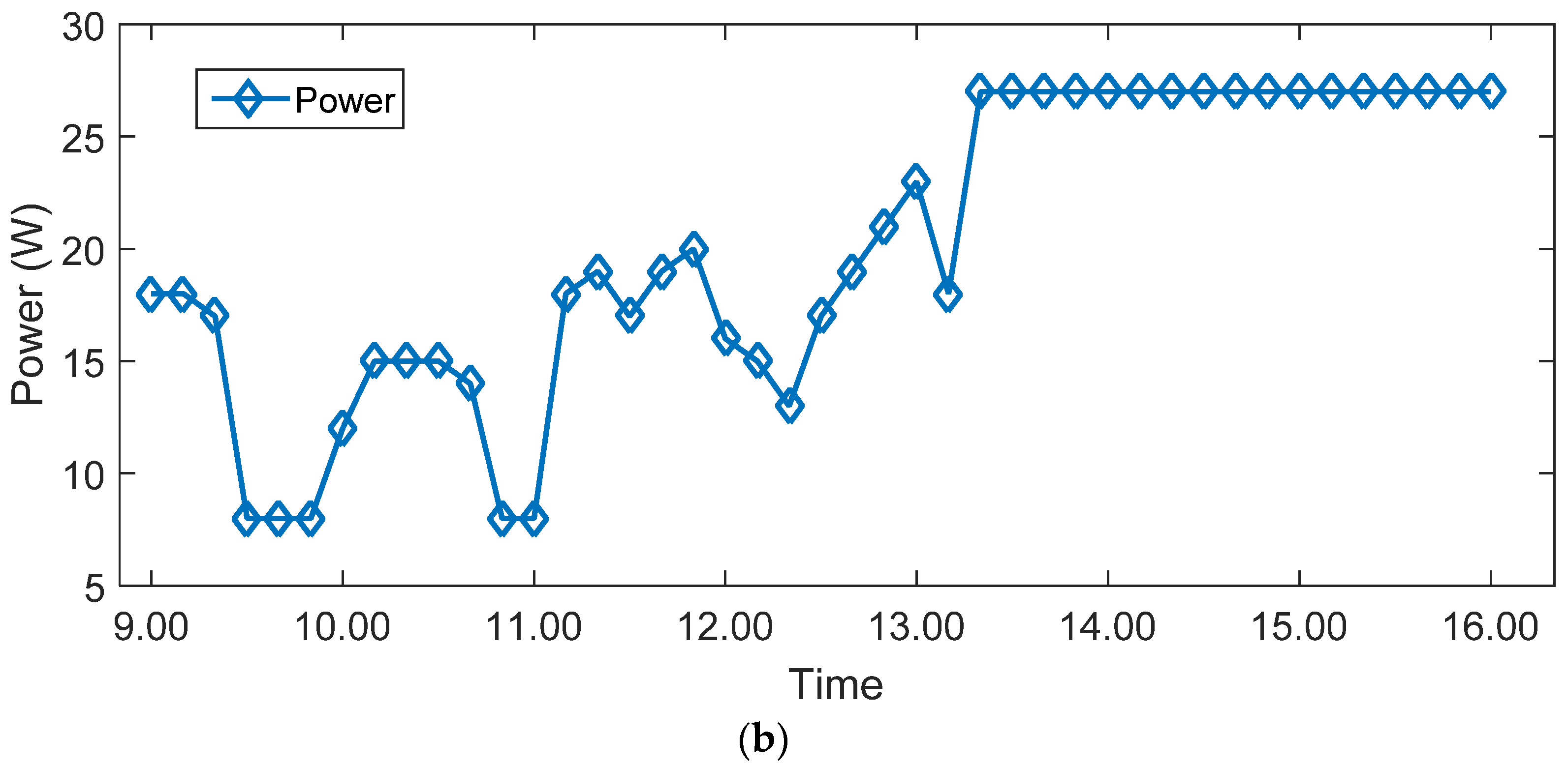
The effect of time on daylight control circuit performance is evaluated by obtaining power consumption and illuminance from LED luminaire every 10 min from 9.00 A.M. to 4.00 P.M. The experimental setup is with louver facing east direction. The characteristics of an LED luminaire in terms of both illuminance and power consumption in the experiment setup with a daylight control circuit over a period of one day is illustrated in
Figure 10a,b, respectively. It can be seen that the daylight control circuit can operate at the full capacity from 9.00 A.M. to 1.00 P.M., while at the period 1.00 P.M. to 4.00 P.M. the daylight control circuit cannot operate. The reason is in the afternoon, sun moves toward the western direction and the experimental setup does not consist of louver in that direction, leading to low daylight through louver, hence LED luminaire operates at maximum power in order to achieve setting illuminance around 300 lux. The proposed daylight control circuit can reduce power consumption in an experimental setup to 8W with both LED luminaires in some periods of time and is able to regulate illuminance within CIE standard value.
5. Conclusions
This paper proposed a daylight control circuit in LED luminaire and evaluated its performance in terms of power consumption reduction and maintaining illuminance value on the working plane using both simulation and experimental setup. The simulation of luminaire performance and effect of daylighting on working plane has been done using DIALux software in the aspects of both actual room and experimental setup that replicate parts of the actual room. The simulation results have shown the effectiveness of daylight in providing sufficient illuminance on working planes in areas near the window, thus reducing the power consumption of the artificial lighting by limiting the light output from the luminaire while maintaining the uniformity on the working plane.
In the case of the experimental setup, the proposed daylight control circuit prototypes and experimental setup for an actual field test have been built. The research has been divided into two parts: the effect of louver and effect of the time period on daylight control circuit performance in terms of both electrical and illuminance characteristics. The louver has a significant effect on control circuit performance. As a result, it reveals that with a higher louver angle, it results in high illuminance due to more daylight inlet. Thus, the control circuit reduces power to LED luminaires to maintain desired illuminance on a working plane. The effect of the time period showed that in the morning period, the control circuit reduces light output from LED luminaire. However, in the afternoon period, daylight inlet is less due to the direction of sunlight. This results in the control circuit having to operate at full capacity in order to maintain illuminance at the required value.
Results obtained from the actual field test using experimental setup have showed the effectiveness of the proposed daylight control circuit for LED luminaire under differential conditions. It can maintain the required amount of illuminance on the working plane during the daylight condition, while significantly reducing power consumption. This has illustrated the potential of using daylighting on lighting systems to improve building efficiency while maintain lighting quality on for the occupant. So, future work can implement the proposed daylight control circuit in actual buildings to demonstrate the improvement of energy efficiency in a lighting system.


