1. Introduction
Israel is currently investigating a possible geologic repository site to dispose of nuclear waste generated from research reactors. Long-term nuclear waste storage (temporary) and disposal (permanent) present a challenge around the world [
1]. The long-lived toxicity of radioactive heat-generating waste, or high-level waste (HLW), requires long-term planning for its isolation from the environment [
2]. Geologic repositories have been identified as a viable method for HLW disposition by the international community [
3]. Experts from the International Atomic Energy Agency (IAEA) and the Nuclear Energy Agency (NEA) have come to a consensus that the burial of HLW in deep geologic repositories provides appropriate protection from the biosphere and is technically viable [
4]. Geologic repositories can take the form of mined cavities or boreholes into which canisters of waste are placed. HLW can refer to either spent nuclear fuel or left-over material from spent fuel reprocessing that generates heat due to radioactive decay. HLW requires deep geologic isolation, unlike low- and intermediate-level waste (LLW/ILW) that may be disposed of in shallow facilities due to lower long-term safety risks to human and environmental health [
5]. While there are currently no HLW disposal facilities in operation, there are several facilities in demonstration and/or construction phases in other countries such as Finland, France, South Korea, and Sweden [
6]. Additionally, transuranic waste (TRU) is being disposed of in a deep geologic repository at the Waste Isolation Pilot Plant in New Mexico, USA [
7]. Existing HLW awaits final disposal in temporary facilities, and a feasible option for permanent disposal is a geologic repository.
Different geologic disposal designs have been investigated internationally with considerations to waste-type and geologic setting. Borehole depths can be categorized as shallow (above 200 m), intermediate (200–2000 m), or deep (below 2000 m) [
8]. Deep borehole disposal (DBD) designs have been identified as an appropriate way to isolate HLW, separated plutonium, and some specific fission product waste in sedimentary and crystalline rocks [
5]. The rock types in which borehole disposal has been proposed include clays [
9], crystalline rocks [
10], or salt deposits [
11]. Englert (2021) designed and modeled a DBD system in low permeability crystalline rocks where the vitrified waste form, steel canister, overpack, and bentonite borehole seal are the only barriers between the waste and the geologic media [
10]. Even with this moderate engineered barrier, the geologic cover and low hydraulic gradients at depth were found to be sufficient to isolate the waste in the possibility of waste package breach due to corrosion. The scientific consensus indicates that if DBD is successfully designed, there is little risk for long-term health and safety issues because deep stagnant brines do not easily interact with the biosphere [
12]. While DBD isolates waste from natural resources by emplacing it far below the water table, IBD (Intermediate Borehole Disposal) requires a greater reliance on both engineered and natural barriers to limit waste migration. Ideal IBD sites will have dry, low-permeability rocks and a geochemical environment that reduces radionuclide mobility. Geochemical properties that affect radionuclide mobility include the alkalinity, pH, oxidation state of the pore water, and the sorption potential of rocks.
The Yamin Plain (YP) of the northeast Negev Desert of Israel has been identified as a potential site for constructing an IBD site because the hydrological and geochemical properties of the subsurface may provide an adequate natural barrier for radionuclide migration in the vadose zone and a safe geologic location for borehole storage [
8,
13]. The generally low permeability, high uranium-sorption capacity, and high pH and alkalinity buffering capacity of the shallow marine lithologies constituting the YP subsurface indicate that a proposed site in the Negev Desert may be favorable as a natural barrier to HLW migration. In particular, a ~28 m thick phosphorite layer has been identified to have high uranium-sorption potential through laboratory tests [
14,
15,
16,
17] and may represent an important geochemical barrier in the unlikely case of waste canister failure and migration of HLW into the rock surrounding the borehole [
8,
13,
14,
15,
16,
17]. Below the water table, a primary concern is lateral transport of radionuclides due to regional hydraulic gradients [
18,
19]. However, the proposed IBD site is located above the water table in the vadose zone; thus, radionuclide transport will be largely downward with the infiltrating water. Thus, the placement of the proposed borehole above lithologic layers with high sorption capacity, such as the phosphorite layer, is an important consideration.
Because the uranium-sorption capacity of the YP lithologies is an important factor for establishing the feasibility of the proposed disposal borehole, Dangelmayr et al. (2021) performed uranium batch sorption laboratory tests on lithologies in the horizon of the proposed IBD site [
14]. The results indicate that non-linear sorption isotherms best predict the sorption behavior of the experiments and mechanistic surface complexation models for sorption capture changes of sorption behavior under evolving chemical conditions. However, the shallow marine lithologies in the Negev Desert and YP are rich in calcite, which provides a buffer to pH and alkalinity changes, and the relatively stable chemical conditions justify the use of a linear partitioning coefficient (Kd), a non-mechanistic simplification of the sorption processes, to describe the sorption behavior for the YP lithologies. It should be noted that methods to measure the sorption properties of rocks are still being developed because most laboratory methods to measure sorption involve pulverizing the samples into powder to accelerate the equilibrium process which can take decades under natural conditions [
9]. Recently developed methods to measure sorption include through-diffusion tracer experiments for intact rock that typically result in smaller distribution coefficients [
20]. Nevertheless, the YP sorption experiments provide a useful dataset and sorption model to incorporate into a site-specific, field-scale uranium transport model.
Here, we present a uranium fate and transport model from a disposal borehole with conservative (high) leakage rates to investigate worst-case scenarios of
235U outflow. Field-scale tracer experiments and laboratory studies at the Nevada National Security Site (NNSS) have found that radionuclide transport can be faster than model predictions due to colloidal transport and, in some instances, “prompt injection” [
21,
22,
23]. Although we do not consider colloidal transport in this study, unknown transport processes are likely accounted for with our conservative model inputs.
This study integrates geologic information, uranium-sorption experiments, and hydrologic measurements on the local lithologies [
15,
16,
17] and includes climate scenarios to build a flow and transport model of the vadose zone around the proposed IBD site in the YP. The proposed disposal site is novel as there are no other studies evaluating IBD for HLW. These results will serve to guide future investigations and characterizations of the lithologies, as well as to build a safety case [
24], if warranted, for IBD in the Negev Desert.
2. Physical Setting and Geologic Setting of the YP
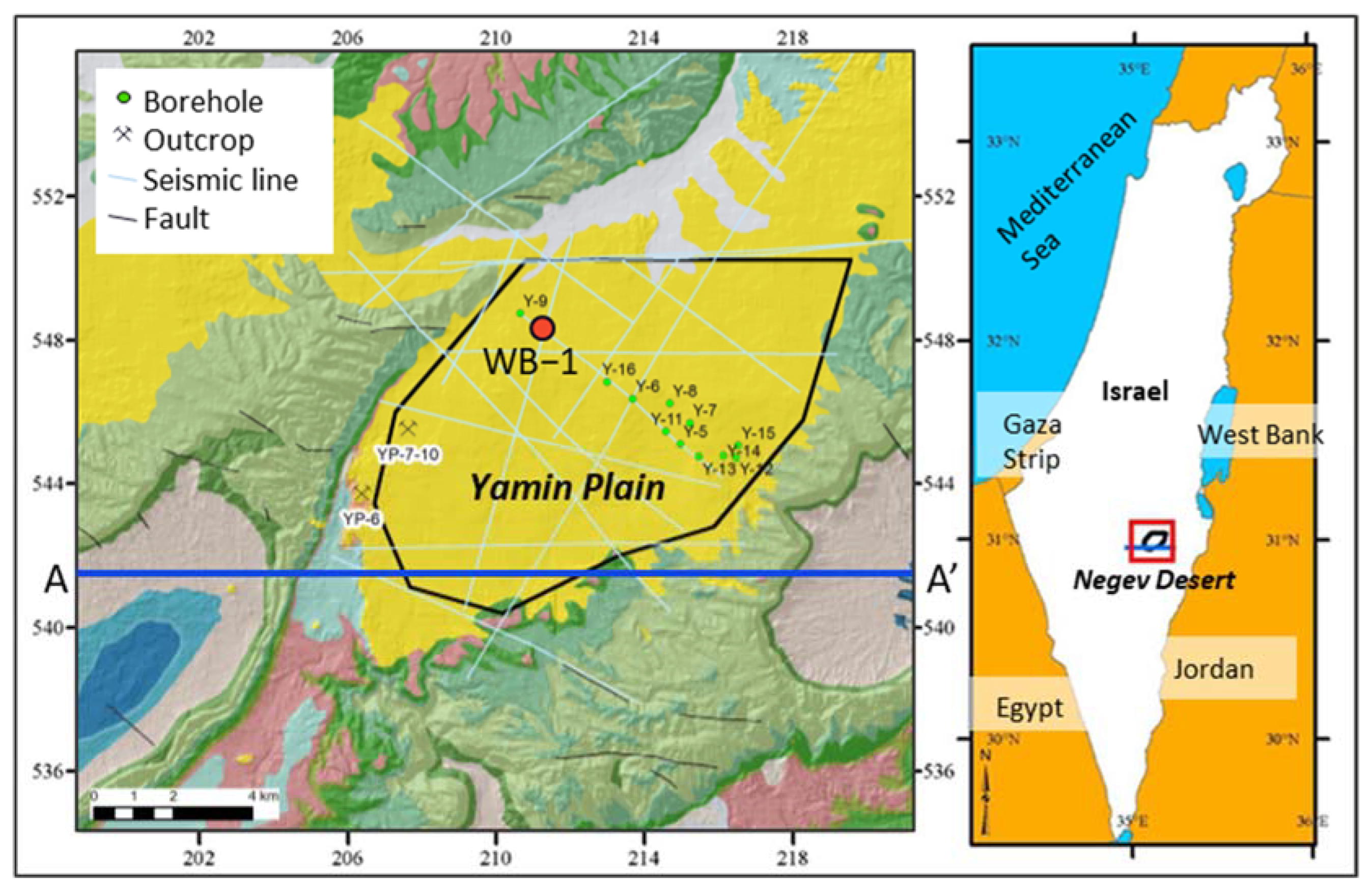
The proposed IBD site is located in the Yamin Plain in the northeast of the Negev Desert, Israel (
Figure 1). The YP is an alluvial basin with an elevation of 390–472 m above mean sea level. During the Upper Cretaceous, tectonic activity initiated the Syrian Fold Arc System which forms a series of synclines and anticlines. The YP is a syncline filled with syntectonically deposited sedimentary rocks (Mt. Scopus Gr.) that thin near the anticline axis (
Figure 2). The proposed borehole lies within the Menuha, Mishash, and Ghareb Formations of the Mt. Scopus Group, a 150–300 m thick series of shallow marine facies deposited in the YP basin during the Upper Cretaceous. Above the Mt. Scopus Group lays the ~200 m thick terrestrial clastic sediments of the Miocene Haveza Group [
25].
The climate of the YP is arid, with an average annual precipitation of 72 mm occurring over an average period of 15 days, and potential evaporation as high as 2600 mm/year [
26]. Although a perched groundwater lens containing modern ‘bomb-pulse’ tritium from atmospheric nuclear testing in the 1950s and 1960s has been identified at a depth of ~90 m [
26], a field study in the YP has shown that the maximum measured infiltration depth under extreme precipitation events is 4.5 m and concluded that long-term infiltration to the regional aquifer is negligible under current climate conditions [
27]. The regional groundwater table is estimated to be 500 m below the ground surface of the YP and is hosted in limestones and dolomites of the Middle Cretaceous Judea Group [
28].
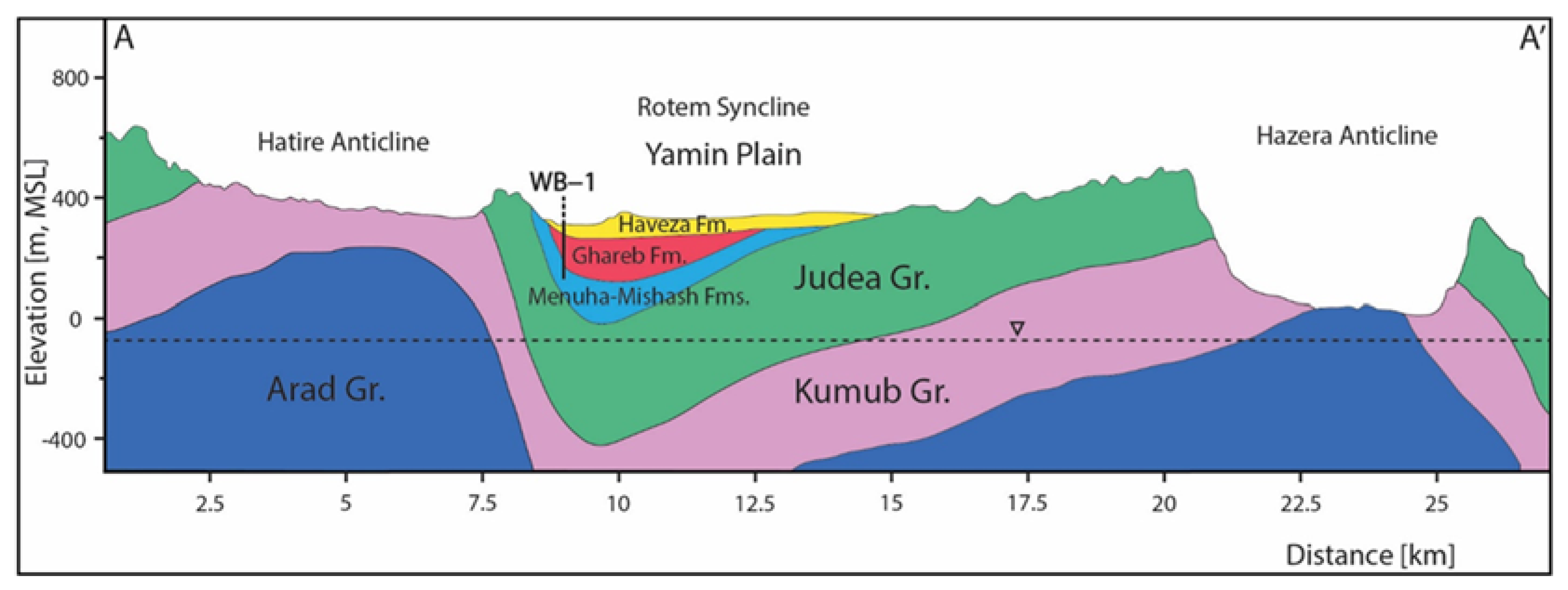
Figure 2.
The regional geologic cross section along A−A′, adapted from Calvo et al. (2019) [
28]. The approximate location of the exploratory borehole and proposed IBD is marked as WB−1. The overall stratigraphy used in our model represents a sequence of Late Cretaceous shallow marine sediments that were deposited syntectonically and where both marine and terrestrial sediments are present. The Arad Group is principally composed of carbonate rocks. The Kurnub Group consists of thick clastic units (sandstone and silt). The Judea Group consists of alternating limestone, dolomite, and marl. From bottom to top, the shallow marine Mt. Scopus Group includes a basal chalk unit (Menuha Formation) overlain by a chert-phosphorite-porcelanite unit (Mishash Formation) and bituminous marls in the upper most section (Mishash and Ghareb Formations). The upper section of the Mt. Scopus Group is truncated by an erosional unconformity above which Eocene and younger sedimentary units of the Hazeva Formation (mostly sandstone, clays, and conglomerates) cover the entire basin (YP).
![Geosciences 13 00166 g002]()
3. Materials and Methods
The numerical model of the proposed IBD integrates data from a characterization borehole drilled in 2022 (WB−1) near the proposed waste disposal site. Thicknesses of and contacts between the lithologic units identified in the borehole provide the basis for the six lithostratigraphic units represented in the flow and transport model. Flow properties were determined by the laboratory characterization of previous core samples (borehole Y−16) and regional outcrop samples, in-situ borehole pressure tests, and values obtained from analog samples found in the literature when site-specific data was unavailable (
Table 1) [
15,
16,
17]. Two phosphorite parameter sets (varying permeability and porosity) were tested: Case 1 is a high permeability phosphorite whose properties were determined from a laboratory test of an outcrop sample collected kilometers away from the proposed borehole [
15], and Case 2 that assigns phosphorite a lower permeability and porosity based on observations of the WB−1 core. The Case 2 values are placeholders until data from laboratory analysis of the WB−1 core becomes available. The two cases represent end members of the flow and transport properties of the phosphorite layer, the lithology with the greatest sorption potential. These end-member cases allow us to bracket uncertainty in uranium transport behavior around this valuable, natural chemical barrier.
Observations of the WB −1 core indicated a highly fractured region within the bituminous marl. The bituminous marl fractured layers were given the same rock properties (porosity, density, relative permeability models) as the unfractured bituminous marl except for the permeability that was estimated from borehole pressure tests within the fractured interval. Regional vertical joints and fractures have been identified by our team in the YP but are not represented explicitly in the flow and transport models. Mineralized fractures with calcite were observed within the WB−1 core but were not included as flow paths in the model.
The uranium transport model incorporates sorption coefficients informed by uranium sorption and desorption experiments that were performed on representative Negev Desert rock samples [
14]. Due to the strong pH and alkalinity buffering capacity of Negev Desert carbonates studied, a non-mechanistic, linear partitioning coefficient (Kd) for uranium sorption is an adequate approximation and greatly reduces computational complexity. The chalk, bituminous marl, and phosphorite samples exhibited intermediate to high uranium sorption capacities (i.e., Kd = 20–422 L/kg) [
17].
To simulate a waste canister breach scenario, a 3D probabilistic flow and transport model was created to assess radionuclide flow and transport behavior around a hypothetical waste disposal borehole in the Negev Desert subsurface. Flow and transport simulations were performed using PFLOTRAN [
29] solving for 3D, isothermal, multiphase flow (air and water), and uranium transport. PFLOTRAN has a built-in Used Fuel Disposition Decay Process Model where uranium decay is implemented. However, the decay of uranium has a negligible effect on the transport due to the long half-life (700 Ma) compared to the simulation time of 1000 years.
Variability of permeability and porosity was incorporated into each of the model’s lithologic units using Geostatistical Software LIBrary (GSLIB) [
30] to perform geostatistical sampling. Permeability and porosity values are allowed to vary by up to 10% around the mean value (see
Table 1), producing heterogeneities in each layer and also allowing for thin, laterally discontinuous lenses to capture the variability of interlayered sequences. Linear sorption coefficients and van Genuchten capillary pressure and relative permeability models are assigned to individual lithologies.
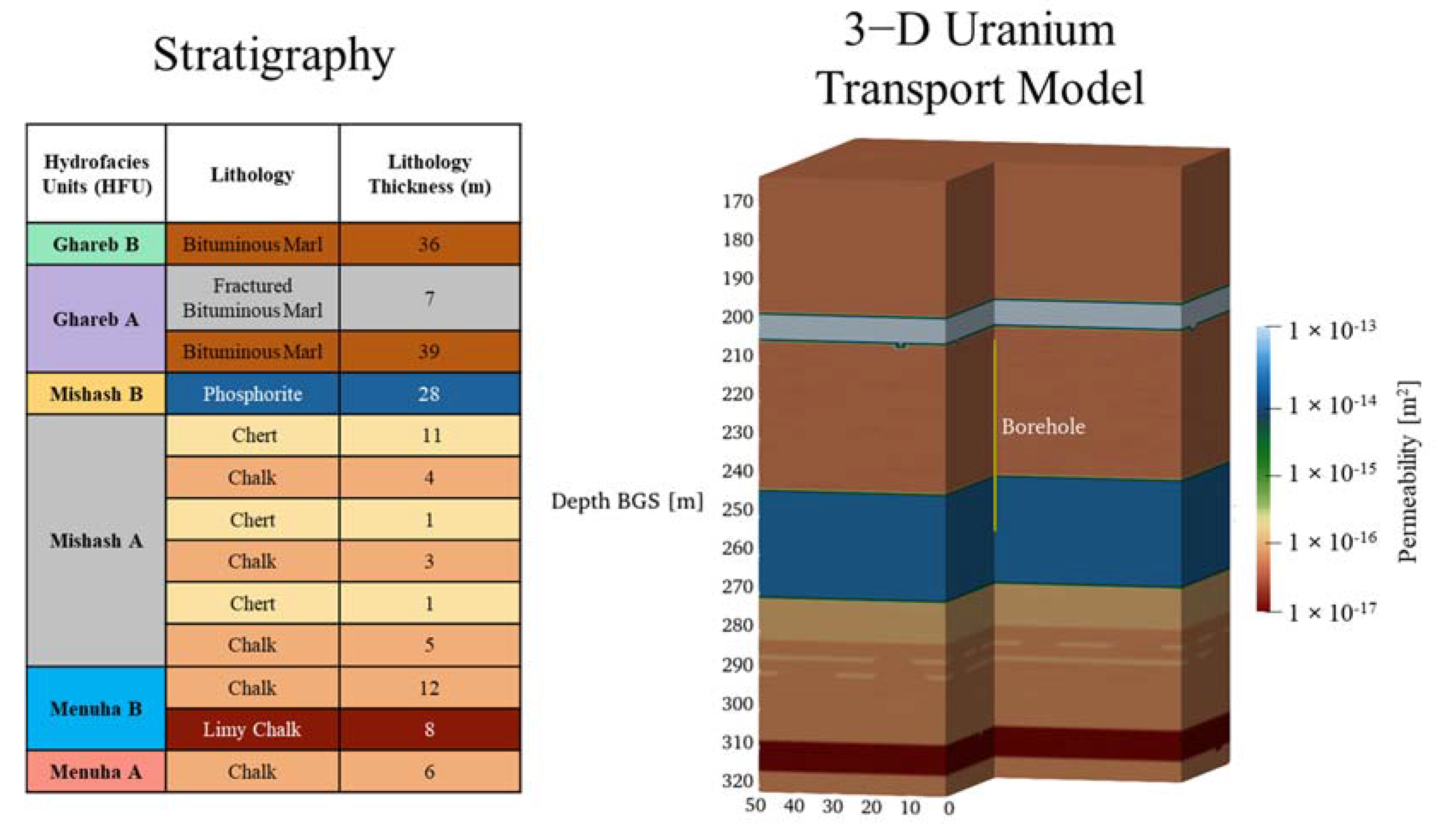
The computational mesh was generated using the Los Alamos LaGrit (V3.320) mesh generation software [
31] with a 100 m by 100 m lateral extent and 161 m vertical extent. The grid spacing was a uniform structure with 1 m
3 cells, resulting in 418,760 total nodes. The model structure and stratigraphy are shown in
Figure 3. The simulated borehole was situated in the center of the model (x = 0 m, y = 0 m, z = 207 m to 257 m) within the Ghareb A hydrofacies unit (HFU) that includes a bituminous marl and the phosphorite layer. It should be noted that the top of the model is 172 m below the ground surface and the bottom of the model is ~200 m above the water table. Based on previous calculations, the simulations assume that the ~172 m thick surficial alluvial deposit has an adequately high vertical permeability to transmit infiltration from the land surface to the top of our IBD model domain nearly instantaneously and with no lateral spreading [
16].
To represent a leak from a breached HLW canister, we simulated a total of 219 moles of
235U leaking from the borehole over the course of 1000 years. All simulations started from an assumed very low infiltration flux of 0.1 mm/year (0.1 L per square meter per year) to approximate the current climate. Three infiltration fluxes were then applied to different simulation scenarios to represent current and significantly wetter climate scenarios.
235U in the U(VI) oxidation state was chosen as a tracer because it is highly soluble due to the formation of uranyl species in natural environments. The amount of
235U leaking from the borehole was derived from published values of the activity of
235U within vitrified HLW [
32], assuming 50 m
3 waste and assuming that 10% of the waste leaks over 1000 years, resulting in 0.219 mol/year (52 g/year) of leakage. This amount of leakage represents a significant amount of stored HLW moving into the water around the simulated IBD and should be treated as a very unlikely scenario. The solubility of uranium is highly sensitive to its concentration and the chemical environment. Due to the uncertainty in the solubility relationships for this specific environment, a conservatively high solubility limit of 200 ppb was chosen based on literature values from around the world. We note that a single reported value of 1820 ppb has been found in natural groundwaters in New Mexico, USA [
33]. The solubility limit of 200 ppb is over 6x the U.S. Environmental Protection Agency (USEPA) drinking water maximum contaminant level (MCL = 30 ppb) for uranium [
34].
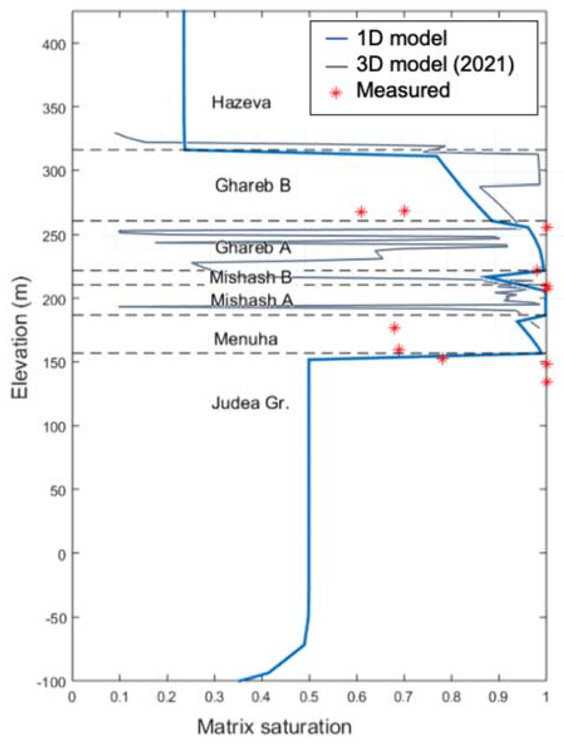
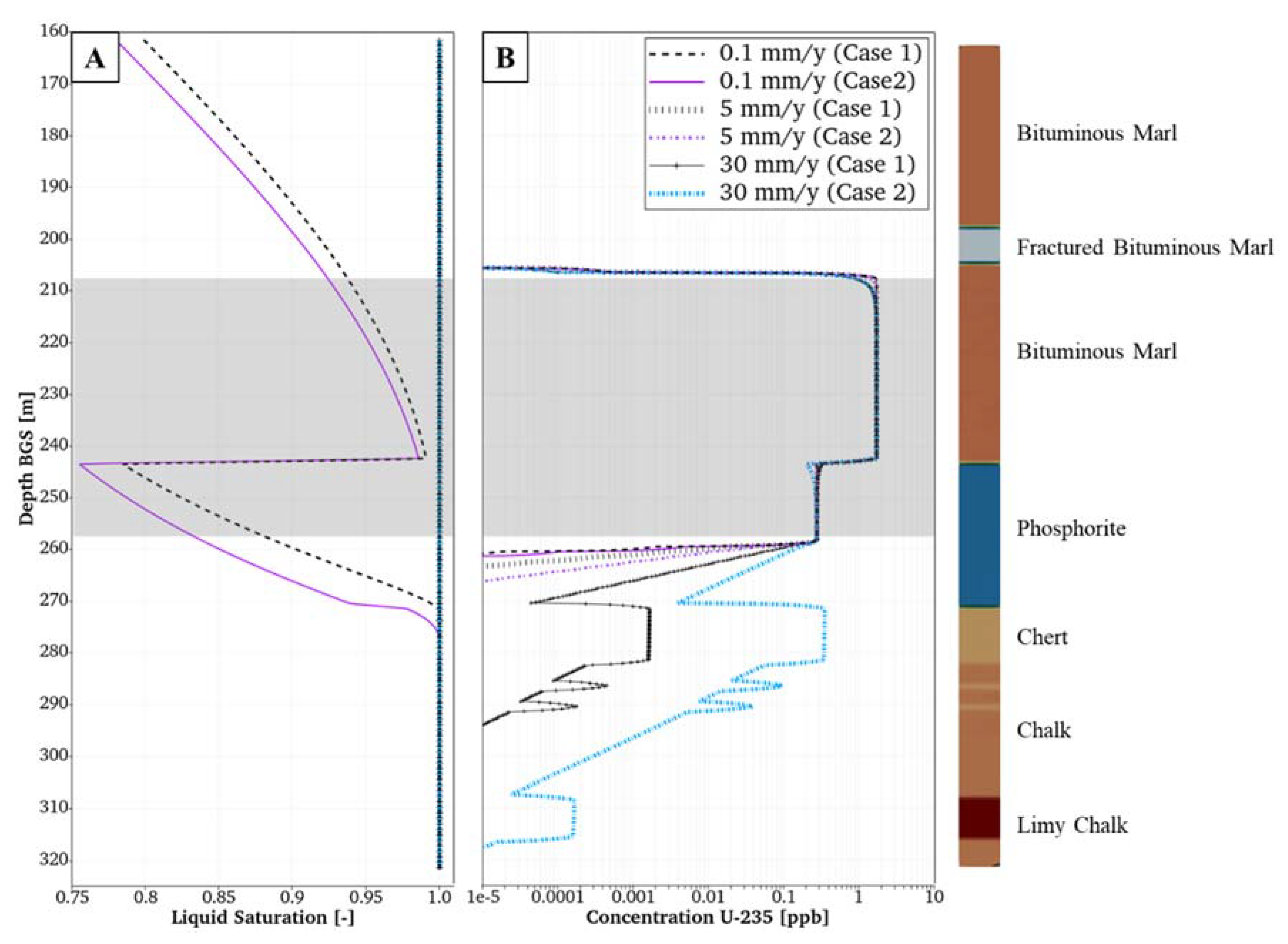
Saturations in the lithologic units of interest from Y−16 are generally wetter than would be predicted from steady-state saturations using an infiltration flux of 0.1 mm/year (
Figure 4). The initial saturation conditions for the transport model were generated by performing an initialization simulation that started with fully saturated conditions to represent the wetter conditions in the subsurface during the last glacial maximum. We then simulated 10,000 years of drainage with the assumed current infiltration flux of 0.1 mm/year applied at the top of the model. Observed saturations from Y−16 core data, an exploratory borehole drilled ~4 km from the WB−1 site (
Figure 4), showed general agreement with the simulated saturations. Although there is a saturation difference of up to 30% between model results and some field measurements, based on available data it is not yet feasible to capture the true heterogeneity of the system. As a preliminary step, we believe that the model/data comparison is reasonable. The assumptions used to generate the initial saturation profile will be reevaluated when WB−1 saturation measurements become available.
From the initial state, three infiltration scenarios were simulated to observe the effect of very arid to very wet climates that could drive uranium transport from the borehole. The infiltration conditions are: (1) 0.1 mm/year (current infiltration conditions), (2) 5 mm/year, and (3) 30 mm/year (wet climate scenario). These three infiltration scenarios were simulated for 1000 years with Case 1 and Case 2 properties, yielding a total of 6 simulations.
4. Results and Discussion
Our simulations show that uranium transport is sensitive to infiltration fluxes and sorption properties of the lithologies.
Figure 5A presents saturation profiles for the three infiltration scenarios after 1000 years. Saturation is important to understand because higher saturations can increase the relative permeability of water and hence, the mobility of liquid-phase
235U, increasing the potential for downward migration of a
235U plume. In the 0.1 mm/year scenario, the rocks are still drying from the initial state of saturation. However, even in the driest case, saturations remain above 75% in high-permeability layers and reach 100% for the lower permeability lithologies. Simulated saturation is lowest in the phosphorite layer when a low-permeability and dry climate is assumed (0.1 mm/year Case 2). Otherwise, the phosphorite layer is saturated under the wetter conditions after 1000 years in the 5 mm/year and 30 mm/year scenarios (
Figure 5A), allowing for greater mobility and potential contaminant migration away from the site.
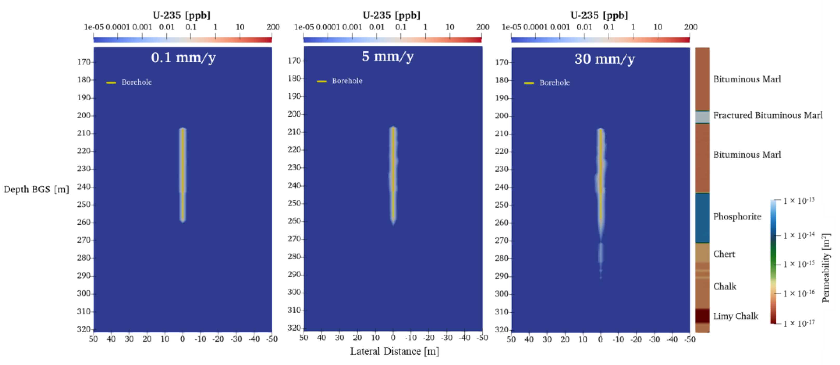
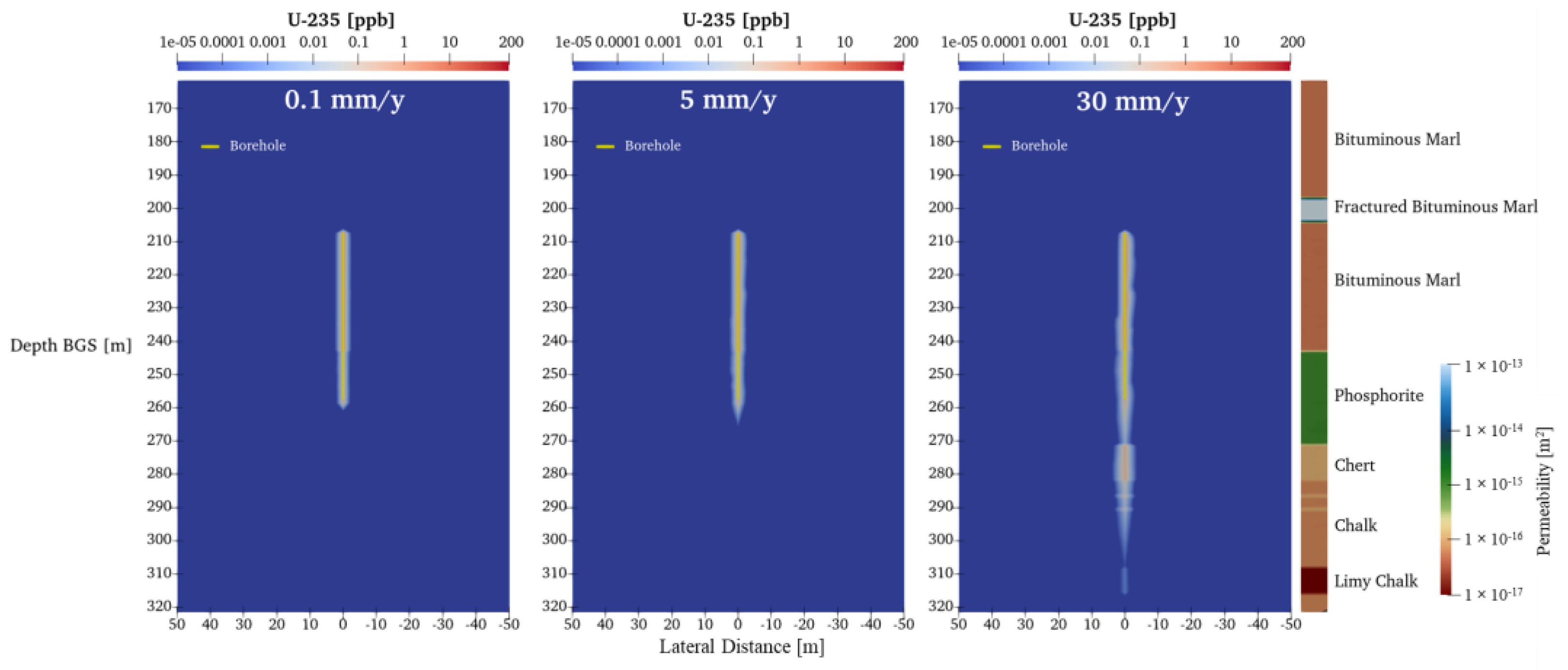
Because of the high sorption capacity for uranium, plume migration will be attenuated in the phosphorite unit (Kd = ~400 L/kg), especially under low- and moderate-infiltration fluxes (
Figure 5B,
Figure 6 and
Figure 7). Under the low-infiltration flux scenario (0.1 mm/year), the plume does not significantly migrate downwards from the borehole release location. Similar results occur under a 5 mm/year infiltration flux—the plume mainly stays near the borehole and there is limited migration of
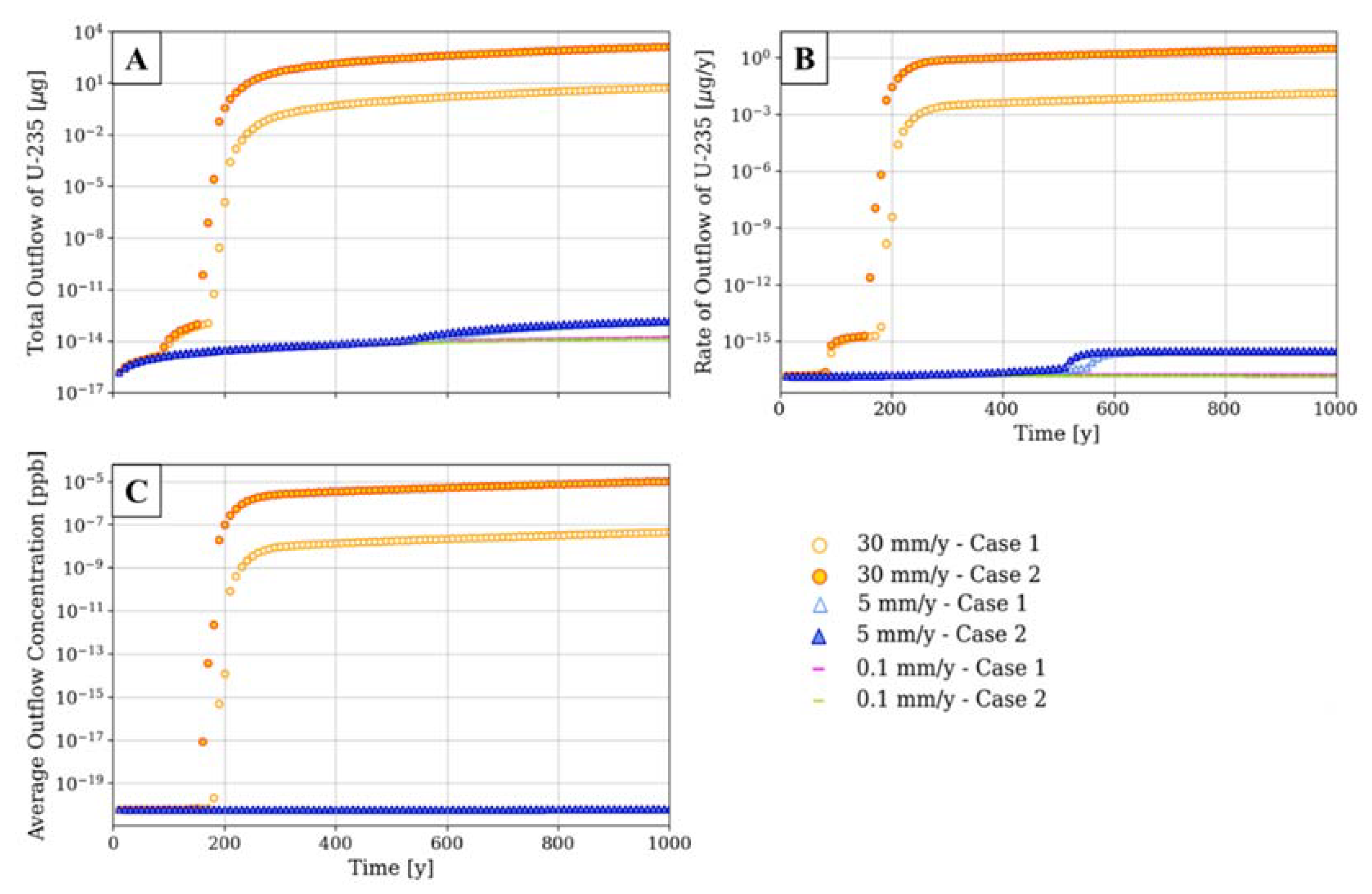
235U to depth. Under a 30 mm/year infiltration flux, downward flow drives migration of the plume into the phosphorite and chalk layers. However, the results show how storage in the phosphorite layer through sorption limits the vertical extent of plume migration; after 1000 years, only trace amounts of uranium leave the model basal boundary (5.8 µg in case 1, 1410 µg in case 2) (
Figure 8A).
In
Figure 8, the 0.1 mm/year and 5 mm/year scenarios have negligible
235U breakthrough after 1000 years while the 30 mm/year Case 1 and Case 2 show significantly different behaviors. At 1000 years, 242× more
235U leaves the model boundary in the Case 2 scenario than in the Case 1 scenario (
Figure 8A). However, the timescale of the breakthrough is the same, initiating at 150 years (
Figure 8A,B). The difference between the 30 mm/year cases highlights the effect of porosity and storage on the transport of
235U. The higher porosity of the rocks in Case 1 provides a greater surface area for
235U sorption and a larger volume of water-filled pores for
235U storage. These results show that a lower porosity/permeability rock may be less effective in attenuating radionuclides for which sorption is an important process.
With a low-end detection limit of 2.35 × 10
−5 ppb using sensitive instrumental analytical methods [
35], none of the simulations would be detected below the model boundary after 1000 years (
Figure 8C). The results highlight that sorption can provide a natural geochemical barrier for
235U plume migration, but under wet-climate scenarios, there is still potential for migration toward the water table. Climate-driven increases in infiltration could thus lead to the migration of contaminants to the regional water table. Due to the uncertainty of future climate, infiltration fluxes, and
235U-source term, more data and simulations are required to support the safety case for borehole disposal in the YP. Future simulations will incorporate lateral groundwater flow gradients under saturated conditions where lateral flow may be significant.
Ongoing work on this project relates to thermal simulations that include multiphase fluid/vapor/air migration caused by heat generation in the disposal borehole. Preliminary results show that the temperatures near the borehole have the potential to reach the windows for oil and gas generation from kerogen found in the bituminous marl [
36]. Furthermore, coupled heat and mass transport models can suggest that heat-driven convection in both liquid and gas phases will affect the near-field transport of radionuclides [
37].
Future work will include further hydrogeologic characterization of the WB−1 core to better constrain permeability and porosity values and heterogeneity, including a revisitation of the assumption of 10% variation. If the YP site is further explored via drilling for waste disposal, we will take advantage of additional core information to inform our geostatistical sampling. Additional simulations will investigate sensitivity to rock properties, sorption parameters, and climate/infiltration predictions.
5. Conclusions
Modeling results present an optimistic view of the feasibility of the Negev Desert as an intermediate-depth nuclear waste borehole disposal site. Three-dimensional uranium transport simulations show that for hypothetical uranium leakage from a disposal borehole, liquid-phase contamination would likely stay close to the disposal borehole and only trace amounts would migrate downwards under present dry conditions (0.1 mm/year infiltration flux) and for a moderately wet climate scenario (5 mm/year infiltration flux) over 1000 years. These results are positive considering the overly conservative assumptions of waste leakage. Assuming that the waste packages will be vitrified, low corrosion rates on the order of 0.1 μm/year in unsaturated conditions are expected [
38]. Depending on waste package configurations, it could take at least 500,000 years to completely corrode, even after a steel canister breach [
39].
A wetter future climate scenario (30 mm/year infiltration flux) leads to some migration of uranium below the bottom boundary of the simulation domain. Two end-member cases for a high sorption phosphorite layer show the combined effect of porosity, permeability, and adsorption on uranium migration. In rock types with high sorption potential, a higher porosity can be more effective at attenuating 235U due to increased surface area and storage volumes, even if a high permeability is also assumed. Future efforts will focus on implementing characterization data from a borehole completed in 2022 into the models, including laboratory measurements of permeability, porosity, non-linear relative permeability behavior, and saturation. The continuation of this work will inform the safety assessment of the Negev Desert as an intermediate-depth borehole disposal site.
_M._Sharp.png)


 ,
, 


