1. Introduction
Rockfall is a common cause of traffic delays, structural damage, and, occasionally, fatalities in mountainous areas. A rockfall can be triggered by landslides [
1], earthquakes [
2], jointing, chemical degradation and weathering [
3], water effect, freeze–thaw [
4], and tree roots [
5]. Rockfall protection systems are used to reduce the risk of rockfalls. These systems include active mitigation, such as designed rockfall protection systems that are capable of containing rocks in order to reduce danger, as well as passive mitigation, such as investing in rockfall barriers that mitigate the damage by dissipating the energy of the rock once a rock detachment has occurred [
6]. Earth dams, nets, ditches, sheltering structures, and reinforced concrete (RC) barriers have been built as passive protection measures in areas that are vulnerable to such dangers, including many regions of Switzerland, France, northern Italy, Ohio State of Japan, South China, and some overcrowded Asian metropolises such as Hong Kong [
7,
8,
9]. In the literature, rockfall barriers are broadly categorized as either rigid or flexible [
10]. Rigid barriers are made of materials such as masonry, stone, brick, or earth dams. Reinforced concrete barriers with sliding or anti-slide base and pile wall systems are also considered rigid barriers. Flexible barriers include draped mesh systems, rockfall fences, and rockfall attenuation systems [
11]. The selection of a particular type of protection method typically depends on various factors, including the application, slope angle, hazard intensity, terrain characteristics, material availability, constructability, and available budget.
In current practice, baffles (inflexible vertical columns) that can be arranged in a configuration consisting of multiple rows and are positioned on slopes or flat surfaces in basins are used in the design of debris flow barriers. The purpose of these baffles is twofold: (i) to reduce the speed of debris flow [
12,
13,
14,
15]; and (ii) to remove (filter out) large and coarse boulders from the debris [
16,
17]. Although baffle arrays are frequently employed in landslide mitigation, their design is prescriptive. In reality, current guidelines [
18,
19] do not link the placement of baffles with their intended use, whether for capturing or controlling discharge. The design of these baffles is currently based on experiments or numerical simulations. The interaction between the particle flow and the array of baffles structure is studied through laboratory experiments [
12,
15,
20,
21] and numerical simulations [
12,
22,
23,
24,
25,
26]. Some design guidelines are available for debris flow-resisting baffles [
19]. The design of debris flow barriers is still challenged and practice-based due to the lack of specific national standards, and only Hong Kong and Austria have made significant contributions to the development of reliable structure design methods [
19,
27]. Trees grown in these trajectories can also act as a natural baffle in an event of rockfall [
6,
28,
29]. The function of the baffle is similar to the function of a catchment ditch in the construction of an earth embankment [
8].
The current design of baffle structures subjected to boulder impact is essentially empirical. There is only limited published research on the impact mechanisms and failure of a baffle and footing resulting from dynamic boulder impact. In one study, analysis of a steel baffle mounted on concrete footing with dowels under the areas of boulder impact has been studied for boulder impact experimentally and numerically [
30]. Mounting steel columns on a concrete foundation is also a common design in flexible barriers; however, the post is vulnerable to boulder impact and attention to the design of these steel poles and foundation systems are limited [
31]. The foundation designs of these steel columns are based on the assumption of a pinned connection, as anchors are used to support the column in lateral loading [
32]. The design recommendation of these steel baffles subjected to boulder impact has also been analyzed experimentally and numerically [
32]. In situations where anchoring is not possible, fixed-post (fixed rotation or rigid) rockfall catchment fences are available in the industry. The advantage of omitting the retaining ropes is a resulting system that has a smaller footprint [
33]. The design of these steel posts with a concrete base with or without anchoring is currently developed by specified engineering and geotechnical designers or relevant manufactures based on empirical results and specified site characteristics. These designs therefore lack robustness and proper design philosophy based on fundamentals, leaving a large gap in the literature for a simplified design and use of steel sections as a baffle to ward off falling rock.
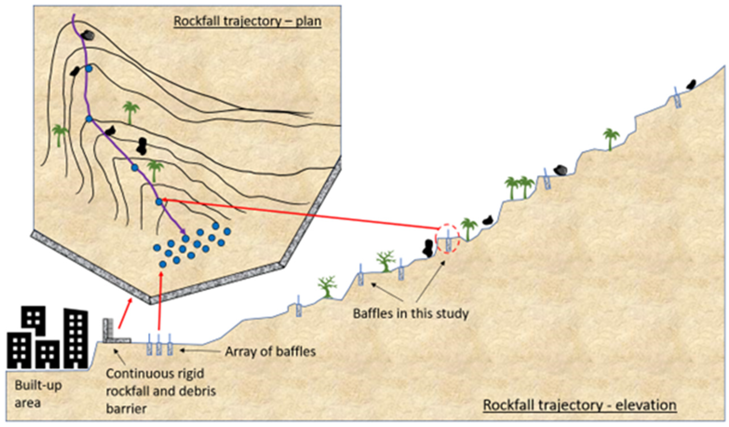
To fill this gap, the design of steel pole structures with a concrete encasement that can be easily constructed in a rockfall trajectory with a simple calculation procedure based on fundamental geotechnical and structural analysis is proposed by the authors [
34]. The suggested design involves steel hollow sections embedded in the soil layer and supported by a concrete cover, and can be placed in any location, even without access to a heavy vehicle. Some researchers have studied the use of multiple rigid barriers along the slope [
35]. Alternatively, construction of steel baffles in catchment areas near unstable rocks in multiple levels is a more economical use case to filter out some boulders along the slope and away from the rigid barrier designed for debris flows (as shown diagrammatically in
Figure 1).
In a previously published article, details of investigations into the geo-mechanical and structural mechanical behavior of baffles when impacted by fallen or flying object using small-scale experimentation are presented [
34]. In the current study, a new easy-to-use graphical-based design method utilising design charts for supporting the design of the steel baffles for providing protection of as-built facilities exposed to rockfall hazards are introduced. A sensitivity analysis has been performed with the aim of reducing the number of modelling parameters. The new design methodology serves the purpose of optimising the selection of baffles based on a prescribed impact scenario. The introduced methodology only considers the use of a single baffle to fence off fallen boulders. The use of two or more baffles at each level (connected with a high-strength steel wire) is preferable and is not within the scope of this study. Section two of this paper begins with a summary of the design philosophy, followed by a presentation of some condensed formulas from a previous publication. A sensitivity analysis on several parameters, including concrete encasement thickness, soil properties, section size, and embedment depth, is then presented. The design procedure is introduced in a stepwise manner, based on the design charts developed through the sensitivity analysis. Section three of this paper provides details of the numerical modeling used to validate the design. In section four, validation of the design is discussed considering four different impact case scenarios. Finally, section five offers a conclusion of the study.
2. Design of the Baffle
The design methodology presented in this paper is based on analytical predictive relationships that had been developed by the authors [
34]. For completeness, a summary of the design methodology, along with the background of development, is presented.
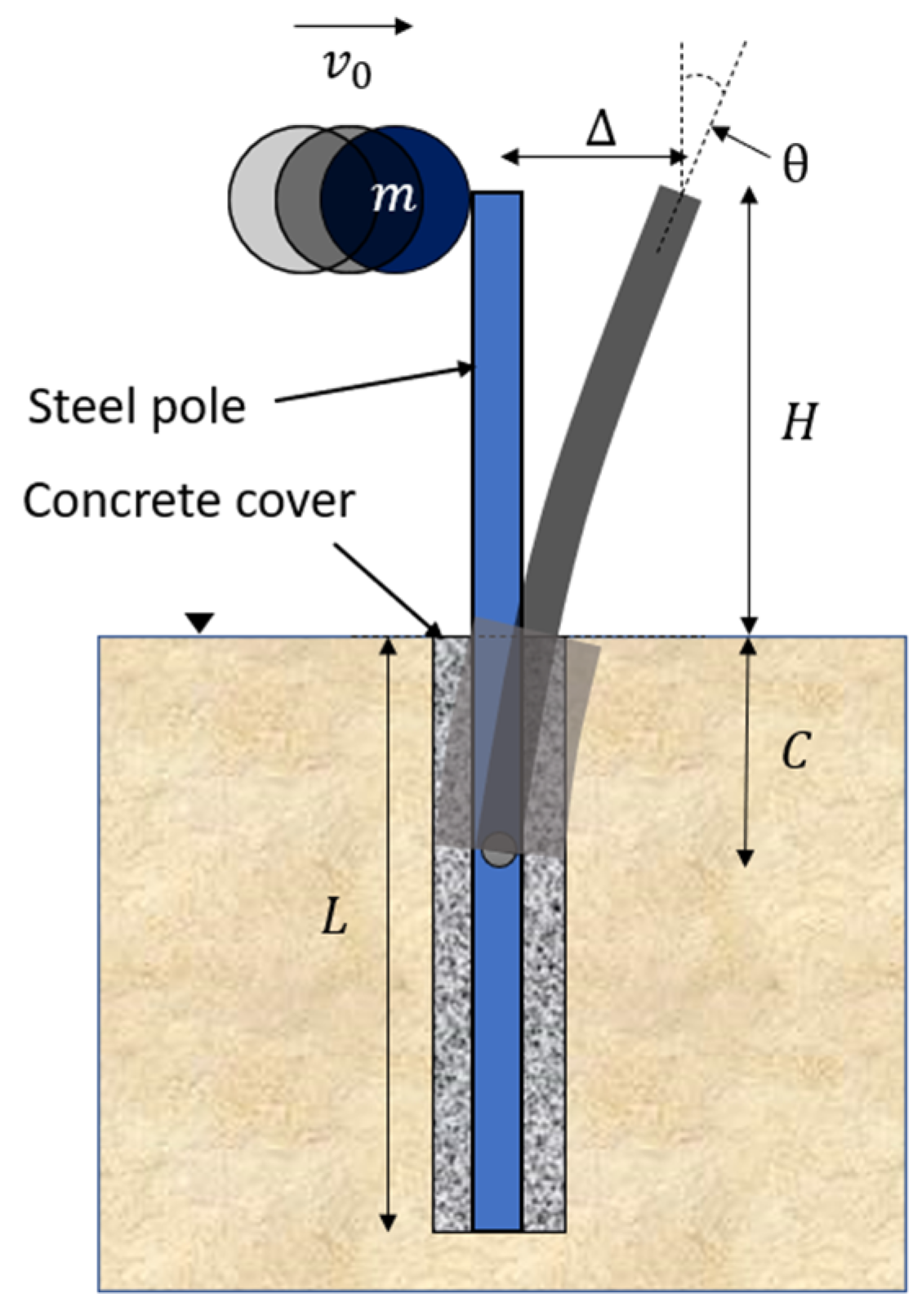
Consider a baffle (a pole) of a square hollow steel section that is embedded into the ground with a concrete encasement. The depth of the embedment of the baffle, which is denoted as ‘
L’, is to be designed to be adequate to withstand the projected impact. The baffle itself is allowed to have surpassed the limit of yield and allowed to undergo plastic deformation. Meanwhile, the base of the baffle is essentially undeformed, and the surrounding soil remains intact. The height ‘
H’ is designed based on the functionality requirement to contain fallen boulders. Length ‘
C’, as defined in
Figure 2, is at a depth to the point of virtual fixity above which deformation of the baffle occurs. Both the dimensions ‘
L’ and ‘
C’ are functions of ‘
T’, which is defined by Equation (1). Parameter
refers to the product of the Young’s modulus and the second moment of area of the baffle (
). The denominator
is the coefficient of the subgrade modulus of the soil that the baffle is embedded into.
Once ‘
C’ is known, the required stiffness of the baffle can be calculated by the use of Equation (2). The deflection and rotation at the top of the baffle in a project rockfall scenario can be calculated by use of Equations (3) and (4), respectively. The derivation of these predictive relationships can be found in [
34]. The design is based on the assumption that the fallen boulder strikes the baffle in a direction that is normal to the axis of the baffle, as this direction of impact is expected to generate the most onerous internal shear forces and bending moments within the member that has been struck.
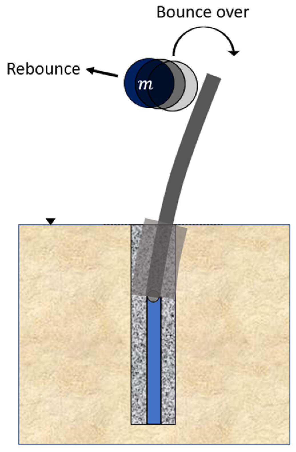
A baffle that has been designed to allow for plastic deformation to occur has a wide range of ductility. Should the deflection of the baffle exceed a certain limit when impacted, the boulder can go over the baffle, as shown in
Figure 3. An important design criterion is to limit the deflection of the baffle in order to ensure rebounding of the boulder on impact. According to experimental studies (along with follow-up numerical simulations) conducted by the authors, the slope of deflection at the top of the baffle must be kept within 10° to ensure rebounding [
34]. Sensitivity studies have been conducted to evaluate the optimal value of the concrete grout thickness, properties of the steel section, and the embedment depth for the given soil properties. The output from these studies is a recommended design procedure complete with design charts for designing a baffle to counter the projected impact scenario.
2.1. Grout Thickness
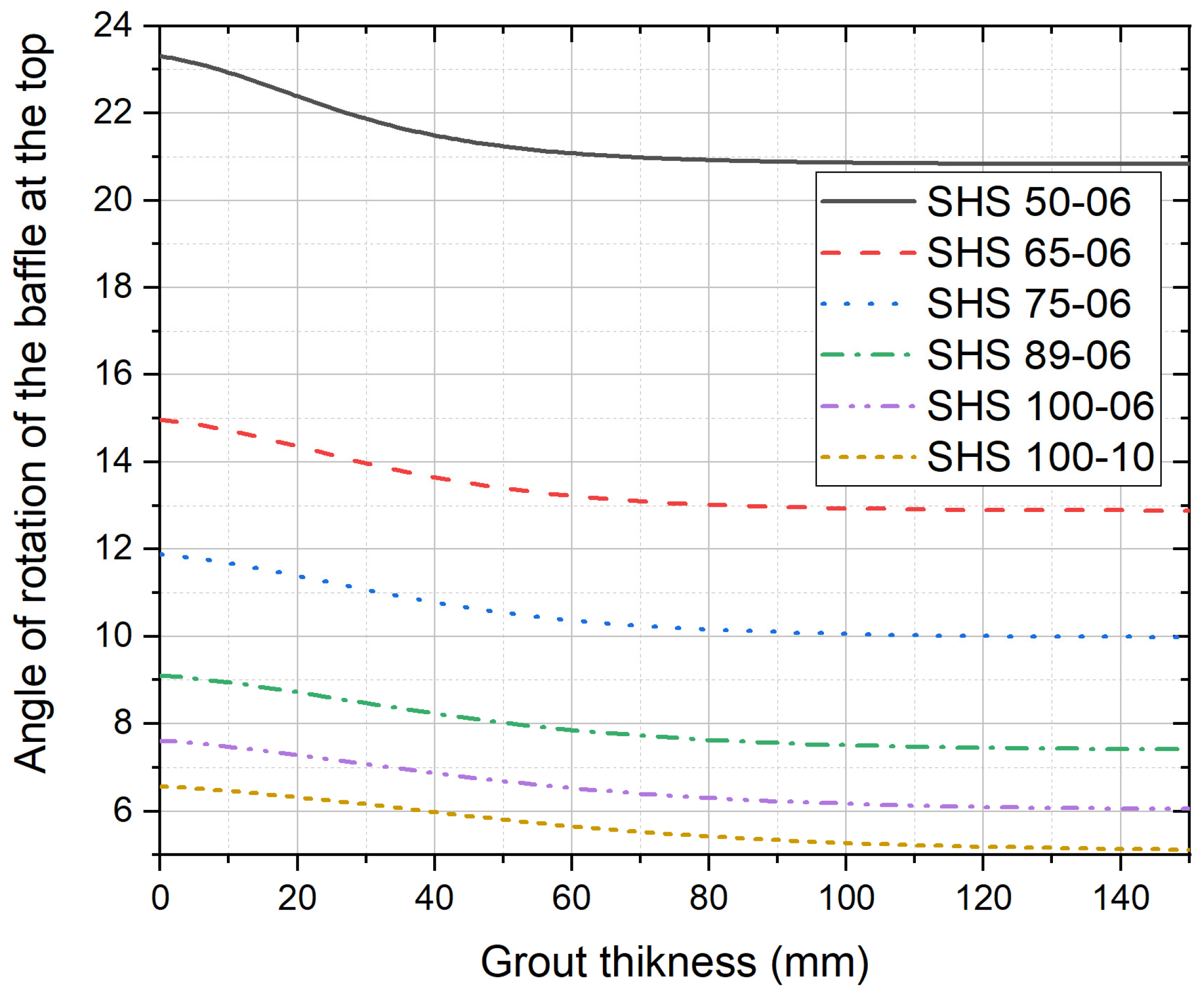
To safeguard the baffle from environmental degradation, there is a concrete grout cover surrounding the buried segment of the baffle. This concrete cover needs to be optimised in order to avoid being excessive, or else the baffle can be made undesirably stiff (which can result in a non-ductile failure mechanism). The sensitivity analysis was conducted for a 100 kg rock impacting at 10 m/s (5 kJ). Six different steel hollow sections have been analysed. The correlation of the grout thickness against the maximum slope of deflection at the top of the baffle is shown in
Figure 4. Note that SHS refers to square hollow sections, and the first two to three digits of the section identification number refer to the section size in mm, whereas the last two digits refer to the thickness of the section in mm. It should also be noted that should the thickness of the grout layer exceed 80–100 mm, the deflection of the baffle can become insensitive to a change in the thickness. Thus, the cover’s main purpose is to provide protection from corrosive elements that are present in the soil. The cover thickness is recommended to be in the range of 50 mm to 150 mm, with 100 mm being ideal.
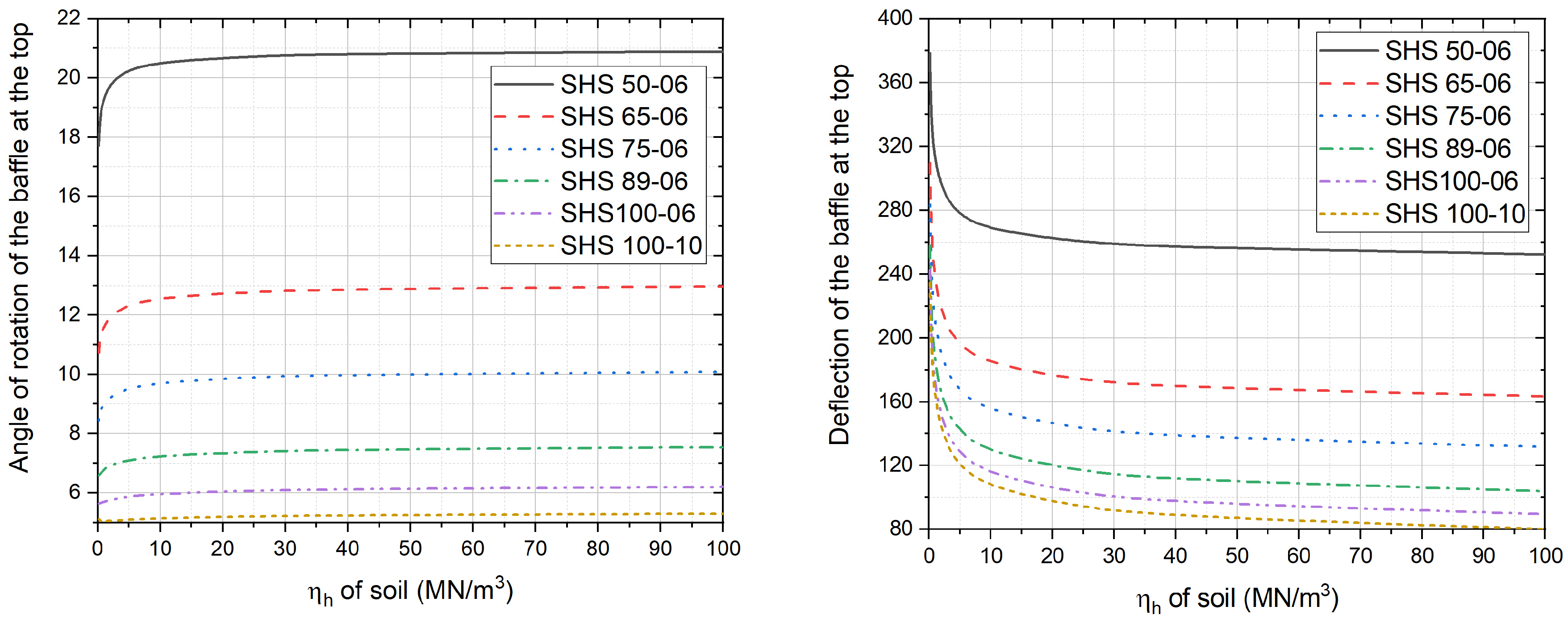
2.2. Soil Properties
Baffles can be installed in a wide diversity of soil types and conditions. It is recommended that the embedment be designed to avoid short pile behaviour, as the performance of a short pile design is difficult to predict. The depth of embedment should be adequate to ensure that failure occurs in the baffle, and not in the soil. The potential behaviour of the soil in the context of the embedment requirement is characterised by the parameter
. Softer soil requires a deeper embedment depth. Conversely, harder (stiffer) soil requires a shallower embedment depth. With softer soil, the depth to the point of virtual fixity ‘
C’ is larger. The equations presented earlier do not have any parameters representing properties of the soil. There is no need to have such a parameter, as the design is based on the assumption of adequate depth of embedment, which automatically creates long (flexible) pile behaviour. In other words, once the depth of embedment is sufficiently large, flexible baffle behaviour can be ensured irrespective of the soil properties and condition of the impact. A sensitivity analysis of the effects of the soil properties has been conducted. The findings presented in
Figure 5 reveal the insensitivity of the performance of the baffle to changes in the properties of the soil. The influence of the soil properties is not significant in conditions where
ηh > 20 MN/m
3. Interestingly, as the value of
ηh < 20 MN/m
3, the slope of deflection at the top of the baffle is actually reduced (hence providing better containment). Softer soil (with
ηh < 20 MN/m
3) can result in higher deflection at the top of the baffle and increase in the value of
C. With very soft soil (
ηh < 2 MN/m
3, massive embedment depths of 8–9 m may be required. In summary, the soil type has relatively minor bearing on the design of the baffle as long as the embedment depth is sufficiently adequate to result in a long pile design.
2.3. Selection of the Steel Section
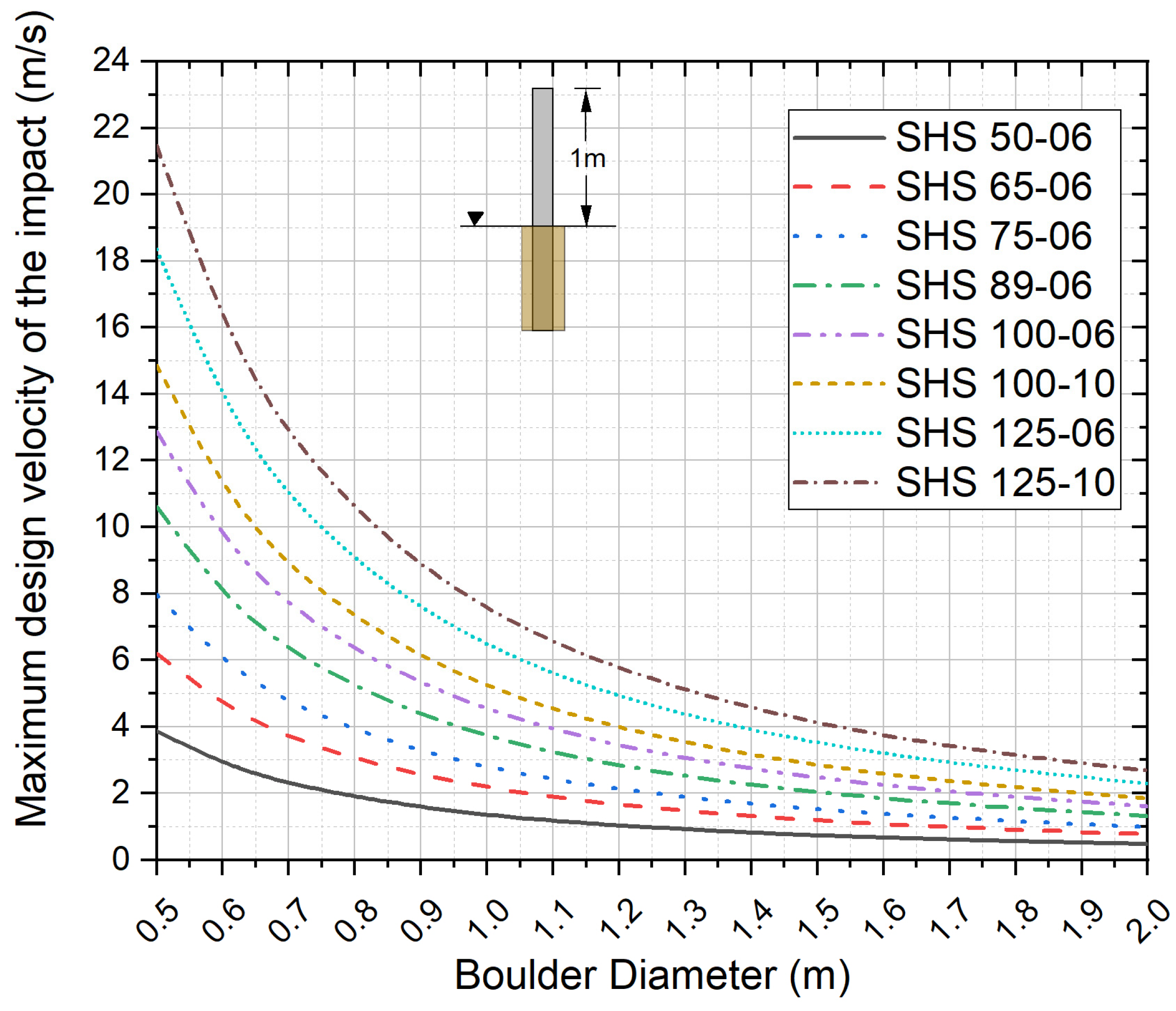
Sensitivity analyses reveal little influence of the soil type and grout thickness on the design parameter. A grout thickness of 100 mm was found to be reasonable. The two other design parameters are the steel section properties and height of the point of contact measured above ground.
Therefore, by keeping one parameter constant, a design chart can be developed to select the steel section for the impact design. In this regard, the height above the ground is kept as 1 m and the steel section was maintained at the minimum depth of embedment to have flexible baffle behaviour. By using
Figure 6 as a design chart, based on the average diameter of the boulders present in the area and the impact velocity based on the location of the placement of the baffle, a steel section can be selected from the design chart. For example, if a 0.9 m diameter rock is present at the rock falling trajectory and the maximum design velocity of the baffle is selected as 6 m/s, assuming the rock travels a vertical distance of 1.8 m before impact at the baffle, a steel section of 100 mm × 100 mm × 10 mm would be required to stop the boulder successfully.
2.4. Effect of the Height of the Section above the Ground
It is obvious that as the height increases, the critical impact location increases, resulting in a higher moment of impact in the structure. In situations where the rock has a diameter larger than 2 m and bounces from the ground level before the impact, situations can develop where the height of the baffle needs to be more than 1 m. To achieve this, using 1 m as the base case, a sensitivity analysis has been performed. The change of design velocity with the change of height aboveground is calculated and graphically presented in
Figure 7. Any value obtained from
Figure 6 above (1 m base case) can then be multiplied and adjusted if the aboveground height of the baffle needs to be changed or vice versa. Note that the buckling of the section that can occur with a taller section is not included in this study. It should also be noted that this factor is independent of the soil type and section properties, as well as the impactor diameter.
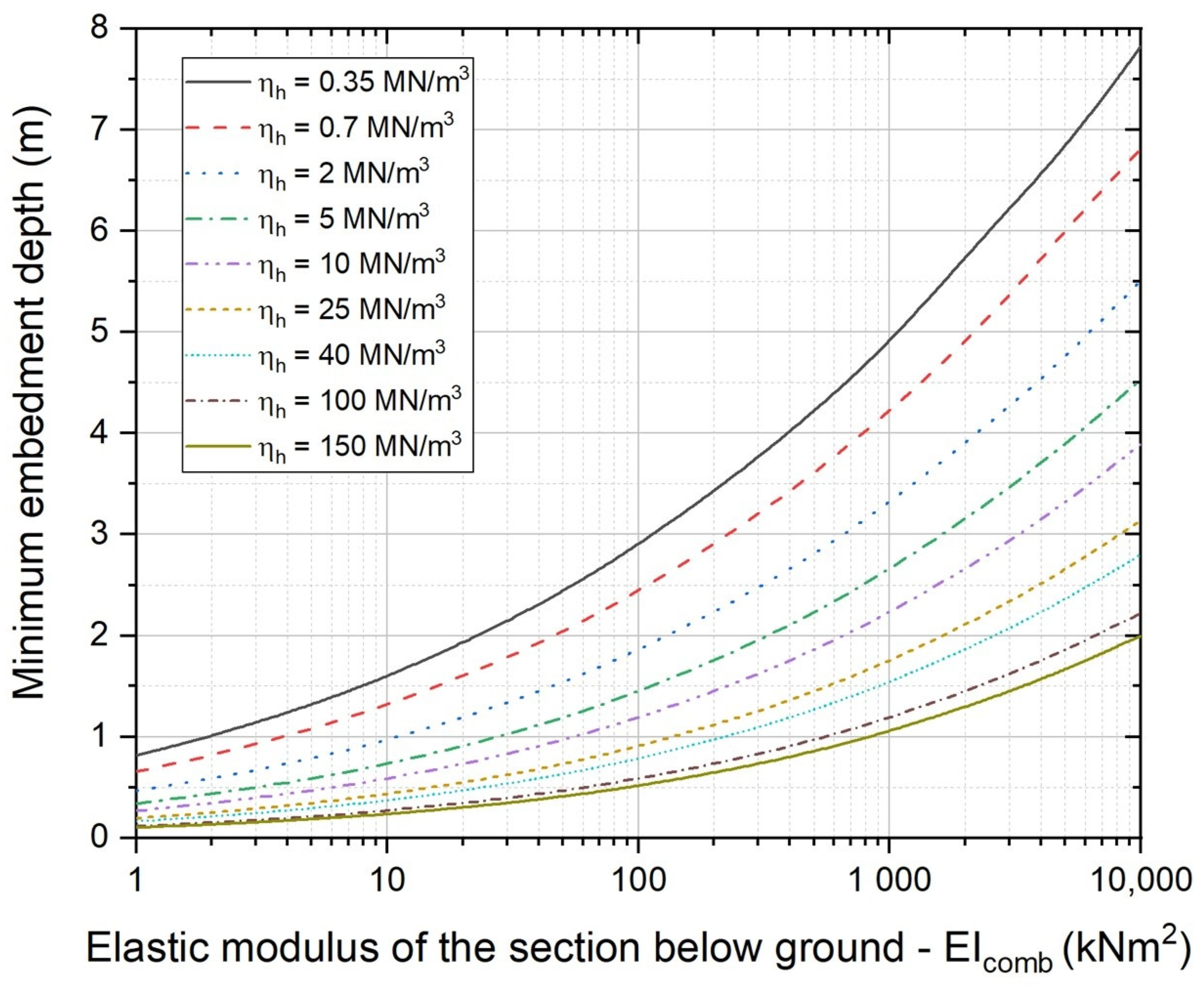
2.5. Embedment Depth of the Selected Baffle
For a given section type of the baffle, concrete cover thickness, soil conditions of the site, and impact scenario (as defined by the boulder diameter and impact velocity), the required depth of embedment must be fulfilled to ensure a safe and reliable design. Through sensitivity analysis on different soil properties, the design chart of
Figure 8 has been developed to facilitate determination of the required embedment depth for the selected baffle design.
The procedure for designing a baffle to counter a projected impact scenario (that can be estimated for a selected rockfall trajectory) is summarised as follows.
3. Numerical Modelling
The purpose of conducting numerical simulations is to verify the accuracy of the predictions by the design charts presented in the previous sections and to use case studies to illustrate their utility in the design of a soil-embedded steel baffle. The program LS-Dyna was employed for the numerical simulations. The accuracy of the simulations presented in this section have been previously validated by comparison against experimental measurements taken by the authors [
34].
3.1. Model Domain
The diameter of the impactor was selected as 1 m, whereas its density was taken as 2000 kg/m3. A mesh sensitivity analysis was performed to select the optimum size of the elements. Rigid boundaries were specified to save computational memory and time. In the numerical model, the distance of the baffle to the boundary was taken as 1.8 times the amount of deflection as the rule of thumb. Automatic surface-to-surface contact was specified at the contact interface between the impactor and the steel baffle. A higher frictional value of 0.9 at the interface was specified to control the level of noise that can be generated from the impact action at the point of contact. The impactor was selected as the “master” surface, whereas the baffle was specified as the “slave” surface. A “tied” surface-to-surface contact was specified at the interface between the steel baffle and the concrete grout (also known as the concrete cover). The grout was specified as the “master” side of the contact. An “automatic” surface-to-surface contact was specified at the interface between the surface of the concrete and the soil. The concrete (grout) was specified as the master side of the contact. A static and dynamic friction value of 0.8 between the concrete and the soil surface was specified. This frictional parameter value is higher than the usually assumed value of 0.6 for an interface between the soil (a mixture of gravel, sand, and clay) and a driven smooth steel pile. The segment-based contact algorithm (SOFT 2) is preferred when the stiffness of one contact element is much higher than the other. This contact algorithm serves the purpose of checking for segments versus segments (as opposed to nodes versus segments) penetration that are used in a default penalty contact formulation. It was noted from trial modelling that the segment-based contact model was not necessary in this instance because the steel baffle was tied to the concrete surface.
The steel baffle section was modelled using square shell elements, which were refined to a mesh size of 5 mm-by-5 mm. The impactor, the concrete (grout), and the soil backfill were modelled as solid elements.
For each analysis, the hourglass energy was monitored and compared to the internal energy. Type 4 stiffness form (Flanagan–Belytschko) with a default hourglass coefficient (QH = 0.1) was specified. Element formulation option 16 (fully integrated shell element) was used to define the steel baffle section. The wall thickness of the baffle was set to the exact thickness used in the experiment. All the solid elements were modelled using the default element formulation option ‘constant stress solid element’.
3.2. Material Models
This section provides a listing of the parameters for defining the material properties of the soil backfill, the steel baffle, the concrete grout, and the boulder. The soil materials surrounding the baffle are primarily classified in terms of their particle-size distribution depending on the relative proportions of clay, silt, and sand occurring in the solid phase. To obtain reliable results from the analyses, suitable material models were considered. Different material models that are available in LS-DYNA for modelling the soil are namely: the soil and foam (material number 5), soil and foam with failure (material number 14), Mohr–Coulomb (material number 173), Drucker–Prager (material number 193), and FHWA (material number 147). These soil material models were selected and evaluated. In view of the performance observed from the trial simulations when different material models were used, the FHWA material model was proven to be most stable when subjected to the desired amount of deformation that was expected.
The review involved making reference to the FHWA material model manual [
36] and the validation of the model with experimental results [
37]. The FHWA soil model was found to be effective in capturing damage evolution, strain softening, pore water pressure effects, strain rate effects, and moisture content effects. The FHWA material model has numerous parameters, some of which cannot be determined from experiments, therefore default values from the manual were used. This material model is frequently cited in the literature when presenting studies that are concerned with modelling highway guardrail posts and their interactions with the surrounding soil materials [
38,
39]. Twelve main input parameters used in the FHWA soil model are shown in
Table A1 in
Appendix A.
A plastic kinematic material model was specified with the shell elements for modelling the steel baffle. The elastic modulus of 200 GPa, Poisson’s ratio of 0.25, and yield strength of 350 MPa were selected. Details of these parameters can be found in
Table A2 in
Appendix A. The Winfrith concrete material model was used for representing materials used for casting the concrete jacket. The ultimate compressive strength of 20 MPa was specified for concrete, as in most cases, these baffles are to be constructed in areas that can be difficult to access. The tangential elastic modulus of 30 GPa, Poisson’s ratio of 0.22, and ultimate tensile strength of 0.3 MPa have also been specified. More details of these parameters can be found in
Table A3 of
Appendix A. The rigid material model was used to represent the impactor. An elastic modulus value of 40 GPa was assumed. The density of the rock boulder was specified as 2000 kg/m
3.
4. Validation of the Proposed Design of a Baffle
In this section, a case study is presented as part of a design example. LS-Dyna simulations are first used to validate the design example and then used for comparing and analysing alternative cases, which further demonstrate the robustness of the presented numerical model.
Design example: “A geological inspection of a rockfall trajectory reveals that the largest available rock in the area is around 1 m in diameter. Falling rocks following the trajectory during a rockfall event can reach a velocity of 6 m/s (or 21.6 kmph). The soil available in the rockfall trajectory has been identified as dense sand with = 25 MN/m3. A system of baffles is to be designed to provide containment of the fallen rocks”.
The calculation of this design example adopting the proposed methodology is summarised as follows:
To validate the model with respect to the design example, four case studies were selected, as listed in
Table 1.
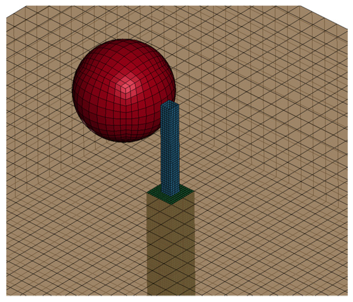
Figure 9 illustrates the 3D view of the numerical model. Only a 2D view of the model is used in the rest of the paper for ease of visualisation. The maximum principal stress of the elements of the baffle, as well as the movement of the centre of gravity of the boulder, are also presented for a reference in each case.
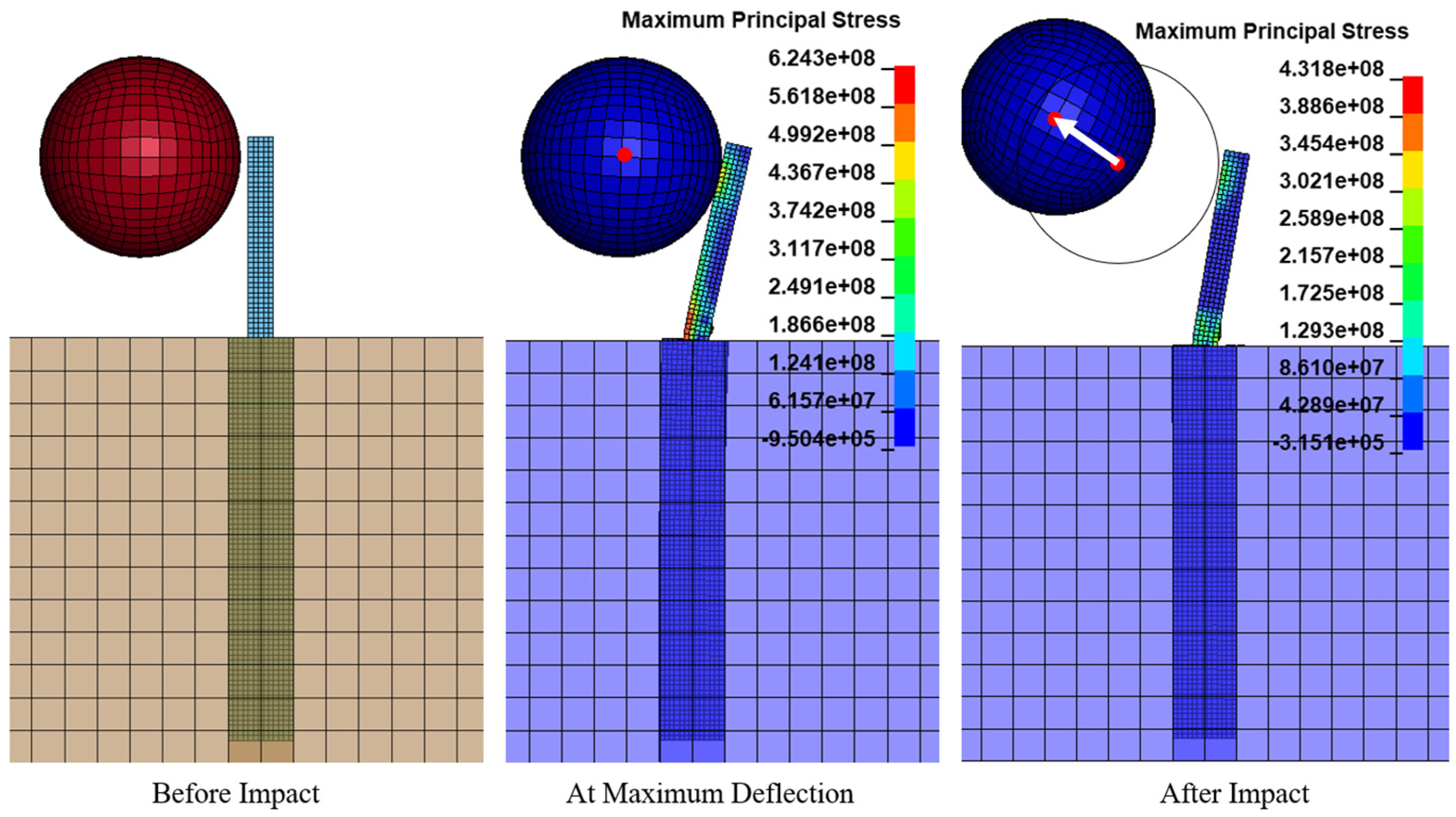
The numerical results of the design example (
Figure 10) show that the selected baffle design based on the use of the design charts is able to perform satisfactorily in terms of providing containment of the fallen boulder with the projected impact scenario.
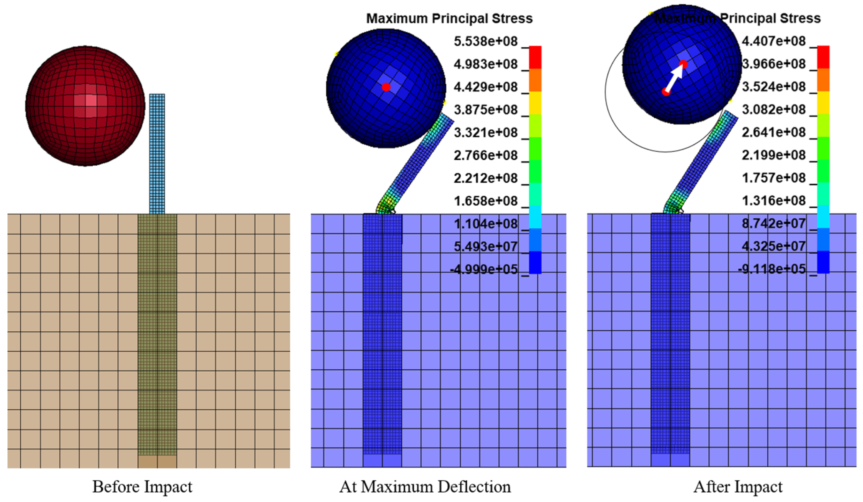
As is evident in
Figure 11, when the impact velocity is below the design value (case 1), the boulder bounces back whilst causing minor damage to the baffle.
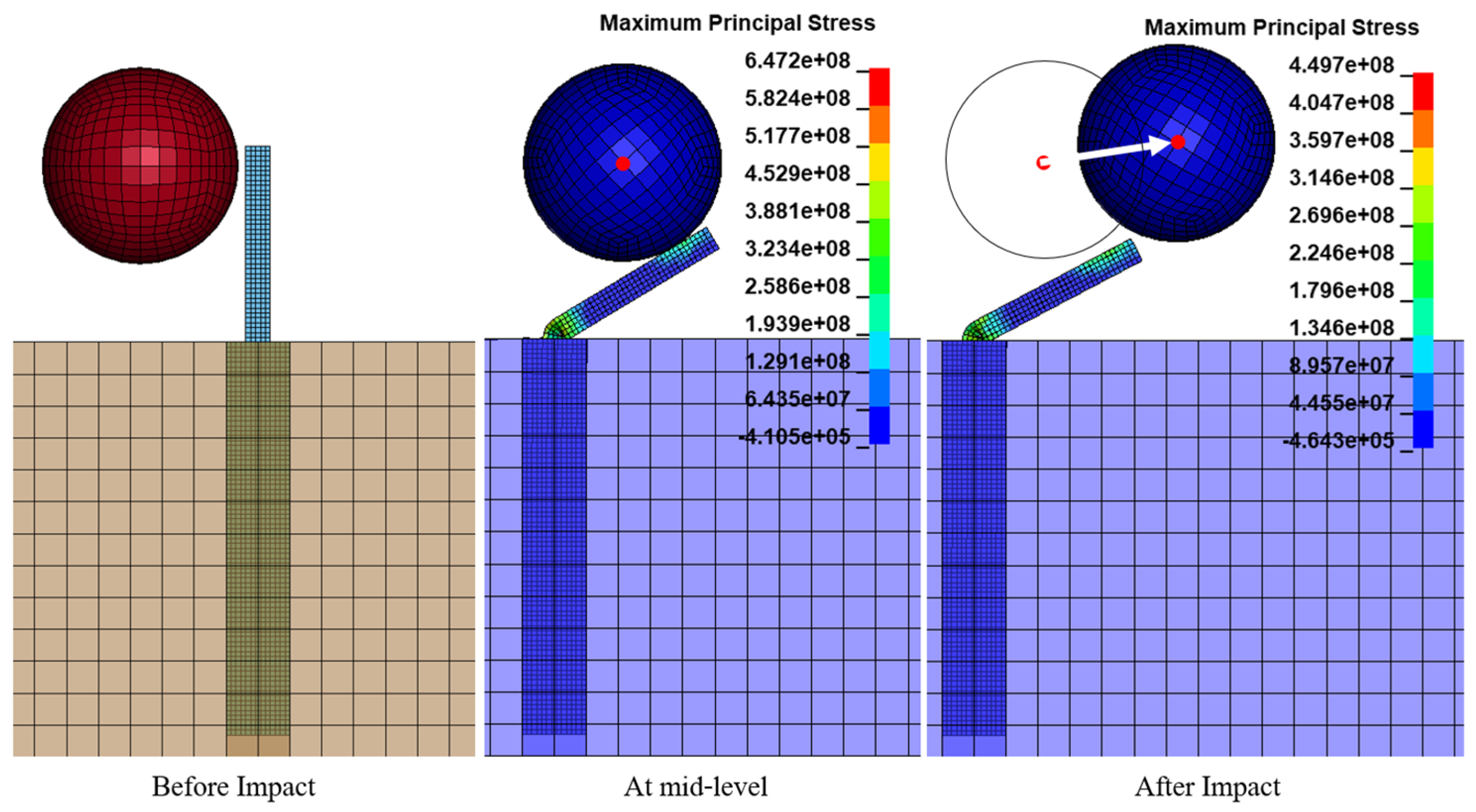
To validate the model, a velocity exceeding the design velocity must be used. This is tested in Case 2 by increasing the boulder velocity to 8 m/s.
Figure 12 depicts the findings from this case study. As the impact velocity surpassed 8 m/s (without changing the baffle design), the baffle became incapable of containing the boulder, causing it to topple over. Hence, the baffle design parameters chosen were the best parameters for the design velocity (6 m/s).
To further prove this, in Case 3, the impact velocity was increased to 10 m/s without changing any other details of the baffle. It can be seen from the
Figure 13 that the baffle was totally destroyed as the impact velocity was increased to 10 m/s.
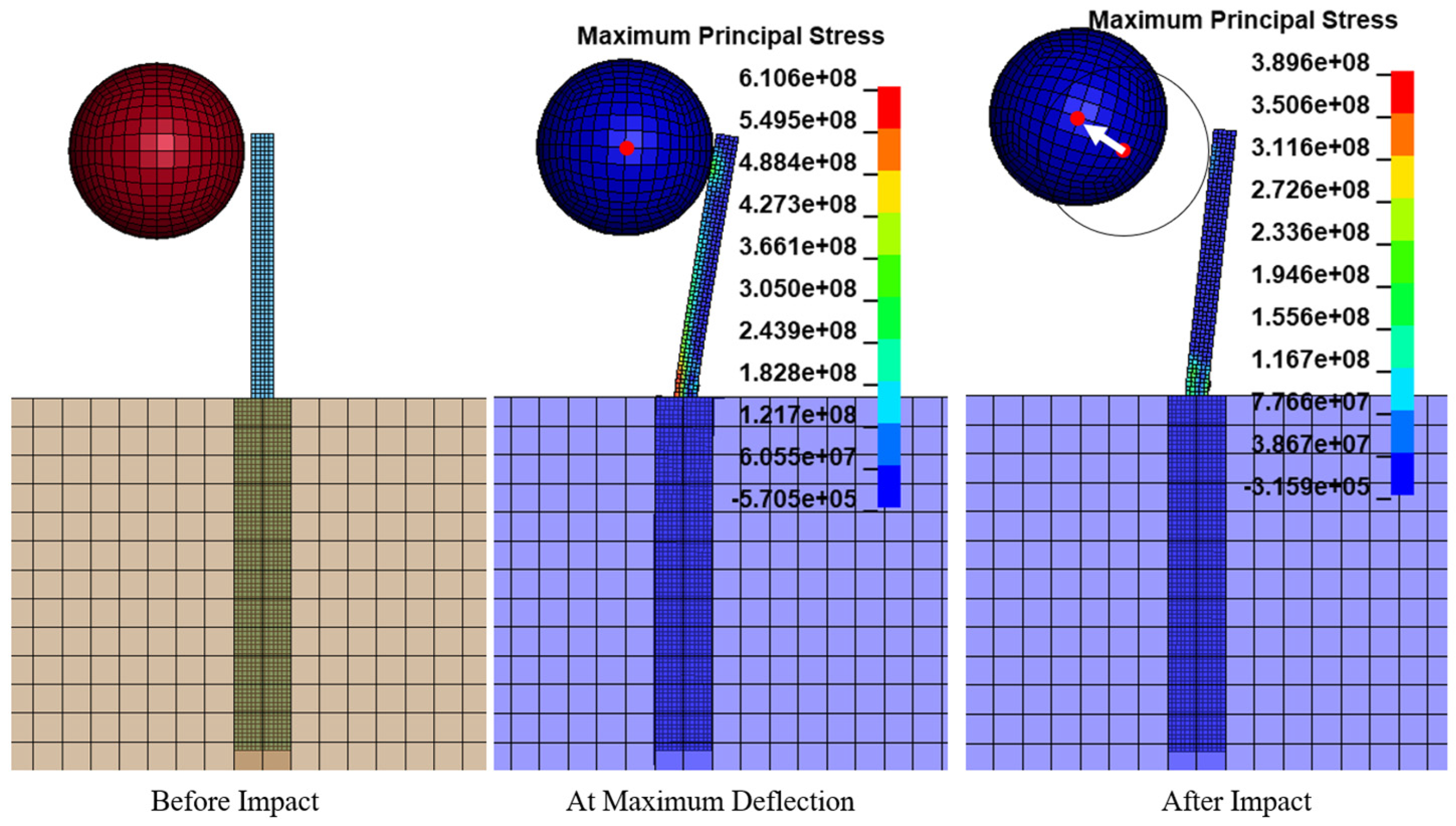
Another case study was conducted to evaluate the validity of the design chart shown in
Figure 7 with the baffle height above ground changed to 1.5 m. According to
Figure 7, for a baffle height of 1.5 m, the design velocity must be reduced by 0.8. For a baffle height of 1.5 m, the same boulder impacting at 4.8 m/s (0.8 × 6 m/s) should be safely contained by the baffle. This expected performance of the baffle was tested in the LS-DYNA simulation, as shown in
Figure 14. Should the design parameters be modified in accordance with
Figure 7, the baffle can be safely designed for heights other than 1 m above ground and should give closer results to the base case of 1 m.
The amount of displacement at the upper end of the baffle has been analyzed using numerical simulations (
Figure 15). The displacement parameter can be used to indicate the degree of damage caused to the baffle for a projected impact scenario in elastic, or plastic, conditions. The findings reveal that, in the design example, in Case 1 and Case 4 the baffles exhibited a degree of elastic recovery at the conclusion of the impact event, indicating that complete structural failure did not occur. A similar amount of total deflection is predicted for both the design example (baffle height above ground = 1 m) and Case 4 (baffle height above ground = 1.5 m), providing further evidence of the effectiveness of the proposed graphical design methodology in terms of achieving an optimal baffle design for any given rockfall impact scenario.
Figure 16 illustrates the velocity profile of the impactor, with positive values indicating the movement of the impactor (from left to right) prior to the occurrence of the first contact, whereas a negative value indicates rebound of the impactor (from right to left). The results show that rebound would occur in the design example, Case 1 and Case 4. Therefore, the selected baffle can withstand an impactor velocity of up to 6 m/s (design velocity) but is unable to contain an impactor cruising at a velocity of 8 m/s or 10 m/s.


