

Evaluating the Effect of Overburden Depth, Mining Height, and Support Density on Coal Rib Damage Using DEM Modeling


Department of Mining and Explosives Engineering, Missouri University of Science and Technology, Rolla, MO 65409, USA
*
Author to whom correspondence should be addressed.
Geosciences 2023, 13(3), 77; https://doi.org/10.3390/geosciences13030077
Submission received: 2 January 2023
/
Revised: 5 March 2023
/
Accepted: 7 March 2023
/
Published: 8 March 2023
(This article belongs to the Collection New Advances in Geotechnical Engineering)
Abstract
:There has been a global effort in the past decade, especially in major coal-producing countries, toward understanding the mechanics involved in the stability of coal mine ribs. Buckling and spalling of mine ribs are known to have an impact on their stability and degradation. The generation, propagation, and coalescence of cracks in mine pillar ribs are significantly affected by the overburden depths. In addition, the in situ stress magnitudes tend to affect the rib damage process. High horizontal stresses and increased depths can lead to unfavorable stress conditions, inducing coal mass damage and strength loss. Understanding the dynamics involved in rib behavior will inform better rib control practices. This study intended to assess the effect of mining depth, mining height, and supports on coal mine rib stability. In this research, the response of the coal mass was studied using distinct element modeling to better understand the failure process of coal mine ribs. The study confirmed mining depth as a significant factor controlling the rib loading and failure mechanism. In addition, increased mining heights increased the rib deformation and failure process. The evaluated support effect revealed that at shallower depths, shorter bolt lengths are sufficient to control rib stability. Increasing the bolt length for depths greater than 250 m is in order, but higher depths do not correlate with longer supports. The approach used in this study demonstrated its capacity to be used in designing rib support requirements and understanding coal mass and support mechanisms.
1. Introduction
Safety, productivity, and regulatory requirements are the factors that drive the need to keep all underground excavations stable and serviceable. There is a global effort by researchers to provide an understanding of the behavior of underground coal mine ribs to improve their stability. Most of these efforts started in the late-1980s. These previous research works provided great knowledge on rib support requirements and the selection of site-specific suitable supports. Nonetheless, the trend of rib-related fatalities in underground coal mines has remained steady in the past decade. It is true that there is an overall improvement in rib safety, but the average fatality rate is still about 1.4 per annum in the period between 2009 to 2021 [1]. Most rib-related fatalities reported in the United States occurred at overburden depths between 152.4 m and 304.8 m. Rib instabilities increase with depth, resulting from high in situ stresses and complicated geological conditions. In this case, the risk of underground safety, productivity, and economic benefits is pronounced. The major factor that affects the safety of deep underground openings is the high in situ stress resulting from overburden loading. Many serious problems may arise due to high in situ stresses such as large deformations and failure around the rib. Managing these issues is challenging even with the installation of a support system. A previous study of rib fatalities in underground coal mines by [2] found that 70% of rib fatalities resulted from stress-driven rib falls.
It has long been known that rib stability is strongly influenced by site-specific geological conditions and the mining layout. Therefore, it is essential to emphasize that field surveys of rib performance are necessary and irreplaceable for the rib design process, not discounting the fact that it is costly and time-consuming. Field survey data can present valuable information to evaluate performance, also for designing rib supports and helping engineers to better understand the rib behavior. These data, when interpreted correctly, can significantly contribute to rib support design improvements for future work. In this paper, a summary review is conducted on rib stability control around the world. In addition, a coal rib model is developed using the bonded block modeling approach and the performance of the rib is tested against varying overburden covers and mining heights. Additionally, the rib support is also evaluated to determine the appropriate geometry and density for a particular coal lithotype. The model is implemented in UDEC [3].
2. Literature Investigation of Rib Stability
The support and control of mine coal ribs are recognized and ongoing problems in the coal industry. There has been a systematic research investigation that started over 30 years ago in the Australian Coal Industries Research Laboratory (ACIRL) [4]. In the US, the National Institute for Occupational Safety and Health (NIOSH) is currently undertaking a comprehensive study into ribs with an end goal toward recommending appropriate support for its control [5,6,7,8]. This section of the paper critically reviews rib control and support studies around the world to reveal the challenges and opportunities in these works.
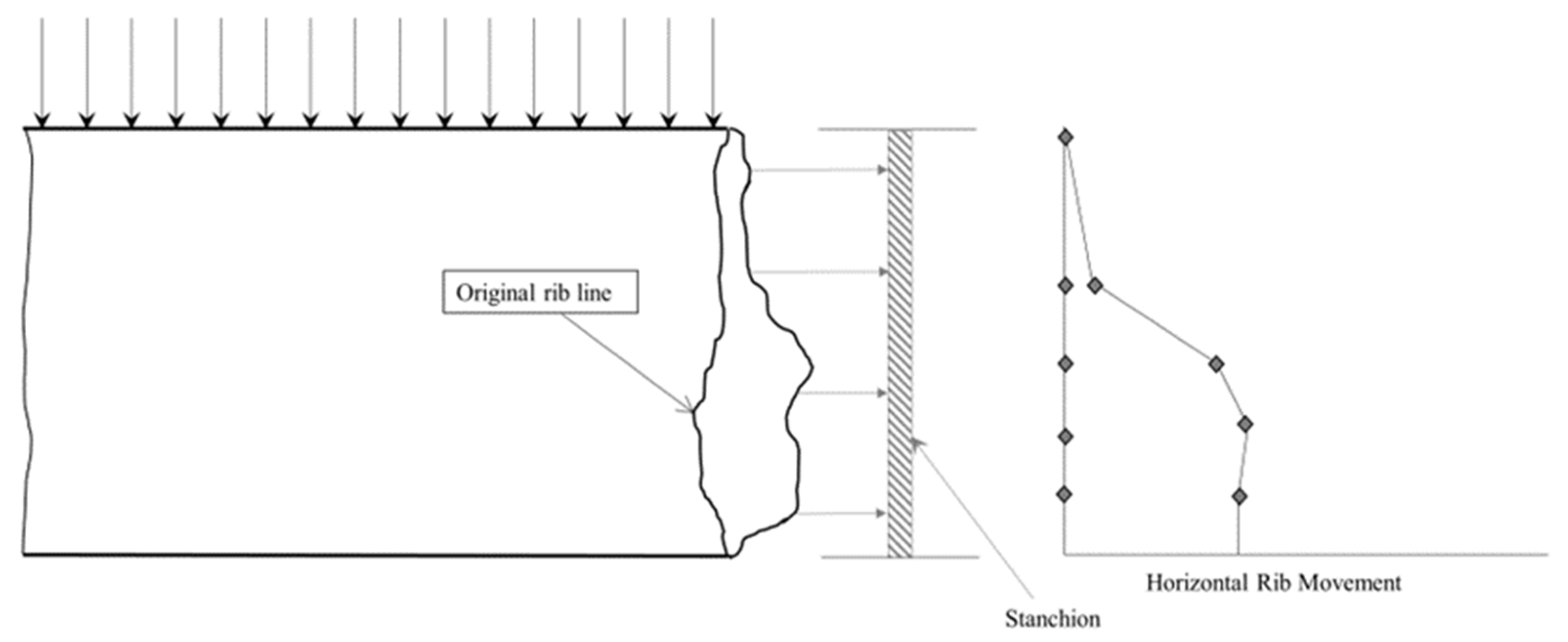
O’Beirne and Shepherd [9] investigated the stability of coal ribs at several Australian coal mines. They classified coal ribs according to a visual assessment of their condition and measured values of spall depth and visible fracturing. In this study, they used extensometers to measure rib deformations and the convergence of the roof to floor of the roadway. A novel method involving the installation of a vertical stanchion, offset to about 200 mm to 300 mm from the rib, was devised to record its movement. Figure 1 presents an idealized representation of the installation of the stanchion and how the data were analyzed in a data plot.
The study of O’Beirne [10] observed two distinct failure mechanisms, namely: (a) buckling of plates, slabs, or columns resulting from the convergence between the roof and floor over the ribside as a consequence of an increase in the vertical stress; (b) existing cleat and mining-induced fracture (MIF) interaction, which mostly activates granular and/or blocky spall.
In 1992, the US Bureau of Mines, some of whose functions NIOSH now performs, investigated methods to improve rib stability [11]. The goal was to improve the safety of miners. The investigations noted rib failures as not entirely avoidable, but the need for a practical approach to understanding, characterizing, and controlling rib conditions was necessary. Two basic rib failures were determined in this study: slabbing and brittle. The bureau researchers also demonstrated the important factor of the roof and floor constraint on the rib stability. Generally, a strong roof and floor rock enhances rib confinement pressures near the roof and floor and, thus, leads to a better rib performance, while a weak, ductile roof and floor rock reduces rib confinement pressures near the roof and floor, leading to a poor rib performance. This study observed that the foundation to appropriate rib support selection is understanding its mechanics. The study recognized numerical modeling as an advanced tool to model the complex-parameter interactions in ribs. They emphasized the importance of employing distinct element models when slabbing or brittle failures, two dominant rib failures, are expected. This supports the authors choice of distinct element modeling (DEM) as an appropriate method to investigate coal rib stability.
Fabjanczyk et al. [12] suggested that the behavior of the coal mine roadway ribs is heavily dependent on the magnitude of the vertical stress and the response of the coal to that stress. Fabjanczyk et al. [12] suggested that within a high-vertical-stress environment, the deformation of the rib is almost uniquely controlled by the nature of the coal and its capability to generate confinement. They viewed the function of rib support as a means to increase the residual strength of the coal mass. Conventionally, rib degradation is often discussed in terms of being displacement-driven, i.e., roof to floor convergence. In Fabjanczyk et al.’s [12] works, however, rib behavior and support effectiveness were discussed in terms of the vertical stress environment.
Based on a laminated strain-softening model developed by [13,14], Hebblewhite et al. [15] identified three potential regions within a coal pillar under load, namely, elastic, yield, and crush (Figure 2). Hebblewhite et al. [15] suggested that quantification of these failure zones provides guidance and direction to the type and length of the rib support under various loading regimes. The ability of the rib to provide vertical support to the roof would be reduced over the yield zone and negligible above the crushed zone. Therefore, control of the rib deformation and minimizing the extent of yield and crush zones are not only important to improve rib stability but also to reduce the potential domino effect negatively impacting the roof and floor stability. Hebblewhite et al. [15] also investigated the mechanics of coal rib behavior and identified important engineering parameters for potential rib reinforcement hardware. They identified the yielding characteristics of the immediate ribside and quantified them for several coal seams from extensometers and bolt load monitoring. The study investigated two extremes of rib behavior ranging from a very friable, weak coal to a stronger coal. The stronger coal behaved quite differently, and they recommended a high-strength, stiff-rib reinforcement anchored beyond the depth of the yield zone. It is possible that these two extreme cases will cover most seam behavior. In any of these extreme behaviors, the interaction between the rib and roof control must be recognized.
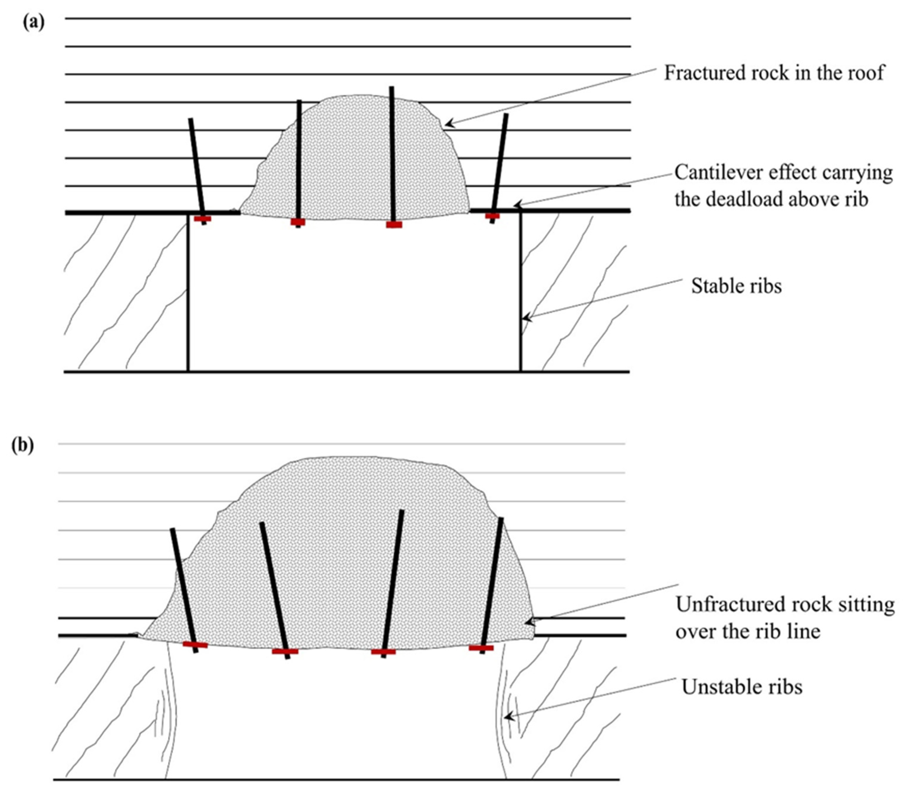
Frith and Ditton [16] used measurement, observation, and anecdotal evidence to understand the mechanisms driving rib failure. As a part of investigating the impact of the in situ stress regime on rib stability and, in particular, the ratio of horizontal to vertical stress, Frith and Ditton examined two cases: (a) a roadway subject to a high value of horizontal stress in relation to vertical stress, and (b) a roadway subject to a value of horizontal stress that is the same in magnitude to the vertical stress. In (a), the zone about the ribs actually de-stresses, whereas in (b), a vertical compression environment is induced in the ribs; Figure 3 illustrates these two scenarios. The findings in this study highlighted the fact that the magnitude of the horizontal stress structural competence of the immediate roof will determine the amount of deadweight generated for the rib to bear.
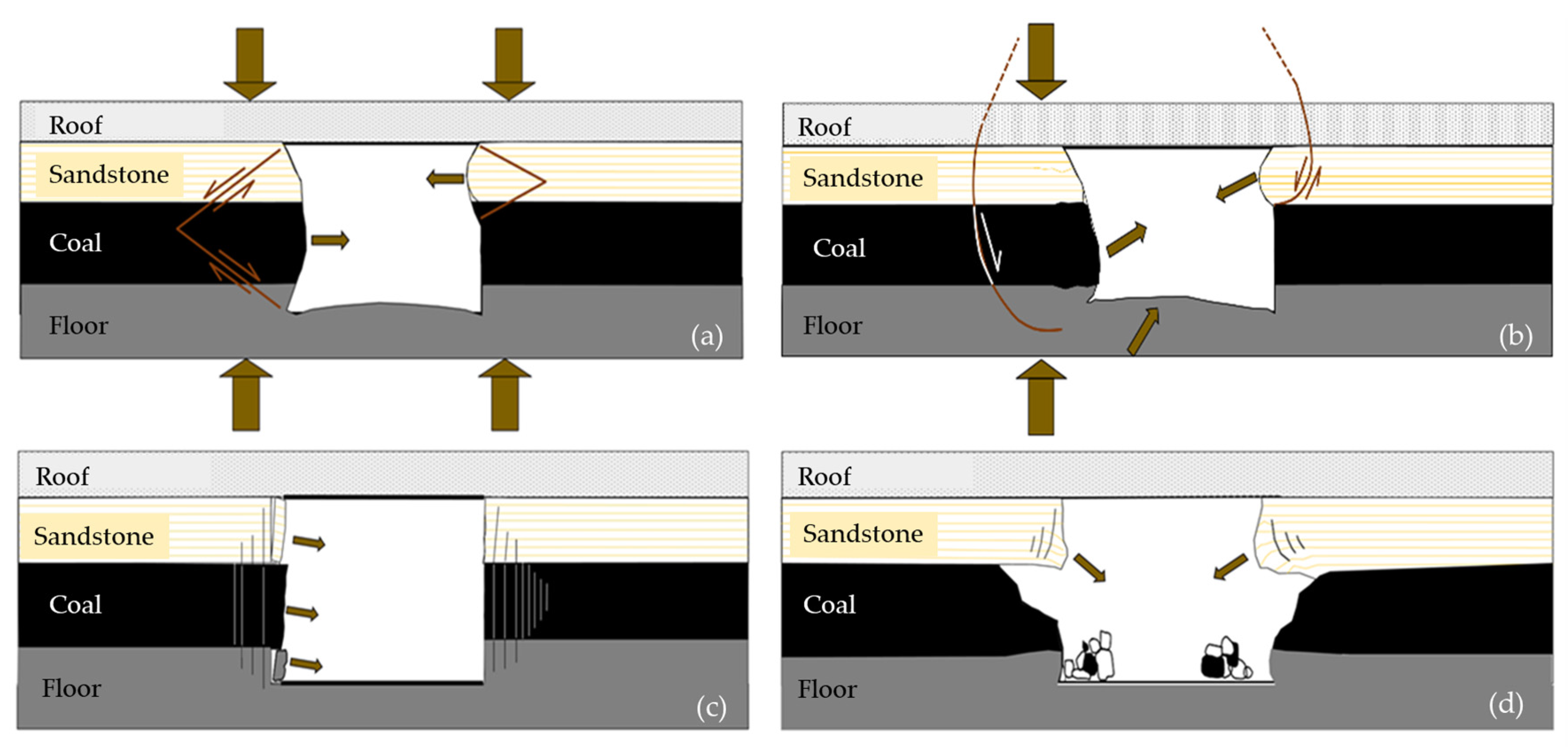
Kent and Bigby [17] investigated the risk of falls of the ground associated with rib failure and reinforcement mechanisms. Bigby and Cassie [18] identified four general rib failure characteristics in UK coal. These are illustrated in Figure 4 and are classified into compressive, shear, slabbing, and toppling. They stated that assessing the risk of rib falls should be tailored to match with the coal mass and excavation characteristics. A better tool to employ to help in understanding these mechanisms is numerical modeling. They also identified: (a) vertical stress distribution, (b) rib support load, (c) horizontal rib displacement, and (d) acoustic energy decay to be suitable in providing a quantitative measure of the stability of coal ribs.
Colwell [19,20] implemented a program of full-scale field trials at ten mines in Australia, and in conjunction with a comprehensive industry-wide review of ribline performance, formulated a database that was analyzed statistically. The results of this study and the knowledge learned of the mechanistic behavior of coal mine ribs resulted in the development of the Analysis and Design of Rib Support (ADRS) for the Australian underground coal mining industry.
Heritage [21] conducted a field measurement of rib deformation in addition to a field monitoring of rib bolt loads and rib yield characteristics using a range of measurement techniques. The investigation intended to assess the effectiveness of rib support patterns with consideration of the nature of the rib deformation using field measurement and numerical modeling. It was observed in this study that irrespective of the observed variation in mechanistic rib behavior, the rib support design applied is typically similar across different mines and for different seams with similar overburden depth. Results from the monitoring exercise suggest that rib support serves to minimize the progression of failure into the rib by controlling kinematic failure and generating confinement of the fractured and yielded rib.
Learning from the research in Australia, especially the works of Colwell [19,20], the rib research work currently ongoing in the US recognizes the difficulty in collecting the massive amount of data necessary to build the needed database for analyzing rib performance. As a result, they proposed a hybrid method involving the numerical modeling and experimental data collection approach for rib design. The challenge here is employing a realistic rib modeling approach that can be achieved through calibration and validation against field data. The NIOSH research to date has developed a logical procedure for a Coal Pillar Rib Rating (CPRR) to assess the integrity of coal ribs. For a given overburden depth, the rating system can be used to define the required support to be installed to control rib falls. The analysis for recommending these support designs is based on engineering stress models that have been evaluated and verified. Additionally, a user-friendly application called Design of Rib Support (DORS) was developed to be used in evaluating rib performance by calculating the CPRR, rib factor of safety, and rib category, and also for calculating the Primary Rib Support Density (PRSD) for unsupported coal ribs.
Many of the previous works were mostly field-based instrumentation and data collection. These data collection programs are expensive and time-consuming, and the nature of the operations and characteristics of the seam sometimes causes the instrumentation to malfunction. Rib monitoring using instrumentation can be prone to missing important actions taking place in the rib. For example, where extensometers are placed in sections of the rib predisposed to severe dilation, the results may not give a good indication of the global rib performance [19,20]. The importance of a field rib monitoring program is invaluable but supplementing these programs with computing should be the way forward. This is supported by some of the earlier studies that attempted to employ numerical modeling to understand rib behavior [7,11,18,21,22]. The design of rib support strategies should be science-based with a correct understanding of the mode of expected rib failure. This knowledge can be gained from local experience and data obtained from the measured ground control monitoring program and numerical modeling tools. Physical and numerical models can provide important information on rib behavior based on global and local parameter interactions not easily quantified in field measurements. The application of a support to control rib performance should be strategic and must involve an understanding of the problem rather than the ad hoc installation of supports when rib failure occurs. As a rule of thumb, supports should be installed at the earliest possible time while the rib still remains intact or before the development of severe fractures and lost frictional properties in these contacts. Rib monitoring techniques should be compatible with the types of rib failures expected.
3. Rib Spall Modeling
The failure mechanisms observed in the rib deformation process are often characterized by:
- Crushing and wedging of the rib into the roadway;
- The development of shear planes within the roof that extends down into the floor, causing the base of the rib to bulge into the excavation accompanied by floor heave;
- Blocky or slabby, which involves slabs or chunks of coal sloughing off the rib along a particular cleat or fracture surface;
- Toppling in the upper ribside when the lower rib becomes degraded, leading to the upper rib overhanging.
The fourth failure process is termed the rib with brow problem and is somewhat common in US coal mines. In all of these rib degradation processes, with the exception of (2), it is evident that there is splitting, slabbing, or blocky failures that are purely discontinuous. Therefore, a modeling tool capable of replicating these processes is more appropriate. The distinct element modeling (DEM) method is capable of modeling the evolution and distribution of fractures inside the rib and can predict potential areas of rib degradations. DEM was employed in this study using the Universal Distinct Element Code (UDEC) software.
3.1. Calibration of the Contact Parameters
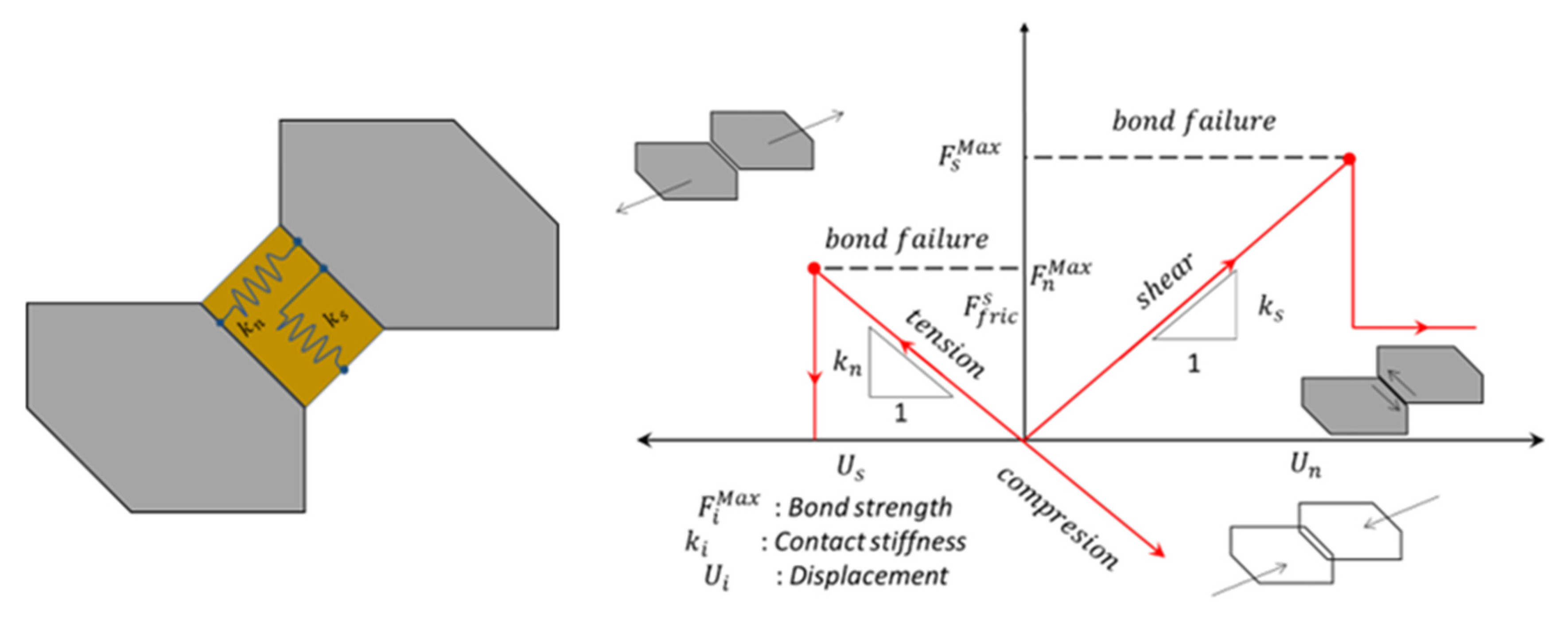
The rock and coal mass in this study were modeled using the Voronoi tessellation logic in UDEC to obtain the material parameters of the polygonal blocks and their contacts. Previous studies established that the macro-properties of the coal and rock materials are dependent on the contact micro-properties of the Voronoi blocks [23,24]. In this study, the grains were assigned linear elastic constitutive relations without ultimate strength, and the grain contacts were assigned the Coulomb slip joint model. Usually, a calibration protocol is implemented to calibrate these micro-parameters. Figure 5 illustrates the mechanical calculation principles of the Voronoi tessellation blocks. The Coulomb friction law governs the mechanical behavior of the contacts bounding the blocks. In this method, cracks initiate and grow along the boundaries of blocks when the maximum stress exceeds tensile or shear strength thresholds. This concept follows the following rules: ; ; is the change in normal stress, is the normal stiffness, is the normal displacement, is the change in shear stress, is the shear stiffness, is the incremental shear displacement, and C and are the cohesion and joint friction angle, respectively [3,25,26].
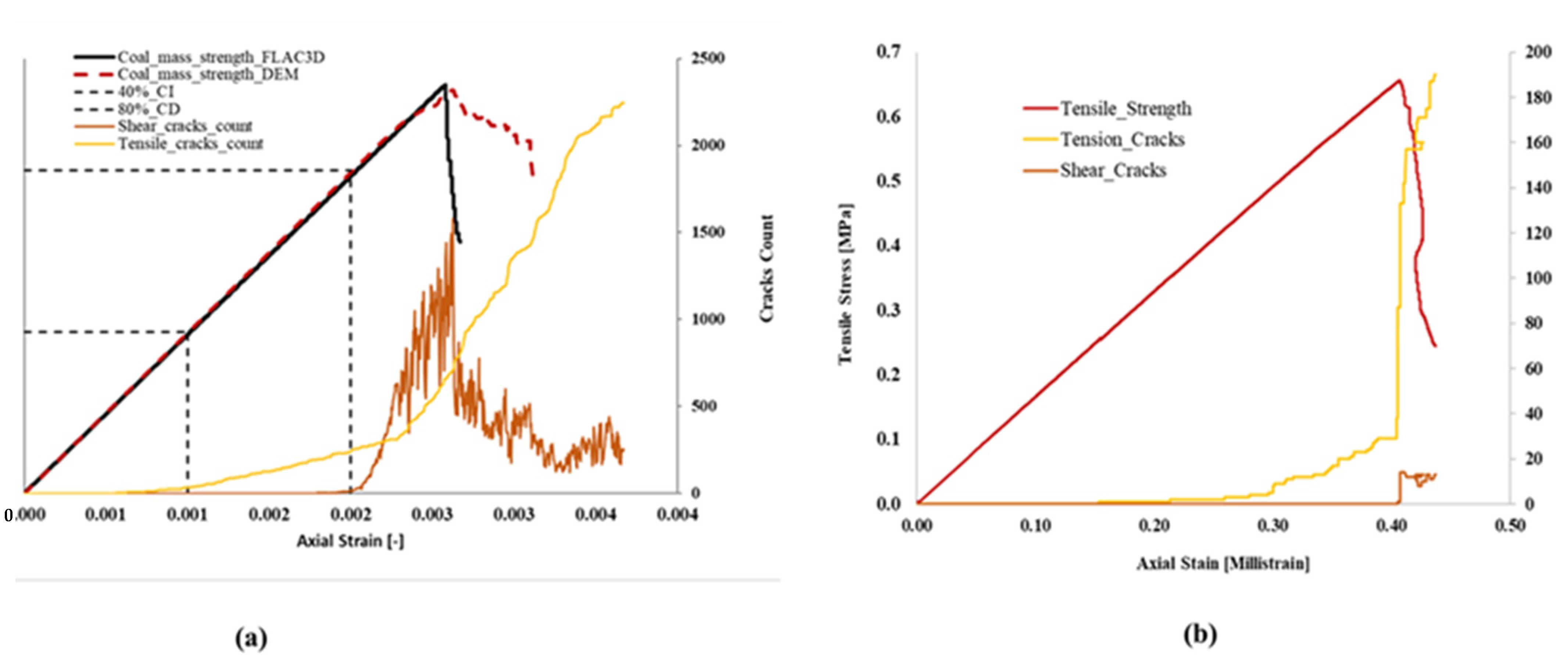
In a previous study by [22], a coal mass model was developed to model the loading and deformation characteristics of coal ribs. The model is capable of simulating the peak and post-peak behaviors of the coal material by using the strain-softening and ubiquitous joint models in FLAC3D. This coal material model has been calibrated to match in situ rib cases in the field and fully implemented in the FLAC3D program as a user-defined constitutive model. One novelty about the coal mass model is that it takes as its inputs laboratory or intact properties of the coal material and scales them down to in situ properties. In respect of this, sample specimens were constructed in FLAC3D, and a uniaxial compressive test was simulated with the intact coal properties presented in Table 1. A Voronoi polygonal sample was then constructed in UDEC to calibrate against the stress–strain result obtained from the coal mass model for the BBM in situ model simulation parameters (Figure 6). The stress–strain behavior of the in situ coal obtained from the coal mass model and that calibrated from the UDEC model is presented in Figure 7. The bulk and shear moduli, K and G, respectively, of the elastic blocks were then calculated using Equations (1) and (2), respectively [3,27]. The normal and shear stiffnesses for the contacts in the numerical model were derived from Equation (3) [3,23]. The shear and normal stiffnesses are related by the ratio presented in Table 2 as determined from the calibration process. Table 2 also presents the calibrated micro-properties for the in situ coal and rock mass. The rock mass calibrated properties came from an earlier study by the authors [28].
is Young’s modulus, is Poisson’s ratio, represents the smallest width of the zone adjoining the contact in the normal direction, and b is a factor that ranges between 1 and 10. The value of tensile strength between the blocks was set at 0.1 of the coal mass strength.
In Figure 7, the shear and tension cracks damage evolution generated in the numerical model under loading is presented. Applying a constant velocity of 0.002 m/s on the sample caused the contacts in the blocks to fail in tension. With increasing strain development, shear cracks develop until the peak stress is reached. The crack initiation and damage thresholds were successfully captured in the UDEC Voronoi models. Research by [31,32] defined the limits for crack initiation (CI) and crack damage (CD) to fall between 40 and 60% and 70 and 90%, respectively. The works of [33] on uniaxial compressive tests on rock samples concluded that most of the CD limits of sedimentary rock fall between 60 and 90%. The BBM simulation results in Figure 7 met the findings of these studies. The tensile strength was not a user-defined input in the coal mass model, because the intact coal mass strength was not known for these studies. The coal mass tensile strength was, thus, taken to be 0.1 of the coal mass strength. The tension test was carried out by calculating the reaction forces in the contact between the top plate and the sample. The tensile strength was calculated using Equation (4).
is the maximum force recorded while R and t are the radius and thickness of the test, respectively.
3.2. In Situ Model Setup
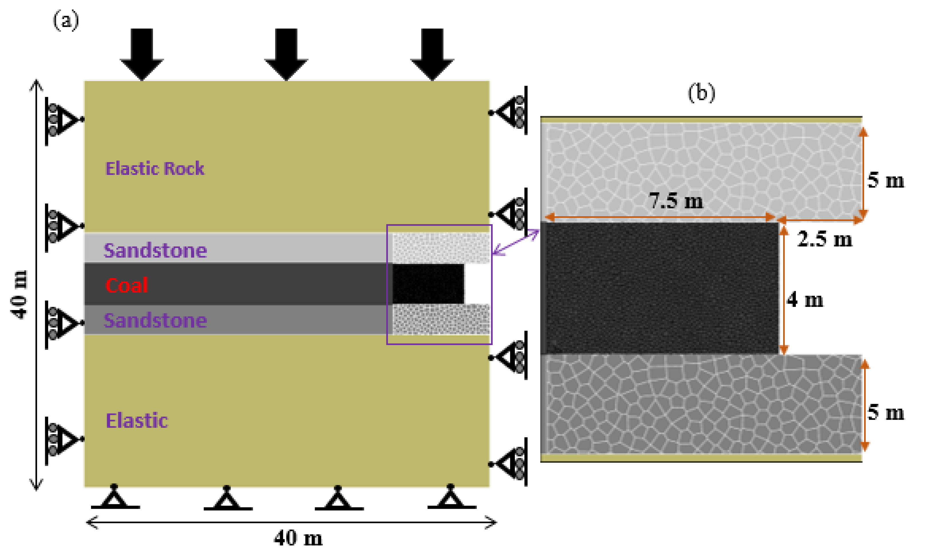
A numerical model with dimensions of 40 × 40 m was built to investigate how the coal rib responds to mechanical loading (see Figure 8). The vertical boundaries were equipped with a roller support while the horizontal boundaries of the model were fixed in the x- and y-directions, respectively, to prevent movements and rotations along these directions while a stress boundary condition was applied at the top of the model to achieve the desired simulated depth. To reduce computational effort, the Voronoi tessellation logic was used around the coal rib area only 7.5 m from the ribline (Figure 8). The vertical interface connecting the coal to the elastic region was given the calibrated coal microproperties. The average edge length of these polygonal Voronoi blocks was 0.08 m. The surrounding rock mass in the immediate roof and floor of the rib was discretized into much coarser blocks with an edge length of 0.4 m. The focus in this study was on the rib or sidewall failure mechanism. The interfaces connecting the coal to the roof and floor materials were assumed to have a friction angle of 30° and cohesion of 0.57 MPa [34]. The rest of the model was assumed to behave elastically. The review of the literature points to most ribs’ failures being mostly driven by stress and displacement. Consequently, the following were identified as key engineering factors influencing rib behavior: (1) Rib compressive loading resulting from roof and floor convergence. The source of this loading is mostly the overburden cover. (2) Horizontal deformation due to the Poisson’s Effect generated by vertical loading of the main body of the rib. (3) The geology and strength of the coal. (4) The displacement-driven rib support. (5) The properties of the interfaces between the roof-rib-floor system. This study investigates the rib stability control with the first four of these factors under consideration. Rib conditions become consistently worse as the depth of cover steadily increases. In situ stress measurements in US coal mines determined the ratio of in situ maximum horizontal to vertical stress to vary between 0.3 and 10.23 [35]. The most important concern in the design and construction of underground openings is the evaluation of stress and deformation that may be generated during or after construction. In this regard, three cases of overburden cover (200, 250, and 300 m) were employed in this paper to observe the rib behavior critically. The in situ stresses in the coal seam were initialized using the equations proposed by [36], while the in situ stresses in the rock layers used the recommendations of Esterhuizen found in [34]. The model was initially brought to equilibrium under these in situ stress conditions before the roadway was excavated. The supports were installed and the model was solved elastically to satisfy a second equilibrium state. This was performed to account for the initial elastic deformation that occurs before the supports can be installed.
4. Analysis of Modeling Results
4.1. Crack and Stress Damage Analysis
The rib damage due to crack development is assessed by recording the tensile and shear fractures development in the rib with increasing numerical solution steps and contact strength reduction. Figure 9 shows the shear and tension cracks development. Figure 10 presents the associated distribution of major principal stresses during the fracture development process. Generally, the rock fracture involves the generation, propagation, and coalescence of cracks. In Figure 9, the coal rib fractures under the vertical compression and as the length of cracks grow and propagate, the ribside gradually damages and weakens, reducing its ability to bear the load from the roof. The fracture development in the rib follows a typical bow-shaped pattern similar to the results of [34] (Figure 11). The cracks propagate inward, led by the dominant shear failure front. It is also worth noting that the rib damage and fracture development is predominantly driven by the tension fracture coalescence (Figure 9 and Figure 11). With the depth of cover increasing from 200 m to 300 m, the rib undergoes severe deformation and failure, with cracks propagating deep inside in a bow-shaped pattern. The immediate roof and floor, which is composed of sandstone with a UCS of 83.4 MPa, does not develop any visible cracks.
In a further analysis of the effect of fracture development on coal rib damage, Figure 9 demonstrates that at lower overburden cover, tensile cracks dominate the rib failure process while the shear cracks effect is most dominant with increasing depth. This observation highlights the role mining depth plays in assessing rib stability. The switch from tension-dominated rib damage to shear-dominated rib damage with increasing depth is a consequence of the increasing confinement of the coal mass experiences as the mining depth increases. The recorded depth of fracture in these 3 cases is 1.1 m, 1.6 m, and 1.8 m, respectively. The part of Figure 9 in the red dotted boundary is the fracture development that occurs just after excavation and before the coal mass strength reduction is applied. The rib is also unstable at these depths because of the increased load the rib has to bear at overburden covers of 250 m and 300 m. This can be observed in Figure 9. The gradients of the crack development appear to increase with solution steps for these depths compared with the almost horizontal curves for the 200 m overburden. The implication is that with increased solution steps, more cracks will be developed in these ribs.
At lower mining depths, the major principal stress is minimum in the outer rib line due to less confinement at this level of cover. With increasing depth, however, the stress concentration is much higher closer to the rib line. As shown in Figure 10, the two corners of the rib show ten (10) times the minimum stress concentration. The concentrated stress at these edges steers the generation of cracks from the corners, and as these cracks propagate to the inner rib, the dimension of the rib fracture zone is reduced as seen in Figure 9.
4.2. Deformation Damage Analysis
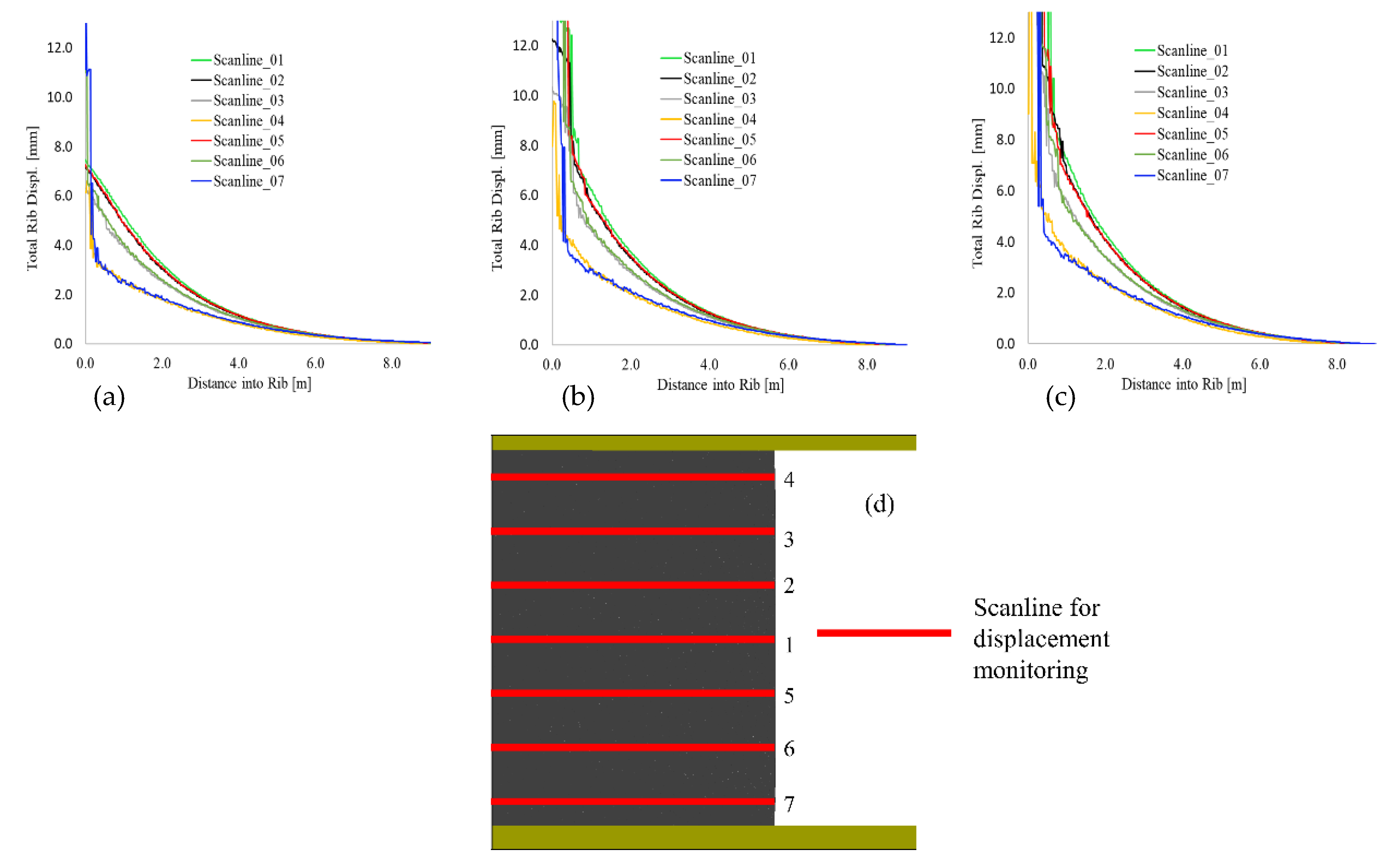
Mining depth is a significant parameter in evaluating rib stability. Thus, it is an important factor to consider when designing rib support systems. Gauna and Mark [37] assessed rib fatalities that occurred between 1996 and 2010 and found a strong correlation between fatalities, depth, and mining height. In this study, rib stability is assessed by defining the load applied on the rib resulting from the overburden cover and the integrity of the rib. Subject to the load from the mining depth, the coal rib compresses in the vertical direction and dilates in the horizontal direction. In this mechanism, assessing the horizontal displacement of the coal rib will present an insight into the effect of the overburden cover on rib damage development. The depth of cover contributes significantly to the induced stresses in coal pillar ribs. In this regard, 17.5 m long monitoring lines are set-up along the rib in the numerical model to record the lateral rib displacement. This setup is demonstrated in Figure 12d. The monitoring results (Figure 12) show the differences between the lateral displacements at different heights along the rib line. The results demonstrate that rib dilation is more severe in the middle section and that the minimum dilations are recorded closer to the roof and floor. This observation agrees with the fracture development as the bow-shaped cracked rib is deeper into the rib at the mid-section. Another important finding worth highlighting is that the severe rib dilation in the three cases falls in the range of 1–2 m into the rib. This has an important significance in the support design for this rib. Note also that the small dilation recorders near the roof and floor are a consequence of the robustness of the roof and floor properties. The failure mechanisms observed in this study may change significantly with different roof and floor properties.
4.3. Effect of Mining Height
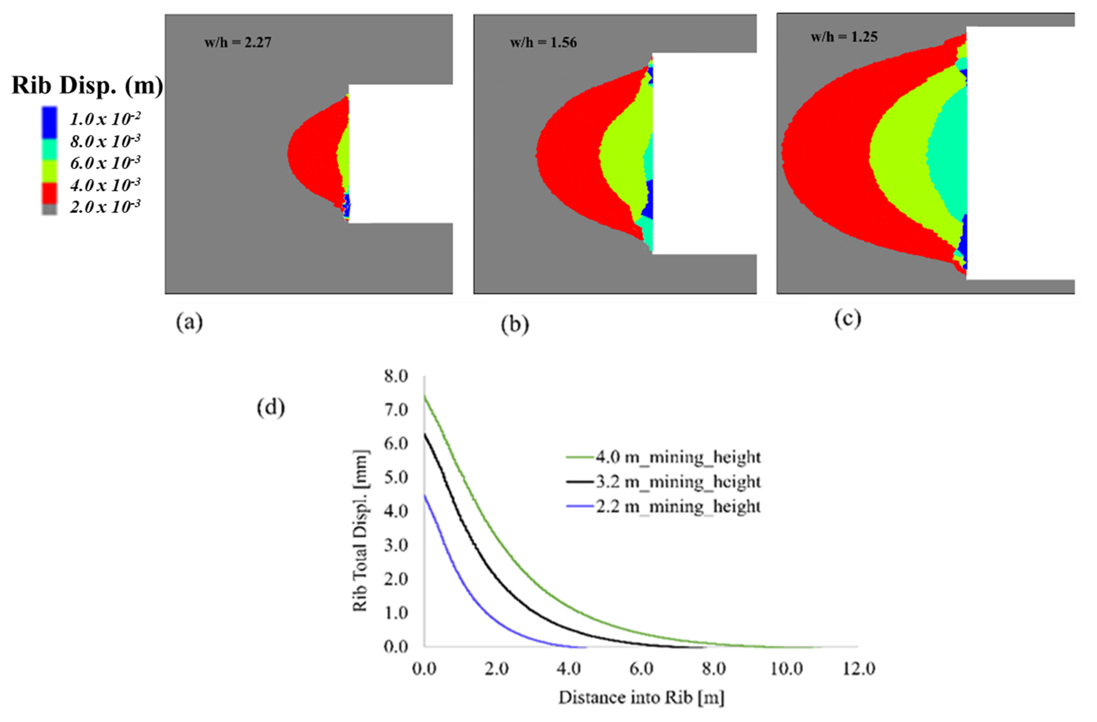
The Mine Safety and Health Administration recommends providing support systems in coal mines deeper than 210 m and with mining heights exceeding 2.1 m [38]. In this study, three set of models are developed to analyze the effect of mining height on rib performance. The models consist of a constant mining roadway width of 5 m at a constant overburden depth of 200 m and mining heights of 4.0 m, 3.2 m, and 2.2 m. Ribs operating above these geometries are usually supported in US coal mines [38]. These mining geometries result in excavation width-to-rib-height ratios of 1.25, 1.56, and 2.27, respectively. The models are solved by reducing the contact strength properties of the coal mass. Figure 13 presents the rib deformation results for these models. The results demonstrate that the larger the width-to-height ratio, the less deformation is recorded in the rib. The point worth taking away from these models is that the performance of the rib is much better at higher width-to-height ratios and that mining height is an important factor in the shape and rib yield zone extent.
4.4. Rib Support Evaluation
In most mining countries around the world, the roof support and control in underground coal mines have received great research with enough knowledge gained in understanding its mechanisms. This has resulted in a significant reduction in potential roof falls. An area that has received less attention compared with roof support is rib support, especially under the conditions where the rib spall is not well pronounced. In general, the scale of rib falls is usually smaller compared to the scale of roof falls; however, a chunk of coal or rock falling from rib has a serious potential risk of injury [39]. The practice in coal mines in the United States currently is to choose rib bolts of a specific diameter and length reactively. This is usually in response to the scale of rib falls and injuries that have occurred [22]. In practice, there are cases where the rib support can be easily determined through observations of the rib spall. However, in other instances, this ad hoc rib support design may lead to over-supported or under-supported ribs based on what is perceived through observations.
As observed in the previous sections, rib failure initiates due to the yielding of rib edges. The rib failure zones under the vertical stress distribution can be classified into three: crushed/spalled zone, yielded zone, and elastic zone (also see Figure 2). The crushed or spalled zone is usually dominated by fractures, therefore rendering this zone weak and soft. The yielded zone separates the crushed zone from the inner elastic core. It is a plastic zone in which coal yielding has occurred and its extent is defined by the peak vertical stress in the rib. The primary factor defining these three zones is the magnitude of the vertical stress the rib has to bear. Also noted previously is that the mining height influences the depth of rib fracture in addition to other factors such as rock partings, the interfaces between the rib and roof/floor, and the cleats system in the coal. These other factors are not part of the scope of this study.
Mine rib bolts are generally considered to perform the functions of reinforcement derived from the steel bar section that is usually installed into the rock strata. The steel bar provides shear resistance along its length and, as a consequence, limits the deformation of the rock mass. The opening of pre-existing cracks may be constrained in this setup. Additionally, the bar provides shear resistance along pre-existing fractures to constrain the sliding and rotation of blocks. The faceplate on the bolts provides confinement on the rib surface, consequently increasing the strength of the rock mass. The combined effect of reinforcement and support limits the generation, propagation, and interaction of fractures. With this action, the rock bolt reinforcement usually results in providing a stabilizing effect to the supported rock mass.
The function of rock support in restraining the deformation and failure of coal mine ribs is investigated using the DEM Voronoi logic. The “Cable” element in UDEC is employed to simulate the rock bolts and cables and the “Beam” element is employed to simulate the bolt faceplates. The properties of these support components used in this study are presented in Table 3. These properties are chosen based on the works of [40] for banded bright coal material, the same coal material we use in this study. Additional information about the functions of these support and reinforcement elements can be found in [3].
The effect of the rib support design is investigated by comparing the response of the models with and without rock bolts and various cable bolt geometries at a constant bolt diameter of 19 mm. The cable support geometries used for the simulation are presented in Table 4. Modeling is conducted for a two- and three-cable-bolt-supported rib. This part aims to demonstrate the reinforcement due to rock bolts, to quantify the increase in safety by defining a safety factor, and to determine the appropriate bolt geometry and length for the rib support. In practice, the bolts are installed after some amount of rib relaxation. To simulate this effect, the model is solved elastically before the bolt installation to satisfy a second equilibrium state after excavation.
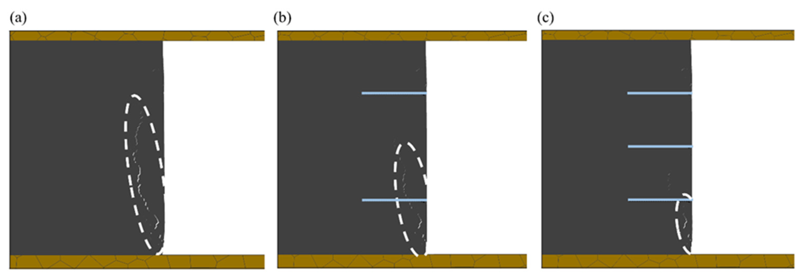
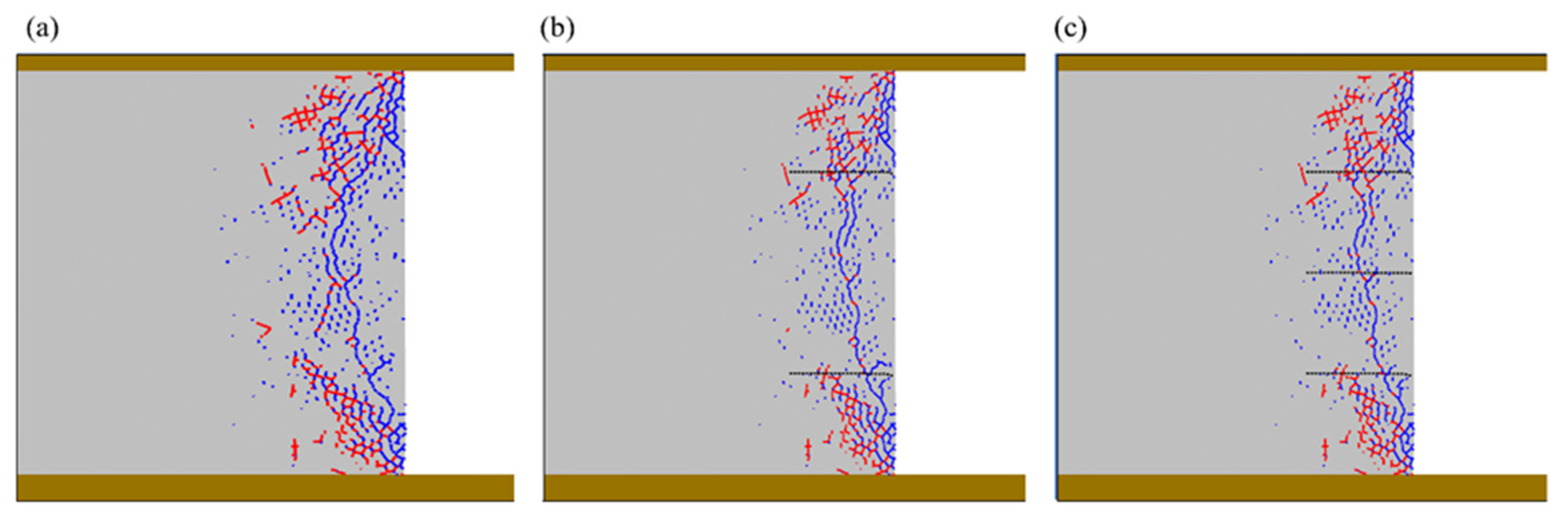
Figure 14 presents the effects of the rib bolt support on fracture development in the rib. There is a significant suppression of the macroscopic fracturing in the rib as a result of the installation of rock bolts. The opening of fractures is remarkably suppressed in the rib with a three-bolt case (Figure 14c). This highlights the important role of supports on rib stability. Once fracture development in the rib is suppressed, the portion of the rib still has the capacity to bear its design load. Fracture generation, opening, and sliding being suppressed by the support elements also implies there will be no further interactions of cracks. In a further evaluation of the support effect on rib stability, the contact states of the rib are plotted in Figure 15. This rib damage profile shows the fracture pattern of the rib with and without the support. It is evident from these results that the rib damage process in terms of contacts failure is suppressed in the rib case. There also appear to be no discernible difference between the two-bolt-supported and the three-bolt-supported rib. This raises the question of whether under these conditions, the middle cable support is needed (Figure 15c). These results show that the three-bolt row is not needed, as the two-bolt-supported rib is doing equally well in resisting fracture development in the rib.
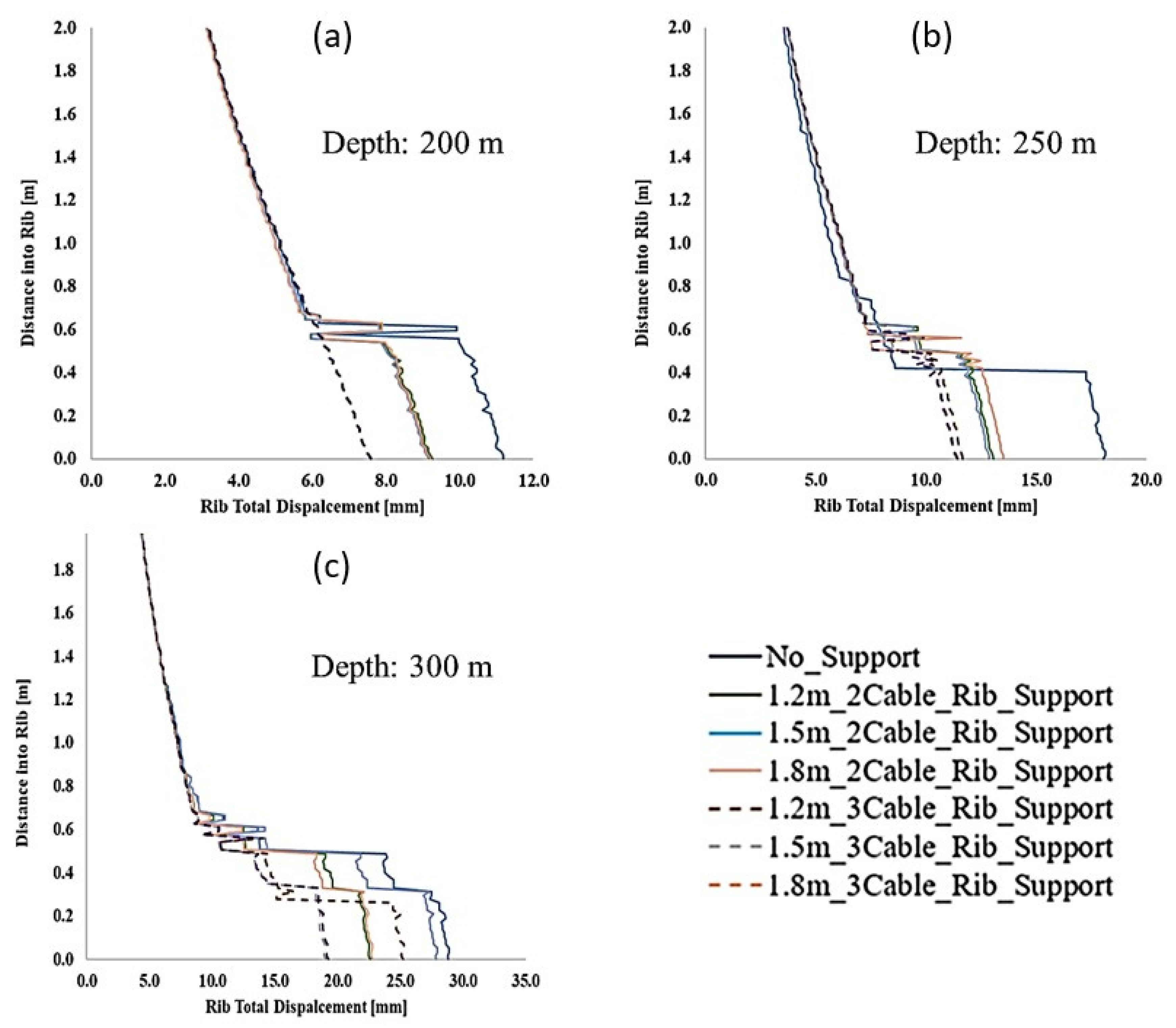
The effect of mining depth on rib support behavior is evaluated using the rib displacement plots in Figure 16. As expected, there is a general total rib displacement increase trend with depth. At shallower depths, the support effect for the three-bolt-supported and the two-bolt-supported ribs is clearly differentiated and there seems to be no effect on rib deformation when the bolt length is increased (Figure 16a). As the depth increases, however, the bolt length effect is demonstrated. It is important to note that at both the 250 m and 300 m overburden depths, the 1.5 m and 1.8 m have the same effect for the three-bolt-supported rib. This illustrates the fact that though longer rib bolts at higher depths may be required, there is a limiting depth at which increasing the bolt length has no positive effect. In this particular case, at the 250 m depth, the 1.2 m length cable is just sufficient to prove the rib support requirement. Increasing the bolt length at this depth only has a minimum to no effect in limiting rib deformation. This is, however, not the case at the 300 m overburden depth. Clearly, the 1.2 m bolt is not performing well even in the three-bolt-supported rib case. The only bolt support that gives consistent results in both support patterns is the 1.8 m bolt.
5. Practical Application
Applying numerical modeling to determine the rib support requirement is a robust but impractical approach. There are several factors observed to affect rib stability including rib composition, such as the strength of rib units, cleat density, cleat orientation entry direction with respect to cleat orientation, existence or absence of partings in the coal, and percentage of the extracted roof and/or floor rock [6]. It is impractical to consider all these influencing factors to determine the rib support requirement. Nevertheless, a well-calibrated numerical model can be used in conjunction with some field data to generate relevant information to help develop tables or a rating system for ribs based on some key influencing factors. Such tables and rating systems, considering the factors affecting the rib behavior and failure mechanism, can be helpful for practical rib support purposes.
This study is intended as a precursor to a broader study that will employ the approach presented to determine support requirements for various coal mines. This proposed future study will present the data in the format of tables or rating systems for practical application. The major influencing factor in this study is the depth of cover that has been observed to contribute significantly toward rib performance.
6. Conclusions
Determining the rib support requirement is a critical exercise; however, many factors that control this decision make it a challenging task to undertake. This study investigated previous rib support efforts and observed most of these to be purely experimental. This is ideally the best approach but considering the numerous variables at play and the labor intensity of failed data collection, it is not practical to exhaustively conduct experimentation to acquire the necessary data for rib support evaluation. Computational numerical modeling coupled with key rib stability influencing data can help develop an engineering-based support control protocol.
This study also investigated several rib failure cases considering the primary factor influencing rib behavior being the overburden depth. Additionally, the effect of mining height on rib deformation was also analyzed. Higher mining height results in higher rib deformation and, therefore, increased rib fracture development. These mechanisms will require a higher rib support density to control the rib performance. Increasing mining depths also increases the loading on the rib from the increased vertical stress. For example, at shallow depths, longer rib bolts supports may not be necessary, as they have the same effect as shorter bolts in reducing rib deformation. At these shallow depths also, lower rib bolt densities may be sufficient to control the rib failure mechanisms. This study demonstrates these shallower depths to be in the range of 200 m and below. At depths of 250 m and more, there is a noticeable impact of the support length on rib stabilization. However, increased depths do not correlate with increased bolts length to control rib deformation. While limitations exist, the presented methodology and the results obtained are considered as a considerable step toward the development of a rigorous rib support procedure for coal mines in the US.
Author Contributions
Conceptualization, M.S. and T.S.; methodology, M.S. and T.S.; software, M.S., T.S. and D.G; analysis, M.S.; writing—original draft preparation, M.S. and D.G.; writing—review and editing, T.S. and D.G.; visualization, M.S. and D.G.; supervision, T.S. All authors have read and agreed to the published version of the manuscript.
Funding
This research received no external funding.
Data Availability Statement
Not applicable.
Acknowledgments
The authors would like to acknowledge the support of the National Institute for Occupational Safety and Health (NIOSH) for their support in making this research possible.
Conflicts of Interest
The authors declare no conflict of interest.
References
- MSHA Fatality Reports|Mine Safety and Health Administration (MSHA 2021). Available online: https://bit.ly/2UMd0iE (accessed on 8 June 2021).
- Jones, T.; Klemetti, T.; Mohamed, K. Investiating the Contributing Factors to Rib Fatalities Through Historical Analysis. In Proceedings of the 33rd International Conference on Ground Control in Mining, Morgantown, WV, USA, 29–21 July 2014. [Google Scholar]
- ITASCA UDEC|US Minneapolis—Itasca Consulting Group, Inc. 2020. Available online: https://www.itascacg.com/software/UDEC (accessed on 11 June 2021).
- Shepherd, J. Assessment of Rib Instability Hazards for Strata Management Systems; University of Wollongong & the Australasian Institute of Mining and Metallurgy: Hongkong, China, 2002; p. 5. [Google Scholar]
- Rashed, G.; Mohamed, K.; Kimutis, R. A coal rib monitoring study in a room-and-pillar retreat mine. Int. J. Min. Sci. Technol. 2021, 31, 127–135. [Google Scholar] [CrossRef]
- Mohamed, K.M.; Tulu, I.B.; Murphy, M.M. Numerical model calibration for simulating coal ribs. In Proceedings of the Proceedings of the 35th International Conference on Ground Control in Mining, Morgantown, WV, USA, 26–28 July 2016; pp. 289–298. [Google Scholar]
- Mohamed, K.; Dyke, M.; Rashed, G.; Sears, M.M.; Kimutis, R. Preliminary rib support requirements for solid coal ribs using a coal pillar rib rating (CPRR). Int. J. Min. Sci. Technol. 2021, 31, 15–22. [Google Scholar] [CrossRef]
- Mohamed, K.; Rashed, G.; Radakovic-Guzina, Z. Loading characteristics of mechanical rib bolts determined through testing and numerical modeling. Int. J. Min. Sci. Technol. 2020, 30, 17–24. [Google Scholar] [CrossRef] [PubMed]
- O’Beirne, T.; Shepherd, J. The Failure of Coal Pillar Ribs and Possible Methods of Control. In Proceedings of the New Zealand Conference on Geomechanics, Perth, Australia, 14–18 May 1984; pp. 661–667. [Google Scholar]
- O’Beirne, T.J. Instability and Support of Coal Mine Ribs; Australian Coal Industry Research Laboratories Ltd: Mulgrave, Australia, 1987. [Google Scholar]
- Smith, W.C. Rib Stability: Practical Considerations to Optimize Rib Design; U.S. Department of the Interior, Bureau of Mines: Washington, DC, USA, 1992. [Google Scholar]
- Fabjanczyk, M.; Tarrant, G.; Guy, R. Summary Report No.2—Factors Affecting Design of Rib Reinforcement, as part of Final Report for AMIRA Project No. In P207S—Optimisation of Coal Mine Roof/Rib Reinforcement and Design Methods, 1992. [Google Scholar]
- Salamon, M.D.G. A Coal Seam with Strainsoftening Properties Embedded in a Stratified Rock Mass; UNSW School of Mine: Randwick, Australia, 1992. [Google Scholar]
- Quinteiro, C.; Galvin, J.; Salamon, M.D.G. Coal Pillar Yield Mechanics. In Proceedings of the 8th ISRM Congress, Tokyo, Japan, 25–29 September 1995; Available online: https://onepetro.org/isrmcongress/proceedings/CONGRESS95/All-CONGRESS95/ISRM-8CONGRESS-1995-253/169309 (accessed on 23 June 2021).
- Hebblewhite, B.; Lin, B.; Galvin, J.; Walker, R.; Calleja, J.D. Rib Mechanics and Support Systems. In Proceedings of the International Conference on Geomechanics/Ground Control in Mining and Underground Construction, Wollongong, Australia, 14–17 July 1998; pp. 403–412. [Google Scholar]
- Frith, R.; Ditton, S. Stage 1 and 2 Monitoring Report for Geomechanics of Rib Failure and Development of Appropriate Support Technology. ACIRL Report EGE 3087/1. 1993. [Google Scholar]
- Kent, L.; Bigby, D. Falls of Ground Risks in Coal Mines Face Roadways. 2001. Available online: http://www.hse.gov.uk/research/crr_pdf/2001/crr01368.pdf (accessed on 7 August 2021).
- Bigby, D.; Cassie, J. Stability and Support of Sides of Mine Roadways. 2003. Available online: https://www.hse.gov.uk/research/rrhtm/rr153.htm (accessed on 1 August 2021).
- Colwell, M. Analysis and Design of Rib Support (ADRS)–A Rib Support Design Methodology for Australian Collieries. Final Report-ACARP Project C11027. 2005. [Google Scholar]
- Colwell, M.G. A Study of the Mechanics of Coal Mine Rib Deformation and Rib Support as a basis for Engineering Design. Ph.D. Thesis, University of Queensland, St Lucia, Australia, 2006. [Google Scholar]
- Heritage, Y. Mechanics of rib deformation—Observations and monitoring in Australian coal mines. Int. J. Min. Sci. Technol. 2019, 29, 119–129. [Google Scholar] [CrossRef]
- Mohamed, K.M.; Tulu, I.B.; Klemetti, T. Numerical Simulation of Deformation and Failure Process of Coal-Mass. In Proceedings of the 49th U.S. Rock Mechanics/Geomechanics Symposium, San Francisco, CA, USA, 28 June–1 July 2015; Available online: https://www.onepetro.org/conference-paper/ARMA-2015-363 (accessed on 14 July 2021).
- Gao, F.Q.; Stead, D. The application of a modified Voronoi logic to brittle fracture modelling at the laboratory and field scale. Int. J. Rock Mech. Min. Sci. 2014, 68, 1–14. [Google Scholar] [CrossRef]
- Kazerani, T.; Zhao, J. Micromechanical parameters in bonded particle method for modelling of brittle material failure. Int. J. Numer. Anal. Methods Geomech. 2010, 34, 1877–1895. [Google Scholar] [CrossRef]
- Kazerani, T. Effect of micromechanical parameters of microstructure on compressive and tensile failure process of rock. Int. J. Rock Mech. Min. Sci. 2013, 64, 44–55. [Google Scholar] [CrossRef]
- Lisjak, A.; Grasselli, G. A review of discrete modeling techniques for fracturing processes in discontinuous rock masses. J. Rock Mech. Geotech. Eng. 2014, 6, 301–314. [Google Scholar] [CrossRef] [Green Version]
- Brady, B.H.G.; Brown, E. Rock Mechanics for Underground Mining, 3rd ed.; Springer Science & Business Media: New York, NY, USA, 2006; p. 628. ISBN 978-1-4020-2064-3. [Google Scholar]
- Sunkpal, M.; Sherizadeh, T. Exploring the Deformation Mechanics of Coal Ribs Using the Distinct Element Modeling Approach. Rock Mech. Rock Eng. 2022, 55, 2879–2898. [Google Scholar] [CrossRef]
- Rusnak, J. Coal Strength Variation by Lithotype for High-Volatile A Bituminous Coal in the Central Appalachian Basin. In Proceedings of the 36th International Conference on Ground Control in Mining, Morgantown, WV, USA, 25–27 July 2018. [Google Scholar]
- Nie, D.N. Experimental analysis of the post-failure behavior of coal and rock under laboratory compression tests. In Graduate Theses, Dissertations, and Problem Reports; West Virginia University ProQuest Dissertations Publishing: Morgantown, WV, USA, 2011. [Google Scholar]
- Hoek, E.; Martin, C.D. Fracture initiation and propagation in intact rock—A review. J. Rock Mech. Geotech. Eng. 2014, 6, 287–300. [Google Scholar] [CrossRef] [Green Version]
- Cai, M.; Kaiser, P.K.; Tasaka, Y.; Maejima, T.; Morioka, H.; Minami, M. Generalized crack initiation and crack damage stress thresholds of brittle rock masses near underground excavations. Int. J. Rock Mech. Min. Sci. 2004, 41, 833–847. [Google Scholar] [CrossRef]
- Xue, L.; Qin, S.; Sun, Q.; Wang, Y.; Lee, L.M.; Li, W. A Study on Crack Damage Stress Thresholds of Different Rock Types Based on Uniaxial Compression Tests. Rock Mech. Rock Eng. 2014, 47, 1183–1195. [Google Scholar] [CrossRef]
- Mohamed, K.M.; Cheng, Z.; Rashed, G. Coal Rib Stability Based on the Strength Reduction of the Coal Mass Model. In Proceedings of the 53rd U.S. Rock Mechanics/Geomechanics Symposium, New York, NY, USA, 23–26 June 2019; Available online: https://onepetro.org/ARMAUSRMS/proceedings/ARMA19/All-ARMA19/ARMA-2019-2844/125175 (accessed on 2 July 2021).
- Mark, C.; Mucho, T.P. Longwall Mine Design for Control of Horizontal Stress. 1994. Available online: https://www.osti.gov/etdeweb/biblio/7151053 (accessed on 25 June 2021).
- Liu, H.; Sang, S.; Xue, J.; Wang, G.; Xu, H.; Ren, B.; Liu, C.; Liu, S. Characteristics of an in situ stress field and its control on coal fractures and coal permeability in the Gucheng block, southern Qinshui Basin, China. J. Nat. Gas Sci. Eng. 2016, 36, 1130–1139. [Google Scholar] [CrossRef] [Green Version]
- Gauna, M.; Mark, C. Protecting Underground Coal Miners From Rib Falls. In Proceedings of the Proceedings of the 30th International Conference on Ground Control in Mining, Morgantown, WV, USA, 26–28 July 2011; p. 9. [Google Scholar]
- Mohamed, K.M.; Murphy, M.M.; Lawson, H.E.; Klemetti, T. Analysis of the current rib support practices and techniques in U.S. coal mines. Int. J. Min. Sci. Technol. 2016, 26, 77–87. [Google Scholar] [CrossRef] [PubMed] [Green Version]
- Zhang, P.; Mohamed, K.M.; Trackemas, J. Coal Rib Failure and Support in Longwall Gate Entries. In Proceedings of the 51st U.S. Rock Mechanics/Geomechanics Symposium, San Francisco, CA, USA, 25–28 June 2017; Available online: https://onepetro.org/ARMAUSRMS/proceedings/ARMA17/All-ARMA17/ARMA-2017-0886/124514 (accessed on 24 July 2021).
- Zipf, K. Numerical Modeling Procedures for Practical Coal Mine Design. In Proceedings of the Golden Rocks 2006, The 41st U.S. Symposium on Rock Mechanics (USRMS), Golden, CO, USA, 17–21 June 2006; Available online: https://onepetro.org/ARMAUSRMS/proceedings/ARMA06/All-ARMA06/ARMA-06-1119/116045 (accessed on 22 February 2021).
Figure 1.
An idealized rib deformation schematic and Stanchion data plot showing horizontal rib movements along the rib line.
Figure 1.
An idealized rib deformation schematic and Stanchion data plot showing horizontal rib movements along the rib line.

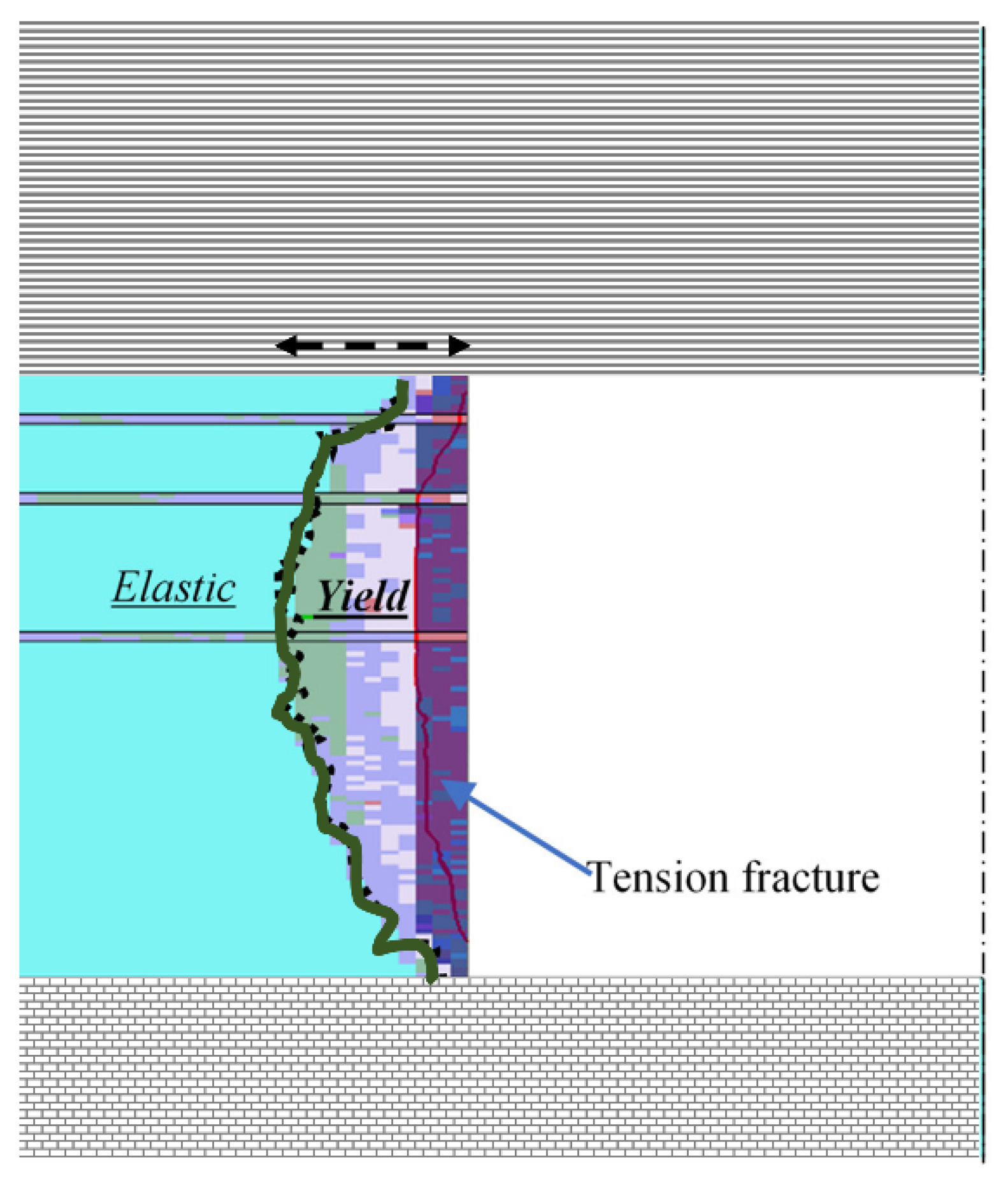
Figure 2.
Coal rib failure zones development (modified from [14]).
Figure 2.
Coal rib failure zones development (modified from [14]).

Figure 3.
Idealization of the lateral extent of roof fracturing and its impact on rib Loading. (a) Unfractured rib due to cantilever effect in the roof absorbing deadweight. (b) Fractured rib: weight of fractured rock absorbed by rib (after [16]).
Figure 3.
Idealization of the lateral extent of roof fracturing and its impact on rib Loading. (a) Unfractured rib due to cantilever effect in the roof absorbing deadweight. (b) Fractured rib: weight of fractured rock absorbed by rib (after [16]).

Figure 4.
Example rib deformation characteristics: (a) compressive-driven rib failure, (b) shear-driven rib failure, (c) slabbing rib failure, and (d) toppling failure (after [18]).
Figure 4.
Example rib deformation characteristics: (a) compressive-driven rib failure, (b) shear-driven rib failure, (c) slabbing rib failure, and (d) toppling failure (after [18]).

Figure 5.
UDEC calculation principle of the rock fracture propagation process (redrawn after [26]).
Figure 5.
UDEC calculation principle of the rock fracture propagation process (redrawn after [26]).

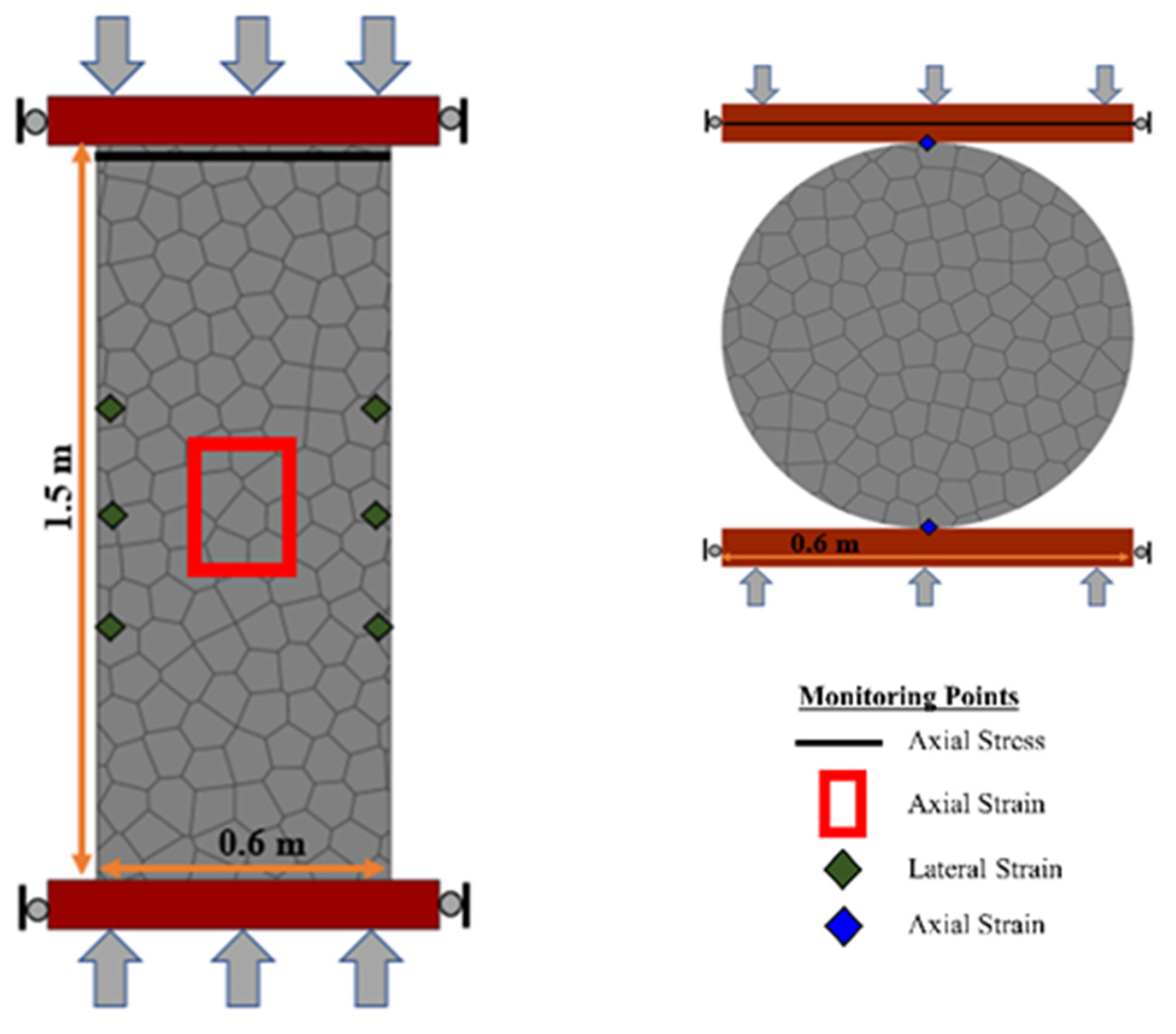
Figure 6.
Geometry, boundary conditions, and monitoring locations of the UCS and indirect tensile strength tests.
Figure 6.
Geometry, boundary conditions, and monitoring locations of the UCS and indirect tensile strength tests.

Figure 7.
(a) The coal mass uniaxial compressive (b) and tensile tests, comparing the results from the coal mass model in FLAC3D and the simulated stress–strain curves in UDEC. Also included is the crack–strain curves for the coal mass.
Figure 7.
(a) The coal mass uniaxial compressive (b) and tensile tests, comparing the results from the coal mass model in FLAC3D and the simulated stress–strain curves in UDEC. Also included is the crack–strain curves for the coal mass.

Figure 8.
(a) Model boundary conditions and geometry configuration, (b) Voronoi tessellation logic zone.
Figure 8.
(a) Model boundary conditions and geometry configuration, (b) Voronoi tessellation logic zone.

Figure 9.
Shear and tensile fracture development in the rib at overburden covers of 200 m, 250 m, and 300 m at coal mass reduction of 1.8.
Figure 9.
Shear and tensile fracture development in the rib at overburden covers of 200 m, 250 m, and 300 m at coal mass reduction of 1.8.

Figure 10.
Major principal stress distribution in the rib during fracturing process as the strength of the coal mass is reduced by 1.80.
Figure 10.
Major principal stress distribution in the rib during fracturing process as the strength of the coal mass is reduced by 1.80.

Figure 11.
Bow-shaped rib failure process [34].
Figure 11.
Bow-shaped rib failure process [34].

Figure 12.
Rib displacements. (a) 200 m overburden, (b) 250 m overburden, (c) 300 m overburden, and (d) Monitoring lines.
Figure 12.
Rib displacements. (a) 200 m overburden, (b) 250 m overburden, (c) 300 m overburden, and (d) Monitoring lines.

Figure 13.
Rib deformation results. (a) w/h = 2.27, (b) w/h = 1.56, (c) w/h = 1.56, and (d) the displacement plot in the middle of the rib.
Figure 13.
Rib deformation results. (a) w/h = 2.27, (b) w/h = 1.56, (c) w/h = 1.56, and (d) the displacement plot in the middle of the rib.

Figure 14.
Macro-fracture development in the rib. (a) Unsupported; (b) 2-cable-bolted rib; (c) 3-cable-bolted rib at overburden depth of 250 m and contact strength reduction of 2.0.
Figure 14.
Macro-fracture development in the rib. (a) Unsupported; (b) 2-cable-bolted rib; (c) 3-cable-bolted rib at overburden depth of 250 m and contact strength reduction of 2.0.

Figure 15.
Rib damage profile in terms of the contact failure state. (a) Unsupported; (b) 2-cable-bolted rib; (c) 3-cable-bolted rib at overburden depth of 250 m and contact strength reduction of 1.60.
Figure 15.
Rib damage profile in terms of the contact failure state. (a) Unsupported; (b) 2-cable-bolted rib; (c) 3-cable-bolted rib at overburden depth of 250 m and contact strength reduction of 1.60.

Figure 16.
The simulated effect of cable rock bolting on mine rib deformation. (a) at depth 200 m, (b) at depth 250 m, (c) at depth 300 m.
Figure 16.
The simulated effect of cable rock bolting on mine rib deformation. (a) at depth 200 m, (b) at depth 250 m, (c) at depth 300 m.


Table 1.
Simulation parameters for coal and rock specimens.
| Intact Rock Properties | Coal [29] | Sandstone [30] |
|---|---|---|
| Poisson’s ratio (-) | 0.25 | 0.3 |
| Young’s modulus (GPa) | 2.55 | 23.44 |
| Uniaxial compressive strength (MPa) | 19.70 | 84.30 |
| Tensile Strength (MPa) | 1.97 | 8.43 (10% of UCS) |
| Rock and coal mass properties | ||
| Poisson’s ratio (-) | 0.20 | 0.25 |
| Young’s modulus (GPa) | 2.55 | 8.87 |
| Uniaxial compressive strength (MPa) | 6.55 | 48.90 |
| Tensile Strength (MPa) | 0.66 (10% of UCS) | 4.90 (10% of UCS) |
Table 2.
Calculated mechanical properties for the laboratory and in situ strength of the coal and sandstone rocks.
Table 2.
Calculated mechanical properties for the laboratory and in situ strength of the coal and sandstone rocks.
| Properties | Coal Mass | Rock Mass | |
|---|---|---|---|
| Rock matrix | Young’s modulus (GPa) | 2.55 | 18.0 |
| Poisson’s ratio (-) | 0.20 | 0.25 | |
| Contact | Shear stiffness, (GPa/m/m) | 41.2 | 250.0 |
| Normal stiffness, (GPa/m/m) | 103.0 | 2760.0 | |
| 0.4 | 0.10 | ||
| Cohesion, (MPa) | 5.0 | 26.0 | |
| Friction angle, (degrees) | 0.0 | 0.0 | |
| Tensile strength, (MPa) | 1.70 | 12.0 | |
| Residual friction angle, (degree) | 25.0 | 35.0 | |
| Residual tensile strength, (MPa) | 0.0 | 0.0 | |
| Residual cohesion, (MPa) | 0.0 | 0.0 |
Table 3.
Properties of support elements used in the BBM model.
| Cable | Grout | Beam | ||||||||||
|---|---|---|---|---|---|---|---|---|---|---|---|---|
| Density (kg/m3) | Young’s Modulus (GPa) | Yield Stress (MPa) | Yield Strength (kN) | Failure Strain (%) | Stiffness Kbond (MN/m/m) | Shear Sbond (kN/m) | Shear Modulus (GPa) | Young’s Modulus (GPa) | Yield Stress (MPa) | Interface Normal Stiffness (GPa/m) | Interface Shear Stiffness (GPa/m) | Interface Friction (deg.) |
| 7800.00 | 200.00 | 500.00 | 200.00 | 15.00 | 1.92 | 750.00 | 9.00 | 200.00 | 500.00 | 10.00 | 10.00 | 35 |
Table 4.
Rock bolt length and rib depth for model simulation.
| Depth (m) | Coal Rib Bolt Length (m) | ||
|---|---|---|---|
| 200 | 1.2 | 1.5 | 1.8 |
| 250 | |||
| 300 | |||
Disclaimer/Publisher’s Note: The statements, opinions and data contained in all publications are solely those of the individual author(s) and contributor(s) and not of MDPI and/or the editor(s). MDPI and/or the editor(s) disclaim responsibility for any injury to people or property resulting from any ideas, methods, instructions or products referred to in the content. |
© 2023 by the authors. Licensee MDPI, Basel, Switzerland. This article is an open access article distributed under the terms and conditions of the Creative Commons Attribution (CC BY) license (https://creativecommons.org/licenses/by/4.0/).
Share and Cite
MDPI and ACS Style
Sunkpal, M.; Sherizadeh, T.; Guner, D. Evaluating the Effect of Overburden Depth, Mining Height, and Support Density on Coal Rib Damage Using DEM Modeling. Geosciences 2023, 13, 77. https://doi.org/10.3390/geosciences13030077
AMA Style
Sunkpal M, Sherizadeh T, Guner D. Evaluating the Effect of Overburden Depth, Mining Height, and Support Density on Coal Rib Damage Using DEM Modeling. Geosciences. 2023; 13(3):77. https://doi.org/10.3390/geosciences13030077
Chicago/Turabian StyleSunkpal, Maurice, Taghi Sherizadeh, and Dogukan Guner. 2023. "Evaluating the Effect of Overburden Depth, Mining Height, and Support Density on Coal Rib Damage Using DEM Modeling" Geosciences 13, no. 3: 77. https://doi.org/10.3390/geosciences13030077
Note that from the first issue of 2016, this journal uses article numbers instead of page numbers. See further details here.