
Increasing the Force Exertion of a Soft Actuator Using Externally Attachable Inter-Chamber Plates


Department of Mechatronics and Automation, Faculty of Engineering, University of Szeged, 6725 Szeged, Hungary
*
Author to whom correspondence should be addressed.
Actuators 2023, 12(6), 222; https://doi.org/10.3390/act12060222
Submission received: 19 April 2023
/
Revised: 15 May 2023
/
Accepted: 26 May 2023
/
Published: 27 May 2023
(This article belongs to the Special Issue Recent Advances in Pneumatic Soft Actuators)
Abstract
:The application of soft actuators has become increasingly common in wearable devices. In this study, we investigated the force characteristics of soft actuators made entirely of elastic material, when equipped with solid external chamber plates of varying thickness that can be attached from the outside. This study examines the effect of these plates on the force characteristics of a fully silicone-based fifteen-chamber soft actuator without any non-stretchable internal components. The parameters of the actuator were determined with consideration of wearable applications, such as rehabilitation devices and exoskeletons. The observed differences in the behavior of the actuator at various pressure levels and plate thicknesses were measured. Furthermore, the effect of the externally inserted plates between the chambers on the passive bending of the actuator was examined. The obtained results were evaluated and compared to determine how external chamber plates of given thicknesses affect the operational performance of a soft actuator.
1. Introduction
Actuator technology has enabled robot systems to perform all assigned tasks accurately, precisely, quickly, and efficiently [1]. However, there has been a demand for collaborative, physically safe, and wearable applications that can work with humans [2,3]. Adaptability and flexibility are outstanding features of biological systems, and they tend to strive for simplicity and show reduced complexity in their interactions with the environment. Based on these biological systems, a new class of machines has been defined as soft actuators [4,5]. These systems contain soft elements instead of rigid structures, such as pneumatic artificial muscles (PAMs) [6,7], fluidic elastomer actuators (FEAs) [8] or dielectric elastomer actuators (DEAs) [9], allowing them to perform tasks that traditional robotic systems cannot. Soft robotics enable the design of systems that efficiently adapt to the environment and undefined events. These functions open new possibilities for designing soft machines that can be used in medical science [10,11], grasping techniques [12,13], designing biological-inspired robots [14], and human–machine collaboration. The latest developments are directed towards human–robot interaction [15,16], with special attention paid to wearable exoskeleton designs [17,18].
Despite the future-oriented research, there are still certain problems that need to be considered in the design of soft actuators. As soft actuators are made of elastic materials and typically operate using compressed air, they have many drawbacks, such as low repeatability and hysteresis error [19], complicated manufacturing processes [20], material vulnerability [21], and difficulty in controlling motion [22,23]. In addition, the energy efficiency of soft robots is relatively low, as most of the energy is lost due to unwanted deformations. Therefore, much of the research focuses on increasing the bending performance of these devices and the force generated by bending. There are various methods to achieve and improve the proper bending motion, force generation, and motion performance of soft actuators. By selecting the appropriate physical parameters of the actuator [24] and designing an origami-like outer shell [25], the desired motion, force, and performance can be achieved, even when the actuator is made from a single material. Much of the research aims to create desired movements by combining different materials, such as using various non-stretchable fibers or fabrics [26,27,28] to restrict expansion incorporated into the actuator body, combining materials with different levels of elasticity within a single actuator [29], or modifying or improving actuator properties using external, retrofittable elements [30,31,32].
This study has examined the physical performance of fully elastic soft actuators with externally attachable inter-chamber plates. In the case of soft actuators equipped with parallel chamber walls, the bending motion and exertion of force greatly depend on the interaction of the chamber walls [33]. In the current study, plates of various sizes are externally installed between the chambers of a fully elastic material soft actuator consisting of fifteen segments, whose role is to fill the gap between the chambers and thereby increase bending performance. In Section 2 of this study, a detailed description of the physical parameters, manufacturing process, and material properties of the actuator and inter-chamber plates are presented, along with an account of the measurement device and its design, using which the measurement and evaluation were carried out. Section 3 discusses the compilation, process, and results of the measurements. The discussion of the experimental results is contained in Section 4. Section 5 presents the conclusions and prospects for future work.
2. Materials and Methods
2.1. Structural Design and Fabrication of Soft Actuator
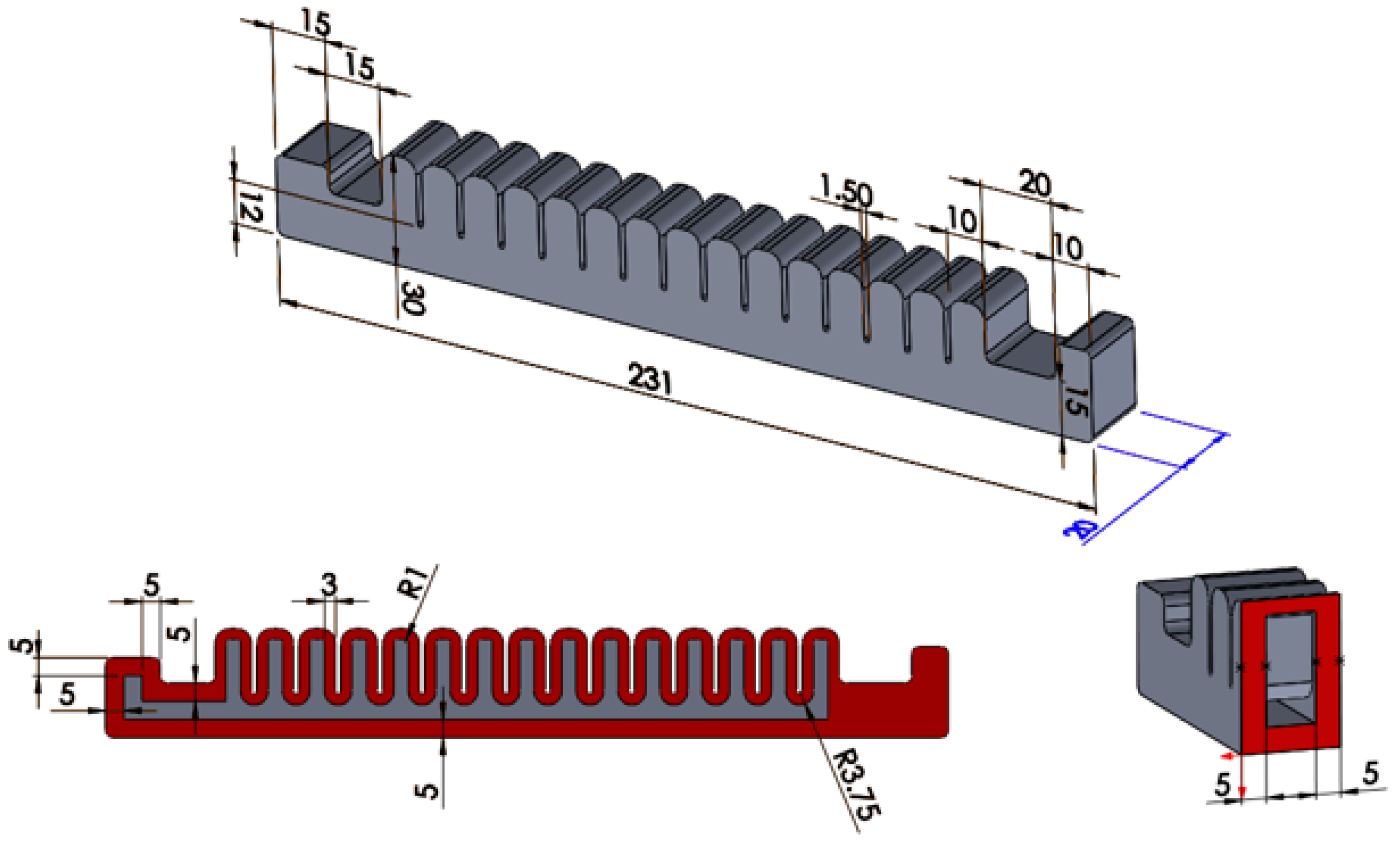
One of the major challenges with pneumatic multi-chambered soft actuators is to ensure that most of the invested energy is utilized for motion in the appropriate direction. This can be achieved by incorporating different non-elastic materials into the actuator body, but their application significantly complicates the production process. The most common form of production is casting, which involves using molds to produce the hollow chamber networks. Essentially, a two-step process is used to achieve this, where in the first process, the internal structure of the chambers is formed, and in the second step, the actuator is sealed with a closing layer. However, if new layers of materials are incorporated into the actuator body to reduce stretching, this process can increase by at least one, or possibly more steps, as the new material will need a closing layer to function as a part of the actuator. Actuators made of fully elastic materials exhibit lower bending performance than composite types, as unintended deformations can appear on the actuator. These deformations can be reduced by incorporating non-stretchable materials, but their integration into the actuator increases the production steps due to the application of additional sealing layers. A fully elastic material-made actuator was designed, whose exertion properties are modified with the help of plates discussed in later sections. The geometric parameters of the actuator are shown in Figure 1.
The primary task of the actuator is to create a bending motion. Since the actuator has a homogeneous structure, the optimal selection of wall thicknesses determines the degree of motion generated during operation. To achieve motion with the appropriate directionality, the wall thickness of the lower portion of the actuator (5 mm) differs significantly from the thickness of the other walls (3 mm), thereby ensuring that the lower layer restricts stretching to a greater extent during operation.
The geometrical parameters of the actuator were determined to resemble actuators used in rehabilitation devices or exoskeletons. Therefore, the actuator has a length of 231 mm, a width of 20 mm, and consists of 15 chambers. Segments were designed at the front and rear of the actuator to facilitate the attachment of the device during the measurements, which is discussed in a later section.
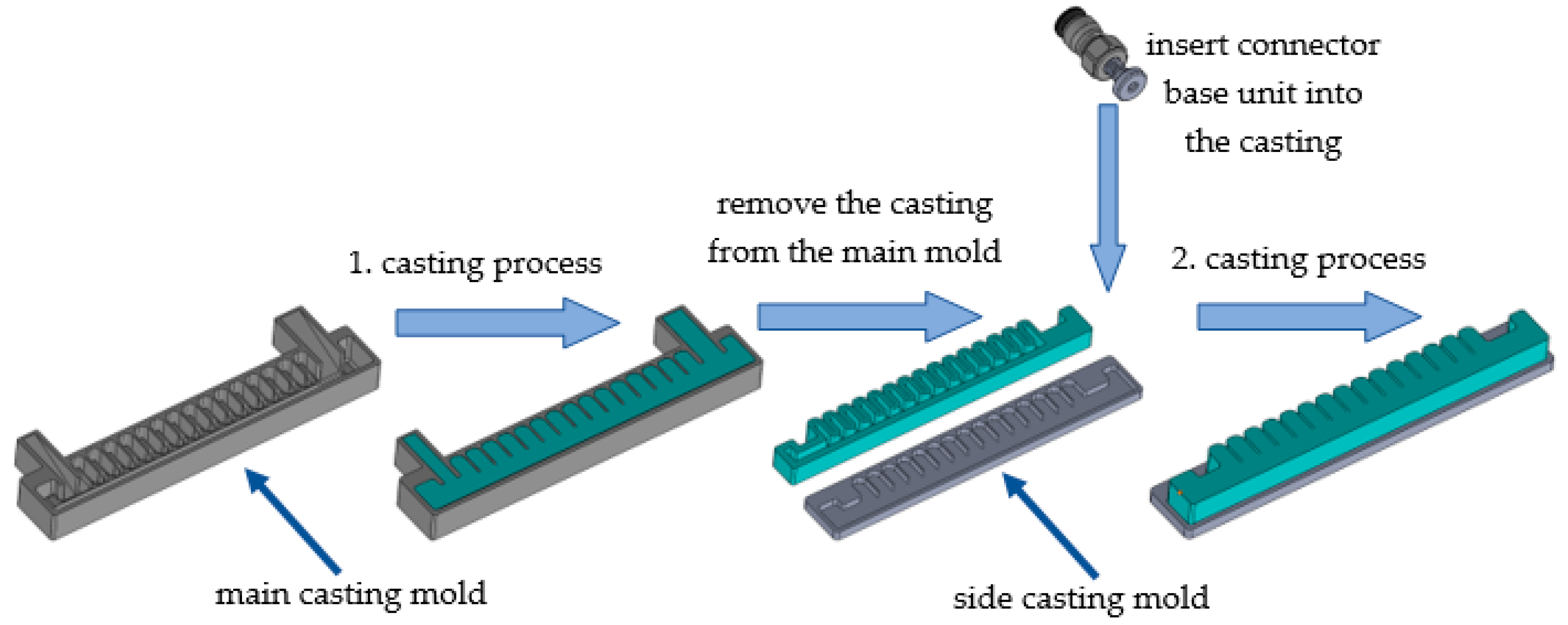
The actuators were produced using a two-step casting process, which required the design of two casting molds: a main mold and a side mold. The main mold was responsible for designing the main external and internal geometry of the actuator, as shown in Figure 2. The main casting mold was responsible for designing the side walls of the chambers, the bottom of the actuator, one side wall, and the two attachment segments at either end (one of which also contained the power supply channel).
The side casting mold was responsible for closing off the actuator and designing the side of the device, as shown in Figure 2. The casting molds were produced using a CraftBot Plus FDM 3D printer with Herz brand 1.75 mm diameter PLA filament. The printing parameters both of the molds are shown in Table 1.
Mold Max 40 casting silicone was selected as the actuator material. This is a Shore A 40 hardness tin-catalyzed silicone rubber with an elongation at break of 250%, a tensile strength of 3.79 MPa, and an elastic modulus of 1.31 MPa.
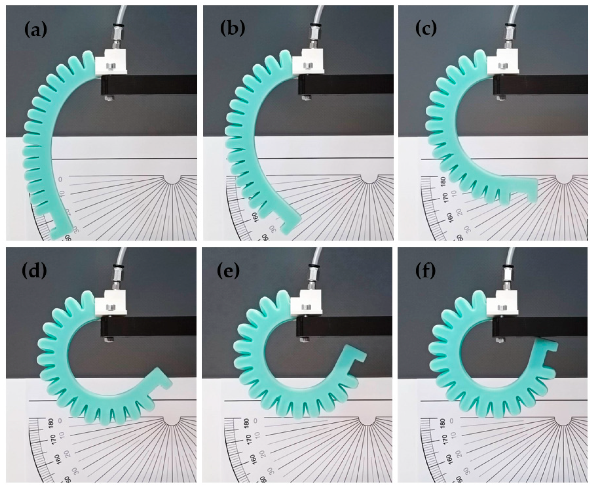
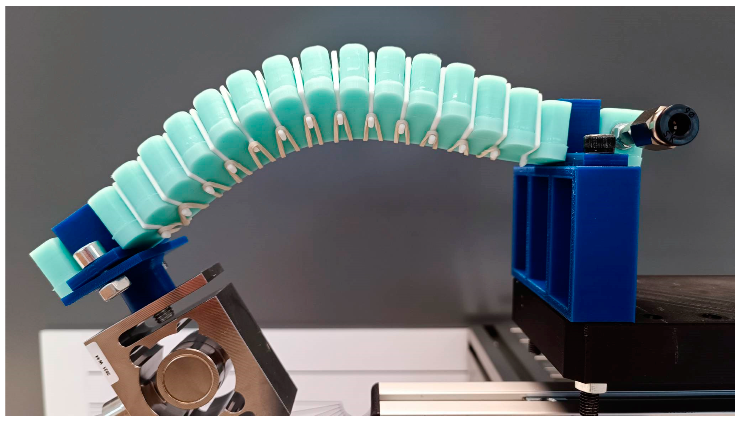
A connector base unit must be placed inside the semi-finished actuator structure taken out of the main mold to ensure the connection to the air network. This is a drilled cylinder with an 8 mm diameter edge and an M5 metric thread, see Figure 2, which is placed inside the actuator during this phase of casting. The threaded section ensures that standard connectors can be attached to the actuator later. When pressurized, the completed actuator performs a bending motion at various pressure levels, as shown in Figure 3.
2.2. Structural Design and Fabrication of External Inter-Chamber Plates
According to the driving principle of soft actuators, the bending of the actuator is caused by uneven deformation between the walls and bottom of the chambers. The deformation of the air chamber is mainly due to the deformation of the side walls of the chambers, including expansion and stretching. In the case of soft actuators with parallel chamber walls, the distance between the walls and the interaction between the inflated chambers during actuation greatly affect the magnitude of the exerted force. As a result of the inflation of the chambers, their walls are pushed against each other and the force causing the segments of the chamber to bend. However, due to the design, there is a distance between the walls of the chambers, so the degree of inflation must be such that the distance between them is reduced to zero due to the deformation of the chambers. The walls of the chamber are elastic, so they deform upon contact, and some of the energy is spent on this process. Eliminating these gaps and filling them with solid units can greatly contribute to the bending performance of the actuator, which will be examined in the following section.
A solid plate was designed to fill the gap between the chambers, which can be retrofitted onto the soft actuator using a 30 mm diameter elastic strap (Figure 4).
The actuator contains 15 chambers; therefore, 14 plates are needed to fill all the places between every chamber. The distance between the chambers is 1.5 mm, which determines the thickness of the plates (lt). The plates were manufactured in various thicknesses: lt = 0.5 mm, 1 mm, 1.5 mm, and 2 mm (Figure 4). The effect of the plates on the initial state of the actuator is clearly visible in Figure 4c. The 0.5 mm and 1 mm plates have almost no effect on the curvature of the actuator, however, the 1.5 mm and 2 mm plates clearly influence it. During the measurements, these effects were not considered, therefore the effect of the plates could only be examined in the case of an actuator under pressure. The plates were produced using a Creality CR-20 FDM 3D printer and 1.75 mm diameter PLA filament from Herz. The printing parameters are shown in Table 2.
2.3. Experimental Setup
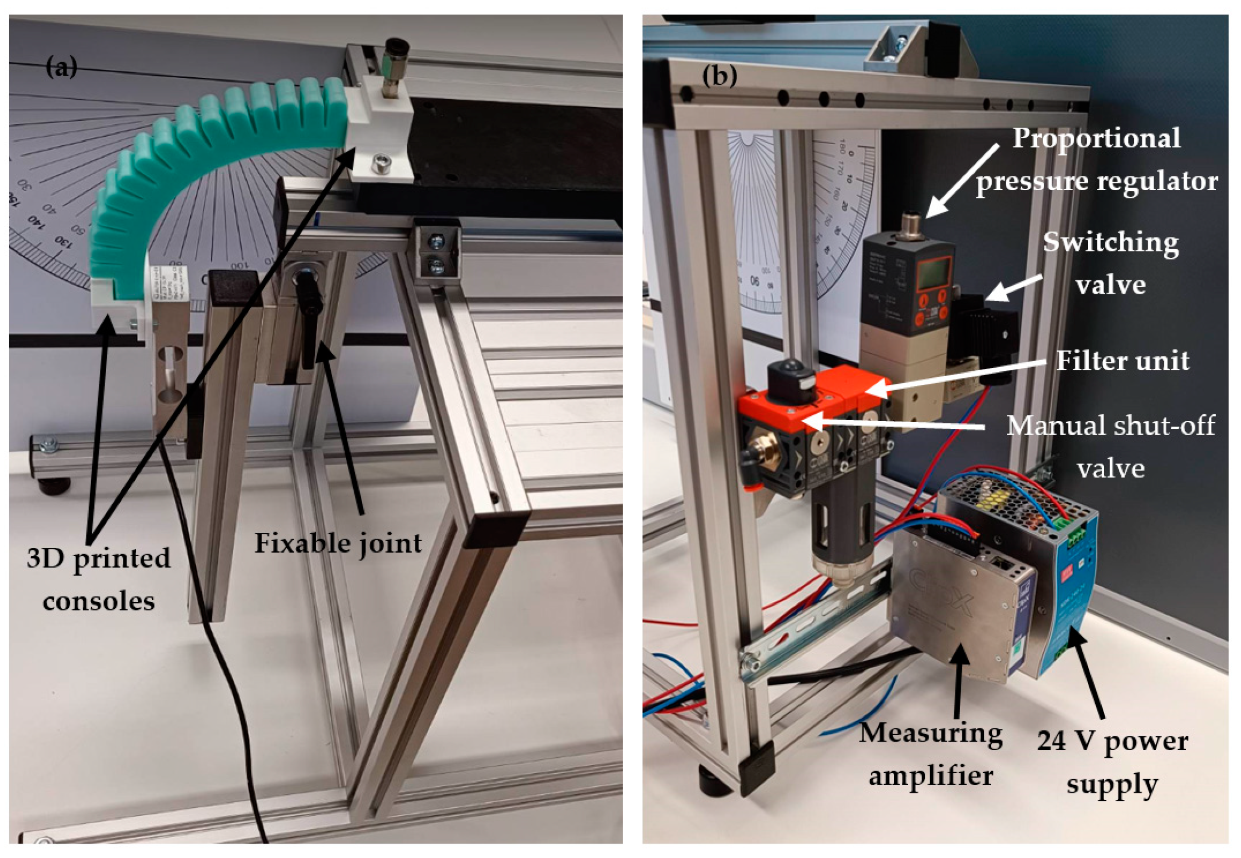
A platform was developed for the measurement of actuator properties, which can be seen in Figure 5. The design of the platform allows to investigate the movement and bending properties of the actuators.
Suitable angle values can be set and fixed on the platform through a fixable joint point. Structural profiles and 3D printed consoles were mounted on both sides of the joint to make it easy to connect any sensor or measuring unit, as shown in Figure 5a. A protractor was also installed to provide the appropriate angle settings during measurements. The operating and data collection units were placed on the back of the platform. The compressed air system includes a METALWORK REG Syntesi®SY1 1/8” manual shut-off valve, a METALWORK DEP SY1 filter unit, a METALWORK EB 80 proportional pressure regulator that allows pressure to be adjusted with kPa accuracy, and finally a METALWORK PLT-10 3/2 electrically operated switching valve. The signals from the measuring cell are processed using an HBM ClipX measuring amplifier and the data is transmitted to the computer. The air system and the measuring amplifier are powered by a MEAN WELL NDR-240-24 type power supply with 24V DC voltage, as shown in Figure 5b.
3. Results
3.1. Force Measurement with Externally Attachable Inter-Chamber Plates
One of the main characteristics of soft actuators is the amount of force they can generate during their bending motion. The aim of the measurement is to investigate the effect of plates on the behavior of the actuator at different angle positions and pressure values. During the measurement, both sides of the actuator were fixed, thanks to the pre-designed units. In most wearable applications, both ends are also fixed for optimal efficiency, and hence this measurement method was chosen. A rotated right-handed coordinate system was assigned to the actuator, which enables the interpretation of the directionality of the results obtained from the measurements. Z-axis forces compressing the cell will have a positive sign, while tensile forces will have a negative sign. In this measurement phase, the magnitude of the force in the z-axis direction was examined. For the measurement, a SAUTER CP 10-3P1 force sensor cell with a maximum load capacity of 100 N was used, and its signal was processed and collected using an HBM ClipX signal amplifier.
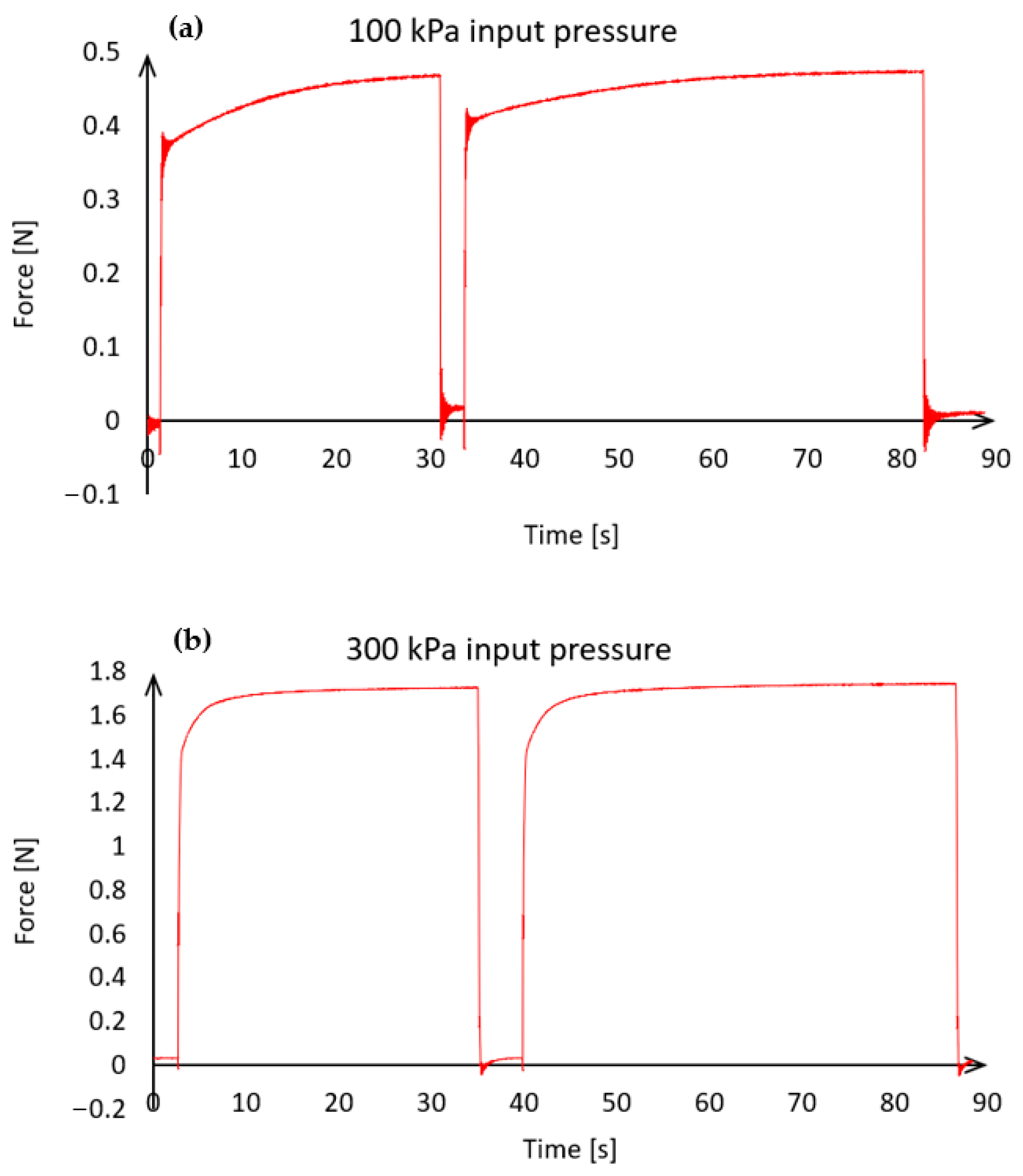
Before the first measurements were taken, the influence of the actuator’s elasticity and the filling of the chambers with high-pressure air was examined. The actuator was subjected to different pressure values (maximum 300 kPa), and it was observed that at a certain pressure, the maximum force does not immediately occur (Figure 6).
The actuator responds immediately to the input pressure, however, the force varies as a function of time. The development of the appropriate force magnitude could take up to 30 s at low pressure (Figure 6a). At a higher operating pressure (300 kPa), the force that can be considered constant builds up faster, in about 10 s (Figure 6b). The aim of this study is to determine the magnitude of the force in a steady state by inserting plates of different sizes. Therefore, even at low pressure values, the maximum force must be allowed to build up. Each measurement result was therefore recorded 30 s after the pressure signal was issued in order to always achieve a steady state for data acquisition.
Placing plates between the chambers modifies the resting state shape of the actuator, as shown in Figure 4. Plates with thicknesses of 0.5 mm and 1 mm cause only a small deformation, while the plate with the precise size of 1.5 mm and the oversized 2 mm plate significantly affect the resting deflection of the actuator. During the measurement, the forces resulting from these shape changes was not considered, as the measurements only investigated the effects caused by compressed air.
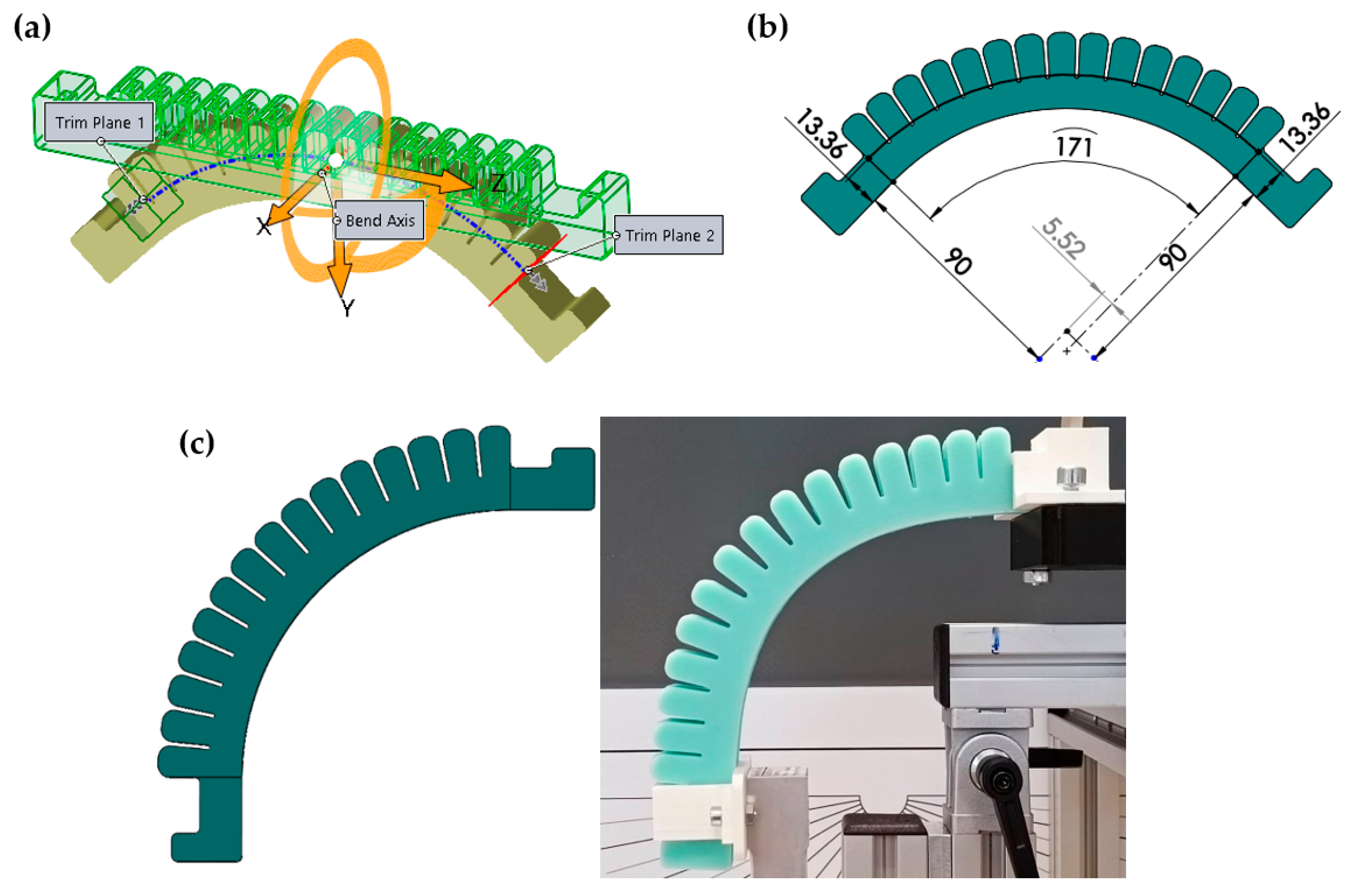
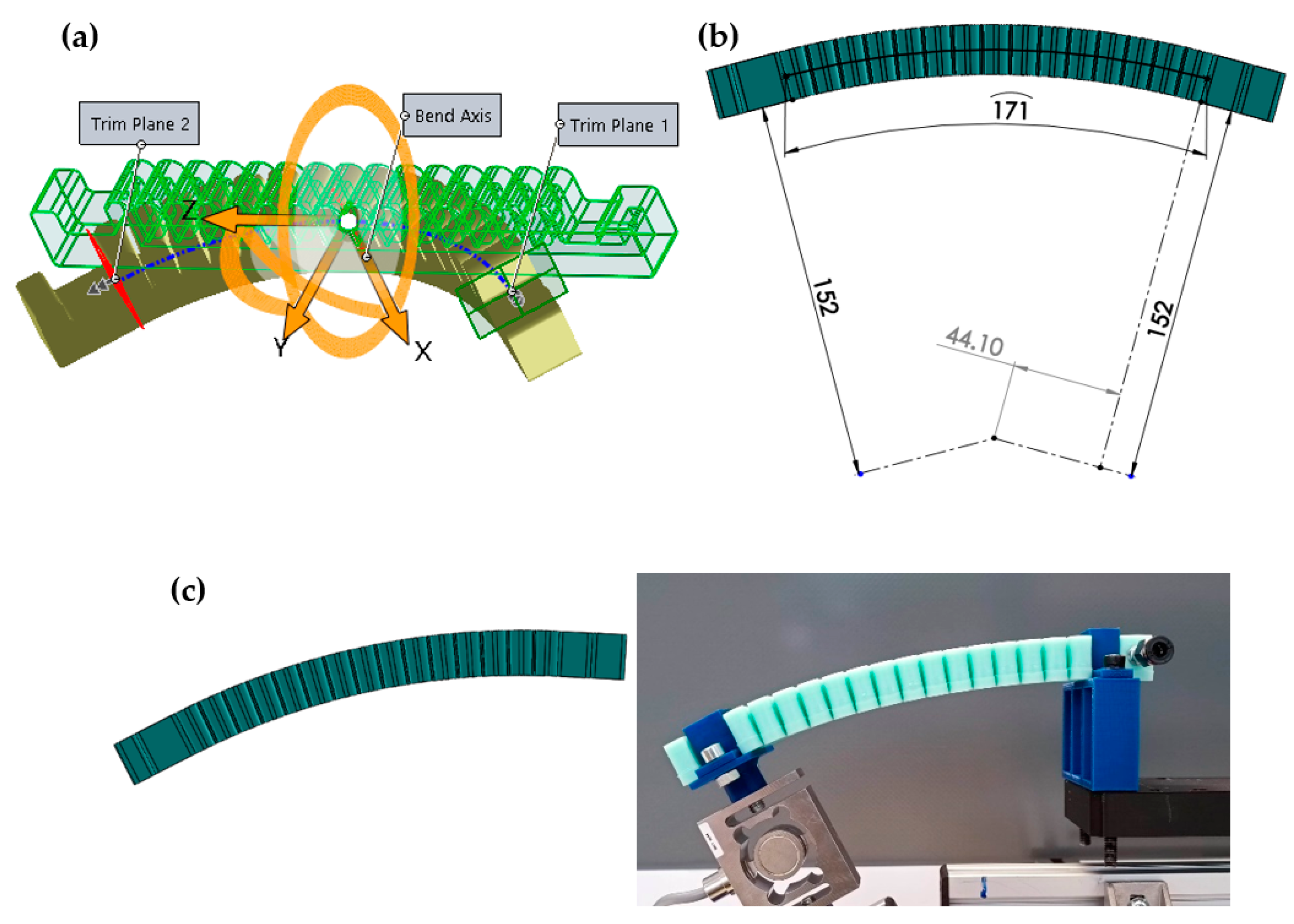
The actuator was measured at various fixed angular positions, from 0° to 120° with 30° increments; 120° is already a significant value in terms of displacement for most wearable applications, which is why it was determined as the extreme value. The necessary data for proper positioning of the actuator was determined using the Flex feature of the SOLIDWORKS 2016 3D design program, as shown in Figure 7.
The neutral plane is determined via the program according to the bending plane, using the 3D model of the actuator, taking into account the geometry of the actuator. The height of this neutral plane was determined to be 13.36 mm from the bottom of the actuator. The actuator was clamped on both sides during the measurement, therefore, trim planes also had to be determined for accurate results (Figure 7a). These were located 30 mm from the end of the actuator, so the size of the bending section was 171 mm. The additional units on the measurement platform, on which the actuator and the measuring cell are fixed, have a height of 90 mm. With this data, the distances from the pivot point can be determined (Figure 7b) which is necessary to measure the actuator in its ideal bending state for every angular position and thus make the measurement process repeatable (Figure 7c). The method presented in Figure 7b determined the distance of trimming plane (the plane where the chambers of the actuator begin) from the hinge point for every measuring angle. The results are presented in Table 3.
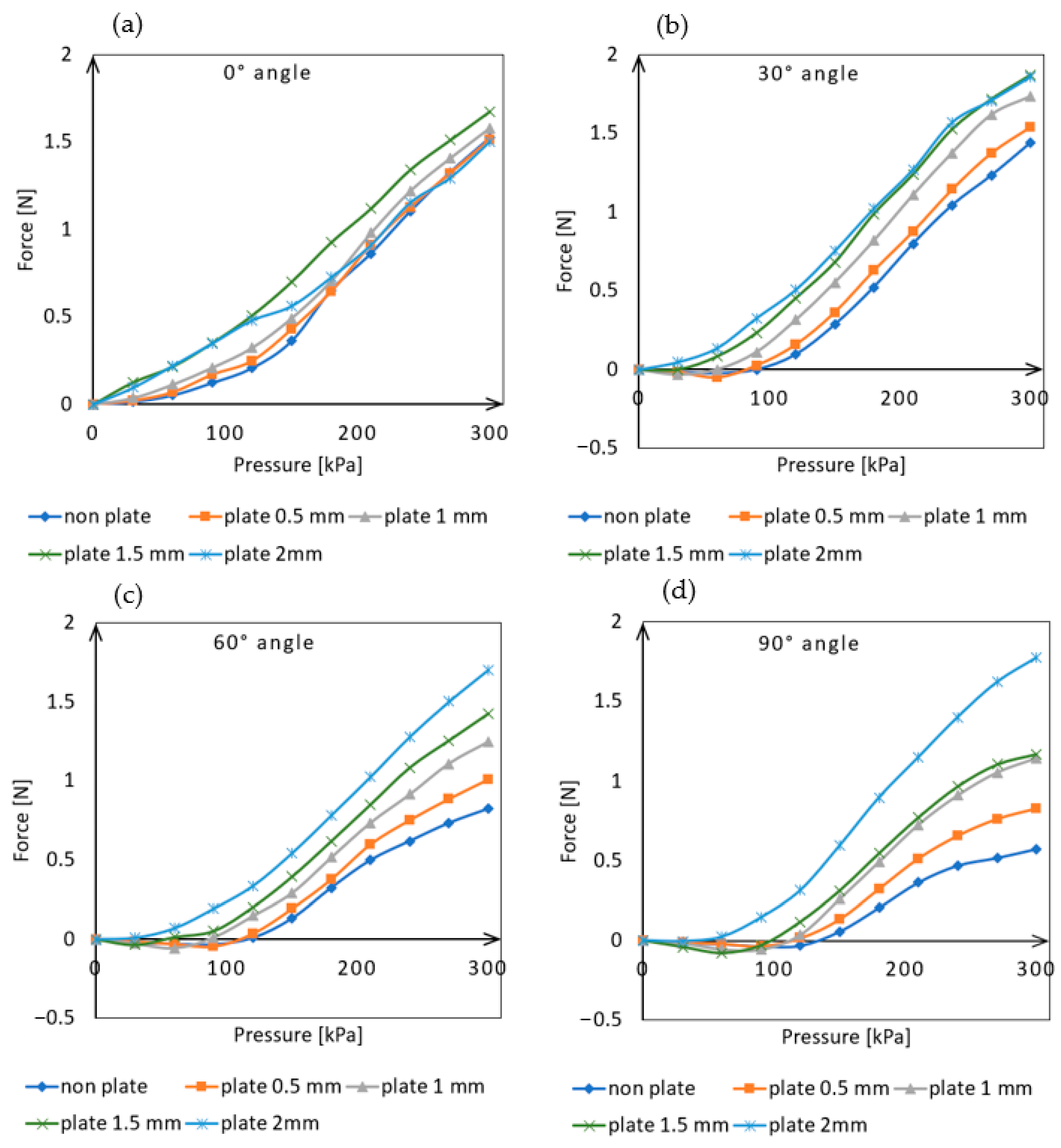
The measurement of the actuator was carried out at five different angular positions ranging from 0° to 120° with 30° increments, as well as at different input pressures ranging from 0 kPa up to the maximum of 300 kPa with 30 kPa increments. At each angular position, the measurements were performed with the external placement of the different thickness inter-chamber plates. Each measurement was repeated five times and the average of the obtained results is illustrated in Figure 8.
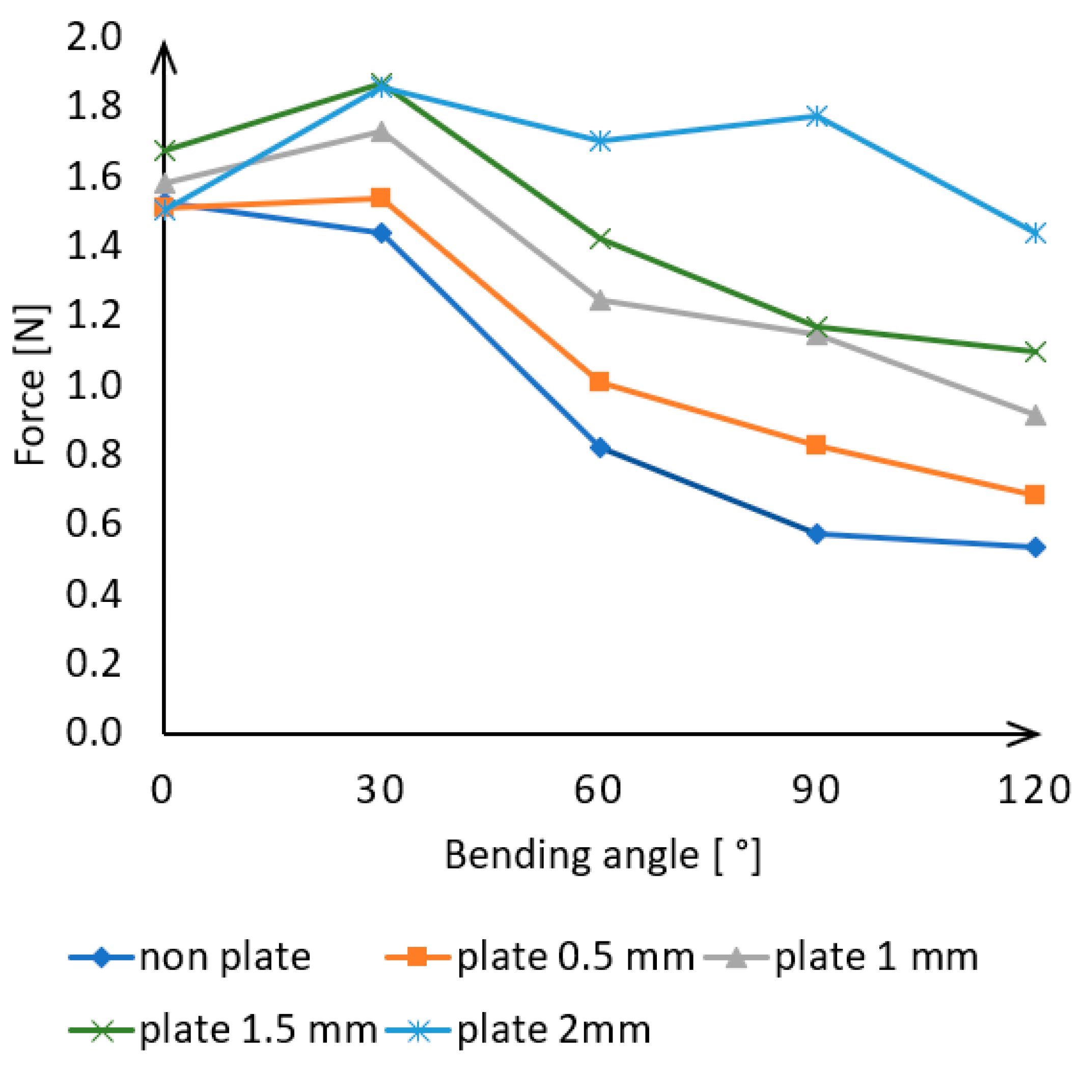
As can be seen in Figure 8a, there is no significant difference in the actuator force exertion between the different-sized plates when positioned at a 0° angle. Without a plate and with the thickest 2 mm plate, the actuator was able to exert approximately 1.5 N of force on the load cell.
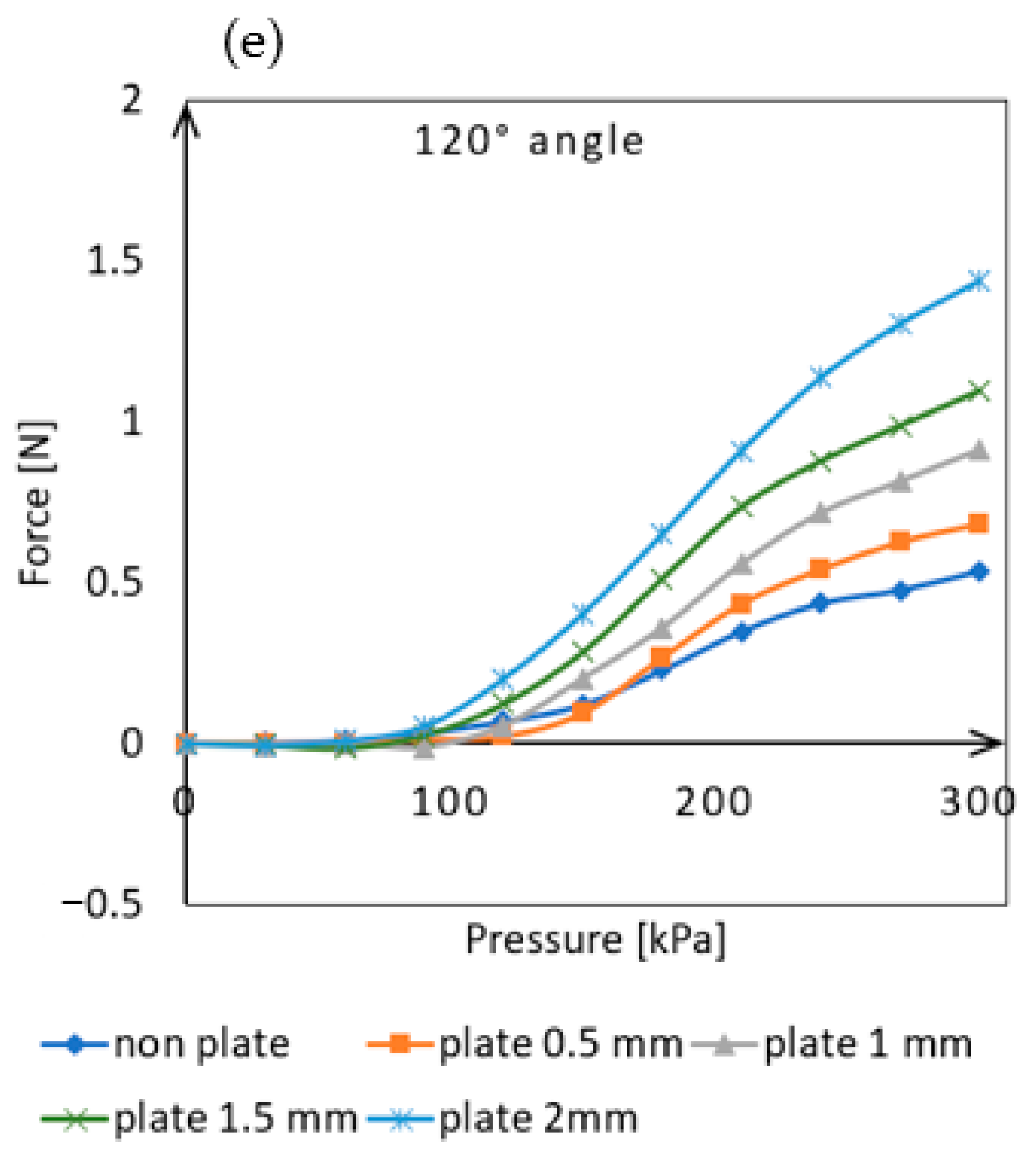
As the angle value increased (Figure 8b), the plates placed between the chambers increases bending performance, as the actuator is able to exert greater force at lower pressure levels as compared to the absence of plates. From a 60° angle position (Figure 8c), it can be observed that the curves are clearly separated from each other and the force exertion increases with increasing plate thickness at a given pressure. The measurements taken at a 90° angle position (Figure 8d) showed the largest differences in force exertion. In this position, the plate-less actuator was capable of exerting 0.57 N of force, while the one equipped with a 0.5 mm plate produced 0.82 N, 1 mm plate produced 1.14 N, 1.5 mm plate produced 1.17 N, and the one with a 2 mm plate produced 1.77 N of force. The actuator was able to exert three times the force with the help of the 2 mm plates compared to the plate-less one. Even at the largest tested bending angle (120°), significant differences were observed in the force exerted by the actuators equipped with different plates (Figure 8e). In this position, the plate-less actuator was capable of exerting 0.53 N of force, while the one equipped with a 0.5 mm plate produced 0.68 N, 1 mm plate produced 0.91 N, 1.5 mm plate produced 1.09 N, and the one with a 2 mm plate produced 1.43 N of force. The results show that even the thinnest plate could produce a significant increase in force, but the best performance was achieved with the 2 mm thick plate, which showed more than a two-and-a-half times increase in force compared to the plate-less version.
As shown in Figure 4c, even the accurately sized 1.5 mm thick plates cause significant resting deformation in the actuator. This may be due to manufacturing inaccuracies and shrinkage during the solidification of the silicone rubber. However, the smallest 0.5 mm thick plate does not significantly affect resting deformation. Measurements have shown that even with this plate size, the magnitude of the exerted force can be increased. At a 90° angle of deflection (Figure 8d), the actuator equipped with the plate was able to exert 0.83 N of force on the load cell, compared to only 0.57 N without it. This represents an increase of 145%.
Compared to the results measured at a maximum pressure of 300 kPa, it can be seen on Figure 9 that the force exerted is nearly the same for each plate thickness at 0° and 30° angles.
As the angle increases to 60°, 90°, and 120°, the force value continuously decreases. For the actuator without plates, this represents a 65% decrease, while for 0.5 mm, 1 mm, and 1.5 mm plates, it represents a decrease of 55%, 43%, and 35%, respectively, compared to the initial force. The 2 mm plate produced nearly the same force at every angle and only showed a 5% decrease in force at the 120°measurement.
3.2. External Inter-Chamber Plates Effect on Passive Lateral Bending
The insertion of plates between the chambers is not only influenced by the active deflection of the actuator, as the elimination of gaps also limits the flexibility of the device. An important feature of wearable applications is that the actuators are flexible and bendable in inactive status. The insertion of solid elements between the chambers affects this property, so the force determined was required to bend the device along the x-axis of a rotated right-handed coordinate system attached to the end of the actuator for plates of different thicknesses. For the measurement, an HBM S9M-type load cell was used with a capacity of 2 kN and an HBM ClipX measuring amplifier. The compressive forces applied to the measuring cell are assigned a positive sign, while the tensile forces are assigned a negative sign during the measurement process.
During the measurement, the bending angle varied from 0° to 50° in 10° increments, as a 50° sideways deflection is considered significant for wearable applications. The necessary data for proper positioning of the actuator was determined using the Flex feature of the SOLIDWORKS 2016 3D design program (Figure 10a).
The program determines the neutral plane based on the bending plane using the 3D model of the actuator, considering the geometry of the actuator. The height of this neutral plane was found to be 10 mm from the bottom of the actuator. The actuator was clamped on both sides during the measurement, therefore trim planes also had to be determined for accurate results (Figure 10a). These were located 30 mm from the end of the actuator, so the size of the bending section was 171 mm. The additional units have a height of 152 mm. Based on this information, the distances can be determined from the pivot point (Figure 10b) that are necessary to measure the actuator in its ideal deflection state at every angle (Figure 10c), and thus make the results repeatable. This method was used to determine the distances of the trimming planes from the pivot point for every angle, and the results are shown in Table 4.
Each angular position was measured with the placement of plates of varying thicknesses, and each measurement was performed five times. The average of the results obtained is shown in Figure 11.
The initial values show a positive force direction, as in this position, the force cell was subjected to a compressive force due to the deformation caused by the gravitational force of the actuator. This compressive force gradually decreased with increasing angle, as the actuator can only perform limited deformation in this direction due to its elasticity. It is evident that the measurement results without the plate and the measurements with the 0.5 mm plate closely follow each other, with the required force for deformation being almost identical in both cases. Therefore, the thinnest plate has little effect on lateral bending.
For other plates, it is apparent that greater force was required at the given angular positions. However, the deformation for these plates did not reach 50°, as certain deformations occurred during bending that were not in the intended bending direction. Deformations occur on the actuator because at larger angular positions, the walls of the chambers come into contact, leaving no room for undisturbed lateral bending. Inserting plates allows this state to be achieved at smaller angular positions due to the limitation of the distance between the chambers. If the actuator is forced into an angular position that the given plate thickness cannot handle, bending in directions other than lateral occurs. This leads to the actuator’s torsion (Figure 12).
For the larger plate thicknesses, the measurement continued until the appearance of these deformations, up to 40° for 1 mm, 30° for 1.5 mm, and 20° for 2 mm. As the plate thickness increased, the passive lateral bending capability of the actuator decreased significantly.
4. Discussion
The experiments conducted in this study demonstrated that the exerted force of soft actuators made entirely of elastic material can be increased by retroactively attaching external solid elements. By placing 3D-printed plates to fill the space between the chambers, the actuator produced higher forces in every angular position and pressure level during measurements. The greatest increase was achieved with the 2 mm thick plate. At a maximum pressure of 300 kPa and a 90-degree angle, a 310% force increase was achieved. The measurement results indicate that the 2 mm thick inter-chamber plate improved the actuator’s force output performance at almost every angular position and pressure level.
However, it is also evident that even the thinnest plate has a positive effect on the actuator’s performance. At a 90-degree angle of bending, it increased force by 145%.
Further research is required to investigate how changes in angle affect the actuator’s force output at maximum input pressure. As the actuator bends at a greater angle, it can exert less force because its internal stress increases. The measurement results show that while the force reduction is continuous for thinner plates, it is relatively small for the 2 mm plate. At a pressure of 300 kPa, the actuator without plates could only produce 45% of the force exerted at 0 degrees when it was bent to 120 degrees. In contrast, the version equipped with the 2 mm plate still achieved 95% of the force.
The external Inter-chamber plates can significantly affect the actuator’s lateral movement since they eliminate the gap between the chambers, which is mostly due to their flexibility. The measurement results showed that while the thinnest 0.5 mm plate had minimal impact on these movements, the thicker ones significantly restricted them. While the plate-less actuator could produce a 50-degree bend, the thickest plate-equipped actuator could only bend up to 20 degrees without any unexpected deformation occurring.
The data clearly show that there is no significant difference between the results of the side bending measurements of the actuator with no plate and the one equipped with a 0.5 mm thick plate. This suggests that if significant passive lateral movements can be expected during use, it is advisable to use thinner inter-chamber plates.
5. Conclusions
The possibility of increasing the output force of a soft actuator made entirely of elastic material was investigated in this study, by using external, retrofittable inter-chamber plates that could be applied to any similar actuator design. The application of the external plates had a positive effect on the output force, and even with the thinnest plate, a significant difference was observed.
The measurements also examined how the plates influence the passive behavior of the actuator, as elasticity is a very important property of soft actuators, especially in wearable applications. The measurements showed that the insertion of the plates between the chambers significantly affects their lateral bending ability.
In the future, an interesting topic could be how these plates work in actuators that contain non-extensible materials in their layers for better performance.
Some aspects of this research need further development or additions, such as optimizing the applied actuator structure, performing simulation measurements, and verifying the effects of the elements securing the plates.
The application of external inter-chamber plates used in this study provides a new concept for pneumatic actuators, where the output force of easily manufactured fully elastic actuators can be increased without any internal intervention or modification.
Author Contributions
Conceptualization, A.M. and J.S.; writing—review and editing, A.M. and J.S. All authors have read and agreed to the published version of the manuscript.
Funding
This research received no external funding.
Data Availability Statement
Data sharing is not applicable to this article.
Conflicts of Interest
The authors declare no conflict of interest.
References
- Wei, Y.; Jia, D. Research on Robotic Arm Movement Grasping System Based on MYO. J. Phys. Conf. Ser. 2021, 1754, 012173. [Google Scholar] [CrossRef]
- Giberti, H.; Abbattista, T.; Carnevale, M.; Giagu, L.; Cristini, F. A Methodology for Flexible Implementation of Collaborative Robots in Smart Manufacturing Systems. Robotics 2022, 11, 9. [Google Scholar] [CrossRef]
- Matheson, E.; Minto, R.; Zampieri, E.G.G.; Faccio, M.; Rosati, G. Human–Robot Collaboration in Manufacturing Applications: A Review. Robotics 2019, 8, 100. [Google Scholar] [CrossRef]
- Trivedi, D.; Rahn, C.D.; Kier, W.M.; Walker, I.D. Soft robotics: Biological inspiration, state of the art, and future research. Appl. Bionics Biomech. 2008, 5, 99–117. [Google Scholar] [CrossRef]
- Rus, D.; Tolley, M.T. Design, fabrication and control of soft robots. Nature 2015, 521, 467–475. [Google Scholar] [CrossRef]
- Chou, C.-P.; Hannaford, B.; Hannaford, B. Measurement and modeling of McKibben pneumatic artificial muscles. IEEE Trans Robot. Autom 1996, 12, 90–102. [Google Scholar] [CrossRef]
- Sárosi, J.; Bíró, I.; Nemeth, J.; Cveticanin, L. Dynamic modeling of a pneumatic muscle actuator with two-direction motion. Mech. Mach. Theory 2015, 85, 25–34. [Google Scholar] [CrossRef]
- Marchese, A.D.; Katzschmann, R.K.; Rus, D. A Recipe for Soft Fluidic Elastomer Robots. Soft Robot. 2015, 2, 7–25. [Google Scholar] [CrossRef]
- Youn, J.-H.; Jeong, S.M.; Hwang, G.; Kim, H.; Hyeon, K.; Kyung, K.-U. Dielectric Elastomer Actuator for Soft Robotics Applications and Challenges. Appl. Sci. 2020, 10, 640. [Google Scholar] [CrossRef]
- Tse, Z.T.H.; Chen, Y.; Hovet, S.; Ren, H.; Cleary, K.; Xu, S.; Wood, B.; Monfaredi, R. Soft Robotics in Medical Applications. J Med. Robot. Res 2018, 3, 1841006. [Google Scholar] [CrossRef]
- Ashuri, T.; Armani, A.; Hamidi, R.J.; Hamidi, R.J.; Reasnor, T.; Ahmadi, S.; Iqbal, K. Biomedical soft robots: Current status and perspective. Biomed. Eng. Lett. 2020, 10, 369–385. [Google Scholar] [CrossRef]
- Deimel, R.; Brock, O. A novel type of compliant and underactuated robotic hand for dexterous grasping. Int. J. Robot. Res. 2016, 35, 161–185. [Google Scholar] [CrossRef]
- Suzumori, K.; Iikura, S.; Tanaka, H. Applying a flexible microactuator to robotic mechanisms. IEEE Control Syst. Mag. 1992, 12, 21–27. [Google Scholar] [CrossRef]
- Onal, C.D.; Marchese, A.D.; Rus, D. autonomous soft robotic fish capable of escape maneuvers using fluidic elastomer actuators. Soft Robot. 2014, 1, 75–87. [Google Scholar] [CrossRef]
- Tolley, M.T.; Shepherd, R.F.; Mosadegh, B.; Galloway, K.C.; Wehner, M.; Karpelson, M.; Wood, R.J.; Whitesides, G.M. Resilient, untethered soft robot. Soft Robot. 2015, 1, 213–223. [Google Scholar] [CrossRef]
- Verl, A.; Albu-Schffer, A.; Brock, O.; Raatz, A. Soft Robotics: Transferring Theory to Application; Springer: Berlin/Heidelberg, Germany, 2015. [Google Scholar]
- Chiaradia, D.; Xiloyannis, M.; Antuvan, C.W.; Frisoli, A.; Masia, L. Design and embedded control of a soft elbow exosuit. Int. Conf. Soft Robot. 2018, 565–571. [Google Scholar] [CrossRef]
- Park, S.-J.; Park, C.H. Suit-type Wearable Robot Powered by Shape-memory-alloy-based Fabric Muscle. Sci. Rep. 2019, 9, 9157. [Google Scholar] [CrossRef]
- Liu, Z.; Yin, X.; Peng, K.; Wang, X.; Chen, Q. Soft pneumatic actuators adapted in multiple environments: A novel fuzzy cascade strategy for the dynamics control with hysteresis compensation. Mechatronics 2022, 84, 102797. [Google Scholar] [CrossRef]
- Xavier, M.S.; Tawk, C.; Zolfagharian, A.; Pinskier, J.; Howard, D.; Young, T.; Lai, J.; Harrison, S.M.; Yong, Y.K.; Bodaghi, M.; et al. Soft Pneumatic Actuators: A Review of Design, Fabrication, Modeling, Sensing, Control and Applications. IEEE Access 2022, 10, 59442–59485. [Google Scholar] [CrossRef]
- Miriyev, A.; Stack, K.W.; Lipson, H. Soft material for soft actuators. Nat. Commun. 2017, 8, 596. [Google Scholar] [CrossRef] [PubMed]
- Wang, J.; Jue, W. Alex Chortos Control Strategies for Soft Robot Systems. Adv. Intell. Syst. 2022, 4, 2100165. [Google Scholar] [CrossRef]
- Chen, W.; Xiong, C.; Liu, C.; Peimin, L.; Chen, Y. Fabrication and dynamic modeling of bidirectional bending soft actuator integrated with optical waveguide curvature sensor. Soft Robot. 2019, 6, 495–506. [Google Scholar] [CrossRef] [PubMed]
- Hu, W.; Mutlu, R.; Li, W.; Alici, G. A Structural Optimisation Method for a Soft Pneumatic Actuator. Robotics 2018, 7, 24. [Google Scholar] [CrossRef]
- Paez, L.; Agarwal, G.; Paik, J. Design and Analysis of a Soft Pneumatic Actuator with Origami Shell Reinforcement. Soft Robot. 2016, 3, 109–119. [Google Scholar] [CrossRef]
- Polygerinos, P.; Wang, Z.; Overvelde, J.T.B.; Galloway, K.C.; Wood, R.J.; Bertoldi, K.; Walsh, C.J. Modeling of Soft Fiber-Reinforced Bending Actuators. IEEE Trans. Robot. 2015, 31, 778–789. [Google Scholar] [CrossRef]
- Yap, H.K.; Ang, B.W.K.; Lim, J.H.; Goh, J.C.H.; Yeow, C.-H. A fabric-regulated soft robotic glove with user intent detection using EMG and RFID for hand assistive application. In Proceedings of the 2016 IEEE International Conference on Robotics and Automation (ICRA), Stockholm, Sweden, 16–21 May 2016; pp. 3537–3542. [Google Scholar] [CrossRef]
- Mosadegh, B.; Polygerinos, P.; Keplinger, C.; Wennstedt, S.W.; Shepherd, R.; Gupta, U.; Shim, J.; Bertoldi, K.; Walsh, C.J.; Whitesides, G.M. Pneumatic Networks for Soft Robotics that Actuate Rapidly. Adv. Funct. Mater. 2014, 24, 2163–2170. [Google Scholar] [CrossRef]
- Jing, X.; Chen, S.; Zhang, C.; Xie, F. Increasing Bending Performance of Soft Actuator by Silicon Rubbers of Multiple Hardness. Machines 2022, 10, 272. [Google Scholar] [CrossRef]
- Chen, Y.; Le, S.; Tan, Q.C.; Lau, O.; Wan, F.; Song, C. A reconfigurable hybrid actuator with rigid and soft components. In Proceedings of the 2017 IEEE international conference on robotics and automation (ICRA), Singapore, 29 May–3 June 2017; pp. 58–63. [Google Scholar] [CrossRef]
- Galloway, K.C.; Polygerinos, P.; Walsh, C.J.; Wood, R.J. Mechanically programmable bend radius for fiber-reinforced soft actuators. In Proceedings of the IEEE International Conference on Advanced Robotics, Tainan, Taiwan, 31 May–2 June 2013; pp. 1–6. [Google Scholar] [CrossRef]
- Sun, Z.; Guo, Z.; Wei, T. Design of wearable hand rehabilitation glove with soft hoop-reinforced pneumatic actuator. J. Cent. South Univ. 2019, 26, 106–119. [Google Scholar] [CrossRef]
- Zhu, L.; Wang, F.; Liu, S.; Tian, Y.; Zhang, D. Modeling and Analysis of Soft Pneumatic Network Bending Actuators. IEEE-ASME Trans. Mechatron. 2020, 26, 2195–2203. [Google Scholar] [CrossRef]
Figure 1.
Structure of the soft pneumatic actuator. The values shown in the figure are given in [mm]. The material of the actuator is Mold Max 40 casting silicone.
Figure 1.
Structure of the soft pneumatic actuator. The values shown in the figure are given in [mm]. The material of the actuator is Mold Max 40 casting silicone.

Figure 2.
Manufacturing process of the soft actuator.

Figure 3.
Bending motion sequence under pressurized air: (a) 0 kPa, (b) 50 kPa, (c) 100 kPa, (d) 150 kPa, (e) 200 kPa, (f) 300 kPa.
Figure 3.
Bending motion sequence under pressurized air: (a) 0 kPa, (b) 50 kPa, (c) 100 kPa, (d) 150 kPa, (e) 200 kPa, (f) 300 kPa.

Figure 4.
Externally attachable inter-chamber plates: (a) Structure of inter-chamber plates. The values shown in the figure are given in [mm], (b) Fabrication of the plates with 3D printer, (c) 0.5 mm thick plates placed on the actuator, (d) 1 mm thick plates placed on the actuator, (e) 1.5 mm thick plates placed on the actuator, (f) 2 mm thick plates placed on the actuator.

Figure 5.
The test platform and experimental setting: (a) The front of the testing device with an adjustable and lockable hinge, (b) operating and data collection units.
Figure 5.
The test platform and experimental setting: (a) The front of the testing device with an adjustable and lockable hinge, (b) operating and data collection units.

Figure 6.
The influence of the elasticity of a soft actuator on force generation without plates: (a) The magnitude of the exerted force over time at 150 kPa input pressure, (b) The magnitude of the exerted force over time at 300 kPa input pressure.
Figure 6.
The influence of the elasticity of a soft actuator on force generation without plates: (a) The magnitude of the exerted force over time at 150 kPa input pressure, (b) The magnitude of the exerted force over time at 300 kPa input pressure.

Figure 7.
Determination of the data required to create an ideal bending curve for measurements: (a) 90 ° bending curve modeling on the soft actuator in SOLIDWORKS 2016, (b) Determining the distance from the hinge point required to create an ideal bending curve, (c) Comparison of modeled bending and actual bending.

Figure 8.
Actuator force measurement data result: (a) Measurement results at 0° angle position, (b) Measurement results at 30° angle position, (c) Measurement results at 60° angle position, (d) Measurement results at 90° angle position, (e) Measurement results at 120° angle position.
Figure 8.
Actuator force measurement data result: (a) Measurement results at 0° angle position, (b) Measurement results at 30° angle position, (c) Measurement results at 60° angle position, (d) Measurement results at 90° angle position, (e) Measurement results at 120° angle position.


Figure 9.
Actuator force measurement data results for each angle examined.

Figure 10.
Determination of the data required to create an ideal bending curve for passive bending measurements: (a) 30 ° side bending curve modeling on the soft actuator in SOLIDWORKS 2016, (b) Determining the distance from the hinge point required to create an ideal side bending curve, (c) Comparison of modeled side bending and actual bending.

Figure 11.
Force effects arising from lateral bending as a function of angular values.

Figure 12.
Non-intended deformation with 2 mm plates at 30°bending angle.


Table 1.
Main 3D printing values of the main and side molds.
| 3D Printer Manufacturing Features | Values |
|---|---|
| Nozzle diameter | 0.4 mm |
| Nozzle temperature | 210 °C |
| Object table temperature | 60 °C |
| Printing speed | 50 mm/s |
| Layer height | 0.2 mm |
| Outer layer number | 3 |
| Infill density | 30% |
Table 2.
Main 3D printing values of inter-chamber plates.
| 3D Printer Manufacturing Features | Values |
|---|---|
| Nozzle diameter | 0.4 mm |
| Nozzle temperature | 210 °C |
| Object table temperature | 60 °C |
| Printing speed | 0 mm/s |
| Layer height | 0.1 mm |
| Outer layer number | 2 |
| Infill density | 100% |
Table 3.
Data required for an ideal bending curve.
| Measuring Angle [°] | Trimming Pane Distance from Hinge Point [mm] |
|---|---|
| 30 | 59.81 |
| 60 | 34.6 |
| 90 | 5.52 |
| 120 | −37.61 |
Table 4.
Data required for an ideal side bending curve.
| Measuring Angle [°] | Trimming Pane Distance from Hinge Point [mm] |
|---|---|
| 10 | 71.54 |
| 20 | 57.81 |
| 30 | 44.1 |
| 40 | 30.19 |
| 50 | 15.83 |
Disclaimer/Publisher’s Note: The statements, opinions and data contained in all publications are solely those of the individual author(s) and contributor(s) and not of MDPI and/or the editor(s). MDPI and/or the editor(s) disclaim responsibility for any injury to people or property resulting from any ideas, methods, instructions or products referred to in the content. |
© 2023 by the authors. Licensee MDPI, Basel, Switzerland. This article is an open access article distributed under the terms and conditions of the Creative Commons Attribution (CC BY) license (https://creativecommons.org/licenses/by/4.0/).
Share and Cite
MDPI and ACS Style
Mészáros, A.; Sárosi, J. Increasing the Force Exertion of a Soft Actuator Using Externally Attachable Inter-Chamber Plates. Actuators 2023, 12, 222. https://doi.org/10.3390/act12060222
AMA Style
Mészáros A, Sárosi J. Increasing the Force Exertion of a Soft Actuator Using Externally Attachable Inter-Chamber Plates. Actuators. 2023; 12(6):222. https://doi.org/10.3390/act12060222
Chicago/Turabian StyleMészáros, Attila, and József Sárosi. 2023. "Increasing the Force Exertion of a Soft Actuator Using Externally Attachable Inter-Chamber Plates" Actuators 12, no. 6: 222. https://doi.org/10.3390/act12060222
Note that from the first issue of 2016, this journal uses article numbers instead of page numbers. See further details here.