Article

Design Optimization of a Miniaturized Pneumatic Artificial Muscle and Experimental Validation

by
Shakila Zabihollah
,
Seyed Alireza Moezi
and
Ramin Sedaghati
*
Department of Mechanical, Industrial and Aerospace Engineering, Concordia University, Montreal, QC H3G 1M8, Canada
*
Author to whom correspondence should be addressed.
Actuators 2023, 12(6), 221; https://doi.org/10.3390/act12060221
Submission received: 29 March 2023 / Revised: 11 May 2023 / Accepted: 22 May 2023 / Published: 25 May 2023
(This article belongs to the Section Miniaturized and Micro Actuators)

Abstract

:
Miniaturized pneumatic artificial muscles (MPAMs) are widely utilized in various applications due to their unique characteristics, such as a high power-to-weight ratio, flexibility, and compatibility with the human environment, as well as being compact enough to fit within small-scale mechanical systems. Maximizing the amount of force generated by these actuators while keeping their dimensions minimized can greatly affect their efficiency. In this study, a formal design optimization problem was formulated to identify optimal sizes of MPAMs while maximizing their blocked force as a novel approach to address the issue of low force outputs of these actuators. A force model for an MPAM including various correction terms was derived to better predict the response behavior of the actuator. The optimization results reveal that an MPAM with a bladder that has an outer diameter of 6 mm and a thickness of 0.7 mm, as well as a braid angle of 72 degrees, can produce up to almost 239 N of blocked force if the inlet pressure is increased to 600 kPa. An MPAM with optimal parameters was subsequently fabricated and experimentally tested to evaluate its quasi-static response behavior and to validate the theoretical optimization results. Experimental tests were conducted under a wide range of pressures (0–300 kPa) to evaluate the variation of the generated blocked force versus inlet pressure. The overall error between the simulation and the experimental blocked forces was found to be less than 10%. This study represents a significant contribution to the design optimization of MPAMs, and the resulting optimal design offers potential applications in various fields, from soft robots to medical devices.

1. Introduction

Pneumatic artificial muscles (PAMs) possess advantages such as a high power-to-weight ratio, flexibility, low fabrication costs, and the ability to replicate the actuation behavior of natural muscles. In addition, they exhibit natural compliance, low operating pressure, and excellent static performance, making them inherently safe for use in biorobotic systems that operate in close proximity to human beings [1,2]. PAMs have been a crucial component in a variety of biologically inspired robots, recovery devices, exoskeletons, and many other applications [3,4,5,6,7,8,9,10]. Several types of PAMs have emerged based on distinct design principles and applications. The literature has categorized these into four primary groups, namely braided muscles (also known as McKibben muscles), pleated muscles, netted muscles, and embedded muscles [11]. McKibben muscles, which are the most famous and widely used category of PAMs, were first introduced in the 1950s by Josef McKibben to be utilized in the areas of prosthetics and orthotics [12]. After a number of improvements in the structure and applications of these actuators, the Bridgestone Company began commercializing them in the 1980s [13]. At present, multiple corporations (namely Shadow Robot Company, Merlin Systems Corporation, Hitachi Medical Corporation, and Festo) produce and sell McKibben muscles on the market [14].
Recent advances in small-scale biorobotic systems have heightened the demand for the development of actuation systems that are power-efficient and capable of producing large amounts of force while being compact and light enough to fit within these miniaturized systems. To reduce the size and weight of the conventional types of PAMs, Park et al. [15] designed a PAM capable of detecting its contraction length through hyperelastic strain sensing with embedded microchannels containing a liquid conductor. This resulted in a system with no external measurement device of significant size. Wakimoto et al. [16] developed a smart McKibben actuator with an integrated pressure sensor using a conductive material for one of the braid fibers. By monitoring the conductive fiber’s electrical resistance, the pressure was calculated. The pressure could also be regulated by sending feedback to the pressure sensor. Another self-sensing PAM capable of measuring capacitance to determine the length of the actuator and, consequently, its deformation was designed by Kanno et al. [17], employing a dielectric elastomer sensor (DES). Fu et al. [18] presented a multisensory yarn for PAMs that can detect variations in force, displacement, and vertical pressure. The developed actuator was also tested in numerous applications to demonstrate its usefulness. To reduce the overall length and weight of the PAM while maintaining the optimum contraction, Carvalho et al. [19] designed innovative end fittings, resulting in a shorter overall length of the muscle. Miniaturized artificial muscles (MPAMs) are the smaller version of PAMs, with the same advantages but a much smaller size and weight, which is intriguing for miniaturized applications, including wearable hand exoskeletons [20], cardiac compression devices, and manipulation tools for minimally invasive surgery [21]. Lathrop et al. [22] conducted a study on several MPAMs featuring different dimensions to be employed in flexible instruments essential for minimally invasive surgery (MIS). The finger utilized in robotic hand prosthesis designed by Markus et al. [23] was actuated by MPAMs, with an initial diameter of 10 mm and a thickness of 1.8 mm, as an alternative to electrically driven actuators. Ashwin and Ghosal [24] presented an endoscopic end effector actuated by three MPAMs to manipulate a catheter tip to a specific location. However, fabrication and modeling challenges are increased for MPAMs due to their small size. It has been reported that these actuators have low force and contraction outputs [25,26]. Given the extent of the applications of MPAMs, it is of utmost importance to enhance their design and efficiency.
The performance evaluation of MPAMs and enhancement of their design begins with quantifying two principal parameters, namely the blocked force and free contraction. The blocked force is the amount of force generated by a PAM when its length is held constant at its initial free length, whereas free contraction is the state in which the PAM is pressured while not being constrained, thus producing no actuation force. The geometrical and material properties of these actuators greatly influence their generated blocked force and contraction. Previous experimental research studies have revealed that stiffer actuators (or braids) generate more work per cycle. Doumit and Leclair [27] developed and verified a stiffness model that took the geometry and friction factors into account. They conducted eccentric contraction tests using a tensile testing machine to evaluate the PAM’s passive behavior. They examined the bladder material, elongation speed, and initial pressure, and their stiffness model demonstrated remarkable accuracy in interpreting the nonlinear behavior of PAMs. The primary goal of creating such a model was to improve the functionality of PAM as passive elements in assistive technologies for human mobility. Salahuddin et al. [28] proposed a characterization approach for measuring the changes in force and displacement, as well as the free contraction, blocked force, and contraction, when a hydraulic McKibben muscle was externally loaded. Pillsbury et al. [29] studied the effect of bladder thickness and material on the important performance characteristics of a PAM; the results of their modeling and experiments showed that the blocked force and free contraction both decreased when the thickness of the bladder was increased. They later compared three bladder materials and found that the PAM made with a V-330 bladder showed the lowest amount of dead-band pressure while producing higher amounts of force [29]. Kothera et al. [30] carried out an experiment to investigate the effect of different geometrical parameters on the generated blocked force. It was conclusively demonstrated that the length of the PAM does not considerably affect the generated blocked force, while increasing the braid angle and diameter of the bladder increases the force produced by the actuator. The same effect was observed by Gentry et al. [31] and Joe et al. [32]. Sangrian et al. [33] proposed corrected force models for studying the effect of bladder stiffness, pressure, and length of a small hydraulic McKibben muscle, which used water or oil as the working fluid. They concluded that the blocked force and contraction strain decrease as the stiffness of the bladder increases. Therefore, developing a precise force model that enables a comprehensive investigation of the impacts of all key parameters on the force and contraction outputs of MPAMs is an essential prerequisite for enhancing their design.
In addition to developing an accurate force model, several efforts have been made to design improved small-scaled PAMs that exhibit superior force and contraction outputs. Previous research studies have reported that small-scale hydraulic actuators produce greater free contraction ratios [34] but at the expense of substantially higher actuation pressures, which could be hazardous in close proximity to humans. Sangrian et al. [33] used a finite-element model to design a novel type of PAM (ultralight hybrid PAM based on a bellow-type elastomeric skin) with a high contraction ratio and blocked force, as well as an enhanced axial stiffness. Yang et al. [35] developed a high-displacement PAM with increased contraction ratios made from soft material (textile or plastic). To extend the lifetime of straight-fiber artificial muscles (SFPAMs), the results of cyclic testing conducted by Tomori et al. [36] demonstrated that the failures should be focused on the rubber bladder, which can be repaired more easily than other components or can be constructed of self-healing elastomers. Xiao et al. [37] explored the multidirectional optimization of bending pneumatic artificial muscles to determine the optimized parameters that produce the maximized bending angle and force production. The developed BPAM could bend in eight directions, and the optimization findings showed that the bending angle and output force cannot both be optimized simultaneously, necessitating the selection of a compromise solution. To aid in human mobility, Diteesawat et al. [38] proposed optimal bubble artificial muscles (BAMs). In order to enhance the contraction a BAM, they optimized the length and radius of the actuator. Furthermore, by using materials with higher strength and the ability to withstand higher pressures for the fabrication of the BAM, the generated tension can also be increased. Lathrop et al. [39] designed an MPAM featuring a concentric dual chamber that delivers greater force output and contraction in comparison to typical MPAMs with similar dimensions, specifically for applications in MIS. However, the maximum force produced by their proposed actuator is only 15.25 N, representing an improvement of approximately 2 N over prior MPAMs. Kwon et al. [40] designed a flat PAM using rigid planes as external constraints to achieve a higher force and contraction ratio with minimal volume. Kim et al. [41] introduced a flat fabric PAM (ffPAM) capable of producing a maximum force of 118 N at 172 kPa and a maximum contraction ratio of 23% to be used in wearable applications. Nevertheless, the ffPAM exhibited a nonlinear force-contraction relationship, resulting in challenging length controls, and lacked significant free contraction. Thin McKibben muscles with diameters ranging between 1 and 3 mm have also been proposed to be utilized in miniaturized applications. Kurumaya et al. [42] introduced a multifilament muscle consisting of a bundle of thin McKibben muscles with outer diameters of 1.8 mm as an alternative to conventional PAMs. The proposed system could address the stiffness issues and the lack of deformation observed in typical PAMs. Later [43], they used 60 thin McKibben muscles to create a multifilament muscle for a musculoskeletal robot that could mimic the function of lower-limb muscles. Despite being used in various applications, thin McKibben muscles have some disadvantages when compared to MPAMs, including lower force output, reduced life span, reduced reliability, reduced range of motion, and increased sensitivity to external forces. Therefore, it is necessary to seek alternative solutions to the problems associated with MPAMs.
This study is motivated by the significance of MPAMs in various applications, specifically in the field of biorobotics. Previous studies have highlighted certain limitations in the force and contraction outputs of MPAMs, prompting further research. The aim of the present study is to formulate an accurate design optimization strategy and design an experiment to identify a miniaturized McKibben muscle capable of producing higher blocked force and free contraction compared to other MPAMs of the same size. Although some research has been conducted on the design optimization of various types of full-sized PAMs (SFPAM, BPAM, BAM, etc.), no literature is available regarding the design of optimum MPAMs with experimental validation to address the issue of their low force outputs while keeping their dimensions in the range of millimeters. Consequently, previous attempts have led to the production of bulky actuators that are not suitable for small-scale applications. This paper contributes to the field by deriving an accurate force model to identify key size parameters of MPAMs (in the range of millimeters) affecting their performance. This is the first study to focus exclusively on formulating a formal design optimization problem to maximize the generated blocked force of MPAMs within a given volume. The proposed design optimization for MPAMs improves upon the previous designs of miniaturized McKibben muscles, effectively filling the gap in maximizing force output while maintaining compactness. First, an analytical relation describing the generated force of the MPAM is derived based on the force balance equations. The force equation is then refined by adding correcting terms that consider the effects of the thickness of the bladder and properties of the braided sleeving. A design optimization is then formulated to maximize the blocked force as the objective function and the weight of the MPAM as the constraint. The optimized MPAM is fabricated utilizing commercially available materials and the identified optimized dimensions. The fabricated MPAM is subsequently tested to evaluate its force actuation performance under varied inlet pressure and to validate the simulation and optimization results. The MPAM is tested quasi-statically using an MTS servohydraulic machine across a range of inlet pressures (from 0 kPa to 300 kPa in increments of 20 kPa) to record the amount of blocked force under each pressure. The superior performance of the proposed optimally designed MPAM is finally verified through comparison with other MPAMs proposed in the literature. The results of this study provide valuable contributions to the design of efficient and compact MPAMs for use in a range of applications, namely prosthetic limbs, rehabilitation devices, surgical robots, and wearable medical devices such as wearable sensors and drug delivery systems. Such devices necessitate miniaturized actuators with high force outputs, and the optimized design of such actuators provided by this study meets this need.

2. Mathematical Modeling

Developing a precise force model plays an important role in the accurate prediction of the actuation behavior of PAMs. The force model should incorporate all geometrical parameters of the bladder and the braid that can considerably influence the performance of PAM. The important characteristics of the bladder, which is a hollow elastomeric cylinder, are its initial outer radius ( R 0 = D 0 / 2 ), initial length ( L 0 ), and initial thickness ( t 0 ), as shown in Figure 1. On the other hand, the braided sleeving is distinguished by its initial braid angle ( α o ), the length of one of its strands before being woven around the bladder ( B ), and the number of turns this strand makes from one end of the bladder to another ( N ) [44]. As shown in Figure 2, these parameters are related to each other as:
B = L o sin ( α o ) = L sin ( α )
N = B cos ( α o ) π D o = B cos ( α ) π D
tan α o = L 0 π D o N   and   tan α = L π D N
where R , L , and t are the instantaneous outer radius, length, and thickness of the bladder, respectively, and α is the instantaneous angle of the braid. Various force models have been proposed in several studies to relate these geometrical parameters to the outputs of PAMs. These models are either based on the force balance equilibrium or the energy balance principle [45,46]. There are also a number of correction terms that can be included in each model to establish more accurate results. These correction terms account for the nonlinearity of the bladder, the friction between the components of the actuator, the dead-band pressure, the energy stored in the braid, and the changes in length caused by the non-cylindrical tips of the PAM [30,45,47,48,49,50,51].

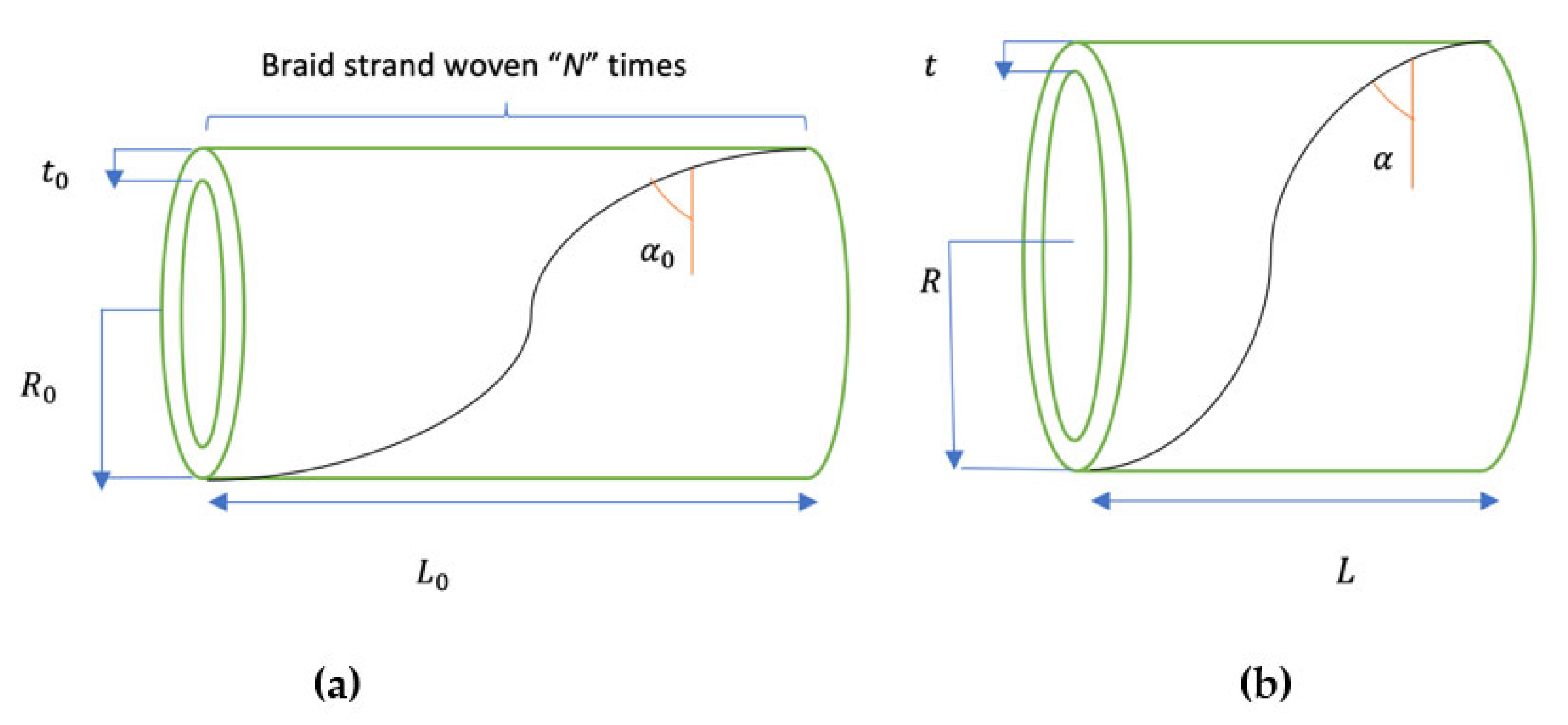
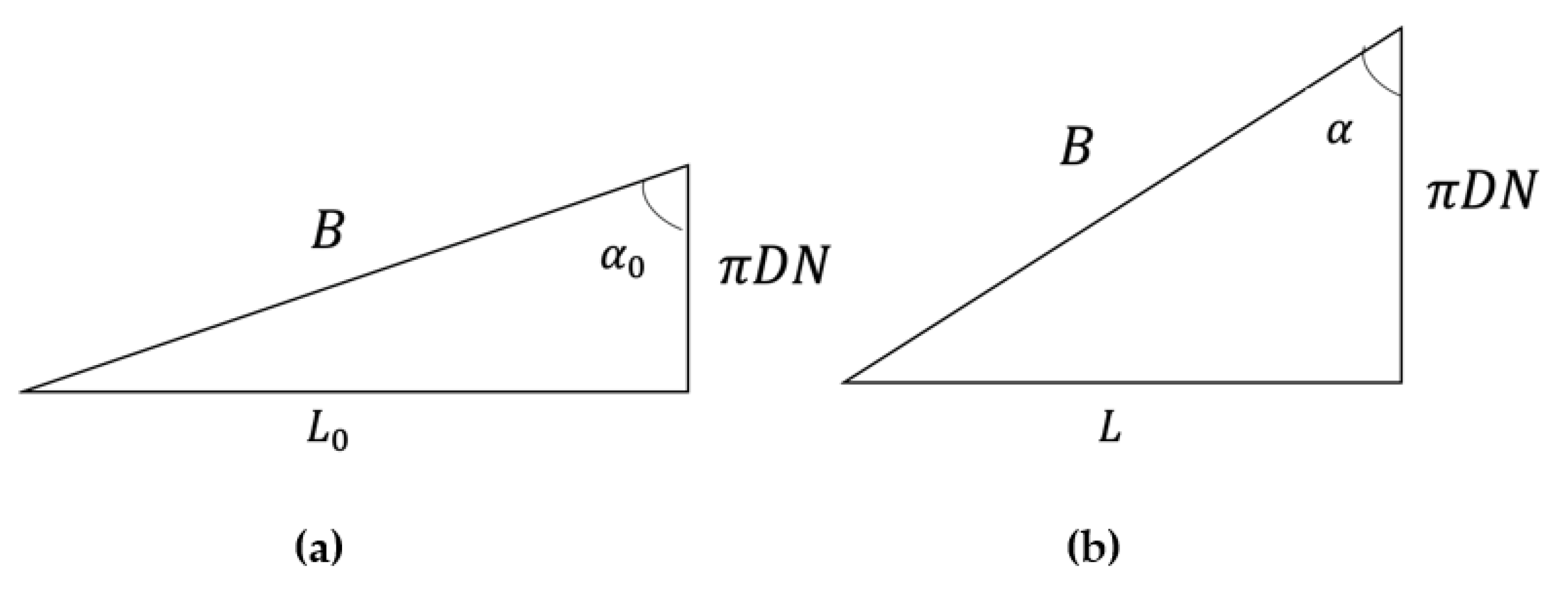
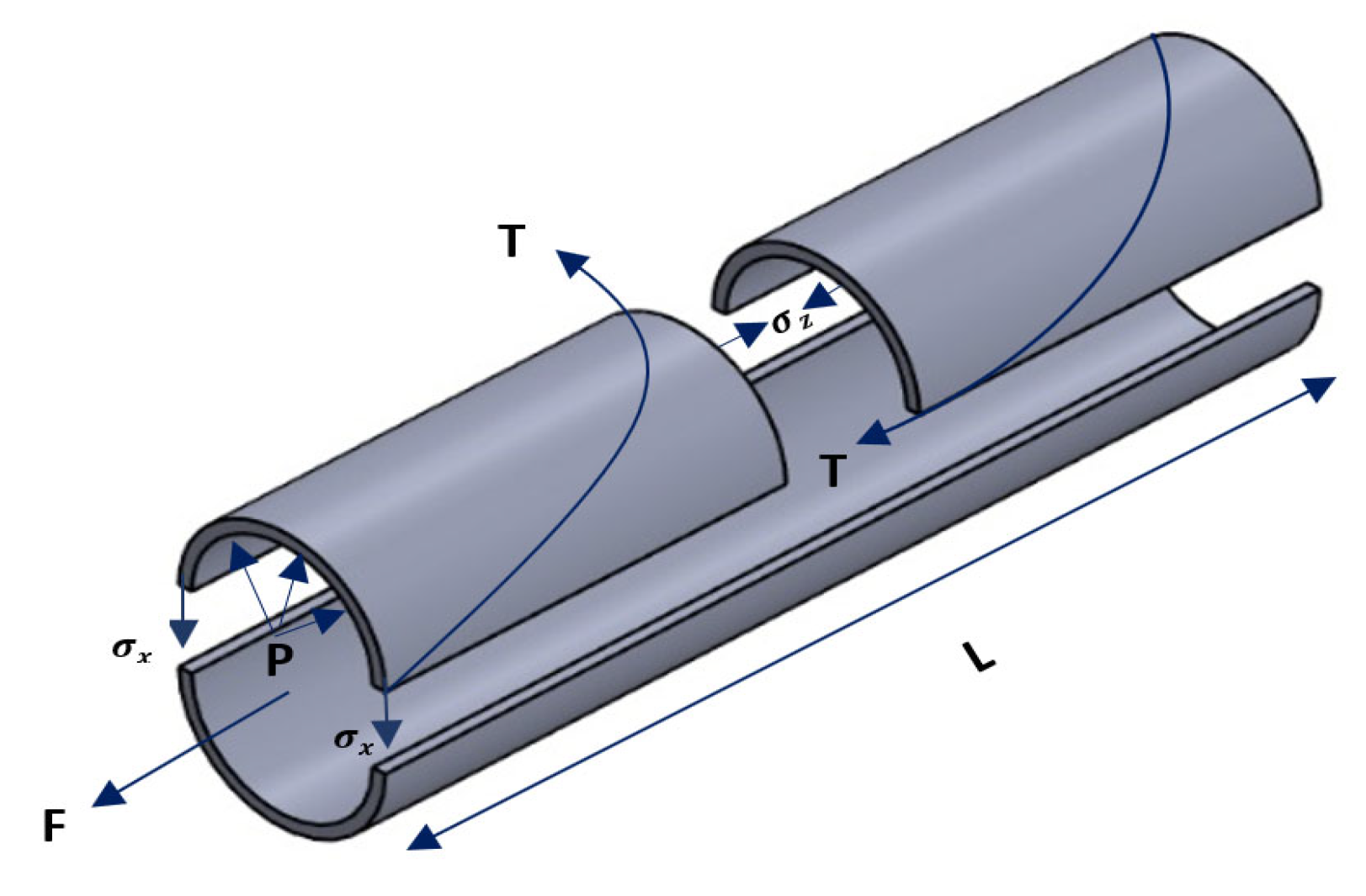
2.1. Mathematical Formulation for the Output Force

In this work, the force balance principle is employed to derive the preliminary force model [14,28], as proposed by Ferrasi et al. [45] and Kothera et al. [30]. Considering the free-body diagram of the PAM and the forces exerted on the actuator after providing an internal pressure as shown in Figure 3, the force equilibrium in the x and z directions yields:
x-direction:
P R t L = σ x t L + N T c o s ( α )
z-direction:
F + P ( R t ) 2 π = σ z A b l + T s i n ( α )
where σ is the stress in the bladder, T is the tension in the braid, F is the force generated by the actuator, and A b l is the cross-sectional area of the annular bladder. Assuming that the bladder has a constant volume ( V b l ), we can write:
V b l = π L R 0 2 R 0 t 0 2 = π L R 2 R t 2 = π L 2 R t t 2
The cross-sectional area of the bladder ( A b l ) is related to the bladder volume as:
A b l = V b l L
Substituting the tension (T) from Equation (4) into Equation (5) yields:
F = P R t 2 π + σ z A b l + P R t L σ x t L N tan α
Substituting tan α and A b l from Equations (3) and (7) into Equation (8) yields:
F = P L 2 2 π N 2 π R 2 + P V b l L t L 2 2 π N 2 R + σ z V b l L σ x t L 2 2 π N 2 R
Considering Equations (1) and (2), we can obtain the following relation:
2 π N R B 2 + L B 2 = 1
Finally, substituting R 2 from Equation (10) into (9) yields:
F = P 4 N 2 π 3 L 2 B 2 + P V b l L t L 2 2 π N 2 R + σ z V b l L σ x t L 2 2 π N 2 R
The first term in Equation (11) is the well-known Gaylord force model [52], in which the effect of nonlinearity and the thickness of the bladder are ignored. Other terms in Equation (11) are corrections that account for the effect of the thickness of the bladder on the produced force (second term) and the nonlinearities in the PAM when the length and radius of the bladder change after contraction or extension (last two terms).

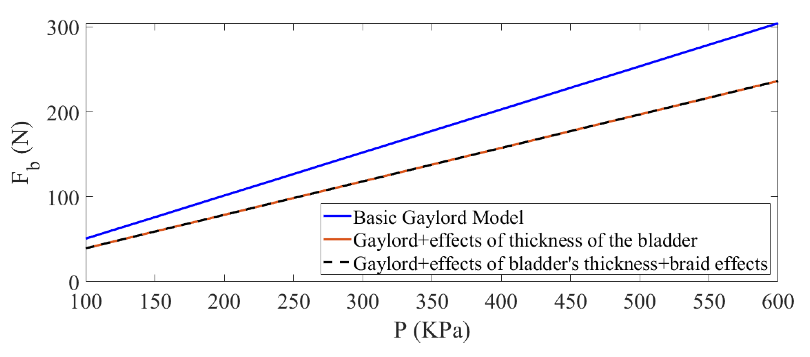
2.2. Refined Blocked Force Equation

To better capture the nonlinear response behavior of the PAM, additional force correction terms are required. However, the significance of each correction term depends on the application and even the size of the designed actuator. Because this study represents an attempt to maximize the blocked force, some of the correction terms would have insignificant effects on the final results. Based on the definition of the blocked force, no changes occur in the length and radius of the rubber tube, so no strain is generated in the bladder ( ε z = ε x = 0 ) . Therefore, the last two terms in Equation (11) regarding the nonlinearities of the bladder can be neglected. Furthermore, in the absence of any changes in the shape of the actuator, there would be no frictional or hysteretic losses. Although the dead-band pressure (pressure required to initiate the inflation of the rubber tube to contact surrounding braids) affects the calculations, this term can only be determined experimentally and depends on the material of the bladder. Therefore, the only correction term that may improve the predictions of the blocked force produced by the PAM is the elastic energy stored in the braid. Although the length is constant, small amounts of strain may exist in the braid (and in the rubber), contributing to lower blocked force measurements. To derive the force contribution due to the braid, the energy approach is used, focusing only on the Gaylord term. The force produced in the MPAM is simply represented by the derivative of the potential energy of the pressurized air with respect to the length of the actuator [53]. Since the potential energy of the air depends on its pressure and volume, the force of the actuator can be evaluated as:
F = d U d L = P d V d L
Assuming a cylindrical PAM with volume V = A L , we can write:
F = P A + P L d A d L
Assuming that no load is taken by the bladder, the first term in Equation (13) represents the force taken by the air; therefore, the remaining force (second term) should be carried by the braid. If the braid has n fibers, the load carried by each fiber can be represented as:
F b r = P L n sin ( α ) d A d L = P B n d A d L = 2 π P B n R d R d L
where A = π R 2 . Finally, the strain energy per unit volume in the braid can be formulated as:
W b r = 1 2 σ b r ε b r = 1 2 F b r A b r F b r E b r A b r = F b r 2 2 E b r A b r 2
where “ E b r ” is the Young’s modulus of the braid, and “ A b r ” is its cross-sectional area. The elastic force term associated with the braid can also be evaluated using Castigliano’s theorem and Equations (14) and (15) as:
F b r = V b r d W b r d L = V b r 2 F b r 2 E b r A b r 2 d F b r d L = 2 π 2 E b r A b r 2 P B n 2 R d R d L d R d L 2 + R d R 2 d L 2
Considering Equation (10), the radius ( R ) can be obtained as:
R 2 = B 2 L 2 2 π N 2
Obtaining first and second derivatives from both sides of Equation (17) yields:
R d R d L = L 2 π N 2   ;   d R d L 2 + R d R 2 d L 2 = 1 2 π N 2
Finally substituting relations in Equation (18) into Equation (16) and considering that V b r = B n A b r yields:
F b r = L E b r A b r n 4 π 2 P 2 B 3 ( 2 π N ) 4
Since the length of the bladder is constant in the blocked-force state, the effects of radial and axial strains on the bladder are ignored. Therefore, using only the first two terms in Equation (11) and considering the contribution of the force in the braid in Equation (19), the blocked force ( F b ) can be formulated as:
F b = P 4 N 2 π 3 L 2 B 2 + P V b l L t L 2 2 π N 2 R L E b r A b r n 4 π 2 P 2 B 3 ( 2 π N ) 4

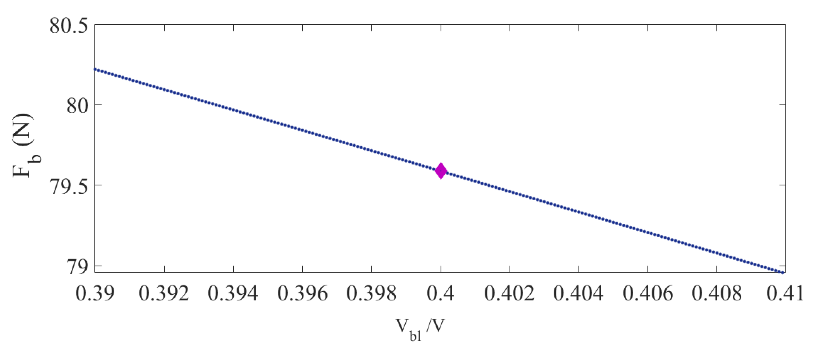
3. Optimization Formulation

An optimization methodology was formulated to determine the optimal geometrical parameters of a miniaturized McKibben muscle to maximize the blocked force under geometrical and volume constraints. In the present study, two optimization cases were investigated. In the first case, the blocked force includes the contribution of the braid force, as expressed in Equation (20), while in the second case, the effects of the braid force are neglected. The aim is to investigate the impacts of braid strand parameters on the final optimal blocked force.
The optimization problem discussed in the present study is a nonlinear optimization problem, which can be solved using various direct and indirect optimization methods. However, direct techniques are generally preferred due to their higher accuracies. A hybrid optimization method combining a stochastically based algorithm and a nonlinear programming technique was formulated in MATLAB®. Hybrid techniques are used to either choose one of the incorporated algorithms or, as in the case of this study, switch between them to combine the desired feature of each algorithm and end up with a more efficient overall algorithm that is superior to each individual algorithm. The hybrid optimization method used in this work combines the genetic algorithm (GA) and sequential quadratic programming (SQP). SQP is a rapid iterative method for solving constrained and unconstrained nonlinear problems that converge to the local optimum point by simultaneously enhancing the objective and tightening the feasibility of the constraints. This algorithm is suitable for real-world problems due to its capability to handle any degree of nonlinearity, including nonlinearity in the constraints. SQP is an efficient gradient-based nonlinear optimization algorithm that can accurately catch the local optimum solution near the starting point. The resulting optimum point greatly depends on the starting point, which is why an accurate initial point must be chosen. On the other hand, GA is a non-gradient optimizer that can stochastically converge to the near-global solution. It is a search-based method that emulates the process of natural selection and genetics in order to evolve the optimization problem toward the best solution. A population of prospective solutions is generated for a given problem, and their size is randomly determined and varied based on each problem. The fitness of each individual is assessed based on their ability to solve the problem, typically measured by the objective function value. This process continues until a stopping criterion is met, such as a maximum number of generations or a satisfactory level of fitness.
In this study, the optimization procedure was conducted in MATLAB® using the optimization toolbox, which provides various optimization algorithms to solve constrained and unconstrained nonlinear problems. First, MATLAB functions are defined for the mathematical formulation of the optimization problem, including the objective function of each case and the nonlinear constraints. The optimization procedure is initiated with the GA, and the results from this algorithm are fed into a local optimizer (SQP) as the starting point to obtain the “true” global optimal values.

3.1. Optimization Formulation: Case I

In this case, the effect of braid force is considered, and Equation (20) is used to evaluate the blocked force. Thus, the geometric parameters that significantly affect the performance of the MPAM are the radius and thickness of the bladder (R and t), the braid angle ( α ), the radius of the braid strands ( R b r ) , and the number of braid fibers used to make the braided sleeving ( n ). The blocked force equation (Equation (20)) can be explicitly described with respect to the design variables. For this purpose, Equation (1) is substituted into Equation (2) to obtain:
N = L cot ( α ) π D = L cot ( α ) 2 π R
Moreover, assuming a cylindrical shape for the MPAM, the volume of the bladder and the cross-sectional area of the braid strands can be obtained as:
V b l = π R 2 L   ;   A b r = π R b r 2
Finally, substituting Equations (21) and (22) into Equation (20) and considering Equation (1) for B yields:
F b = P π R 2 cot 2 ( α ) 3 ( 1 sin ( α ) ) 2 + P π R 2 2 π R t cot 2 ( α ) s i n ( α ) E b r R b r 2 n 4 π P 2 R 4 cos 4 ( α )
Equation (23) can be further simplified as:
F b = P π R 2 2 tan 2 α 1 + 2 R t t 2 2 t R ( tan 2 α ) 4 P R 4 sin ( α ) E b r n R b r 2 ( cos ( α ) ) 4
The blocked force given in Equation (24) explicitly depends on the design variables R , t , α , R b r ,   and   n . The braid is chosen among commonly used PET (polyethylene terephthalate) braids with a specific modulus of elasticity ( E b r = 2.1   MPa ), and the pressure of the air inside the bladder is considered to be constant in each optimization procedure.
The identified design variables are subjected to geometrical constraints (side constraints) and a nonlinear constraint related to the ratio of the thickness of the bladder to its radius. In order to ensure constant pressure throughout the length of the actuator, the ratio between the volume of the bladder and the volume of the entire structure of the actuator (internal volume of the actuator) should fall within a specific range. Assuming that the radius of the actuator is equal to the outer radius of the bladder, the aforementioned volume ratio can be calculated as:
V b l V = π L R 2 R t 2 π L R 2 = π L 2 R t t 2 π L R 2 = t R ( 2 t R )
As Equation (25) reveals, the ratio between the volume of the bladder and the volume of the actuator is directly proportional to the ratio between the wall thickness of the bladder and its outer radius. This ratio is usually higher for miniaturized PAMs, since the bladder constitutes a much larger portion of the actuator’s cross-sectional area. The recommended range for this ratio is between 0.4 and 2 for MPAMs [29].
The side constraints are the limits considered for the dimensions of the required MPAM. These limits are chosen based on the applications for which the MPAM is being designed and the typical dimensions of previously designed and commercialized MPAMs. Based on the descriptions of the optimization problem, it may be formally formulated as:
Find the vector of design variables : X = R , t , α , R b r , n T To maximize :   F b ( X )   in Equation (24) Subject to the following constraints : X m i n X X m a x V b l V 2 0 0.4 V b l V 0
The lower and upper bounds of each design variable are provided in Table 1.

3.2. Optimization Formulation: Case II

In this case, the effect of braid force is neglected in Equation (20); therefore, the blocked-force equation is simplified as:
F b ´ = P π R 2 2 t a n 2 α 1 + 2 R t t 2 2 t R ( t a n 2 α )
Comparison of Equation (27) with Case I shows that that due to the absence of the term related to the braid force, the design variables are considered to be R , t ,   a n d   α . The constraints are similar to those in Case I stated in Equation (26). The optimization problem can therefore be formulated as:
Find the vector of design variables : X = R , t , α T To maximize :   F b ´ ( X ) Subject to the following constraints : X m i n X X m a x V b l V 2 0 0.4 V b l V 0

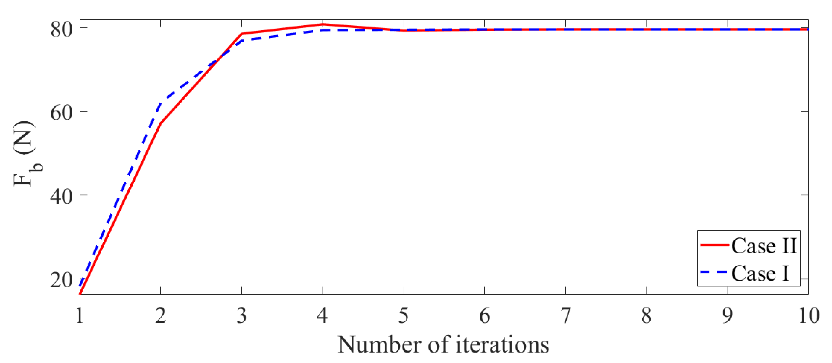
4. Optimization Results

In the first step, to determine the contributing effects of the braid geometry on the maximized blocked force and the optimal dimensions of an MPAM, a comparison is made between Cases I and II described in Section 3.1 and Section 3.2, respectively. The optimum design variables and the blocked force obtained for each case are presented in Table 2. For the sake of clarity, the results are only presented for an inlet pressure of 200 kPa; however, similar results were obtained for other operating pressures. As demonstrated in Table 2, the braid strand parameters do not influence the optimum values of the design variables common in both optimization formulations ( R , t , α ). The results demonstrate that the contribution of the braid force has a very slight effect on the maximized blocked force. Hence, optimizing the braid strand parameters included in the term that represents the braid force ( R b r , n ) does not have any effect on optimizing the design of an MPAM to maximize the generated blocked force and can therefore be neglected. This would also lead to a simpler and more cost-effective MPAM that can be fabricated using braids available on the market instead of a customized braided sleeving. Figure 4 illustrates the iteration history for both optimization cases. The iteration number represents the number of times the optimization algorithm was run before converging to the optimum values. As mentioned previously, Case I comprises five design variables, while Case II comprises three design variables. However, the initial values for the design variables that were common in both cases were equal to make the initial conditions of the optimization algorithm similar for both cases. The value of the objective function for both cases converges to the same optimum blocked force, confirming that both cases lead to the same optimized dimensions for the MPAM.
The inlet pressure does not have any effect on the optimal design parameters regardless of the blocked force formulations for Case I (Equation (24)) and Case II (Equation (27)), as shown in Table 3. By increasing the inlet pressure from 50 kPa to 600 kPa, the generated optimal blocked force increases from almost 20 N to 239 N.
Figure 5 shows the variation of the optimal blocked force with respect to inlet pressure using different models, including the basic Gaylord model, the Gaylord model incorporating the effects of the thickness of the bladder, and the Gaylord model including the effects of the bladder’s thickness and energy stored in the braid. The magnitude of the blocked force anticipated by the simple Gaylord model is clearly higher than the calculated amounts of blocked force using the other two models, particularly at higher pressures. This is due to the fact that the thickness of the bladder, which plays a major role in the generated force by an MPAM, is not considered in the Gaylord force model. On the other hand, there are no significant differences between the anticipated amounts of force using the other two models, confirming that the correction term due to the effects of the braided sleeving does not make a noticeable difference in the level of accuracy of the force prediction. Thus, the Gaylord model incorporating the effects of the thickness of the bladder can be effectively used to accurately predict the blocked force in MPAMs.
Table 4 provides the optimal results using the GA alone and combined GA and SQP, in which final optimum results from the GA were used as the initial point for the SQP algorithm. The GA algorithm converges to a near-global point after only three iterations. The findings reported for the GA are the average of the results obtained after repeating the procedure 10 times, since this algorithm gets trapped at a different near-global point in each run. The optimum values from the GA are then used as the initial points in the SQP algorithm, which converges to the true global optimum points after five more iterations.
Further examination of the optimal design parameters reveals that the radius of the bladder and the braid angle are converged to their upper bounds, which is justifiable based on the existing relationship between each dimensional parameter of an MPAM and its force output [29,30,54,55]. Moreover, the nonlinear constraint on the volume ratio is active on its lower bound. To investigate the effect of the lower bound of the volume ratio on the optimal blocked force, a post-optimality analysis was conducted in which the optimal solution was evaluated by varying the lower bound of the volume ratio (q) by ±2% around its original value of 0.4, while other constraints were kept the same. The new optimum points and the cost function are reported in Figure 6 and Table 5. As indicated in Table 5, there is no change in the optimal values of the bladder radius and the braid angle, while the bladder thickness increases by increasing q. Figure 6 illustrates that the optimal blocked force also reduces linearly with an increase in q, which is attributed to the increase in the optimum thickness of the bladder. Results suggest that reducing q by 2% yields an increase in the blocked force by almost 1.5%. In the present study, based on the dimensional constraints that exist in the design of MPAMs for small-scaled robotic systems, q is limited to 0.4.

5. Experimental Verification

The optimally designed MPAM was fabricated and experimentally tested under varying inlet pressures. In the following sections, the fabrication method, test setup, and test procedure are discussed.

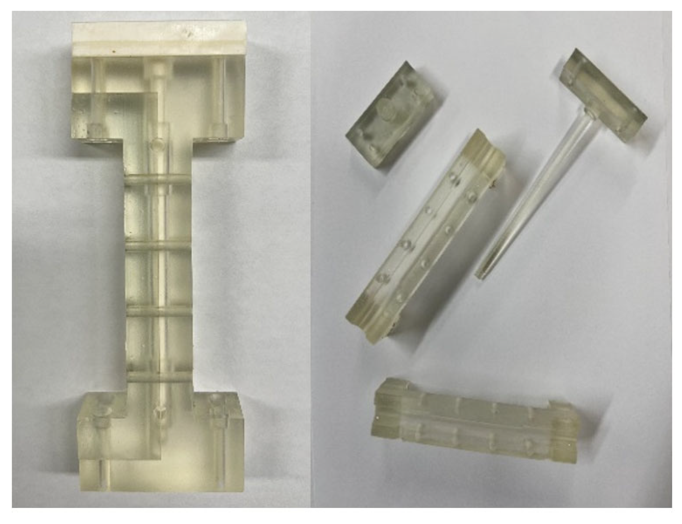
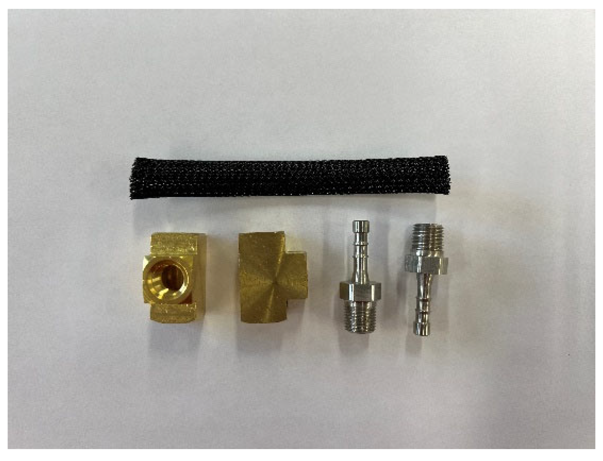
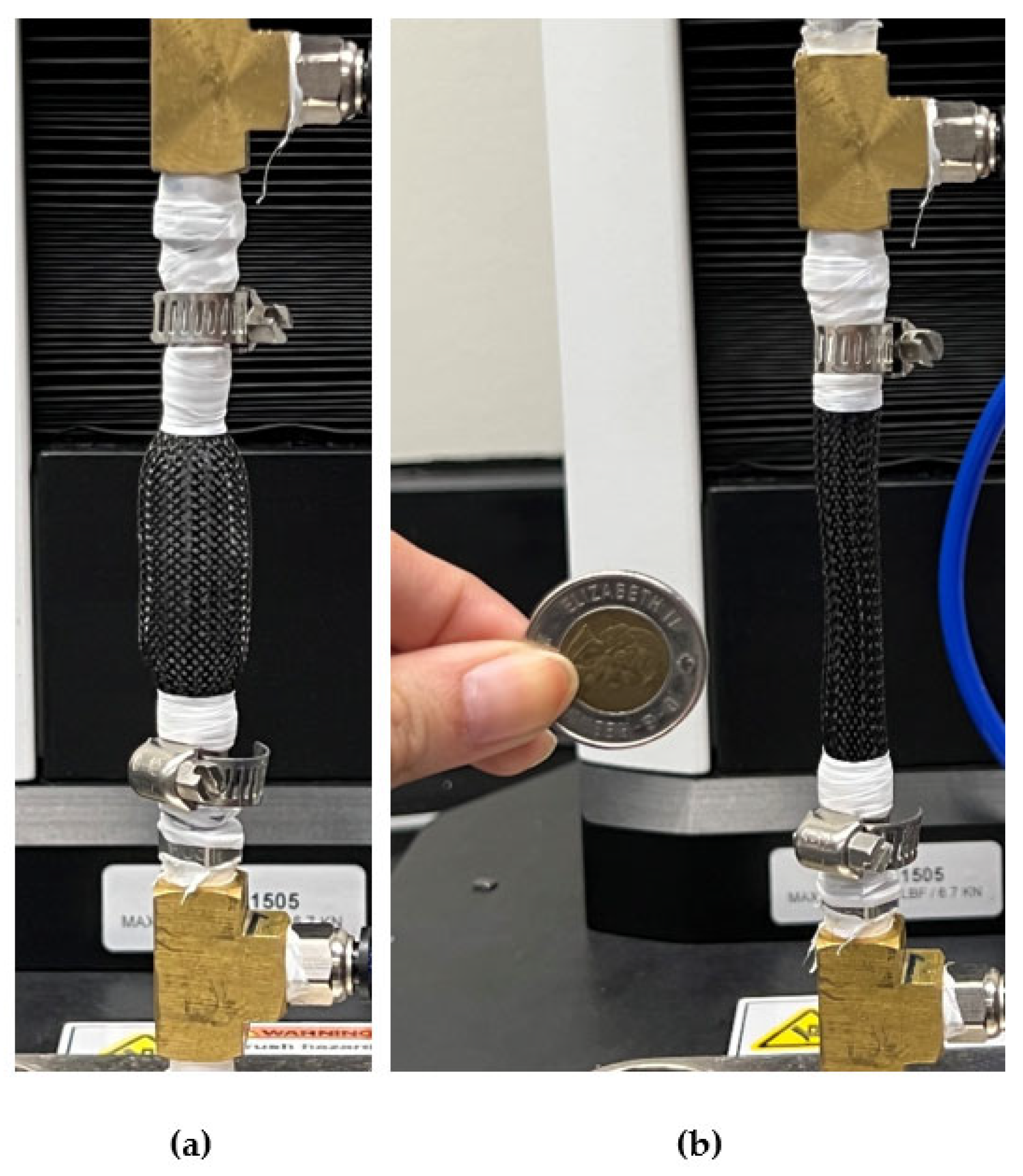
5.1. Fabrication of the Optimized MPAM

The MPAM is composed of three major components: (1) a cylindrical bladder to contain the pressurized air that powers the muscle; (2) a braided sleeve to convert the radial expansion of the muscle into axial contraction, creating force; and (3) two end fittings, one of which seals the muscle cylinder and the other of which serves as an air intake channel.
In this study, the MPAM was fabricated using low-cost materials that are commercially available. Before assembling the actuator, a customized bladder must be fabricated with the required optimal dimensions because such dimensions cannot be found in any of the silicone tubes available on the market. To that end, a 3D-printed mold (illustrated in Figure 7) was fabricated using a FormLabs Form 3+ printer with an accuracy of 25 μ and clear B4 resin. Each of the two outer halves contains a semicircular groove with an inner diameter of 3 mm to form a bladder with the required outer diameter (6 mm). Due to the limited accuracy of the equipment used for the experiment, the optimal thickness of the bladder is set to 0.7 mm; therefore, the diameter of the inner cylinder that matches the inner diameter of the bladder is set to 4.6 mm to yield a tube with the required thickness of 0.7 mm. The components of the mold are screwed to each other using the embedded holes on each part. Since the length of the bladder does not affect the blocked force, it is set to 50 mm for the sake of miniaturization. However, the mold is designed with a length of approximately 60 mm, which is equal to the active length of the MPAM, plus a further 10 mm to account for the parts that overlap the end fittings. After fabrication of the mold, the material of the bladder is prepared by mixing parts A and B (1:1) of Ecoflex-50 silicone (Smooth-On, Inc., Macungie, PA, USA) for 40 s inside a vacuum mixer (Thinky (Laguna Hills, CA, USA), ARV-200) with a speed of 2000 rpm and under a pressure of 27 inHg to eliminate all the air bubbles. The silicone mixture is then injected into the mold (the cavity between the outer and inner cylinder) and cured for 24 h at room temperature to form a cylindrical tube for the bladder. A braided sleeving with a nominal diameter of 6.35 mm and a braid angle of 72 degrees was chosen after procuring a variety of PET (polyethylene terephthalate) braids from the supplier and measuring their respective braid angles (TechFlex®–Clean Cut (CCP0.25BK)). The braided sleeving is then cut to the same length as the silicone tube to completely cover the bladder. The end of the braided sleeving is burned to prevent fraying. Finally, two end fittings are tightly placed inside the inner diameter of the bladder to seal the ends of the MPAM. The various components of the MPAM and its assembled configuration are illustrated in Figure 8 and Figure 9, respectively.

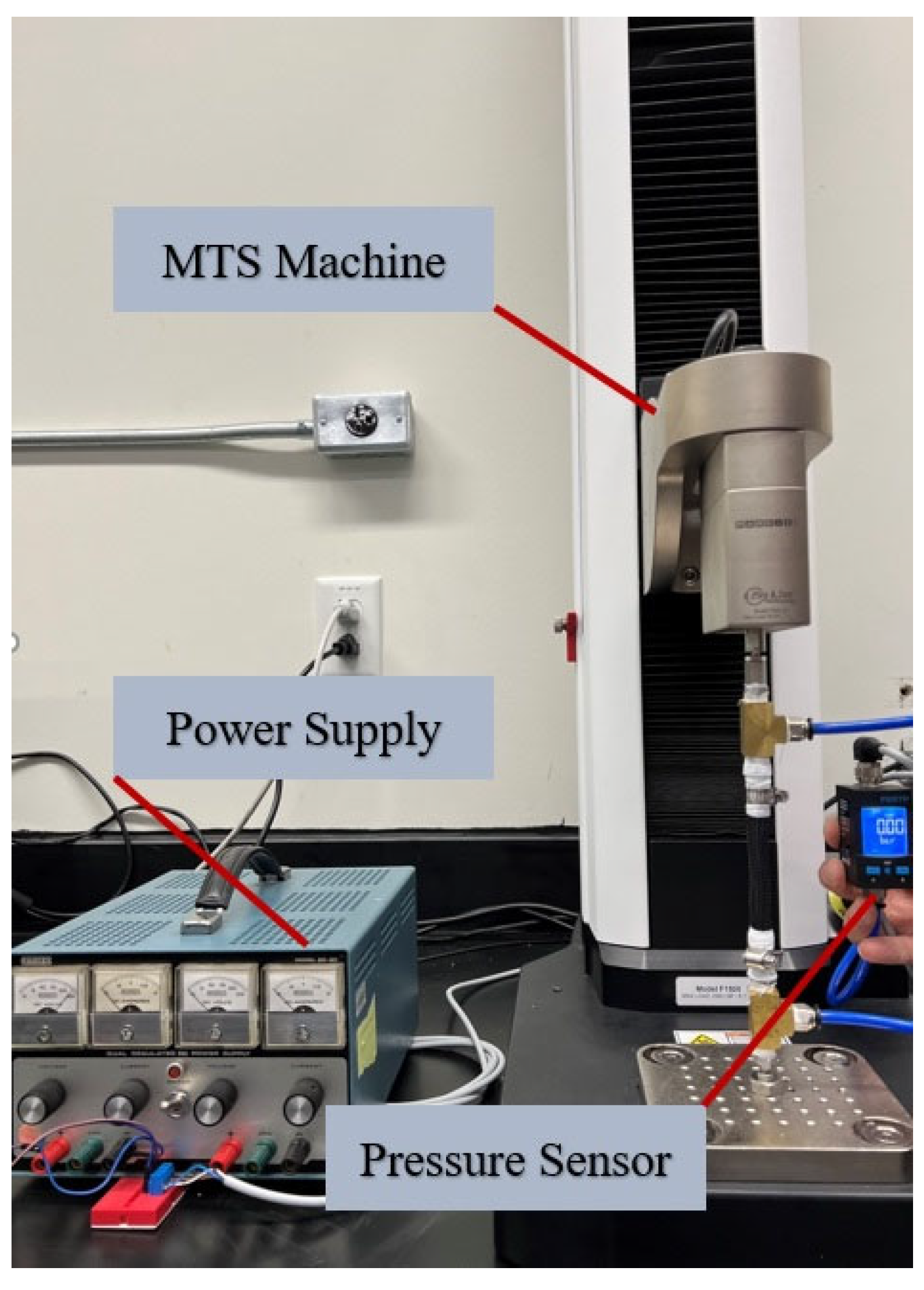
5.2. Test Setup and Procedure

A test setup was designed to evaluate the performance of the MPAM under varying pressures and validate the optimization results. Quasi-static tests were conducted using an MTS machine (F1505; max load, 6.7 kN), which is capable of measuring both force and displacement (sensor mark-10; model FS05-50; max load, 250 N). The pressure supplied to the actuator was monitored using a pressure sensor (Festo® (Esslingen, Germany), SPAU-P10R-H-G18FD-L-PNLK-PNVBA-M12U). Figure 10 shows the MPAM installed within the test setup.
Since the primary purpose of the tests is to measure the blocked force under various constant pressures, both MTS grippers were fixed throughout the experiment to maintain the MPAM in its initial state. In the first step, the inlet pressure was increased gradually from 0 kPa to the state where the MPAM begins producing force. The amount of pressure in this state is referred to as the dead-band pressure, which is attributed to the nonlinearity of the bladder material that results in a discontinuity in the relationship between the pressure and the diameter, resulting in a sudden inflation above a specific pressure [53]. Then, in order to obtain the blocked force as a function of pressure, tests were conducted at different pressures ranging from 20 kPa to 300 kPa with increments of 20 kPa. In each case, the pressure was kept constant, and the readings from the force sensor were recorded as the amounts of the blocked force. To assess the repeatability and reliability of the measurements, each test was repeated three times, and the average of the recorded data was used to determine the relationship between the air pressure and the blocked force.
Once the amounts of blocked force were recorded for each specific pressure, one of the MTS grips was unlocked to allow the MPAM to contract freely up to its state of maximum contraction, where the actuator would no longer produce force. At this point, the variation in the initial length of the actuator was recorded as the amount of the free contraction for the MPAM. In order to derive the correlation between the free contraction and the inlet pressure, the free contraction of the MPAM was recorded under various pressures from 50 kPa to 250 kPa with increments of 50 kPa.

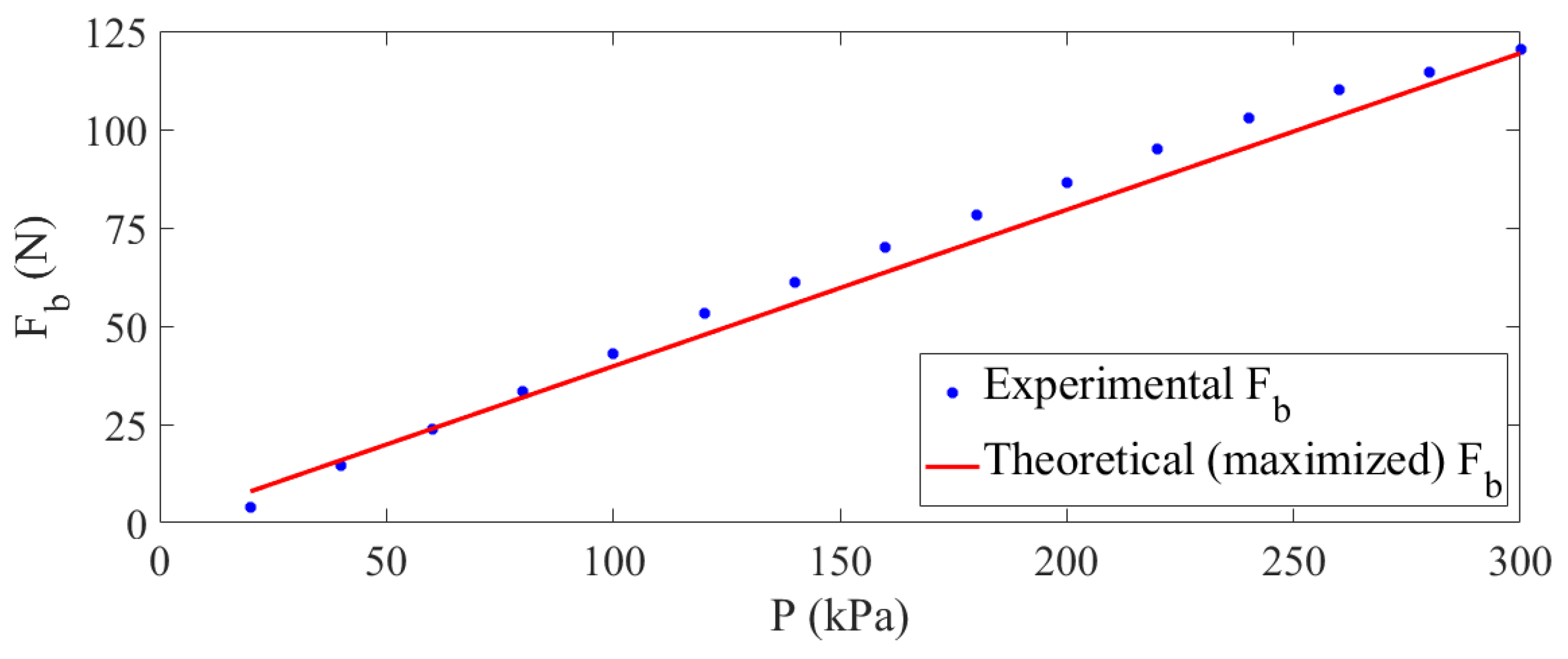
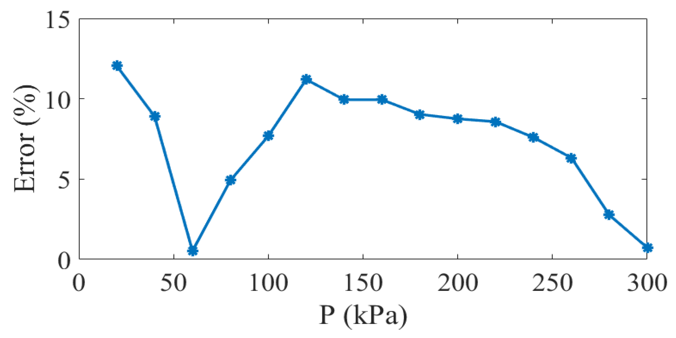
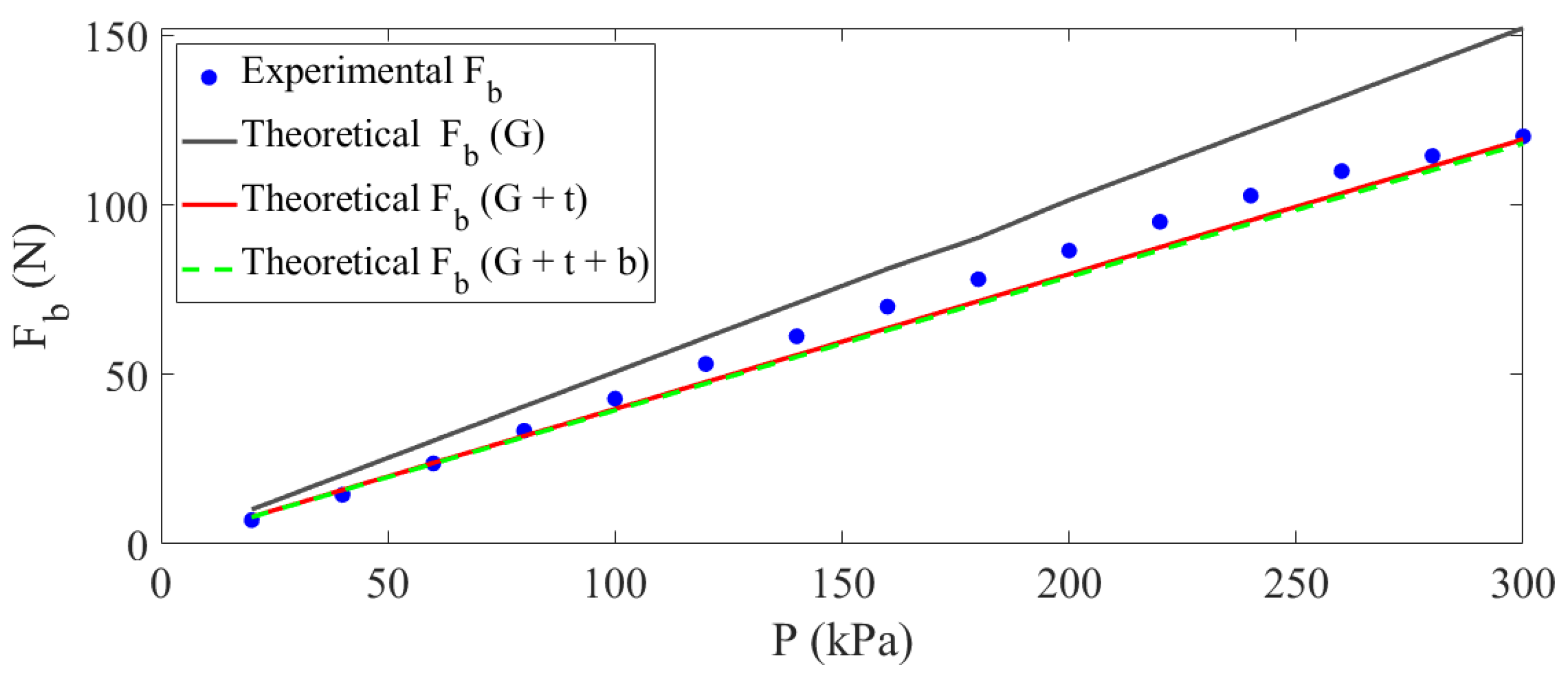
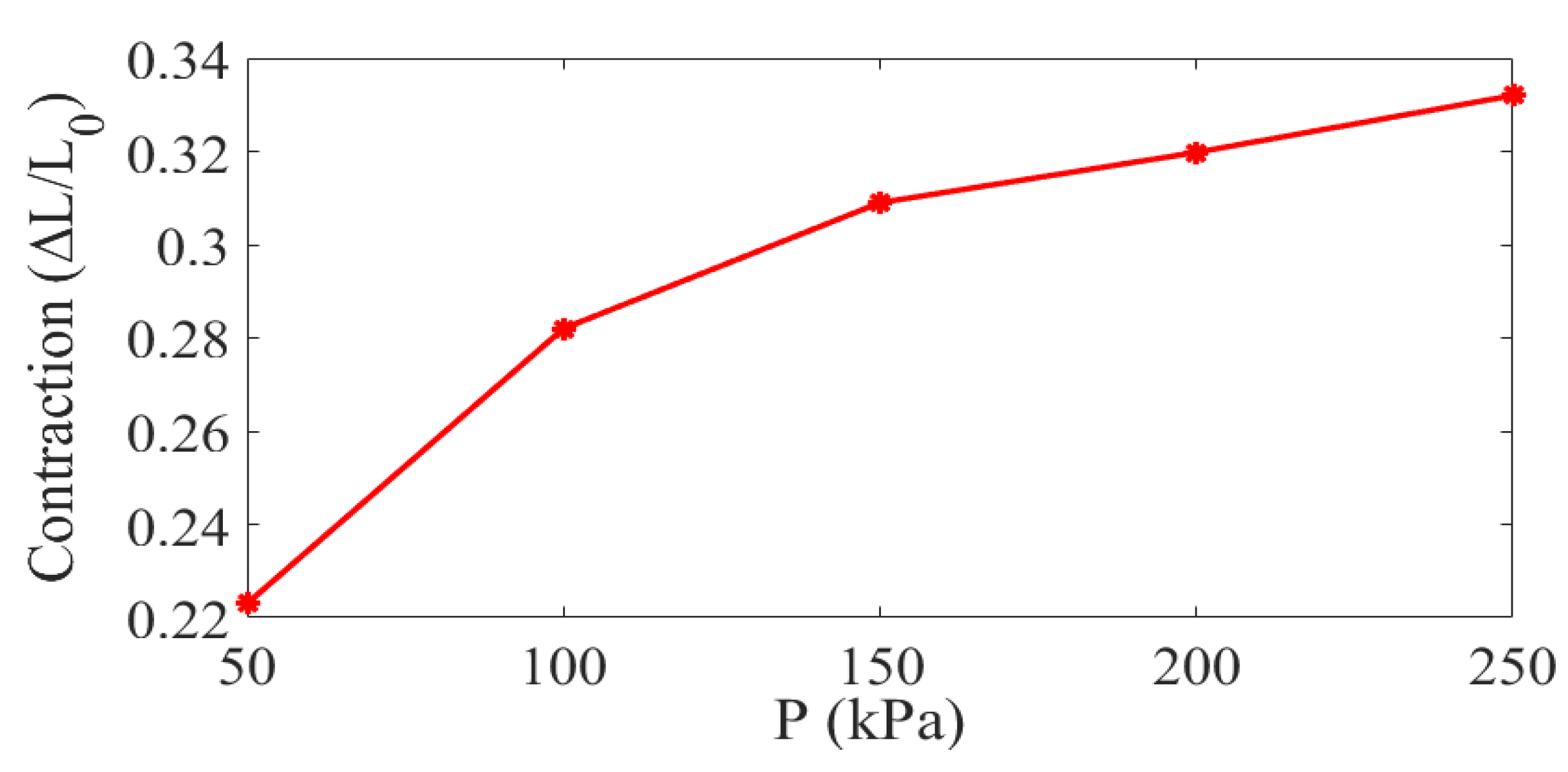
5.3. Experimental Results

The results of the quasi-static tests are shown in Figure 11, displaying the variation of the blocked force produced by the MPAM with internal pressure. As observed in Figure 11, the MPAM initiates generating force when the inlet pressure reaches 20 kPa, which is the dead-band pressure for the designed MPAM. The dead-band pressure depends on the material of the bladder, as well as its thickness and diameter. Pillsbury et al. [13] showed that PAMs with higher volume ratios ( V b l V ) require higher pressures (meaning a higher P D B ) to produce the same amount of force as PAMs with lower volume ratios. Since the ratio of the volume of the bladder to the volume of the PAM is proportional to the ratio between the radius and thickness of the bladder, it can be concluded that a greater thickness can also result in an increase in the dead-band pressure. This can be explained by the fact that a higher force is needed to overcome the elasticity of a thick bladder during its deformation. The fabricated optimized MPAM has an extremely small thickness-to-radius ratio; consequently, it has a significantly low dead-band pressure and begins producing a higher level of force when the bladder is pressurized to lower pressures, thereby reducing the required energy input.
The results show that the blocked force increases nearly linearly with pressure, which is consistent with the findings of earlier studies [13,14,32]. Due to the imperfections in the tubular silicone and the limitations of the MTS machine, the maximum pressure was limited to 300 kPa, yielding a maximum blocked force of 120 N. A comparison between the experimental and theoretical results is also provided in Figure 11. A very good agreement exists between the optimized blocked force obtained using Equation (27) and the experimental results. The error between simulation and experimental results for the blocked force under various pressures is generally less than 10%, as shown in Figure 12. Since the dead-band pressure is neglected in the theoretical force equation, the highest error between the simulation and experimental results is found to be at the inlet pressure of 20 kPa (dead-band pressure for the designed MPAM), under which the MPAM starts generating blocked force. The minor discrepancies between the experimental and theoretical results can be attributed to the limitations of the fabrication and testing procedures, as well as the assumptions made during the derivation of the optimization formulation.
To complement the conclusion drawn from Figure 5, the optimized parameters were employed as inputs in three distinct froce models (G: simple Gaylord; G + t: Gaylord including the effects of the thickness of the bladder; and G + t + b: Gaylord incluidng the effects of the thickness of the bladder and the energy stored in the braided sleeving). Figure 13 compares the theoretical values of the blocked force obtained using the aforementioned force models with the experimental data. The results indicate that, in agreement with existing literature, the Gaylord model overestimates the blocked force in comparison to the other two eqations. Additionally, the results support the conclusions drawn from Figure 5 concerning the insignificant discreprency between force estimations using the second and third force equations.
In addition to the blocked force, the free contraction is also an important parameter based on which the performance of an MPAM is evaluated. To evaluate the variation of the free contraction with respect to an increase in the inlet pressure, a dimensionless parameter is defined as:
C o n t r a c t i o n   r a t i o = L L 0
where L 0 is the initial active length of the actuator, and L is the amount by which the MPAM contracts. Results for the contraction ratio under various inlet pressures are shown in Figure 14. The contraction ratio increases nonlinearly with pressure, in agreement with the trends reported in earlier studies [30,55]. It is interesting to note that as the pressure rises, the contraction ratio increases at a slower rate, indicating that the free contraction of the MPAM reaches a saturation at high inlet pressures. When the pressure increases from 50 kPa to 100 kPa, there is a sharp rise in the contraction ratio; however, the contraction ratio increases at a considerably slower rate between 100 kPa and 250 kPa. This behavior can be explained by the fact that the diameter of the bladder cannot expand beyond a certain value.
Table 6 compares the specifications and outputs of the proposed MPAM in the present study with those of previously designed MPAMs. As evidenced by the provided data, the proposed MPAM with optimized dimensions is capable of producing significantly higher amounts of blocked force (in some cases, twice as much) in comparison to the other PAMs with similar dimensions. For instance, the blocked force generated by the developed MPAM is approximately 14.2% greater than the force output of the commercialized MPAM from Festo® with the same bladder diameter. It is noteworthy that the developed MPAM is capable of theoretically producing nearly 238 N at 600 kPa of inlet pressure, which is considerably higher than the maximum amount of blocked force that has ever been generated by existing MPAMs. These findings provide convincing evidence that the optimization procedure was successful in maximizing the blocked force produced by an MPAM. It is interesting to note that while maximizing the free contraction was not the objective of the optimization analysis, the developed MPAM yields higher free contractions compared to most of previously designed MPAMs. The free contraction of the actuator optimized in this work is almost 23% higher than that of the MPAM from Festo®, indicating that, in addition to higher force outputs, the proposed MPAM, which was fabricated using cost-effective material available on the market, is capable of producing large amounts of displacement while being compact enough to fit within the majority of miniaturized robotic applications.

6. Conclusions

The primary goal of the current study was to formulate a novel design optimization strategy to determine the optimal dimensional parameters of an MPAM as a small-sized actuator with maximized force output. A force model with acceptable accuracy was derived for the MPAM based on the force balance equations. This force model, which includes two correction terms regarding the effects of the thickness of the bladder and the energy stored in the braid, was used as the objective function in the optimization problem. To study the effects of the braid force on the optimum parameters and the accuracy of the force prediction, two optimization formulations were derived using two different objective functions: one including the braid correction term and the other neglecting it. Comparing the results of these two optimization problems revealed that considering the braid force does not influence the optimized dimensions of the actuator or the maximized amount of blocked force. Therefore, neglecting this term results in a simpler design of the MPAM, which can be fabricated using a braided sleeve available on the market rather than a customized one. To validate the optimization results, an experimental setup was designed using an MPAM fabricated with a customized bladder with optimized dimensions. The results of the quasi-static tests revealed considerable agreement between the anticipated amount of blocked force and the measured values, exhibiting an overall error of less than 10%. A comparison between the performance of the optimized MPAM and previous miniaturized PAMs indicated that the actuator designed in this work is capable of producing higher amounts of force (at least 14%) and even free contraction while requiring less input work and lower inlet pressures. According to the experimental results, the proposed MPAM with optimum dimensions is capable of producing around 120 N while being pressurized to 300 kPa, indicating an enhancement of 14.2% compared to the blocked force generated by commercialized MPAMs from Festo®, in addition to presenting an approximately 23% higher degree of free contraction. The proposed MPAM is proven to be of practical importance in miniaturized systems that require a compact, lightweight, and cost-effective, actuator capable of producing large amounts of force and even displacement. Overall, the proposed design optimization strategy for MPAMs with the derived force model and the comparison of optimization formulations with and without braid correction term can provide valuable insights for the design of MPAMs for various applications. While prior attempts to maximize the force and contraction outputs of PAMs have resulted in bulky designs, the higher force output and free contraction feature of the proposed MPAM can lead to significant improvements in the performance of miniaturized systems.

Author Contributions

Conceptualization, S.Z. and R.S.; methodology, S.Z. and R.S.; software, S.Z.; validation, S.Z. and S.A.M.; formal analysis, S.Z.; investigation, S.Z.; experimentation, S.Z. and S.A.M.; resources, S.Z. and S.A.M.; data curation, S.Z. and S.A.M.; writing—original draft preparation, S.Z.; writing—review and editing, S.Z. and R.S.; visualization, S.Z. and S.A.M.; supervision, R.S.; project administration, R.S.; funding acquisition, R.S. All authors have read and agreed to the published version of the manuscript.

Funding

This research was funded the Natural Sciences and Engineering Research Council of Canada (NSERC) (grant number no. RGPIN and DG-DND-2021-03482).

Institutional Review Board Statement

Not applicable.

Informed Consent Statement

Not applicable.

Data Availability Statement

The data supporting the findings of this study are available upon request.

Conflicts of Interest

The authors declare no conflict of interest.

References

  1. Schröder, J.; Erol, D.; Kawamura, K.; Dillman, R. Dynamic pneumatic actuator model for a model-based torque controller. In Proceedings of the IEEE International Symposium on Computational Intelligence in Robotics and Automation, CIRA, Kobe, Japan, 16–20 July 2003; Volume 1, pp. 342–347. [Google Scholar] [CrossRef]
  2. Schröder, J.; Kawamura, K.; Gockel, T.; Dillmann, R. Improved Control of a Humanoid Arm Driven by Pneumatic Actuators. In Proceedings of Humanoids. 2003. Available online: https://www.techfak.uni-bielefeld.de/~rhaschke/lehre/WS04/humanoids/papers/McKibben.pdf(accessed on 21 May 2023).
  3. Wang, Y.; Xu, Q. Design and testing of a soft parallel robot based on pneumatic artificial muscles for wrist rehabilitation. Sci. Rep. 2021, 11, 1273. [Google Scholar] [CrossRef] [PubMed]
  4. Zhong, J.U.N.; Zhao, D.; He, C.; Zhu, Y.U.E.; Zhang, Q. A Rehabilitation Robot Driven by Pneumatic Artificial Muscles. J. Mech. Med. Biol. 2020, 20, 20400084. [Google Scholar] [CrossRef]
  5. Magnetti Gisolo, S.; Muscolo, G.G.; Paterna, M.; De Benedictis, C.; Ferraresi, C. Feasibility study of a passive pneumatic exoskeleton for upper limbs based on a mckibben artificial muscle. In Mechanisms and Machine Science; Springer Science and Business Media B.V.: Berlin/Heidelberg, Germany, 2021; pp. 208–217. [Google Scholar] [CrossRef]
  6. Kalita, B.; Dwivedy, S.K. Nonlinear dynamic response of pneumatic artificial muscle: A theoretical and experimental study. Int. J. Non-Linear Mech. 2020, 125, 103544. [Google Scholar] [CrossRef]
  7. Choi, H.S.; Lee, C.H.; Baek, Y.S. Design and Validation of a Two-Degree-of-Freedom Powered Ankle-Foot Orthosis with Two Pneumatic Artificial Muscles. Mechatronics 2020, 72, 102469. [Google Scholar] [CrossRef]
  8. Lee, Y.K.; Shimoyama, I. A skeletal framework artificial hand actuated by pneumatic artificial muscles. In Proceedings of the 1999 IEEE International Conference on Robotics and Automation (Cat. No.99CH36288C), Detroit, MI, USA, 10–15 May 1999; Volume 2, pp. 926–931. [Google Scholar] [CrossRef]
  9. Robinson, R.M.; Kothera, C.S.; Woods, B.K.S.; Vocke, R.D.; Wereley, N.M. High specific power actuators for robotic manipulators. J. Intell. Mater. Syst. Struct. 2011, 22, 1501–1511. [Google Scholar] [CrossRef]
  10. Tondu, B.; Ippolito, S.; Guiochet, J.; Daidie, A. A Seven-degrees-of-freedom robot-arm driven by pneumatic artificial muscles for humanoid robots. Int. J. Robot. Res. 2005, 24, 257–274. [Google Scholar] [CrossRef]
  11. Kalita, B.; Leonessa, A.; Dwivedy, S.K. A Review on the Development of Pneumatic Artificial Muscle Actuators: Force Model and Application. Actuators 2022, 11, 288. [Google Scholar] [CrossRef]
  12. McKibben, J.L. Artificial Muscle. 1957. Available online: https://cyberneticzoo.com/ (accessed on 22 December 2022).
  13. Takagi, T.; Sakaguchi, Y. Rubbertuator, Bridgestone Company. 1983. Available online: https://cyberneticzoo.com/ (accessed on 7 February 2022).
  14. Mižáková, J.; Pitel, J.; Tóthová, M. Pneumatic artificial muscle as actuator in mechatronic system. Appl. Mech. Mater. 2013, 460, 81–90. [Google Scholar] [CrossRef]
  15. Park, Y.L.; Wood, R.J. Smart pneumatic artificial muscle actuator with embedded microfluidic sensing. In Proceedings of the IEEE Sensors, Baltimore, MD, USA, 3–6 November 2013. [Google Scholar] [CrossRef]
  16. Wakimoto, S.; Misumi, J.; Suzumori, K. New concept and fundamental experiments of a smart pneumatic artificial muscle with a conductive fiber. Sens. Actuators A Phys. 2016, 250, 48–54. [Google Scholar] [CrossRef]
  17. Kanno, R.; Watanabe, S.; Shimizu, K.; Shintake, J. Self-Sensing McKibben Artificial Muscles Embedded with Dielectric Elastomer Sensor. IEEE Robot. Autom. Lett. 2021, 6, 6274–6280. [Google Scholar] [CrossRef]
  18. Fu, C.; Wang, K.; Tang, W.; Nilghaz, A.; Hurren, C.; Wang, X.; Xu, W.; Su, B.; Xia, Z. Multi-sensorized pneumatic artificial muscle yarns. Chem. Eng. J. 2022, 446, 137241. [Google Scholar] [CrossRef]
  19. do Rosario Carvalho, A.D.; Karanth, P.N.; Desai, V. Design and characterization of a pneumatic muscle actuator with novel end-fittings for medical assistive applications. Sens. Actuators A Phys. 2021, 331, 112877. [Google Scholar] [CrossRef]
  20. Tjahyono, A.P.; Aw, K.C.; Devaraj, H.; Surendra, W.; Haemmerle, E.; Travas-Sejdic, J. A five-fingered hand exoskeleton driven by pneumatic artificial muscles with novel polypyrrole sensors. Ind. Robot. Int. J. Robot. Res. Appl. 2013, 40, 251–260. [Google Scholar] [CrossRef]
  21. Chakravarthy, S.; Aditya, K.; Ghosal, A. Experimental characterization and control of miniaturized pneumatic artificial muscle. J. Med. Devices 2014, 8, 041011. [Google Scholar] [CrossRef]
  22. Lathrop, B.; Ourak, M.; Poorten, E.V. Miniature Pneumatic Artificial Muscles for Use in Surgical Devices, ACTUATOR. In Proceedings of the International Conference and Exhibition on New Actuator Systems and Applications, Mannheim, Germany, 29–30 June 2022. [Google Scholar]
  23. Markus, A.T.; Sobczyk, M.R.; Perondi, E.A. Modeling, Control, and Simulation of a 3-Degree of Freedom Mechanism Actuated by Pneumatic Artificial Muscles for Upper Limb Prosthesis Application. J. Mech. Robot. 2023, 15, 011002. [Google Scholar] [CrossRef]
  24. Ashwin, K.P.; Ghosal, A. Static Modeling of Miniaturized Pneumatic Artificial Muscles, Kinematic Analysis, and Experiments on an Endoscopic End-Effector. IEEE/ASME Trans. Mechatron. 2019, 24, 1429–1439. [Google Scholar] [CrossRef]
  25. Tadano, K.; Akai, M.; Kadota, K.; Kawashima, K. Development of grip amplified glove using bi-articular mechanism with pneumatic artificial rubber muscle. In Proceedings of the IEEE International Conference on Robotics and Automation, Anchorage, AK, USA, 3–7 May 2010; pp. 2363–2368. [Google Scholar] [CrossRef]
  26. Vashisth, A.; Zhu, B.; Wimmer, B.M.; Bakis, C.E.; Rahn, C.D. Evaluation of Millimeter-Size Fluidic Flexible Matrix Composite Tubes. 2013. Available online: http://asmedigitalcollection.asme.org/SMASIS/proceedings-pdf/SMASIS2013/56048/V002T06A029/4459446/v002t06a029-smasis2013-3344.pdf (accessed on 15 March 2022).
  27. Doumit, M.; Leclair, J. Development and testing of stiffness model for pneumatic artificial muscle. Int. J. Mech. Sci. 2017, 120, 30–41. [Google Scholar] [CrossRef]
  28. Salahuddin, B.; Warren, H.; Spinks, G.M. A comprehensive test method for measuring actuation performance of McKibben artificial muscles. Smart Mater. Struct. 2021, 30, 045016. [Google Scholar] [CrossRef]
  29. Pillsbury, T.E.; Kothera, C.S.; Wereley, N.M. Effect of bladder wall thickness on miniature pneumatic artificial muscle performance. Bioinspir. Biomim. 2015, 10, 055006. [Google Scholar] [CrossRef]
  30. Kothera, C.S.; Jangid, M.; Sirohi, J.; Wereley, N.M. Experimental characterization and static modeling of McKibben actuators. J. Mech. Des. 2009, 131, 091010. [Google Scholar] [CrossRef]
  31. Gentry, M.F.; Wereley, N.M. Effects of Braid Angle on Pneumatic Artificial Muscle Actuator Performance. 2008. Available online: https://proceedings.asmedigitalcollection.asme.org (accessed on 10 October 2021).
  32. Joe, S.; Totaro, M.; Wang, H.; Beccai, L. Development of the ultralight hybrid pneumatic artificial muscle: Modelling and optimization. PLoS ONE 2021, 16, e0250325. [Google Scholar] [CrossRef] [PubMed]
  33. Sangian, D.; Naficy, S.; Spinks, G.M.; Tondu, B. The effect of geometry and material properties on the performance of a small hydraulic McKibben muscle system. Sens. Actuators A Phys. 2015, 234, 150–157. [Google Scholar] [CrossRef]
  34. Solano, B.; Rotinat-Libersa, C. Compact and lightweight hydraulic actuation system for high performance millimeter scale robotic applications: Modeling and experiments. J. Intell. Mater. Syst. Struct. 2011, 22, 1479–1487. [Google Scholar] [CrossRef]
  35. Yang, H.D.; Greczek, B.T.; Asbeck, A.T. Modeling and analysis of a high-displacement pneumatic artificial muscle with integrated sensing. Front. Robot. AI 2019, 5, 136. [Google Scholar] [CrossRef] [PubMed]
  36. Tomori, H.; Sato, Y.; Ando, S. Cyclic Failure Testing of Straight-Fiber Pneumatic Artificial Muscles for Optimizing Durability. In Proceedings of the IECON 2019—45th Annual Conference of the IEEE Industrial Electronics Society, Convention Center, Lisbon, Portugal, 14–17 October; 2019. [Google Scholar]
  37. Xiao, W.; Hu, D.; Chen, W.; Yang, G.; Han, X. Design, Characterization and Optimization of Multi-directional Bending Pneumatic Artificial Muscles. J. Bionic Eng. 2021, 18, 1358–1368. [Google Scholar] [CrossRef]
  38. Diteesawat, R.S.; Helps, T.; Taghavi, M.; Rossiter, J. Characteristic Analysis and Design Optimization of Bubble Artificial Muscles. Soft Robot. 2021, 8, 186–199. [Google Scholar] [CrossRef]
  39. Lathrop, R.; Ourak, M.; Deprest, J.; Poorten, E.V. Concentric Dual-Chamber Pneumatic Artificial Muscles: Miniature Actuators Designed for Use in Minimally Invasive Surgical Instruments. J. Med. Robot. Res. 2022, 7, 22410070. [Google Scholar] [CrossRef]
  40. Kwon, J.; Yoon, S.J.; Park, Y.L. Flat Inflatable Artificial Muscles with Large Stroke and Adjustable Force–Length Relations. IEEE Trans. Robot. 2020, 36, 743–756. [Google Scholar] [CrossRef]
  41. Kim, W.; Park, H.; Kim, J. Compact Flat Fabric Pneumatic Artificial Muscle (ffPAM) for Soft Wearable Robotic Devices. IEEE Robot. Autom. Lett. 2021, 6, 2603–2610. [Google Scholar] [CrossRef]
  42. Faudzi, A.A.M.; Endo, G.; Kurumaya, S.; Suzumori, K. Long-Legged Hexapod Giacometti Robot Using Thin Soft McKibben Actuator. IEEE Robot. Autom. Lett. 2018, 3, 100–107. [Google Scholar] [CrossRef]
  43. Kurumaya, S.; Suzumori, K.; Nabae, H.; Wakimoto, S. Musculoskeletal lower-limb robot driven by multifilament muscles. ROBOMECH J. 2016, 3, 18. [Google Scholar] [CrossRef]
  44. Tondu, B. Modelling of the McKibben artificial muscle: A review. J. Intell. Mater. Syst. Struct. 2012, 23, 225–253. [Google Scholar] [CrossRef]
  45. Ferraresi, C.; Franco, W.; Bertetto, A.M. Flexible Pneumatic Actuators: A Comparison between The McKibben and the Straight Fibres Muscles. J. Robot. Mechatron. 2001, 13, 56–63. [Google Scholar] [CrossRef]
  46. Chou, C.-P.; Hannaford, B. Measurement and Modeling of McKibben Pneumatic Artificial Muscles; University of Washington, Department of Electrical Engineering: Seattle, WA, USA, 1996. [Google Scholar]
  47. Schulte, H.F., Jr.; Adamski, D.F.; Pearson, J.R. Characteristics of the Braided Fluid Actuator; Technical Report No. 5; The University of Michigan, Department of Physical Medicine and Rehabilitation Orthetics Research Project: Ann Arbor, MI, USA, 1961. [Google Scholar]
  48. Ping Chou, C.; Hannaford, B. Static and dynamic characteristics of McKibben pneumatic artificial muscles. In Proceedings of the 1994 IEEE International Conference on Robotics and Automation, San Diego, CA, USA, 8–13 May 1994; Volume 1, pp. 281–286. [Google Scholar] [CrossRef]
  49. Davis, S.; Caldwell, D.G. Braid effects on contractile range and friction modeling in pneumatic muscle actuators. Int. J. Robot. Res. 2006, 25, 359–369. [Google Scholar] [CrossRef]
  50. Tondu, B. Modeling and Control of McKibben Artificial Muscle Robot Actuators. IEEE Control Syst. 2000, 20, 15–38. [Google Scholar] [CrossRef]
  51. Woods, B.K.S.; Kothera, C.S.; Wereley, N.M. Wind tunnel testing of a helicopter rotor trailing edge flap actuated via Pneumatic Artificial Muscles. J. Intell. Mater. Syst. Struct. 2011, 22, 1513–1528. [Google Scholar] [CrossRef]
  52. Gaylord, R.H. Fluid Actuated Motor System and Stroking Devices. U.S. Patent 2,844,126, 22 July 1958. [Google Scholar]
  53. Ball, E.; Garcia, E. Effects of bladder geometry in pneumatic artificial muscles. J. Med. Devices 2016, 10, 041001. [Google Scholar] [CrossRef]
  54. Tu, Q.; Wang, Y.; Yue, D.; Dwomoh, F.A. Analysis on the Impact Factors for the Pulling Force of the McKibben Pneumatic Artificial Muscle by a FEM Model. J. Robot. 2020, 2020, 4681796. [Google Scholar] [CrossRef]
  55. Hocking, E.G.; Wereley, N.M. Analysis of nonlinear elastic behavior in miniature pneumatic artificial muscles. Smart Mater. Struct. 2012, 22, 014016. [Google Scholar] [CrossRef]
  56. Wang, G.N.; Wereley, M.; Pillsbury, T. Non-linear quasi-static model of pneumatic artificial muscle actuators. J. Intell. Mater. Syst. Struct. 2015, 26, 541–553. [Google Scholar] [CrossRef]
Figure 1. The geometry of the bladder and the braided strand woven around it in the (a) initial state and (b) instantaneous state.
Actuators 12 00221 g001
Figure 2. Geometrical characterization of the braid in the (a) initial state and (b) instantaneous state.
Actuators 12 00221 g002
Figure 3. Free-body diagram of the MPAM (showing only one braid fiber).
Actuators 12 00221 g003
Figure 4. Variation of the optimal blocked force with the number of iterations for two different optimization formulations (P = 200 KPa).
Actuators 12 00221 g004
Figure 5. Comparison between the anticipated amounts of force using three force equations.
Actuators 12 00221 g005
Figure 6. Optimal blocked force versus variations in the volume ratio (P = 200 kPa).
Actuators 12 00221 g006
Figure 7. 3D-printed mold.
Actuators 12 00221 g007
Figure 8. Various components of the MPAM.
Actuators 12 00221 g008
Figure 9. (a) Contracted MPAM under a pressure of 200 kPa and (b) the MPAM in its initial state.
Actuators 12 00221 g009
Figure 10. Experimental setup for the quasi-static tests performed on the MPAM.
Actuators 12 00221 g010
Figure 11. Comparison between the experimental and theoretical results.
Actuators 12 00221 g011
Figure 12. The error between the experimental data and the optimized blocked force.
Actuators 12 00221 g012
Figure 13. Comparison between the anticipated amounts of blocked force using various force models and experimental data.
Actuators 12 00221 g013
Figure 14. Free contraction as a function of pressure.
Actuators 12 00221 g014
Table 1. Lower and upper bounds of the design variables.
Design Variable Lower   Bound   ( X m i n ) Upper   Bound   ( X m a x )
R   ( m m ) 0.453
t   ( m m ) 0.161.5
α (°)3672
R b r   ( m m ) 0.0052.5
n 30100
Table 2. Optimum values obtained using different optimization formulations (P = 200 kPa).
Optimum ValuesCost Function
(N)
R
( m m )
t
( m m )
α
( ° )
R b r
( m m )
n
Case I30.6762720.00255079.5811
Case II30.676272------79.5876
Table 3. Optimal points using various inlet pressures.
P
(kPa)
R
( m m )
t
( m m )
α
(°)
Cost Function
(Case I) (N)
Cost Function
(Case II) (N)
50 30.67627219.896519.8969
100 30.67627239.703839.7922
200 30.67627279.581179.5876
300 30.676272119.3668119.3813
400 30.676272159.1492159.1751
500 30.676272198.9487198.9689
600 30.676272238.7335238.7627
Table 4. Optimum points obtained using GA and GA+SQP algorithms (P = 200 kPa).
Optimum ValuesOptimized Cost FunctionNo. of
Iterations
R
( m m )
t
( m m )
α
(°)
GA30.75097277.13443
GA+SQP30.67627279.58755
Table 5. Optimal points obtained from the post-optimality analysis (P = 200 kPa).
q V b l V R
( m m )
t
( m m )
α
(°)
Cost Function (N)
q = 0.39 30.656937280.2197
q = 0.4 30.695667279.58755
q = 0.41 30.676217278.9497
Table 6. Comparison of the performance of different MPAMs at P = 300 kPa.
ReferenceD
(mm)
t
(mm)
L
(mm)
MaterialsBlocked Force (N)Free Contraction
(%)
[30]9.5251.587152Silicone rubber
PET
404.6
[56]4.60.443.9V330 elastomer bladder7126.8
[18]30.539.16Silicone tubing and
PET braid
6044
[33]101.6270Latex and
PET
10015
Festo6---30---10510
Present work60.750Ecoflex-50
PET braids
12033.2
Disclaimer/Publisher’s Note: The statements, opinions and data contained in all publications are solely those of the individual author(s) and contributor(s) and not of MDPI and/or the editor(s). MDPI and/or the editor(s) disclaim responsibility for any injury to people or property resulting from any ideas, methods, instructions or products referred to in the content.

