
Neural Network Sliding Model Control of Radial Translation for Magnetically Suspended Rotor (MSR) in Control Moment Gyro
1
School of Instrument Science and Opto-Electronics Engineering, Beihang University, Beijing 100191, China
2
Ningbo Institute of Technology, Beihang University, Ningbo 315800, China
*
Author to whom correspondence should be addressed.
Actuators 2023, 12(6), 217; https://doi.org/10.3390/act12060217
Submission received: 24 April 2023
/
Revised: 12 May 2023
/
Accepted: 15 May 2023
/
Published: 23 May 2023
(This article belongs to the Special Issue Advanced Technologies on the Control Method of Electromagnetic Actuator)
Abstract
:For a magnetically suspended control moment gyro (MSCMG), the high-speed rotor is actively suspended by magnetic bearings of 5-DOF, but the nonlinearity of the magnetic suspension force is one of the main reasons for the poor accuracy of radial translation control of the magnetically suspended rotor (MSR). To solve this problem, here, the characteristics of the magnetic suspension force are analyzed, and the nonlinear dynamic model of MSR is established. A sliding mode control (SMC) based on a neural network is presented, and the radial basis function (RBF) neural network is adopted to approximate the nonlinear displacement stiffness and the current displacement stiffness to weaken the chattering in SMC to improve the control accuracy of the MSR. The stability of the neural network SMC for the MSR is analyzed based on Lyapunov functions, and the rules of updating network weights are presented based on adaptive algorithms. Compared with these existing classic control methods, the simulation and experimental tests performed on a single-gimbal MSCMG with an angular momentum of 200 N.m.s indicated that this neural network SMC for MSR’s radial translation can not only make its suspension more stable but can also make its position precision higher.
1. Introduction
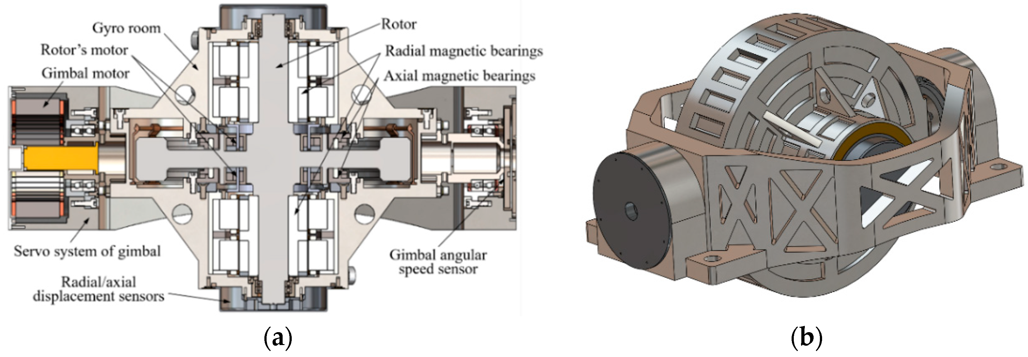
The magnetically suspended control moment gyro (MSCMG) can output large control moments by changing the direction of the angular momentum of the high-speed rotor [1,2,3]. This is one type of attitude control actuator used to modify the attitude of spacecraft with merits of micro-vibration, high precision, high reliability, longevity, and so on [4,5]. For an MSCMG, it consists of one gyroscopic room to support the high-speed rotor by magnetic bearings and one servo system of the gimbal to support the rotor’s angular moment around its orthogonal axis. Figure 1 illustrates the structure of MSCMG with one gimbal (the single-gimbal MSCMG) [6]. In the gyro room, the high-speed rotor driven by the rotor’s motor (brushless DC motor) is stably suspended by axial magnetic bearings, as well as radial ones. The axial magnetic bearings are used to control the rotor’s axial translation, while the radial magnetic bearings are used to control the rotor’s radial translation and the tilt around the radial axle. The rotor’s axial translation is measured by the axial displacement sensors, while both the radial translation and the radial tilt of the rotor are measured by radial displacement sensors; then, the magnetically suspended rotor (MSR) can be actively suspended at 5-DOF [7,8]. In the servo system of the gimbal mounted on the pedestal, the gyroscopic room driven by the gimbal motor is supported by mechanical bearings and its angular velocity is measured by a resolver or a photoelectric encoder. When the gyro room is rotated by the servo system of the gimbal, a large outputting control moment is generated.
For the MSCMG, the suspension force of the magnetic bearings is a type of elastic support with clearance, and it is intrinsically nonlinear. All these magnetic bearings used in MSCMG are permanent magnet-biased hybrid magnetic bearings, and they can be classified into radial permanent magnet-biased hybrid magnetic bearings and axial ones. There are two radial permanent magnet-biased hybrid magnetic bearings in MSCMG to control the rotor’s radial translation and the tilting around radial axes, and there are also two axial permanent magnet-biased hybrid magnetic bearings to control the rotor’s axial translation. In this paper, to simplify the expression of these magnetic bearings, we refer to the radial permanent magnet-biased hybrid magnetic bearings as radial magnetic bearings and to the axial permanent magnet-biased hybrid magnetic bearings as axial magnetic bearings. When the high-speed MSR drifts from its equilibrium position at a very small displacement or tilts at a very small angle, the gap of the magnetic bearings slightly changes. The nonlinear change of the suspension stiffness of the magnetic bearings has little impact on the magnetic suspension force, and this force can be regarded as a linear one [9]. However, when the high-speed MSR drifts from its equilibrium position at a relatively large displacement or tilts at a relatively large angle, especially when the gyroscope room is rotated by the gimbal, the gap of the magnetic bearings significantly changes, which will result in a nonlinear change of the magnetic suspension force, and the control of MSR’s suspension with high precision becomes difficult [10,11]. On the other hand, the high-speed MSR with a large angular momentum has a strong gyroscopic effect, and the rotor’s radial tilting around the X-axis or the Y-axis strongly and dynamically couples with each other [12,13]. When the gimbal rotates, the motion of the MSR couples with that of the gimbal, and some unexpected and additional disturbing torques make the dynamic behavior of the high-speed MSR more complex, and the rotor’s suspension becomes more unstable [14]. Then, the nonlinearity of the magnetic suspension force is one of the main factors that make the radial translation of the magnetically suspended rotor (MSR) be controlled with poor accuracy.
To stably control the MSR, many methods have been researched in recent years. Based on the PID control method, Wei et al. used angular velocity feedforward to enhance the suspension stability of the MSR [15]. Sun et al. and Wen et al. presented cross-feedback control methods to deal with the nutation mode of asymmetric rotors with gyroscopic effects [16,17], but these methods emphasized the stable control rather than the position accuracy of the MSR, especially when the rotor tilted at a large angle. Schuhmann et al. utilized a linear quadratic Gaussian control with an extended Kalman filter and a state feedback regulator to improve the position accuracy of the MSR [18], but since this method contains too many parameters and the related calculation is excessive, it is not convenient for engineering applications. By means of variable operating point linearization, Wei et al. established a series of corresponding magnetic force models according to the rotor’s different positions [19], but the performance of this control method is determined by factors such as the model accuracy and the rotor’s imbalance. An adaptive controller based on current stiffness estimation was presented by Ghazavi et al. to stably control the MSR [20], but the influence of the nonlinear changes of the displacement stiffness on the rotor’s position has not yet been considered.
With the development of control theory, some modern control methods such as fuzzy control, neural network control, and so on have been used to deal with these nonlinear problems in control systems. Defoy et al. used a fuzzy controller to control the magnetic bearing-rotor system in a turbine generator to improve its stability and robustness [21], but this control method cannot ensure the rotor suspended by magnetic bearings have high position precision. Chu et al. designed a neural network adaptive estimator to estimate the nonlinear changes of magnetic suspension stiffness to improve its steady-state accuracy and can control the axial translation of MSR [22], but it is difficult for this control method to control MSR’s radial translation and tilting. Chen et al. used BP neural network to adjust the parameters of the PID controller online for a 5-DOF magnetic bearing-rotor system [23], Yang et al. used feedforward neural networks to approximate the nonlinear parameters’ changing of magnetic bearing, and Sun et al. used neural networks to establish the internal model models of magnetic bearing [24], Wai et al. designed an adaptive fuzzy neural network controller to control the magnetic suspension for transmission systems [25], and Lin et al. utilized the dual integral sliding mode control (SMC) systems to regulate and stabilize the strong nonlinear magnetically suspended rotor to improve its robustness [26]. These methods mentioned above focus on how to suspend a rotor stably, but they are not able to ensure MSR has high position accuracy. Because the neural network method can be used to approximate nonlinear functions due to its ability to approximate nonlinear functions [27,28,29,30] and SMC can be used as a special nonlinear controller for its good robustness to parameter changes [31,32,33], it is a good way to use SMC combined with neural networks to control the nonlinear system in MSCMG.
With respect to the nonlinearity of magnetic suspension force in MSCMG, one of the best ways to improve the control accuracy of MSR is to improve the control accuracy of MSR’s radial translation. Based on this prototype of MSCMG, as shown in Figure 1, this paper emphasizes the control method of radial translation for MSR with high precision. To deal with the problem that the position accuracy of the rotor in MSCMG is affected by the nonlinear change of suspension force stiffness and the moving-gimbal effect, the nonlinear dynamic model of MSR is established, and the property of the magnetic suspension force is analyzed. The SMC method combined with a neural network is proposed to suspend MSR more stable and improve the control accuracy of the rotor’s position to output control moment with high precision for spacecraft. Simulations and experimental tests have been performed based on a single gimbal MSCMG with 200 N.m.s angular momentum to verify the validity and effect of this proposed control method.
2. Modelling of MSR
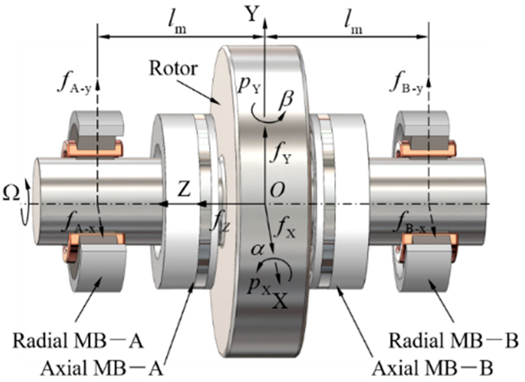
For the MSR in MSCMG, there are two 2-DOF radial magnetic bearings to control the rotor’s radial translation and tilting around radial axes, and another two 1-DOF axial magnetic bearings to control the rotor’s axial translation, then the rotor suspended by magnetic bearings is controlled five-freedom actively. To model the rotor’s dynamics, the forces and moments acting on MSR and the definition of the related coordinate system in MSCMG are shown in Figure 2.
The origin of this coordinate for the magnetic bearing-rotor system, which is also the geometric center of the rotor, is denoted by O, three axles are denoted by X-axis, Y-axis, and Z-axis, and the distance between the center of radial magnetic bearing at the A-end or B-end and O is denoted by lm, respectively. These forces generated by magnetic bearings acting on the rotor along radial direction are denoted by fX and fY; that is, these forces along radial direction generated by radial magnetic bearing at A-end are denoted by fA-x and fA-y, and that generated by radial magnetic bearing at B-end is denoted by fB-x and fB-y, and the axial forces generated by axial magnetic bearings acting on rotor along the axial direction is denoted by fZ, respectively. Similarly, these moments formed by magnetic bearings acting on the rotor around the radial direction are denoted and , respectively. The rotor’s rotary speed around Z-axis is denoted by . If the rotor’s motion occurs, the translational displacements of the rotor in X and Y directions are denoted by x and y, and the rotor’s titling angle around X-axis or Y-axis is denoted by α or β, respectively.
Based on Newton’s second law, the Euler dynamical equation, and the principle of rotor dynamics, the dynamic model of the magnetic bearing-rotor system is established as
where m is the mass of the rotor, Jr and Jz are the inertia moments of the rotor around X-, Y-, and Z-axis, respectively.
For a radial magnetic bearing with nominal clearance hm0 and bias current I0, when the rotor drifts with displacement x, the magnetic suspension force F along the drifting direction with control current i is
where μ0 is the permeability of air, N is the number of winding turns in the magnetic bearing, and AMB is the cross-sectional area of the gap between the magnetic bearings’ stator and rotor.
F = μ0N2AMB[(I0 + i)2/(hm0-x)2-(I0-i)2/(hm0 + x)2]/4
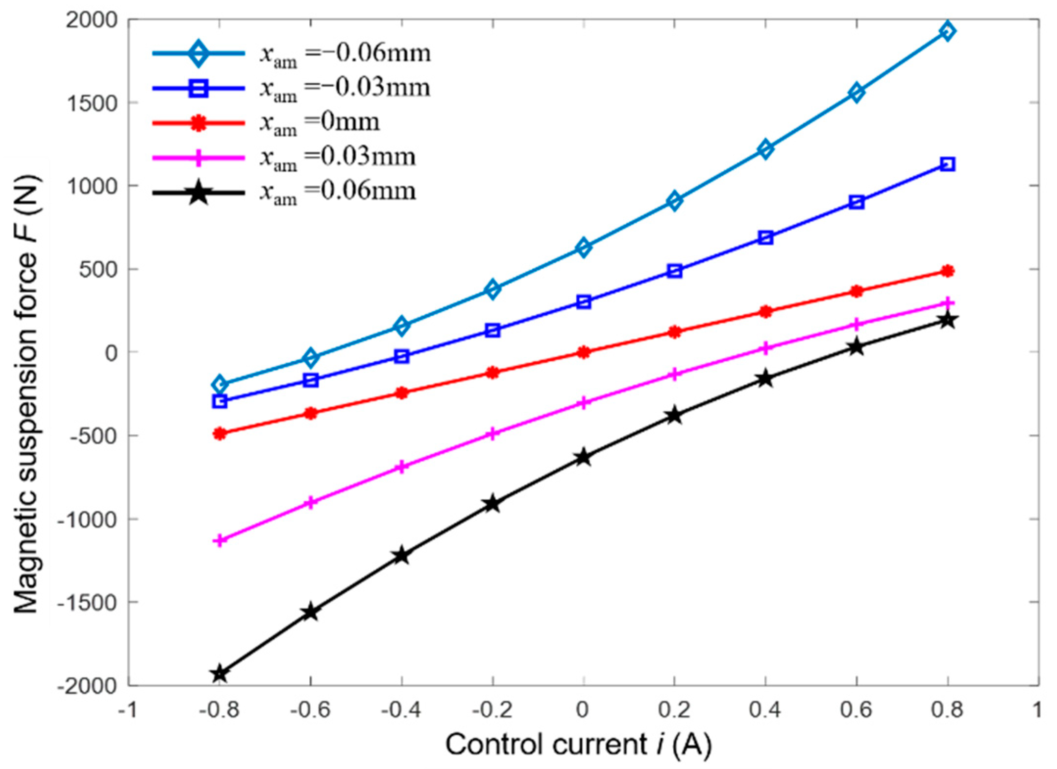
Based on the structural parameters of MSCMG as listed in Table 1, the relationship among magnetic suspension force, displacement, and control current is illustrated in Figure 3, where xam is the displacement of the rotor drifting from the equilibrium position. It can be clearly seen that F is nonlinear intrinsically. If MSR is at the equilibrium position ideally (that is, xam = 0 μm), the change of magnetic suspension force is linear. However, in the work process of MSCMG, the high-speeding rotor does not be suspended at the equilibrium position stably; it does move near the equilibrium position reciprocally. When the displacement of MSR is small (x ≤ 30 μm), the magnetic suspension force can be regarded as linear. When the rotor drifts from the equilibrium position greatly and the rotor’s displacement becomes larger (x > 30 μm), the magnetic suspension force changes nonlinearly, and obviously, the farther the rotor drifts from the equilibrium position, the higher the nonlinearity of the magnetic force.
With respect to the magnetic suspension force F as expressed in (2), we can rewrite it by Taylor expansion and ignoring these terms higher than 5 order.
In practice, the magnetic suspension force of magnetic bearing is generally expressed as a form of displacement stiffness multiplying displacement plus current stiffness multiplying control current. Set , , , , , Equation (3) can also be rewritten as
It can be seen that the model of magnetic suspension force includes not only first-order linear terms but also higher-order nonlinear ones. For the convenience of explanation, the nonlinear model of (4) is taken as
where = = is named as current stiffness, and = is the nonlinear term contained in it. Similarly, = = is named displacement stiffness with nonlinear component = + .
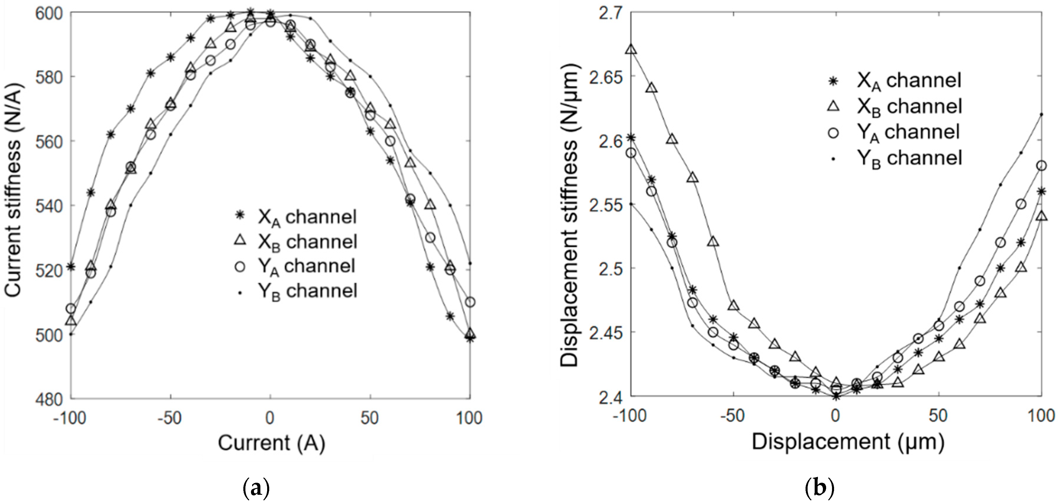
For MSR with four radial control channels in MSCMG, the control current, current stiffness, and the rotor’s displacement and displacement stiffness in XA, XB, YA, and YB channels are tested, respectively, and the fitted relationship curves between the current and current stiffness are shown in Figure 4a when the rotor is located at the center of magnetic bearings. Similarly, the fitted relationship curves between the displacement and displacement stiffness are shown in Figure 4b when the control current of the rotor is zero. It can be seen that both current stiffness and displacement are nonlinear parameters.
Set the displacement of MSR drifting from its equilibrium position is within 30 μm as in case 1 and between 30 μm and 60 μm as in case 2; the change ranges of current stiffness and displacement stiffness for MSR in MSCMG are listed in Table 2. It is found that when the rotor drifts a small displacement, the stiffness coefficient changes less and can be regarded as linear ones, while when the rotor drifts at a large displacement, the stiffness coefficient changes significantly, neither the current stiffness nor the displacement stiffness can be regarded as linear one. Additionally, affected by processing error and other factors, the rotor’s center does not coincide with that of the magnetic bearing completely, the rotor drifts, and the nonlinearity of the magnetic suspension force increases significantly; it is necessary to take these nonlinearities of magnetic bearings into consideration to control MSR stably with high precision.
Considering the uncertainty of disturbance , which may be caused by odd harmonic vibration, unmodeled dynamics of MSR, and so on, the equations of radial translation of MSR in (1) becomes
where and present the components of disturbance in the X or Y direction, and present the control current in X or Y channels of magnetic bearings, respectively.
Because the form of the dynamic equation in the Y channel is exactly similar to that in the X channel, the dynamic equation in the X channel is taken as an example to analyze the control properties of MSR.
Set , , , Equation (7) can be expressed as a second-order nonlinear uncertain system
where , , , the disturbance has upper bound D and .
Based on this previous analysis, it is found that when MSR drifts from its equilibrium position at a large displacement, the nonlinear variation of the stiffness coefficient is significant, and the accuracy of MSR’s position will decrease; then, it is necessary to design a nonlinear control method to improve the position accuracy of MSR to improve the accuracy of CMG’s outputting control moment.
3. Design of Neural Networks SMC
3.1. Radial Basis Function (RBF) Neural Network
As one of the nonlinear control methods, SMC can constantly adjust the structure of the control system according to the changes of state variables, such as errors and their derivatives, to make the system move near the predetermined state trajectory with small amplitude and high frequency (this movement is named sliding mode). SMC has advantages such as fast response speed, insensitivity to parameter perturbation and external interference, and so on, and can improve the robustness of the system. For the nonlinear system of MSR, there does exist the uncertain influence of stiffness coefficient. To improve the robustness of the system and eliminate the influence of chattering, it is a good way to adopt the exponential reaching law in SMC to regard the nonlinear change of the displacement stiffness and the uncertain disturbance as uncertain disturbance acting on this system. The adaptive algorithm used to estimate the current stiffness coefficient can adapt to the dynamic changes of the control object and disturbance by modifying its own characteristics to improve the compensation accuracy of the control law for suspension force. The neural network is one kind of algorithmic mathematical model that can process information in a distributed and parallel manner. By imitating the neural network system of animals and adjusting the connection relationships between various neural nodes, it can efficiently and intelligently process information. For a nonlinear system, there are not only high-order terms whose accurate models are difficult to be established but also some uncertain disturbances such as unmodeled dynamics and others, then the neural networks can be used to approximate these nonlinear uncertain models.
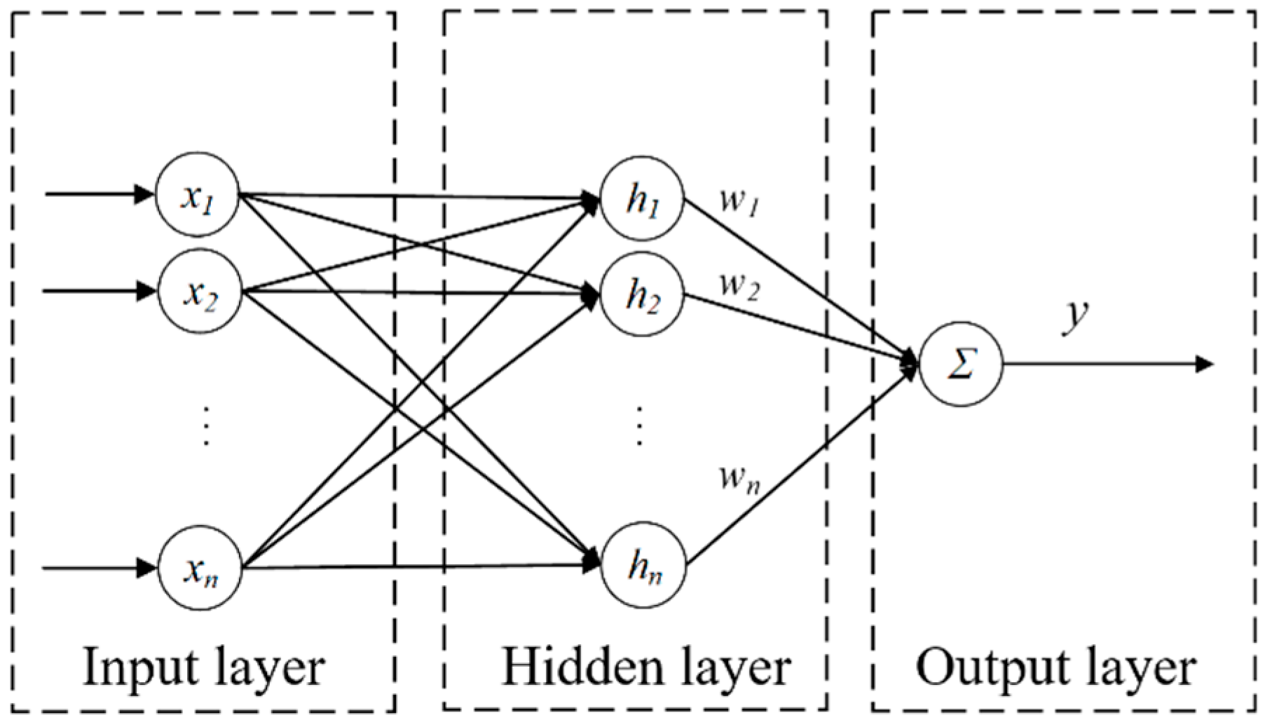
Radial basis function (RBF) is one kind of real-valued function, and its value depends only on the distance from its origin point or center, that is , which means that any function satisfying this characteristic belongs to RBF. RBF neural network has fast data processing speed, strong self-learning ability, and good mapping ability to continuous nonlinear systems. The structure of the RBF neural network, as shown in Figure 5, consists of an input layer, a hidden layer, and an output layer. The data information to be processed enters the neural network from the input layer; each operation unit in the hidden layer is composed of RBFs, and there is a corresponding weight between each neuron and output function individually. In the output layer, the linear operation with the weighting function is finished, and the result y is output.
The algorithm of the neural network based on RBF is
where is input variables, is the width of the Gaussian function, and it is generally a suitable positive scalar, n is the number of nodes in the hidden layer. is the central vector of each neuron’s Gaussian function, and its value should cover the change range of input variables. The closer is to the input value, the more sensitive the function is to the changes in input.
If is the connection weight of each layer, then the output function of the network containing weight function is
The selection of the connection weight and Gaussian function of the neural network has an important impact on the control effect of the system. The approximation effect of the neural network is related to the parameters such as the connection weight , , and in Gaussian function and other design parameters.
3.2. Design of Neural Networks SMC
The magnetic suspension force has multivariable nonlinear characteristics; it is difficult to control the MSR through linear control methods with high-precision positions. SMC provides an effective control method for nonlinear systems with uncertainties, and the neural network algorithm has a strong approximation ability to nonlinear functions. Then, the neural networks combined with SMC can effectively deal with the chattering problem and improve the position accuracy of MSR. With respect to the model of magnetic suspension force , is used to present the total uncertainty, including displacement stiffness and interference, and is used to present the reciprocal of current stiffness; Equation (8) can be rewritten as
where satisfies the condition that , and satisfies the condition that .
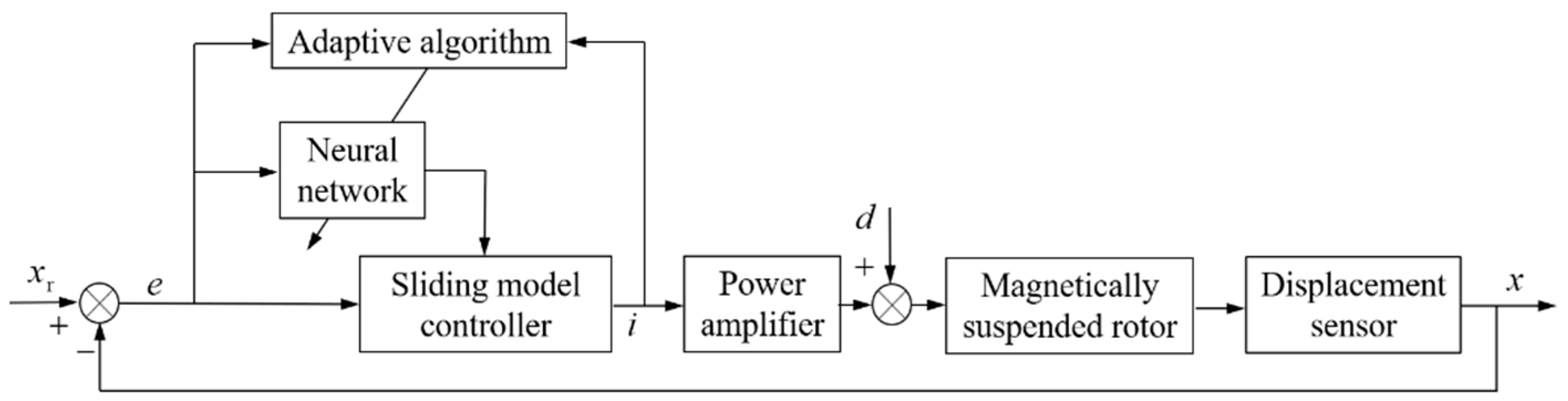
In the neural network SMC, as shown in Figure 6, x is the rotor’s actual position, xr is the rotor’s reference position, d is the disturbance, e is the rotor’s position error, and i is the control current. In this neural network SMC, the neural network is used to approximate the nonlinear function in the control law, the adaptive algorithm is used to adjust the weights in the neural network, and the control current i is outputted from this sliding mode controller to control MSR with the high-precision position.
Set the position error e = xr − x as the controller input; the sliding surface can be designed as
where .
Then the following equation can be obtained
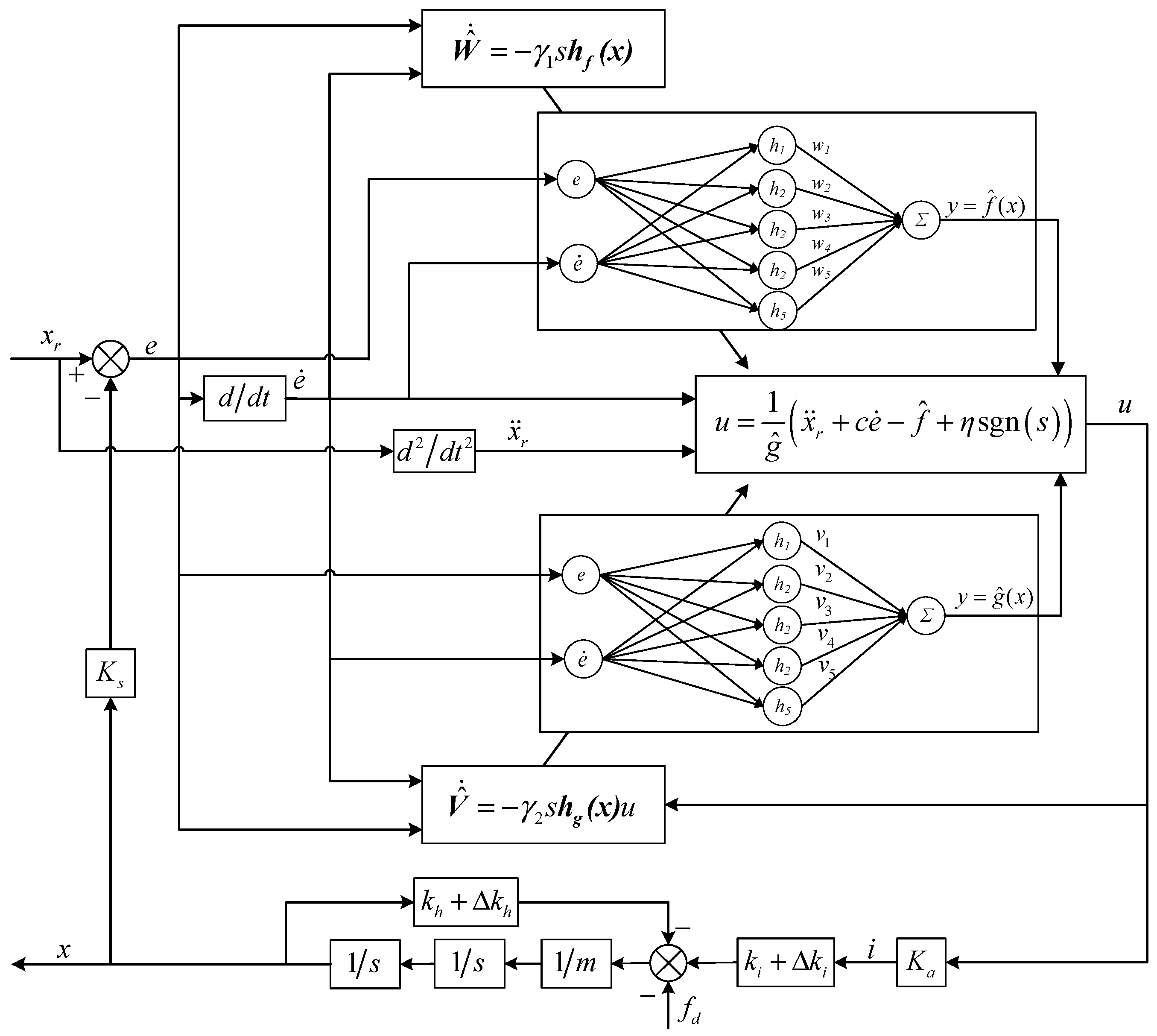
where f and g are nonlinear functions related to displacement stiffness or current stiffness, respectively, both f and g can be approximated by RBF neural network.
Where is the input of this neural network SMC and , J is the jth node in the hidden layer and, here, j = 5, is the output of the radial basis function, W and V are ideal weights of neural networks SMC, and are the approximation errors and 、 .
Because f and g are the ideal output of the RBF neural network, the actual f and g outputted from RBF neural network are replaced by the estimated and highly approximated and , respectively.
where is the actual weight for , and is the actual weight for , respectively.
The control law can be derived from (13)
where approaching rate , and D is the upper bound of interference.
3.3. Weight Update and System Stability Analysis
Keeping the control system of MSR stable is fundamental to controlling MSR with a high-precision position, and the stability of the neural network SMC algorithm is closely related to the weight adjustment process of the nonlinear function in the control law. Analyzed the stability of the MSR system by Lyapunov functions, the rules of updating the network weights can be obtained based on adaptive algorithms.
Substituted (12) into (13), it is obtained
where , , , .
Define the Lyapunov function of the closed-loop system as
where adaptive learning rates and .
Taking the derivative of L and substituting (18) into it, we can obtain
Using adaptive algorithms to update network weights
Substituted (20) into (19), it is obtained
Because these approximation errors and can be limited sufficiently small, if , then . If there does exist satisfying and , then . Because , so , and are bounded. For an actual rotor system, both the rotor displacement and its derivatives are continuously bounded; the rotor position error and its derivative are also bounded and converge to zero when the time approaches infinity according to the LaSalle invariance principle, namely , , then , . In addition, according to these expressions of the control law of SMC, neural network output and , adaptive law and , all of them are bounded. The control variables in MSR are all bounded, so the rotor control system is gradually stable. Figure 7 is the control block diagram of a radial control channel with neural network SMC for MSR.
4. Simulation and Experimental Research
In this experimental setup with MSCMG, as shown in Figure 8, the radial magnetic bearing for MSCMG is a permanent magnet-biased hybrid magnetic bearing, and the X and Y directions are separately controlled by these coils in magnetic bearings.
To approximate the discrete model y(k) = u(k)3 + y(k−1)2/[1 + y(k−1)3], the structure of the neural network has a 2-5-1 form, that is to say, there are two input signals, five neurons in a hidden layer, and one outputting. The optimized parameters b and c for the Gaussian function are and according to the design rules of the Gaussian function. The parameters kp, ki, and kd for general PID control are optimized and tunned by nonlinear least squares function lsqnonlin() and least square indicator in MATLAB software. The initialization parameters and optimization results are listed in Table 3, and the control parameters of neural network SMC are listed in Table 4, where W0 and V0 are the initial weight values for weights W and V.
4.1. Radial Translation Control of MSR without Gimbal Moving
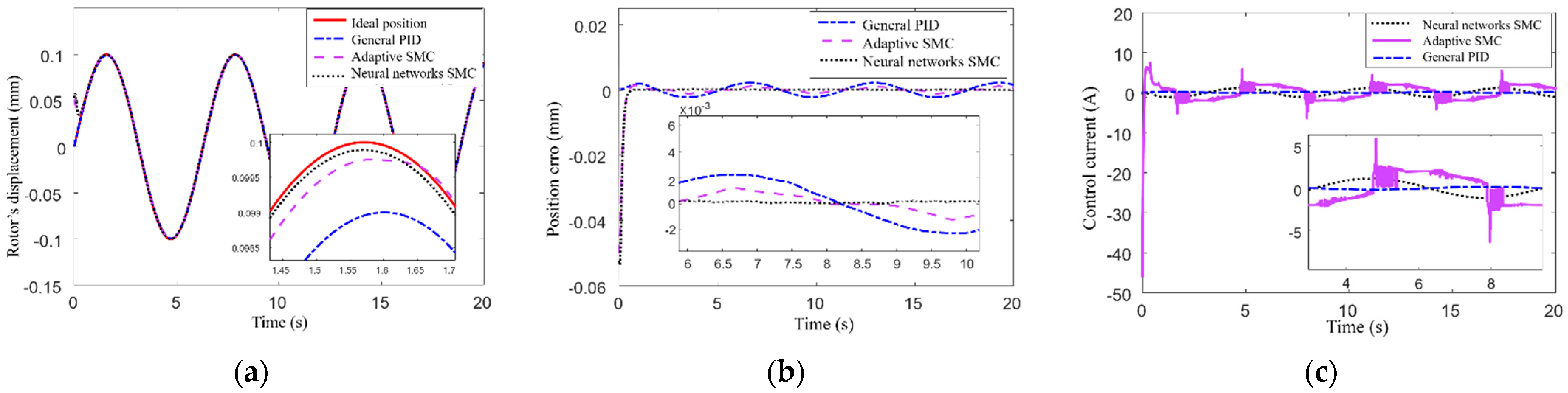
According to the structural parameters of MSCMG as listed in Table 1, the inputting displacement of MSR, which is a sinusoidal signal and set as 0.1 sin (1.5 t) (mm), and the simulation results are shown in Figure 9 when the simulation time is 20 s, where the solid line presents the given position of MSR, the rotor’s position controlled by general PID is presented by the dotted line, that controlled by adaptive SMC is represented by the dotted line, and that controlled by neural network SMC is represented by the dotted line, respectively. Figure 9a,b illustrate the rotor’s positions and the related positional errors controlled by three control methods, respectively. It can be seen that the neural network SMC converges rapidly when t = 0.3 s, and the steady-state error is only 0.0001 mm; Compared to neural network SMC, the general PID has a shorter response time, but from the locally enlarged image, it can be seen that the control effect of general PID on sinusoidal input is not ideal, the position error is about 0.003 mm. When t = 0.3 s, the position error of MSR controlled by neural network SMC decreases to 10% of that controlled by the adaptive SMC. Figure 9c shows the time-varying curves of control signals for three methods. It can be seen that the neural network SMC not only can reduce the control current but also can improve the rotor position accuracy; furthermore, the neural network SMC can not only prevent overcurrent damaging the control circuit but also reduce the consumption of control power. The current fluctuation in the first two seconds implies the adjustment process of the controller, and the subsequent smoothing control current curves indicate the output of the control system is stable. This comparison verifies that the control effect of neural network SMC is better than that of general PID control and adaptive SMC when the input signal is sinusoidal for MSCMG without the gimbal moving.
In the control law of SMC, there are two nonlinear functions f(x) and g(x) need to be approximated by a neural network algorithm. This algorithm can adjust the weight value online according to the position error of MSR and continuously improve the approximation accuracy of the nonlinear function to adjust the control current in real-time; then, the position accuracy of MSR is improved accordingly. Figure 10a is the adjustment process of weight value W in the neural network to approximate the nonlinear function f(x), Figure 10b is the adjustment process of weight V in the neural network to approximate the nonlinear function g(x). It can be seen that there is a period of rapid adjustment after the weight value is initialized, and the nonlinear function weight value adjustment process is gradually consistent with the trend of the input signal within 1 s, which indicates that the algorithm has the ability to quickly adjust and accurately track the input. The weight adjustment range of these two nonlinear functions changes regularly in different intervals. The fact that the change ranges of these two functions differ with the change of input reflects that the values of both displacement stiffness and current stiffness are different.
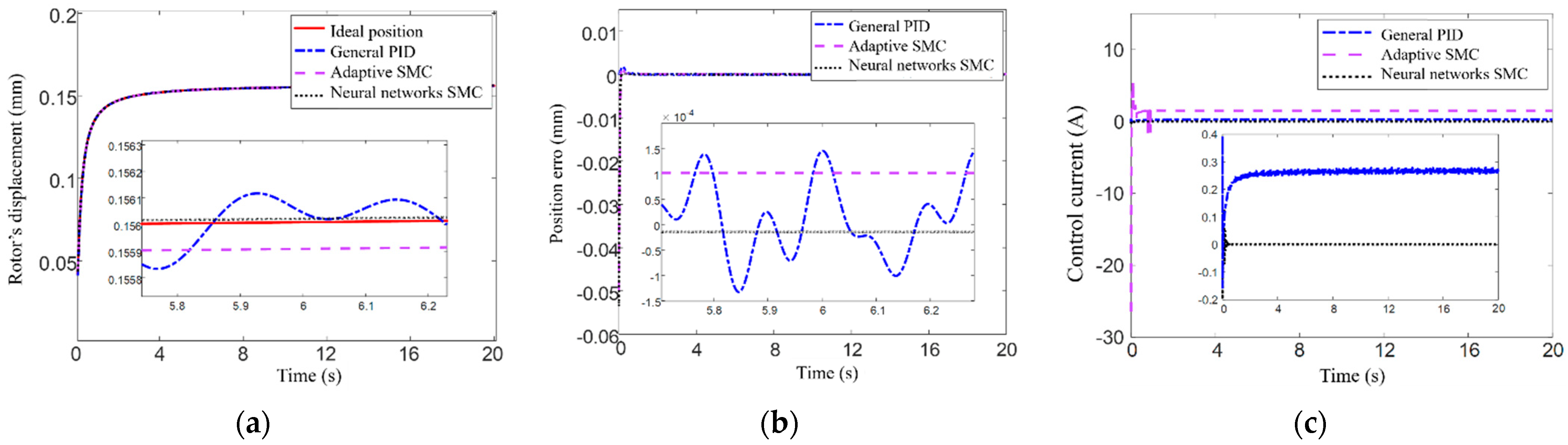
Set the step signal input into the rotor’s translation direction as 0.1 arctan(20 t), and simulation results of the control position for MSR are shown in Figure 11, where the simulation time is 20 s, the given position of the rotor is presented by the solid line, the position of the rotor controlled by general PID is presented by the dotted line, that controlled by adaptive SMC is presented by the dotted line, and that controlled by neural network SMC is presented by the dotted line, respectively. Figure 11a illustrates the control effect of the three methods on rotor position, and Figure 11b illustrates the error comparisons for these three methods. It can be seen that the neural network SMC can adjust rapidly at the initial time and will reach the steady state after t = 0.2 s, the steady-state error is only 10 × 10−5 mm, its control accuracy is better than that of adaptive SMC, and its steady-state error is only about 5% of that of general PID. For the general PID, there exists a high-frequency oscillation in the rotor’s displacement and a fluctuation in the control process with a relatively large amplitude, and the related error is up to 0.001 mm.
Figure 11c shows the control signals’ changing curves of three methods with time. It can be seen from these figures that the control signal of the adaptive SMC rises sharply at time t = 0, what is the response of the control system to the step signal from 0 to 0.1, and the rising amplitude is greater than the peak value controlled by neural network SMC. Subsequently, the control system quickly adjusted, and the trend of the control signal was roughly the same as that of the input signal. After the system reached a steady state, the control signal of general PID still had small fluctuations, while the control signal of the neural network SMC approached zero after the system reached a steady state. This indicates that neural network SMC can adjust the control signal in real-time based on the changes of input; it can reduce the control power consumption and effectively improve the position accuracy of MSR.
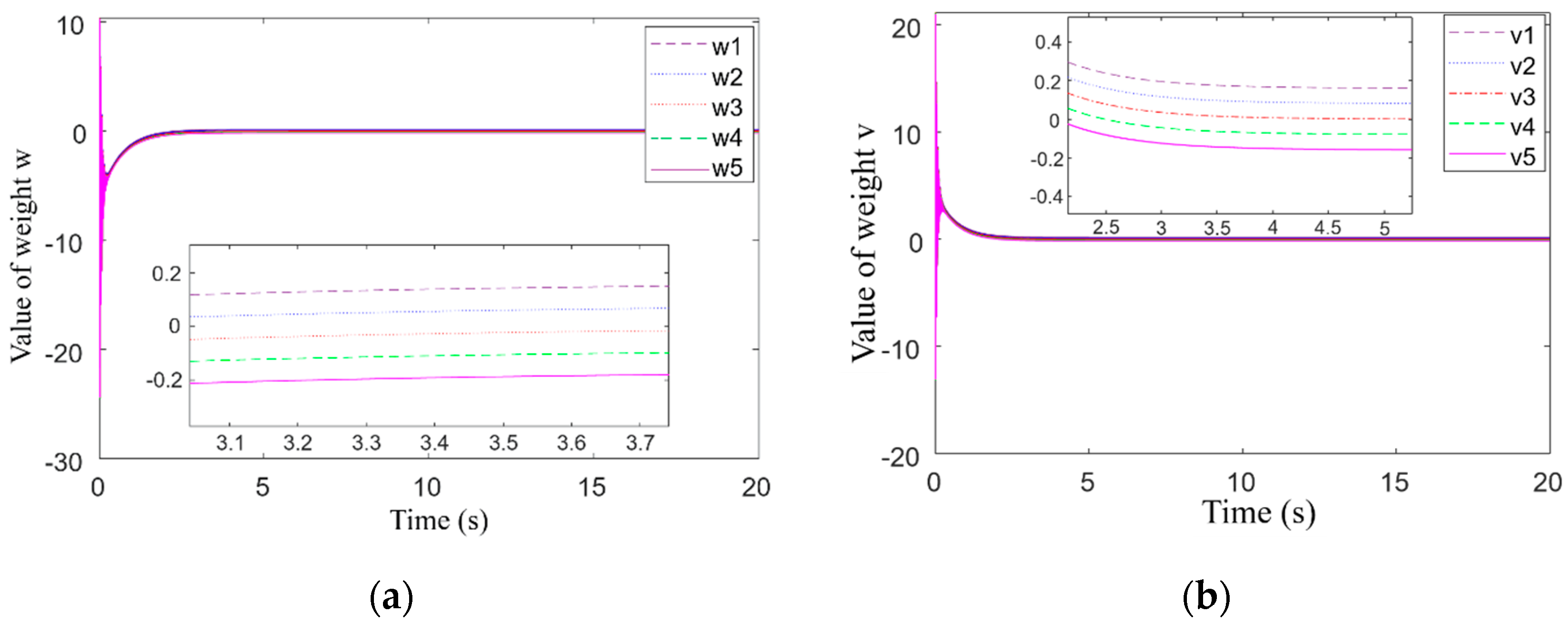
Figure 12 shows the weight adjustment process of the neural network algorithm to approach the nonlinear function when the step signal is input. Figure 12a illustrates the adjustment of t weight w to approximate the nonlinear function f(x), and (b) illustrates the adjustment of the weight v to approximate the nonlinear function g(x). It can be seen from Figure 12 that when the input signal occurs a step jumping, the adjustment of the weights oscillates accordingly, there is a slow adjustment process after t = 0.5 s, and the adjustment of the weights tends to be stable when t = 3 s. This process indicates the relationship between the weight adjustment and the input signal function. Since the input signal is an arctangent function, its step response process is not an abrupt one and gradually tends to a final value of 0.1 after a sharp rise. Therefore, the weight adjustment process of the nonlinear function not only indirectly reflects the change of the input signal but also indicates that the control system can adjust the control law online based on the input signal to make the control current respond to changes in input in time to ensure the position accuracy of MSR.
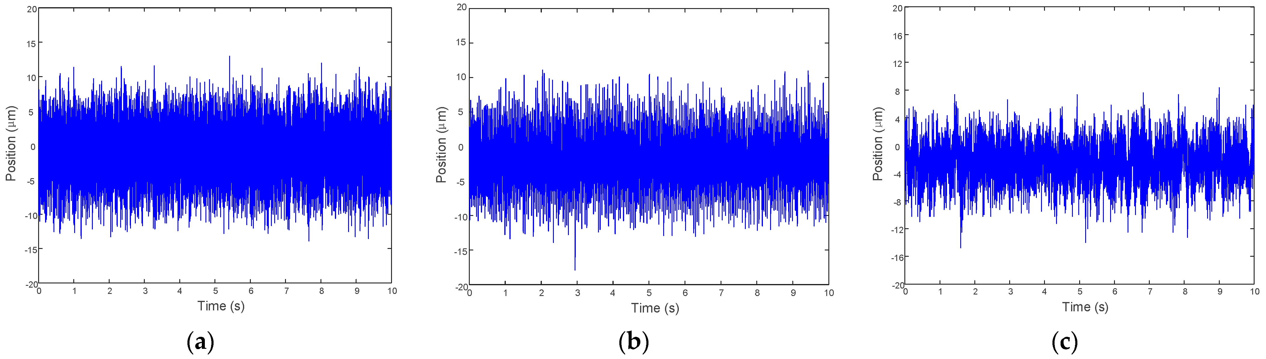
In order to verify the effectiveness of the neural network SMC to improve the rotor position accuracy when the gimbal of MSCMG is not rotated, the rotor’s speed is 1200 rpm; these experimental tests of the rotor’s radial translation in one channel controlled by general PID, adaptive SMC, and neural network SMC, which are performed according to simulation conditions. The tested position curves in one channel for three control methods are shown in Figure 13, respectively. From Figure 13a, it can be seen that the average translational displacement of the rotor controlled by general PID is 10 μm. As shown in Figure 13b, the adaptive SMC does not significantly improve the rotor position accuracy yet. For the neural network SMC, the average rotor translation displacement, as shown in Figure 13c, is up to 5 μm, and the position accuracy is improved by 50% compared to that of general PID. It is clear that the neural network SMC can effectively improve the rotor’s position accuracy of radial translation when the gimbal of MSCMG is static.
4.2. Radial Translation Control of MSR with Gimbal Moving
To output the control moment, the gimbal of MSCMG must be rotated. Generally, the maximum rotary speed of the gimbal for MSCMG is ± 15°/s; namely, the maximum angular velocity of the gimbal is ±1.6328 rad/s. To simulate the impact of gimbal rotation and other uncertain disturbances on the suspension stability and position accuracy of the rotor with a rotary speed of 15,000 rpm, both the tilting forces and interference force are introduced to simulate odd harmonic disturbances and uncertain ones that exist during actual operation. The interference is set as d(t) = 0.2 sin(1.6328 t) + 0.1 sin(1570 t) + 0.05 sin(4710 t) + random(σ2 = 0.1) (N), where 0.2 sin(1.6328 t) is the tilting force generated by the gimbal moving and will make the rotor tilting around its radial axes, 0.1 sin(1570 t) is the fundamental frequency unbalance vibration, 0.05 sin(4710 t) is the triple frequency one, and random(σ2 = 0.1) is a random interference acting on MSR, respectively.
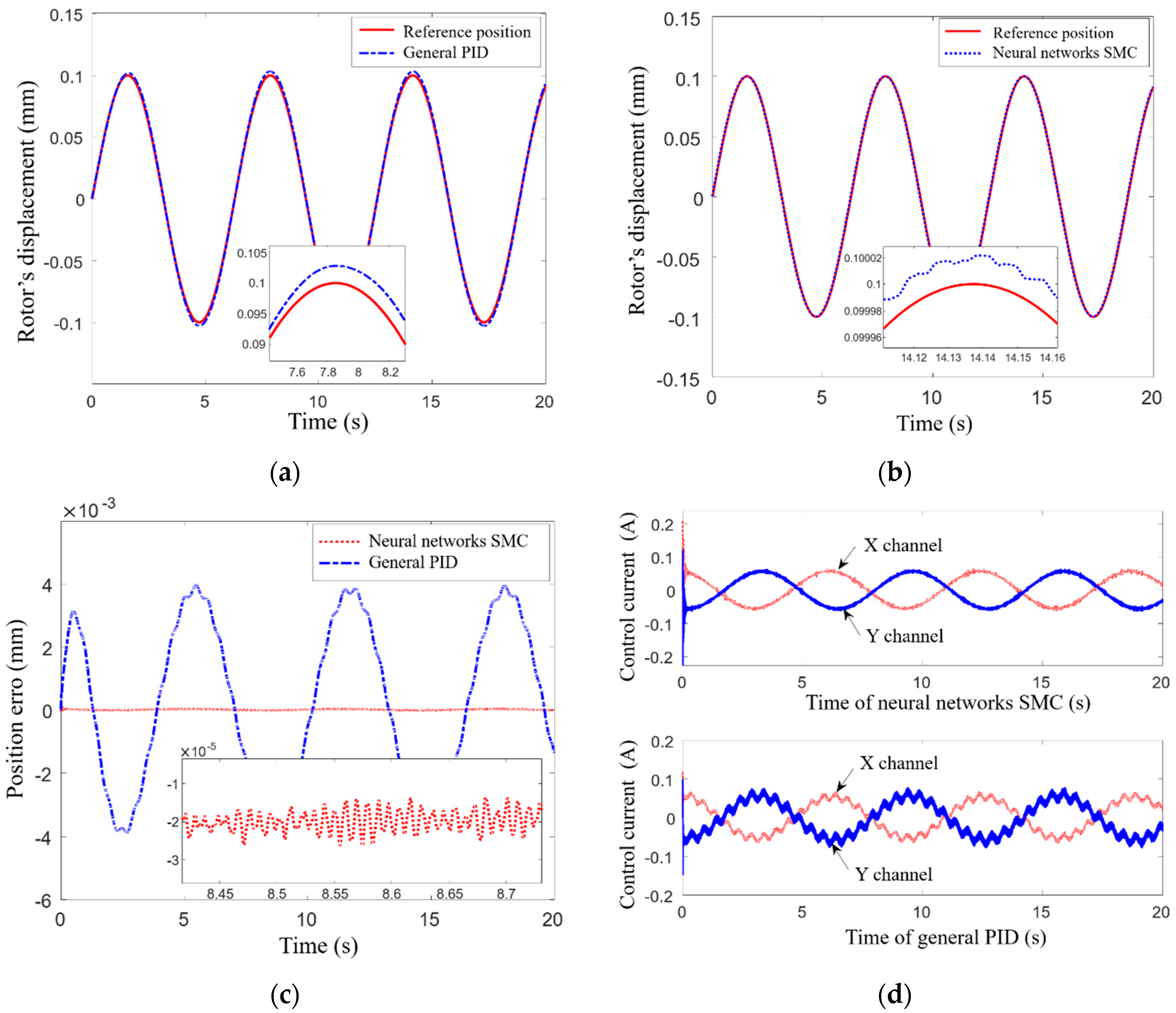
When the input signal is a sinusoidal one, the position of MSR controlled by neural network SMC and PID plus cross-feedback control method is shown in Figure 14, where the solid line represents the given position, the dotted line represents the rotor position controlled by the neural network SMC, and the dotted line represents the rotor position controlled by PID plus cross-feedback control. Figure 14a illustrates the rotor position controlled by PID plus cross-feedback control; Figure 14b illustrates that controlled by neural network SMC. It can be seen that the position accuracy of MSR controlled by neural network SMC is up to 99.98% while that controlled by PID plus cross-feedback control is 95%; it is clear that the neural network SMC has a better control effect on improving the position accuracy of MSR when MSR is affected by gimbal rotation and other uncertain disturbances. From Figure 14c, it can be seen that when the influence of gimbal rotation and other uncertain disturbances act on MSR, the position error controlled by neural network SMC is only 0.5% of that controlled by PID plus cross-feedback control, the neural network SMC can effectively suppress external interference and improve the robustness of MSR. The control currents generated by neural network SMC and PID plus cross-feedback control are illustrated in Figure 14d, where the dashed line represents the changes of control current in X channels, and the solid one represents that in Y channels, respectively. We can find out that the fluctuation of control current generated by neural network SMC is significantly smaller than that generated by PID plus cross-feedback method, so the neural network SMC can suppress this kind of disturbance well. It also can be seen that the change period of the control current is roughly the same as that of the input signal; the control system can respond to the changes in the input signal in time to ensure the control signal controls the magnetic bearing immediately, then the position accuracy of MSR can be improved accordingly.
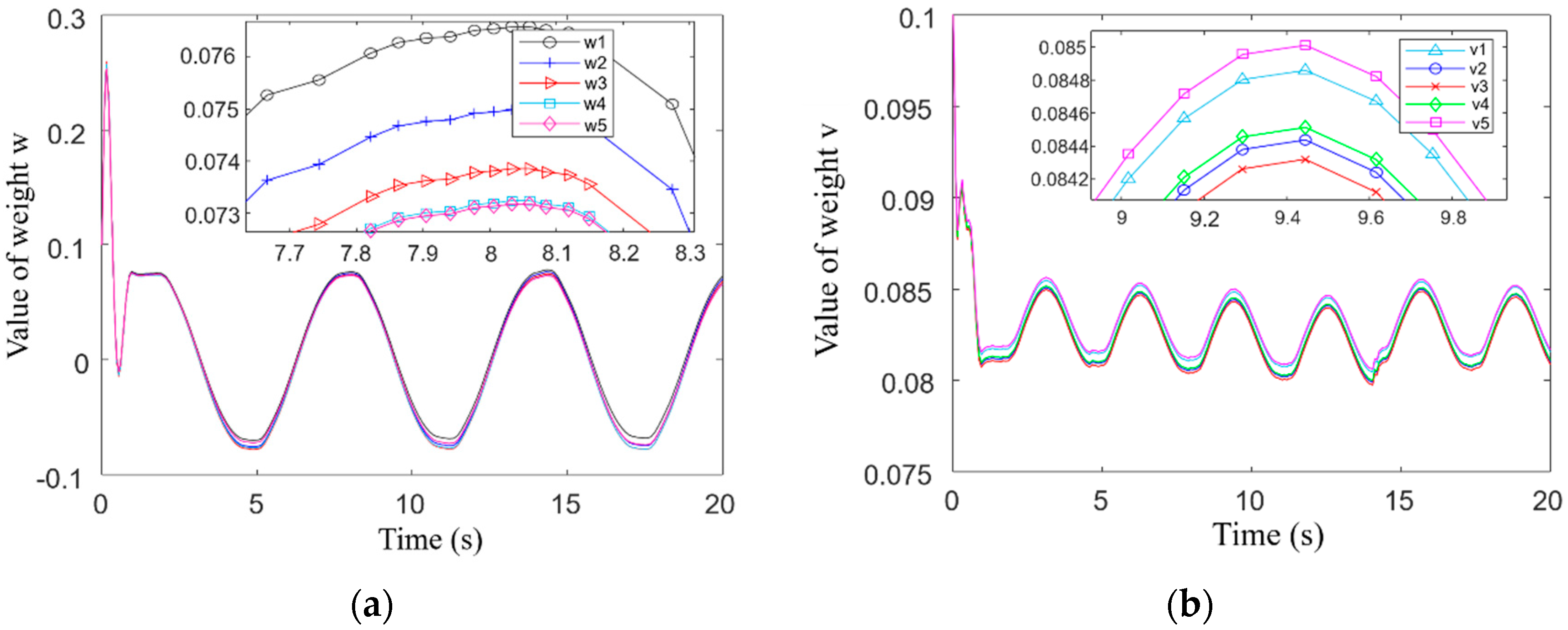
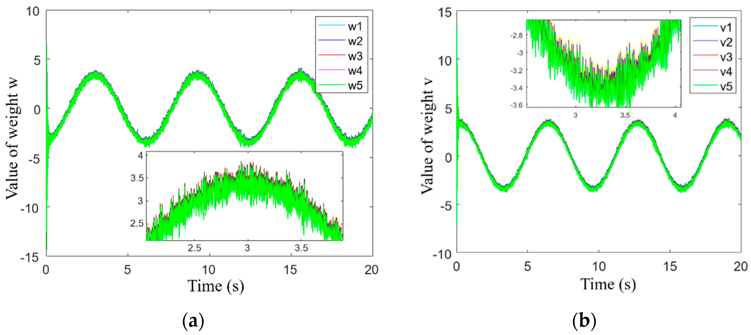
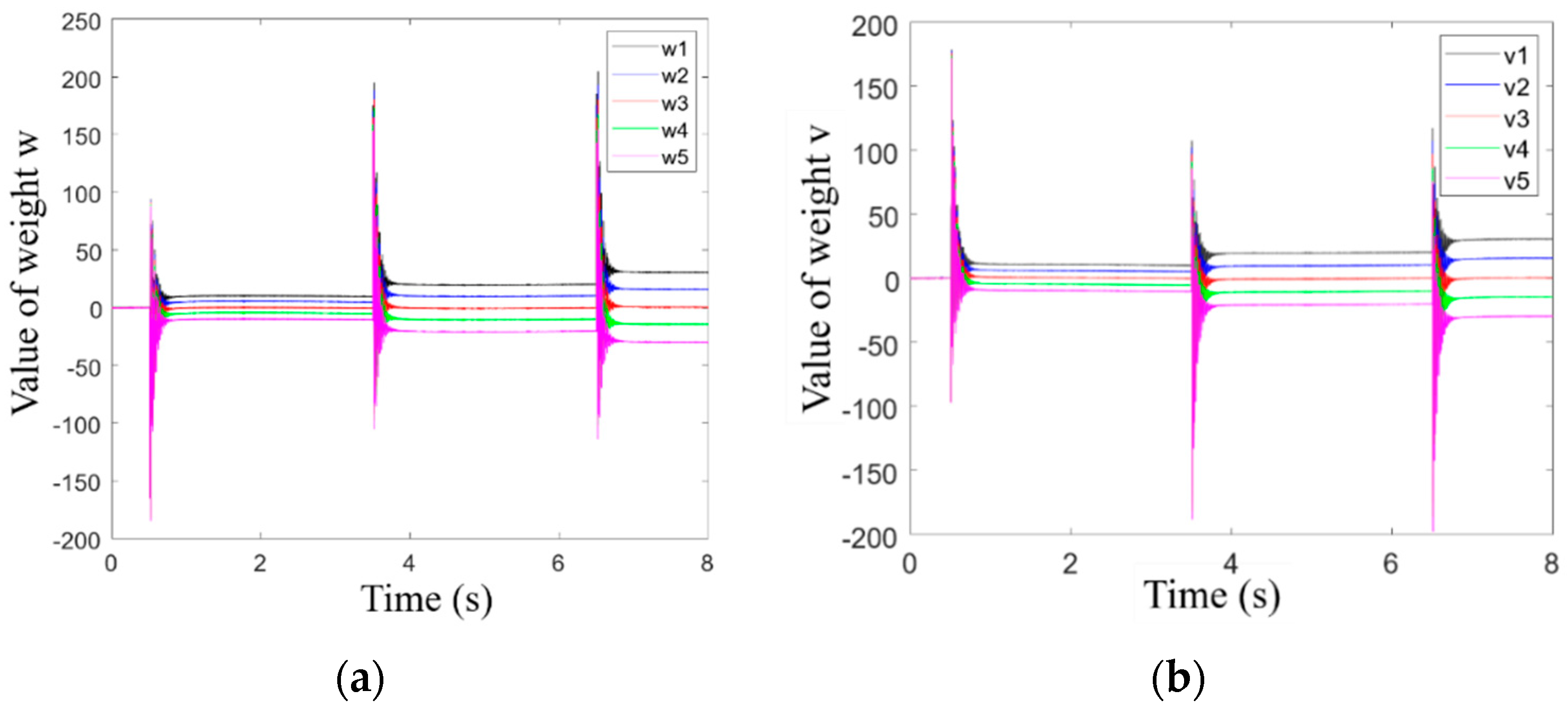
When the gimbal rotates and MSR is affected by uncertain disturbances, the difficulty of controlling the radial translation of MSR will increase significantly, and the weight adjustment process to approximate the nonlinear function in the control law can indirectly reflect the ability of MSR to maintain high robustness and high position accuracy. Because the control method of radial translation in the X channel is the same as that in the Y channels, and the weight adjustment processes for weights w and v are identical, the adjustment processes of weights w and v in the neural network algorithm to approximate the nonlinear function in X channel with sinusoidal input is shown in Figure 15. Figure 15a illustrates the adjustment process of weight w to approximate nonlinear functions fn(x), and Figure 15b illustrates that of weight v to approximate nonlinear functions . It can be seen that when the tilting torque and interference are introduced, the trend of the adjustment process for weight w is roughly the same as that for weight v. In the partially enlarged drawing, we can find out that there does exist some high-frequency oscillation in the weight adjustment process. We also find out that these high-frequency oscillations indicate the influence of odd multiple-frequency interference on the control system, and the online adjustment process of weights w and v can respond to high-frequency interference by approximating nonlinear functions in neural network SMC.
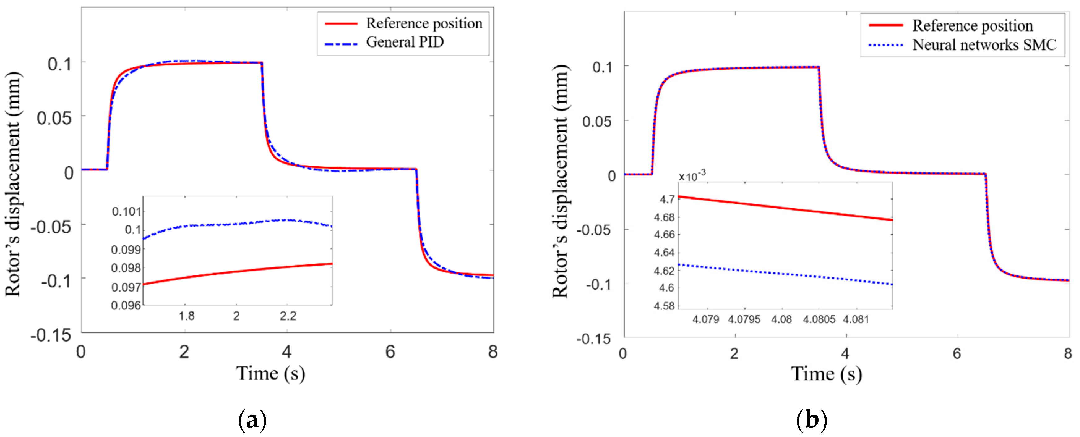
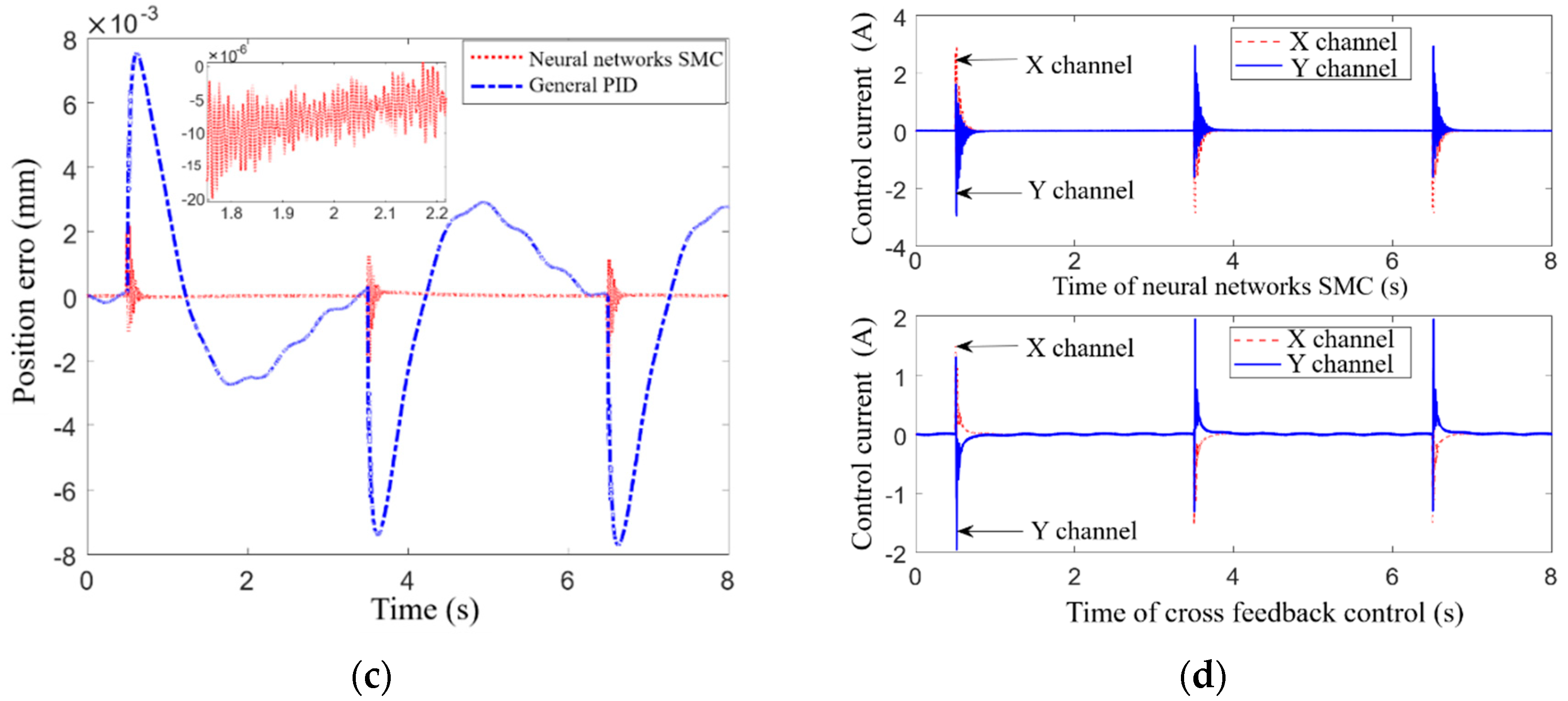
When the input signal is a step one, the rotor’s positions controlled by neural network SMC and PID plus cross-feedback method are shown in Figure 16, where the given position of MSR is represented by a solid line, the rotor’s position controlled by neural network SMC is represented by the dotted line, and that controlled by PID plus cross-feedback control is represented by the dotted line, respectively. Figure 16a illustrates the rotor’s displacement controlled by PID plus cross-feedback method, and Figure 16b illustrates that controlled by neural network SMC. It can be seen that the position error of MSR controlled by neural network SMC is only 7 × 10⁻⁵ mm, which is only 1% of the that controlled by PID plus cross-feedback method; it is clear that this presented neural network SMC has a better control effect on improving the position accuracy of MSR when the gimbal is rotated and other uncertain disturbances acting on it. The comparison of the rotor’s position error controlled by neural network SMC and PID plus cross-feedback method is shown in Figure 16c, it can be found from the partially enlarged drawing in it that the rotor’s position error controlled by neural network SMC can quickly converge after a step occurs in the input signal, and the neural network SMC method also has a better effect on suppressing abrupt disturbance.
Figure 16d illustrates the control currents controlled by neural network SMC and PID plus cross-feedback method; the control signal in the X channel is represented by the dotted line, and that in the Y channel is represented by the solid line, respectively. It can be seen that these two control signals both have an obvious adjustment when the inputting signal steps and the adjustment time of the control current for each step of inputting signal is about 0.3 s, which indicates that the response of the control system is fast. Both the frequency and amplitude of the control signal’s oscillation controlled by neural network SMC are slightly larger when the step signal occurs, so the neural network SMC can control MSR’s position with higher precision when the gimbal of MSCMG rotates, and other uncertain disturbances act on MSR.
When the rotor is affected by abrupt disturbance, the displacement stiffness and current one of MSR will have obvious nonlinear changes, and the nonlinear function in the control law of neural network SMC will change accordingly. Regarded the step change process of the input signal as the process of applying interference torque suddenly, the adjustment process of weights in the neural network algorithm to approximate the nonlinear function in X channel is shown in Figure 17, where the adjustment process for weight w to approximate nonlinear functions fn(x) illustrated in Figure 17a, and weight v to approximate nonlinear functions illustrated in Figure 17b, respectively. It can be seen that when the tilting torque and other uncertain disturbances are introduced, the weight adjustment process will oscillate with large amplitude and high frequency if the input signal steps, but it can converge quickly within 0.3 s; this is a timely adjustment made by the control algorithm according to rotor’s position error. All these simulation results prove that the neural network not only has the ability to approximate the nonlinear functions with high precision but also can update its weights online rapidly.
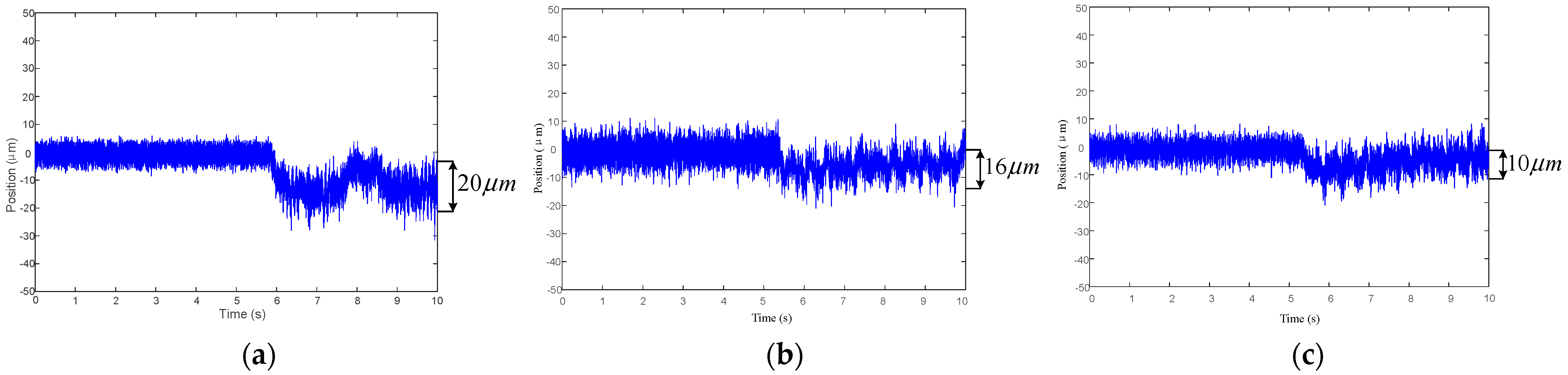
In order to verify the position accuracy of MSR when the gimbal of MSCMG rotates and other uncertain disturbances act on MSR, the experimental test of MSR’s displacements controlled by different control methods was performed when the rotary speed of MSR is 1000 rpm, the gimbal of MSCMG is accelerated from rest at t = 5 s, and its average angular velocity is 1.6328 rad/s, Figure 18 illustrate the tested displacements of MSR in X channel controlled by general PID, adaptive SMC, and neural network SMC, respectively. It can be seen that the average displacement of MSR controlled by general PID is 20 μm and that controlled by adaptive SMC is 16 μm, which is improved by 20% of that controlled by general PID. Furthermore, the average displacement of MSR controlled by neural network SMR is only 10 μm, which is improved by 50% compared to that controlled by general PID. At time t = 10 s, the MSR becomes stable, and it is closer to its own equilibrium position. These experimental results show that the neural network SMC can effectively improve the position accuracy of MSR when the gimbal of MSCMG rotates, and other uncertain disturbances act on MSR. Simulation and experimental results indicate that the neural network SMC can effectively improve the position accuracy of MSR in MSCMG. On the other hand, with respect to the displacement curves of MSR, we do find out some obvious high-frequency oscillations in the experimental test and simulation, and the position error in the experimental test is larger. The reason for this phenomenon may be that there exists some uncertain interference, sensor noise, and other factors still acting on MSR in actual systems.
5. Conclusions
With respect to the nonlinearity of magnetic suspension force for MSR, the influence of nonlinear changes in displacement stiffness and current one on the magnetic force are analyzed, a second-order nonlinear uncertain system model for MSR is established, and a neural network SMC is designed to control rotor’s radial translation with high-precision. When the gimbal of MSCMG does not rotate, the tested average rotor translation displacement controlled by neural network SMC is up to 5 μm, and the position accuracy is improved by 50% compared to that of general PID, so the presented neural network SMC can effectively improve the position accuracy of MSR and has the ability to suppress disturbance; When the gimbal of MSCMG rotates, and the rotor is disturbed by uncertain disturbances, the tested average displacement of MSR controlled by neural network SMR is only 10 μm, which is improved by 50% compared to that controlled by PID plus cross-feedback method, so the presented neural network SMC can not only suppress these disturbances caused by the moving of gimbal and other uncertain factors but also improve the position accuracy of MSR. These results of simulation and experiments demonstrate that this presented neural network SMC can effectively improve the control accuracy of MSR’s radial translation for MSCMG to output control moment with high precision for spacecraft.
Author Contributions
Conceptualization, J.T. and X.C.; methodology, X.C.; software, X.C.; validation, M.Z. and X.Z.; formal analysis, X.C.; investigation, J.T. and X.C.; resources, X.C.; data curation, J.S.; writing—original draft preparation, J.T. and X.C.; writing—review and editing, M.Z.; visualization, X.C.; supervision, J.T.; project administration, J.T.; funding acquisition, J.T., J.S. and X.Z. All authors have read and agreed to the published version of the manuscript.
Funding
This work was supported by Beijing Municipal Natural Science Foundation (Grant No. 4222048), National Natural Science Foundation of China (Grant No. 62073010, 52075017, and 62122009), and Ningbo Nature Science Foundation (Grant No. 2021J011).
Institutional Review Board Statement
Not applicable.
Informed Consent Statement
Not applicable.
Data Availability Statement
Not applicable.
Conflicts of Interest
The authors declare no conflict of interest.
References
- Qu, Z.; Zhang, G.; Meng, Z.; Xu, K.; Xu, R.; Di, J. Attitude maneuver and stability control of hyper-agile satellite using reconfigurable control moment gyros. Aerospace 2022, 9, 303. [Google Scholar] [CrossRef]
- Geranmehr, B.; Vafaee, K.; Nekoo, S. Finite-horizon servo SDRE for super-maneuverable aircraft and magnetically-suspended CMGs. Proc. Inst. Mech. Eng. Part G J. Aerosp. Eng. 2016, 230, 1075–1093. [Google Scholar] [CrossRef]
- Hu, Y.; Geng, Y.; Biggs, J. Simultaneous spacecraft attitude control and vibration suppression via control allocation. J. Guid. Control Dyn. 2022, 44, 1853–1861. [Google Scholar] [CrossRef]
- Li, J.; Liu, G.; Zheng, S.; Cui, P.; Chen, Q. Micro-jitter control of magnetically suspended control moment gyro using adaptive LMS algorithm. IEEE ASME Trans. Mechatron. 2022, 27, 327–335. [Google Scholar] [CrossRef]
- Peng, C.; Zhu, M.; Liu, X.; Chao, S.; Zhen, Z. Synchronous vibration control for magnetically suspended control moment gyros using optimal notch filter. Electron. Lett. 2020, 56, 331–333. [Google Scholar] [CrossRef]
- Tang, J.; Zhao, S.; Wang, Y. High-speed rotor’s mechanical design and stable suspension based on inertia-ratio for gyroscopic effect suppression. Int. J. Control Autom. Syst. 2018, 16, 1577–1591. [Google Scholar] [CrossRef]
- Vashisht, R.; Peng, Q. Adaptive hybrid control of unbalanced vibrations of a rotor/active magnetic bearing system with coupling misalignment using low cost instrumentation. J. Vib. Control 2019, 25, 2151–2174. [Google Scholar] [CrossRef]
- Zhou, T.; Zhu, C. Robust proportional-differential control via eigen structure assignment for active magnetic bearings-rigid rotor systems. IEEE Trans. Ind. Electron. 2022, 69, 6572–6585. [Google Scholar] [CrossRef]
- Sun, J.; Zhou, H.; Ju, Z. Dynamic stiffness analysis and measurement of radial active magnetic bearing in magnetically suspended molecular pump. Sci. Rep. 2020, 10, 1401. [Google Scholar] [CrossRef]
- Kandil, A.; Sayed, M.; Saeed, N. On the nonlinear dynamics of constant stiffness coefficients 16-pole rotor active magnetic bearings system. Eur. J. Mech. A-Solid. 2020, 84, 104051. [Google Scholar] [CrossRef]
- Xu, Y.; Zhou, J.; Jin, C. Identification of dynamic stiffness and damping in active magnetic bearings using transfer functions of electrical control system. J. Mech. Sci. Technol. 2019, 33, 571–577. [Google Scholar] [CrossRef]
- Han, B.; Chen, Y.; Zheng, S.; Li, M.; Xie, J. Whirl mode suppression for AMB-Rotor systems in control moment gyros considering significant gyroscopic effects. IEEE Trans. Ind. Electron. 2021, 68, 4249–4258. [Google Scholar] [CrossRef]
- Tang, J.; Wei, T.; Lv, Q.; Cui, X. Stable control of the high-speeding magnetically suspended rotor based on extended state observer and two-degree freedom internal model control for control moment gyros with serious moving-gimbal effects. Trans. Inst. Meas. Control 2020, 42, 2733–2743. [Google Scholar] [CrossRef]
- Sun, J.; Zhao, J. Low power control for magnetically suspended control moment gyro based on current adaptive adjustment-gimbal angular velocity feedforward method. IET Electr. Power Appl. 2022, 16, 1317–1329. [Google Scholar] [CrossRef]
- Wei, T.; Fang, J. Moving-gimbal effects and angular rate feedforward control in magnetically suspended rotor system of CMG. J. Astronaut. 2005, 26, 19–23. (In Chinese) [Google Scholar]
- Sun, M.; Zheng, S.; Wang, K.; Le, Y. Filter cross-feedback control for nutation mode of asymmetric rotors with gyroscopic Effects. IEEE/ASME Trans. Mechatron. 2020, 25, 248–258. [Google Scholar] [CrossRef]
- Wen, T.; Xiang, B.; Wong, W. Coupling analysis and cross-feedback control of three-axis inertially stabilized platform with an active magnetic bearing system. Shock Vib. 2020, 2020, 8290369. [Google Scholar] [CrossRef]
- Schuhmann, T.; Hofmann, W.; Werner, R. Improving operational performance of active magnetic bearings using Kalman filter and state feedback control. IEEE Trans. Ind. Electron. 2012, 59, 821–829. [Google Scholar] [CrossRef]
- Wei, T.; Fang, J. Adaptive control based on variant operating-point linearization in magnetic bearings of MSCMG. Chin. J. Mech. Eng. 2007, 43, 110–115. (In Chinese) [Google Scholar] [CrossRef]
- Ghazavi, M.; Sun, Q. Bifurcation onset delay in magnetic bearing systems by time varying stiffness. Mech. Syst. Signal. Process. 2017, 90, 97–109. [Google Scholar] [CrossRef]
- Defoy, B.; Alban, T.; Mahfoud, J. Experimental assessment of a new fuzzy controller applied to a flexible rotor supported by Active Magnetic Bearings. J. Vib. Acoust. 2012, 136, 1–10. [Google Scholar]
- Chu, C.; Chiang, H. Adaptive sliding mode recurrent Gauss basis function neural network estimation in magnetic bearing system. Inf. Technol. J. 2014, 13, 1161–1167. [Google Scholar] [CrossRef]
- Chen, C.; Xu, J.; Ji, W.; Rong, L.; Lin, G. Sliding mode robust adaptive control of maglev vehicle’s nonlinear suspension system based on flexible track: Design and Experiment. IEEE Access 2019, 7, 41874–41884. [Google Scholar] [CrossRef]
- Yang, Z.; Zhao, G.; Rong, H.; Yang, J. Adaptive backstepping control for magnetic bearing system via feedforward networks with random hidden nodes. Neurocomputing 2016, 174, 109–120. [Google Scholar] [CrossRef]
- Wai, R.; Chen, M.; Yao, J. Observer-based adaptive fuzzy-neural-network control for hybrid maglev transportation system. Neurocomputing 2016, 175, 10–24. [Google Scholar] [CrossRef]
- Lin, F.; Chen, S.; Huang, M. Intelligent double integral sliding-mode control for five-degree-of-freedom active magnetic bearing system. IET Control Theory Appl. 2011, 5, 1287–1303. [Google Scholar] [CrossRef]
- Montoya-Chairez, J.; Rossomando, F.; Carelli, R.; Santibanez, V.; Moreno-Valenzuela, J. Adaptive RBF neural network-based control of an underactuated control moment gyroscope. Neural Comput. Appl. 2020, 33, 6805–6818. [Google Scholar] [CrossRef]
- Wang, S.; Zhu, H.; Wu, M.; Zhang, W. Active disturbance rejection decoupling control for three-degree-of- freedom six-pole active magnetic bearing based on BP neural network. IEEE Trans. Appl. Supercond. 2020, 30, 3603505. [Google Scholar] [CrossRef]
- Chen, S.; Lin, F. Decentralized PID neural network control for five degree-of-freedom active magnetic bearing. Eng. Appl. Artif. Intel. 2013, 26, 962–973. [Google Scholar] [CrossRef]
- Sun, X.; Su, B.; Chen, L.; Yang, Z.; Xu, X.; Shi, Z. Precise control of a four degree-of-freedom permanent magnet biased active magnetic bearing system in a magnetically suspended direct-driven spindle using neural network inverse scheme. Mech. Syst. Signal. Process. 2017, 88, 36–48. [Google Scholar] [CrossRef]
- Yao, X.; Chen, Z. Sliding mode control with deep learning method for rotor trajectory control of active magnetic bearing system. Trans. Inst. Meas. Control 2019, 41, 1383–1394. [Google Scholar] [CrossRef]
- Ren, Y.; Chen, X.; Cai, Y.; Wang, W.; Liu, Q. Adaptive robust sliding mode simultaneous control of spacecraft attitude and micro-vibration based on magnetically suspended control and sensitive gyro. Proc. Inst. Mech. Eng. Part G J. Aerosp. Eng. 2020, 234, 2197–2210. [Google Scholar] [CrossRef]
- Mao, W.; Chiu, Y.; Chu, C.; Lin, B.; Hung, J. Dynamic sliding mode backstepping control for vertical magnetic bearing system. Intell. Autom. Soft Comput. 2022, 32, 923–936. [Google Scholar] [CrossRef]
Figure 1.
Structure of MSCMG: (a) sectional view and (b) external view.

Figure 2.
Forces and moments acting on MSR.

Figure 3.
Relationship among dynamic displacement stiffness, magnetic gap, and control current.

Figure 4.
(a) Relationship between current and current stiffness. (b) Relationship between displacement and displacement stiffness.
Figure 4.
(a) Relationship between current and current stiffness. (b) Relationship between displacement and displacement stiffness.

Figure 5.
Schematic diagram of neural network based on RBF.

Figure 6.
Structure of neural networks SMC.

Figure 7.
Control block diagram of a radial control channel with neural network SMC.

Figure 8.
Experimental setup with MSCMG.

Figure 9.
Radial translation of MSR when the inputting is sinusoidal without gimbal moving. (a) Rotor’s displacement. (b) Rotor’s position error. (c) Control current.
Figure 9.
Radial translation of MSR when the inputting is sinusoidal without gimbal moving. (a) Rotor’s displacement. (b) Rotor’s position error. (c) Control current.

Figure 10.
Adjustments of weights when the inputting is sinusoidal without gimbal moving. (a) Weight w. (b) Weight v.
Figure 10.
Adjustments of weights when the inputting is sinusoidal without gimbal moving. (a) Weight w. (b) Weight v.

Figure 11.
Radial translation of MSR when the inputting is step one without gimbal moving. (a) Displacement (b) Position error (c) Control current.
Figure 11.
Radial translation of MSR when the inputting is step one without gimbal moving. (a) Displacement (b) Position error (c) Control current.

Figure 12.
Adjustments of weights when the inputting is step one without gimbal moving. (a) Weight w. (b) Weight v.
Figure 12.
Adjustments of weights when the inputting is step one without gimbal moving. (a) Weight w. (b) Weight v.

Figure 13.
Position curves of rotor’s radial translation controlled by different methods in one channel. (a) General PID. (b) Adaptive SMC. (c) Neural network SMC.
Figure 13.
Position curves of rotor’s radial translation controlled by different methods in one channel. (a) General PID. (b) Adaptive SMC. (c) Neural network SMC.

Figure 14.
Radial translation of MSR when the inputting is sinusoidal one with gimbal moving. (a) Rotor controlled by general PID. (b) Rotor controlled by neural networks SMC. (c) Comparison of rotor’s position error. (d) Control currents.
Figure 14.
Radial translation of MSR when the inputting is sinusoidal one with gimbal moving. (a) Rotor controlled by general PID. (b) Rotor controlled by neural networks SMC. (c) Comparison of rotor’s position error. (d) Control currents.

Figure 15.
Adjustments of weights when the inputting is sinusoidal with gimbal moving. (a) Weight w. (b) Weight v.
Figure 15.
Adjustments of weights when the inputting is sinusoidal with gimbal moving. (a) Weight w. (b) Weight v.

Figure 16.
Radial translation of MSR when the inputting is step one with gimbal moving. (a) Controlled by general PID. (b) Controlled by neural networks SMC. (c) Comparison of rotor’s position error. (d) Control currents.
Figure 16.
Radial translation of MSR when the inputting is step one with gimbal moving. (a) Controlled by general PID. (b) Controlled by neural networks SMC. (c) Comparison of rotor’s position error. (d) Control currents.


Figure 17.
Adjustments of weights when the inputting is step one with gimbal moving. (a) Weight w (b) Weight v.
Figure 17.
Adjustments of weights when the inputting is step one with gimbal moving. (a) Weight w (b) Weight v.

Figure 18.
Displacement of MSR in X channel with gimbal moving. (a) General PID. (b) Adaptive SMC. (c) Neural network SMC.
Figure 18.
Displacement of MSR in X channel with gimbal moving. (a) General PID. (b) Adaptive SMC. (c) Neural network SMC.


Table 1.
Structural parameters of MSCMG.
| Symbol | Definition | Value |
|---|---|---|
| m | Rotor mass | 16.7 kg |
| Jr | Equator moment of inertia | 0.08286 kgm2 |
| Jz | Polar moment of inertia | 0.1302 kgm2 |
| μ0 | Permeability of air | 4π × 10−7 H/m |
| Rotary speed of rotor | 0―15,000 rpm | |
| A | Cross-sectional area of the air gap between the Magnetic bearings’ stator and rotor | 1494 mm2 |
| N | Number of winding turns in magnetic bearing | 150 |
| hm0 | Nominal clearance of radial magnetic bearing | 0.3 mm |
| I0 | Bias current of radial magnetic bearing | 1.3 A |
Table 2.
Change ranges of current stiffness and displacement stiffness for MSR in MSCMG.
| Symbol | Definition | Case 1 | Case 2 |
|---|---|---|---|
| (μm) | Maximum displacement | 30 | 60 |
| (N/A) | Change range of current stiffness | [609.85, 612.85] | [609.85, 621.85] |
| (N/A) | Variation of current stiffness | [0, 3] | [0, 12] |
| (N/μm) | Change range of displacement stiffness | [−2.654, −14.461] | [−2.654, −41.09] |
| (N/μm) | Variation of displacement stiffness | [0, 11.807] | [0, 38.436] |
Table 3.
Initial parameters and optimization results of general PID method.
| Parameter | Initial Value | Optimized Value |
|---|---|---|
| kp | 20 | 24.3814 |
| ki | 15 | 19.9986 |
| kd | 8 | 5.1787 |
Table 4.
Control parameters of the proposed method.
| Parameter | Value |
|---|---|
| c | 10 |
| η | 3 |
| γ1 | 10 |
| γ2 | 1.0 |
| ci | [−1.0 −0.5 0 0.5 1.0] |
| bi | 5.0 |
| W0 | [0.1 0.1 0.1 0.1 0.1] T |
| V0 | [0.1 0.1 0.1 0.1 0.1] T |
Disclaimer/Publisher’s Note: The statements, opinions and data contained in all publications are solely those of the individual author(s) and contributor(s) and not of MDPI and/or the editor(s). MDPI and/or the editor(s) disclaim responsibility for any injury to people or property resulting from any ideas, methods, instructions or products referred to in the content. |
© 2023 by the authors. Licensee MDPI, Basel, Switzerland. This article is an open access article distributed under the terms and conditions of the Creative Commons Attribution (CC BY) license (https://creativecommons.org/licenses/by/4.0/).
Share and Cite
MDPI and ACS Style
Tang, J.; Zhang, M.; Cui, X.; Sun, J.; Zhou, X. Neural Network Sliding Model Control of Radial Translation for Magnetically Suspended Rotor (MSR) in Control Moment Gyro. Actuators 2023, 12, 217. https://doi.org/10.3390/act12060217
AMA Style
Tang J, Zhang M, Cui X, Sun J, Zhou X. Neural Network Sliding Model Control of Radial Translation for Magnetically Suspended Rotor (MSR) in Control Moment Gyro. Actuators. 2023; 12(6):217. https://doi.org/10.3390/act12060217
Chicago/Turabian StyleTang, Jiqiang, Min Zhang, Xu Cui, Jinji Sun, and Xinxiu Zhou. 2023. "Neural Network Sliding Model Control of Radial Translation for Magnetically Suspended Rotor (MSR) in Control Moment Gyro" Actuators 12, no. 6: 217. https://doi.org/10.3390/act12060217
Note that from the first issue of 2016, this journal uses article numbers instead of page numbers. See further details here.